Loading ...
Loading ...
Loading ...
am
Parts required
x
Quantity Mat. no. Designation
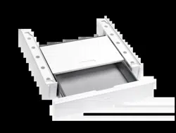
09351780 Stacking kit WT V 511 (Fig. 1)
09351790 Stacking kit WTV 512 (Fig. 1)
Installation Instructions
x
Warning!
Heat-pump dryers should be transported as shown in Fig. 3. If the dryer has not been transported in this fashion, it
should remain idle for at least one hour before reconnecting to the power supply. Otherwise, the heat pump could become
damaged.
Note
The cardboard insert in the drawer acts as a shipping strut and an installation guide. Remove this cardboard insert
immediately after installation!
A Unscrew and adjust the dryer feet (Fig. 4).
A Rotate the frame with the drawer installed (Fig. 5).
A Attach the seals (Fig. 6).
A Rotate the frame and center it on top of the washer (Fig. 7).
A Align the front panel flush with the washer fascia panel (Fig. 8).
A Carefully secure the frame to the washer lid using a manual screwdriver. Do not overtighten the screws (Fig. 9, Pos. A).
A Remove the cardboard insert from the drawer (Fig. 9, Pos. B).
A Press in on the drawer to release it, and pull it out (Fig. 10).
A Pressing in on the snap locks on both sides of the drawer, lift the drawer up to remove (Fig. 11).
A Install the dryer on the frame and push the rear dryer feet into their adapters (Fig. 12, Pos. A and Fig. 13, Pos. A).
A Then place the front dryer feet in their adapters (Fig. 12, Pos. B and Fig. 13, Pos. B).
A Secure the panels (Fig. 14, Pos. 1, Pos. 2).
A Insert the drawer:
A Place the drawer on the guide rails and close it. The drawer will click into position.
A To make sure that the drawer has snapped properly into the guide rails, open and close it again.
x
Note
After installation it may be necessary to re-align the front panel:
• Take off the cover caps (Fig. 15, Pos. A).
• To adjust the panel vertically, turn the dials on the left and right sides (Fig. 15, Pos. B).
• To adjust the panel horizontally, turn the screw on the right side (Fig. 16).
Produktgruppe 19 Umbau- und Montageanweisung
24 von 26 M.-Nr. 09352090
10.02.2014 Diese Unterlagen dürfen ohne unsere Genehmigung weder vervielfältigt noch Dritten zugänglich gemacht werden. Eigentumsrechte vorbehalten.
Loading ...
Loading ...