perator s
P R 0 F E S S I 0 N A
LAWN TRACTOR
26 HP, 46" Tractor
PYT9000
Model No. 247.288881
• EspaSol, p. 63
This product has a low emission engine which operates differently
from previously built engines. Before you start the engine, read and
understand this Operator's Manual.
iMPORTANT:
Read and follow all Safety
Rules and instructions before
operating this equipment.
For answers to your questions about
this product, Call:
1=800=659=5917
Craftsman Tractor Help Line
5am = 5 pro, Mort =Sat
Sears Brands Management Corp., Hoffman Estates, IL 60179 U.S.A.
Visit our website: www.craftsman.com FormNo.769-06504A
(January1,2011)
Warranty Statement .......................................................... 2
Safety instructions ............................................................ 3
Safety Labels .................................................................... 9
Assembly ......................................................................... 10
Know your Lawn Mower .................................................. 13
Operation ........................................................................ 16
CRAFTSMAN PROFESSIONAL FULL WARRANTY
FORTWOYEARSfromthe dateof purchase,all non-expendablepartsof this ridingequipmentarewarrantedagainstanydefectsinmaterialor
workmanship.A defectivenon-expendablepartwill receivefreein-homerepairor replacementif repairis impossible.
FORFIVEYEARSfromthe dateof purchase,theframeandfrontaxleof this ridingequipmentarewarrantedagainstanydefectsin materialor
workmanship.A defectiveframe or front axle will receivefree in-homerepairor replacementif repairis impossible.
All of the abovewarrantycoverageappliesfor onlyoneyearfromthe dateof purchaseif this riding equipmentis everusedwhileproviding
commercialservicesor if rentedto anotherperson.
FOR90 DAYSfromthedate of purchase,the battery(anexpendablepart) of this ridingequipmentis warrantedagainstany defectsin materialor
workmanship(ourtestingprovesthatit will not holda charge).A defectivebatterywill receivefreein-homereplacement.
ADDiTiONALLiFETiMELiMiTEDWARRANTYon CASTiRON FRONTAXLE (if equipped)
FORASLONGAS IT IS USEDby the originalownerafter the fifth yearfromthedate of purchase,
the cast ironfrontaxle (if equipped)of thisriding equipmentiswarrantedagainstanydefectsinmaterial
or workmanship.Withproofof purchase,a defectivecastfrontaxlewill receivefree in-homereplacement.
WARRANTYSERVICE
Forwarrantycoveragedetailsto obtainfree repairor replacement,call 1-800-659-5917or visit theweb site:www. craftsman.corn
Inall casesabove,ifpart repairor replacementisimpossible,the ridingequipmentwill bereplacedfreeof chargewiththe sameor an equivalent
model.
ThiswarrantycoversONLYdefectsin materialand workmanship.WarrantycoveragedoesNOT include:
• Expendableparts(exceptfor battery)that can wearoutfrom normalusewithinthe warrantyperiod,includingbutnot limitedto blades,
sparkplugs,air cleaners,belts,andoil filters.
• Standardmaintenanceservicing,oil changes,ortune-ups.
• Tire replacementor repaircausedbypuncturesfromoutsideobjects,suchas nails,thorns,stumps,or glass.
Tire or wheel replacementor repairresultingfrom normalwear,accident,or improperoperationor maintenance.
Repairsnecessarybecauseof operatorabuse,includingbut not limitedto damagecausedby towingobjectsbeyondthe capabilityof
the ridingequipment,impactingobjectsthatbend the frame,axle assemblyor crankshaft,orover-speedingthe engine.
• Repairsnecessarybecauseof operatornegligence,includingbut notlimitedto,electricaland mechanicaldamagecausedby improper
storage,failureto use thepropergradeand amountof engineoil, failureto keepthe deckclearof flammabledebris,or failureto
maintainthe ridingequipmentaccordingto the instructionscontainedinthe operator'smanual.
• Engine(fuel system)cleaningor repairscausedby fueldeterminedto be contaminatedor oxidized(stale). Ingeneral,fuelshouldbe
usedwithin30daysof its purchasedate.
• Normaldeteriorationandwearof theexteriorfinishes,or productlabelreplacement.
Thiswarrantygives youspecificlegalrights,and you mayalso haveother rightswhich varyfrom stateto state.
Sears Brands ManagementCot
EngineOil: SAE30
Fuel: UnleadedGasoline
SparkPlug: Champion®RC12YC
Engine: Briggs& StrattonProfessionalSeries
_oration,Hoffman Estates,IL 60179
Model Number
Serial Number
Dateof Purchase
Recordthe modelnumber,serialnumber,
anddateof purchaseabove.
© SearsBrands,LLC 2
Thissymbolpointsout importantsafetyinstructionswhich,if not
followed,couldendangerthepersonalsafetyand/orpropertyof
yourselfand others. Readand followall instructionsin this manual
beforeattemptingto operatethis machine.Failureto complywith
theseinstructionsmayresultin personalinjury.Whenyou seethis
symbol,HEEDITSWARNING!
CALIFORNIA PROPOSITION 65
EngineExhaust,someof itsconstituents,andcertainvehicle
componentscontainoremit chemicalsknownto Stateof California
to cause cancerand birthdefects or other reproductiveharm.
Batteryposts,terminals,and relatedaccessoriescontainleadand
leadcompounds,chemicalsknownto the Stateof Californiato
causecancerand reproductiveharm.Washhandsafterhandling.
Thismachinewasbuiltto be operatedaccordingto the safeopera-
tion practicesin this manual.As withanytypeof powerequipment,
carelessnessorerroron the partof the operatorcan resultin serious
injury.Thismachineis capableof amputatingfingers,hands,toes
andfeet and throwingdebris.Failureto observethe followingsafety
instructionscouldresultin seriousinjuryor death.
Your Responsibility--Restrictthe use of thispowermachineto
personswho read,understandand follow thewarningsand instruc-
tionsin this manualandon the machine.
SAVE THESE INSTRUCTIONS!
GENERAL OPERATION
• Read,understand,andfollowall instructionson the machineand
in themanual(s)beforeattemptingto assembleand operate.
Keepthis manualin a safe placefor futureand regularreference
andfor orderingreplacementparts.
• Befamiliarwith all controlsandtheir properoperation.Knowhow
to stop the machineanddisengagethemquickly.
• Neverallowchildrenunder 14 yearsold to operatethis machine.
Children14 yearsold and over shouldreadandunderstandthe
operationinstructionsand safety rulesinthis manualandshould
betrainedandsupervisedbya parent.
• Neverallowadultsto operatethis machinewithoutproper
instruction.
• Tohelpavoidbladecontactor a thrownobjectinjury,keep
bystanders,helpers,childrenand pets at least75 feet fromthe
machinewhile it is in operation.Stopmachineif anyoneenters
the area.
• Thoroughlyinspectthe areawherethe equipmentis to be used.
Removeall stones,sticks,wire, bones,toys,and otherforeign
objectswhich couldbe pickedup and thrownby the blade(s).
Thrownobjectscan causeseriouspersonalinjury.
• Planyour mowingpatternto avoiddischargeof materialtoward
roads,sidewalks,bystandersandthe like.Also, avoiddischarg-
ingmaterialagainstawall orobstructionwhichmaycause
dischargedmaterialto ricochetback towardthe operator.
• Alwayswear safetyglassesor safetygogglesduringoperation
andwhile performingan adjustmentor repairto protectyoureyes.
Thrownobjectswhichricochetcancauseseriousinjuryto the
eyes.
• Wearsturdy,rough-soledworkshoesandclose-fittingslacksand
shirts.Loosefittingclothesandjewelry canbe caughtin movable
parts.Neveroperatethis machinein bare feet or sandals.
• Beawareof the mowerandattachmentdischargedirectionand
do not pointit at anyone.Donot operatethe mowerwithoutthe
dischargecoverorentiregrasscatcherin its properplace.
Donot put handsor feetnear rotatingpartsor underthe cutting
deck. Contactwith the blade(s)can amputatehandsand feet.
A missingor damageddischargecovercan causeblade contact
or thrownobjectinjuries.
• Stoptheblade(s)whencrossinggraveldrives,walks,or roads
andwhile notcuttinggrass.
• Watchfor trafficwhenoperatingnear or crossingroadways.This
machineis not intendedfor useonany public roadway.
• Donot operatethe machinewhile underthe influenceof alcohol
or drugs.
• Mowonly in daylightor good artificiallight.
Nevercarrypassengers.
• Disengageblade(s)beforeshiftinginto reverse.Backup slowly.
Alwayslookdownandbehindbeforeandwhile backingto avoida
back-overaccident.
3
• Slowdownbeforeturning.Operatethe machinesmoothly.Avoid
erraticoperationand excessivespeed.
Disengageblade(s),setparkingbrake,stopengineand wait until
the blade(s)cometo a completestopbeforeremovinggrass
catcher,emptyinggrass,uncloggingchute,removinganygrass or
debris,or makinganyadjustments.
Neverleavea runningmachineunattended.Alwaysturnoff
blade(s),setparkingbrake,stopengineand removekey before
dismounting.
Useextracare whenloadingorunloadingthe machineintoa
trailerortruck.Thismachineshouldnot bedrivenup or down
ramp(s),becausethe machinecouldtip over,causingserious
personalinjury.The machinemustbe pushedmanuallyon
ramp(s)to loador unloadproperly.
Mufflerand engine becomehotand can causea burn.Do not
touch.
Checkoverheadclearancescarefullybeforedrivingunderlow
hangingtree branches,wires,door openingsetc.,wherethe
operatormay be struckor pulledfrom the machine,whichcould
resultinseriousinjury.
Disengageallattachmentclutchesand depressthe brakepedal
completelybeforeattemptingto start engine.
Yourmachineisdesignedto cut normalresidentialgrassof a
heightnomorethan 10".Do not attemptto mowthroughunusually
tall,dry grass (e.g.,pasture)orpiles of dry leaves.Drygrassor
leavesmaycontactthe engineexhaustand/or build uponthe
mowerdeckpresentinga potentialfire hazard.
Useonlyaccessoriesand attachmentsapprovedfor this machine
by the machinemanufacturer.Read,understandandfollowall
instructionsprovidedwith the approvedaccessoryor attachment.
Fora list of approvedaccessoriesandattachments,call 1-800-
659-5917.
Dataindicatesthatoperators,age 60 years and above,are
involvedin a largepercentageof riding mower-relatedinjuries.
Theseoperatorsshouldevaluatetheirability to operatethe riding
mowersafelyenoughto protectthemselvesandothersfrom
seriousinjury.
If situationsoccurwhicharenot coveredin this manual,usecare
andgoodjudgment.Contact1-800-659-5917for informationand
assistance.
SLOPE OPERATION
Slopesarea majorfactorrelatedto lossof controlandtip-over
accidentswhichcan result in severeinjuryor death.All slopes require
extracaution.Ifyoucannotback up the slopeor if youfeel uneasyon
it, do not mowit.
Foryoursafety,use the SlopeGuideincludedas partof this manual
to measureslopesbeforeoperatingthis machineona slopedor hilly
area. If the slopeis greaterthan15degreesas shownonthe Slope
Guide,do notoperatethis machineonthat area or seriousinjurycould
result.
Do:
o
Mowupand down slopes,not across.Exerciseextremecaution
whenchangingdirectionon slopes.
• Watchfor holes,ruts,bumps,rocks,orother hiddenobjects.
Uneventerraincouldoverturnthe machine.Tallgrasscan hide
obstacles.
Useslowspeed.Choosea lowenoughspeedsettingso that
you will nothaveto stopor shiftwhileon the slope.Tiresmay
lose tractionon slopeseventhoughthe brakesare functioning
properly.Alwayskeepmachinein gearwhen goingdownslopes
to take advantageof enginebrakingaction.
• Followthe manufacturer'srecommendationsfor wheelweights
or counterweightsto improvestability.Forrecommendations,call
1-800-659-5917.
• Useextracarewithgrasscatchersor otherattachments.These
can changethe stabilityof the machine.
Keepallmovementonthe slopesslowand gradual.Do not make
suddenchangesinspeedor direction.Rapidengagementor
brakingcouldcausethe frontof the machineto lift andrapidlyflip
overbackwardswhichcouldcauseseriousinjury.
• Avoidstartingor stoppingona slope.Iftireslosetraction,disen-
gagethe blade(s)and proceedslowlystraightdownthe slope.
DoNot:
• Donot turnon slopesunlessnecessary;then, turnslowlyand
graduallydownhill,if possible.
• Donot mowneardrop-offs,ditchesor embankments.The mower
could suddenlyturnover if a wheelis overthe edgeof a cliff,
ditch,or if an edgecavesin.
• Donot try to stabilizethe machineby puttingyourfooton the
ground.
• Donot usea grasscatcheron steepslopes.
• Donot mowon wetgrass.Reducedtractioncouldcausesliding.
• Donot attemptto coastdownhill.Over-speedingmaycausethe
operatorto lose controlof the machineresultingin seriousinjury
or death.
• Donot towheavypull behindattachments(e.g. loadeddumpcart,
lawn roller,etc.)on slopesgreaterthan5 degrees.Whengoing
down hill,the extraweighttendsto pushthe tractorandmay
causeyou to loosecontrol(e.g.tractormay speedup, brakingand
steeringabilityare reduced,attachmentmayjack-knifeandcause
tractorto overturn).
4
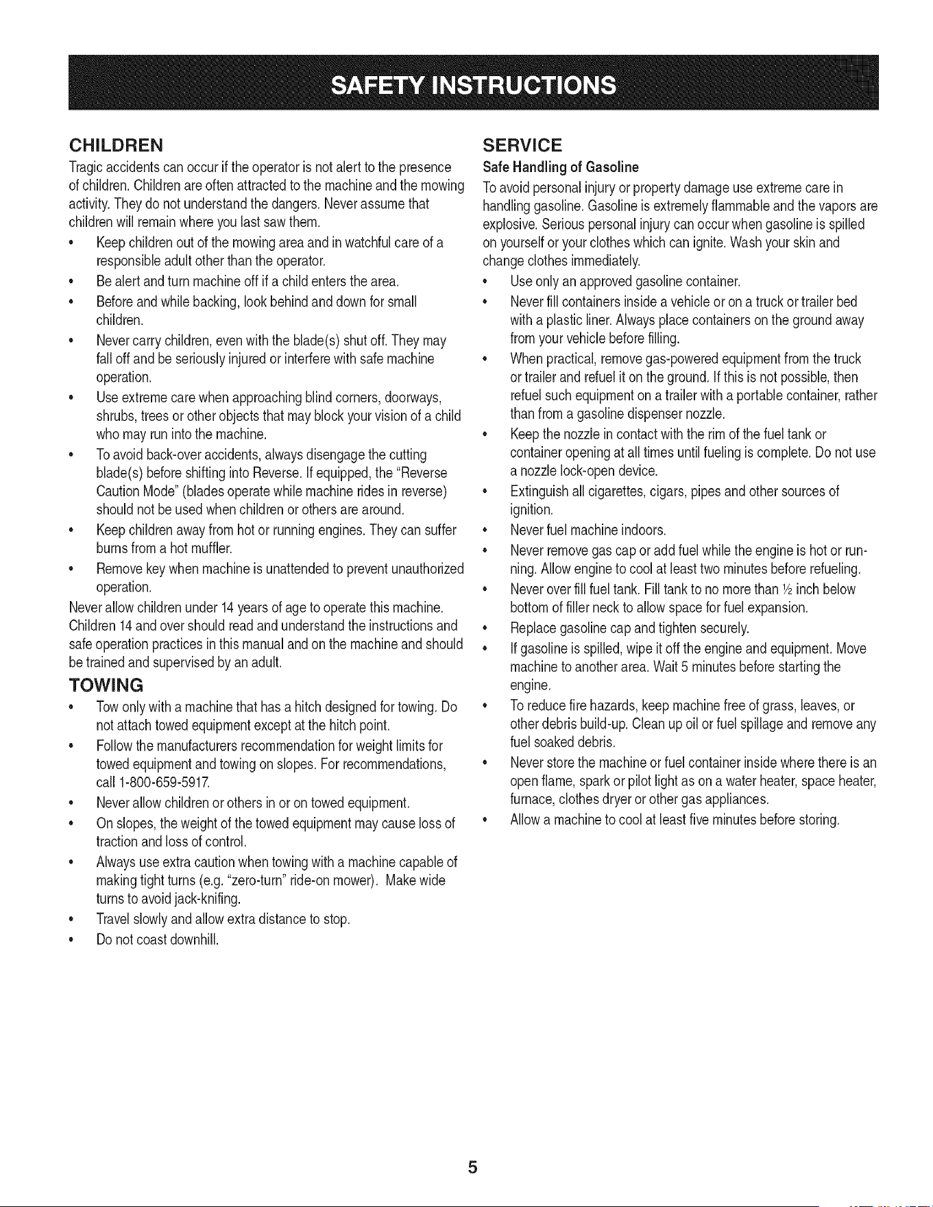
CHILDREN
Tragicaccidentscanoccurifthe operatoris notalert to the presence
of children.Childrenare often attractedto the machineand the mowing
activity.Theydo notunderstandthe dangers.Neverassumethat
childrenwill remainwhereyou lastsawthem.
• Keepchildrenout of the mowingareaand inwatchfulcare of a
responsibleadultotherthanthe operator.
• Bealert andturnmachineoff ifa childentersthe area.
• Beforeandwhilebacking,lookbehindanddownfor small
children.
Nevercarrychildren,evenwiththe blade(s)shutoff.Theymay
fall off and be seriouslyinjuredorinterferewith safe machine
operation.
• Useextremecarewhenapproachingblindcorners,doorways,
shrubs,trees or otherobjectsthatmay block yourvisionof a child
whomayrunintothe machine.
Toavoidback-overaccidents,alwaysdisengagethe cutting
blade(s)beforeshiftingintoReverse.If equipped,the "Reverse
CautionMode"(bladesoperatewhilemachineridesinreverse)
shouldnotbe usedwhenchildrenor othersare around.
Keepchildrenaway from hotor runningengines.They cansuffer
burnsfroma hotmuffler.
• Removekeywhenmachineisunattendedto preventunauthorized
operation.
Neverallowchildrenunder 14 yearsof ageto operatethis machine.
Children14 and overshouldreadandunderstandthe instructionsand
safeoperationpracticesinthismanualand on the machineandshould
betrainedandsupervisedbyan adult.
TOWING
Towonlywitha machinethathasa hitch designedfor towing.Do
not attachtowedequipmentexceptat the hitchpoint.
Followthe manufacturersrecommendationforweightlimitsfor
towedequipmentandtowingon slopes.For recommendations,
call 1-800-659-5917.
Neverallowchildrenor othersinor on towedequipment.
Onslopes,theweightof thetowed equipmentmaycause lossof
tractionand loss of control.
Alwaysuseextracautionwhentowingwith a machinecapableof
makingtightturns (e.g."zero-turn"ride-onmower). Makewide
turnsto avoidjack-knifing.
Travelslowlyandallowextradistanceto stop.
Do notcoastdownhill.
SERVICE
SafeHandlingof Gasoline
Toavoidpersonalinjuryorpropertydamageuse extremecarein
handlinggasoline.Gasolineisextremelyflammableandthe vaporsare
explosive.Seriouspersonalinjurycanoccur whengasolineis spilled
on yourselfor your clotheswhich can ignite.Washyourskin and
changeclothesimmediately.
• Useonly an approvedgasolinecontainer.
Neverfill containersinsidea vehicleoron a truckortrailer bed
witha plasticliner.Alwaysplacecontainerson the groundaway
fromyourvehiclebeforefilling.
Whenpractical,removegas-poweredequipmentfromthe truck
or trailerandrefueliton theground.Ifthis isnot possible,then
refuelsuch equipmenton a trailerwitha portablecontainer,rather
than froma gasolinedispensernozzle.
Keepthe nozzleincontactwith the rim of the fueltankor
containeropeningat all timesuntilfuelingiscomplete.Donot use
a nozzlelock-opendevice.
Extinguishall cigarettes,cigars,pipesandothersourcesof
ignition.
• Neverfuel machineindoors.
Neverremovegascap or addfuelwhilethe engineis hotor run-
ning.Allowengineto coolat least two minutesbeforerefueling.
Neveroverfill fuel tank. Filltankto no morethan 1/2inchbelow
bottomof filler neckto allowspaceforfuel expansion.
• Replacegasolinecap andtightensecurely.
• Ifgasolineis spilled,wipeitoff the engineandequipment.Move
machineto anotherarea.Wait5 minutesbeforestartingthe
engine.
• To reducefire hazards,keepmachinefree of grass,leaves,or
otherdebrisbuild-up.Cleanup oilor fuel spillageandremoveany
fuel soakeddebris.
• Neverstorethe machineor fuelcontainerinsidewherethere isan
openflame,sparkor pilotlight as ona waterheater,spaceheater,
furnace,clothesdryeror othergasappliances.
Allowa machineto coolat leastfiveminutesbeforestoring.
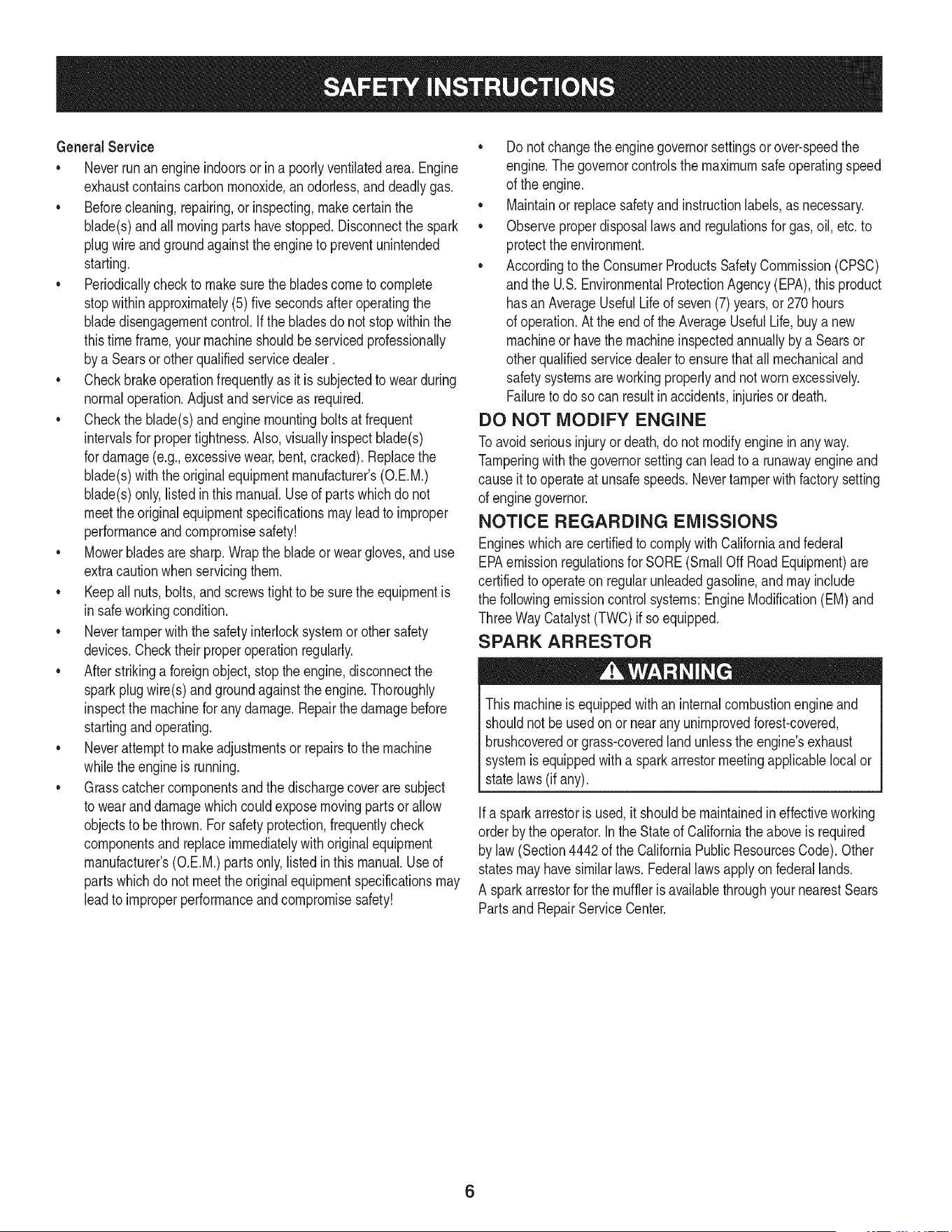
GeneralService
• Neverrunanengineindoorsorina poorlyventilatedarea.Engine
exhaustcontainscarbonmonoxide,anodorless,anddeadlygas.
• Beforecleaning,repairing,orinspecting,makecertainthe
blade(s)andallmovingpartshavestopped.Disconnectthespark
plugwireandgroundagainsttheenginetopreventunintended
starting.
• Periodicallychecktomakesurethebladescometocomplete
stopwithinapproximately(5)fivesecondsafteroperatingthe
bladedisengagementcontrol.Ifthebladesdonotstopwithinthe
thistimeframe,yourmachineshouldbeservicedprofessionally
byaSearsorotherqualifiedservicedealer.
• Checkbrakeoperationfrequentlyasitissubjectedtowearduring
normaloperation.Adjustandserviceasrequired.
• Checktheblade(s)andenginemountingboltsatfrequent
intervalsforpropertightness.Also,visuallyinspectblade(s)
fordamage(e.g.,excessivewear,bent,cracked).Replacethe
blade(s)withtheoriginalequipmentmanufacturer's(O.E.M.)
blade(s)only,listedinthismanual.Useofpartswhichdonot
meettheoriginalequipmentspecificationsmayleadtoimproper
performanceandcompromisesafety!
• Mowerbladesaresharp.Wrapthebladeorweargloves,anduse
extracautionwhenservicingthem.
• Keepallnuts,bolts,andscrewstighttobesuretheequipmentis
insafeworkingcondition.
• Nevertamperwiththe safetyinterlocksystemor othersafety
devices.Checktheir properoperationregularly.
• Afterstrikinga foreignobject,stopthe engine,disconnectthe
sparkplugwire(s)andgroundagainstthe engine.Thoroughly
inspectthe machinefor anydamage.Repairthe damagebefore
startingandoperating.
• Neverattemptto makeadjustmentsor repairsto the machine
whilethe engineis running.
• Grasscatchercomponentsandthe dischargecoverare subject
to wearanddamagewhichcouldexposemovingpartsor allow
objectsto be thrown.Forsafetyprotection,frequentlycheck
componentsand replaceimmediatelywithoriginalequipment
manufacturer's(O.E.M.)partsonly,listedinthis manual.Use of
partswhichdo not meetthe originalequipmentspecificationsmay
leadto improperperformanceandcompromisesafety!
• Donot changethe enginegovernorsettingsorover-speedthe
engine.The governorcontrolsthe maximumsafe operatingspeed
of the engine.
Maintainor replacesafetyand instructionlabels,as necessary.
• Observeproperdisposallawsand regulationsfor gas,oil, etc.to
protecttheenvironment.
• Accordingto the ConsumerProductsSafetyCommission(CPSC)
andthe U.S.EnvironmentalProtectionAgency(EPA),this product
has an AverageUsefulLifeof seven(7)years,or 270hours
of operation.At the end of the AverageUsefulLife,buy anew
machineor havethe machineinspectedannuallybya Searsor
otherqualifiedservicedealerto ensurethat all mechanicaland
safetysystemsareworkingproperlyandnot wornexcessively.
Failureto doso can resultinaccidents,injuriesor death.
DO NOT MODIFY ENGINE
Toavoid seriousinjuryor death,do notmodifyenginein anyway.
Tamperingwiththe governorsettingcanleadto a runawayengineand
causeit to operateat unsafespeeds.Nevertamper with factorysetting
of enginegovernor.
NOTICE REGARDING EMISSIONS
Engineswhicharecertifiedto complywithCaliforniaandfederal
EPAemissionregulationsfor SORE(SmallOffRoadEquipment)are
certifiedto operateon regularunleadedgasoline,andmayinclude
the followingemissioncontrolsystems:EngineModification(EM)and
ThreeWayCatalyst(TWO)if so equipped.
SPARK ARRESTOR
Thismachineis equippedwith an internalcombustionengineand
shouldnotbe usedon or near anyunimprovedforest-covered,
brushcoveredorgrass-coveredlandunlessthe engine'sexhaust
systemisequippedwitha sparkarrestormeetingapplicablelocalor
statelaws(if any).
Ifa sparkarrestoris used,it shouldbe maintainedin effectiveworking
orderby the operator.Inthe Stateof Californiatheaboveis required
by law (Section4442of the CaliforniaPublicResourcesCode). Other
statesmayhavesimilarlaws.Federallaws applyonfederallands.
A sparkarrestorfor the muffleris availablethroughyournearestSears
PartsandRepairServiceCenter.
6
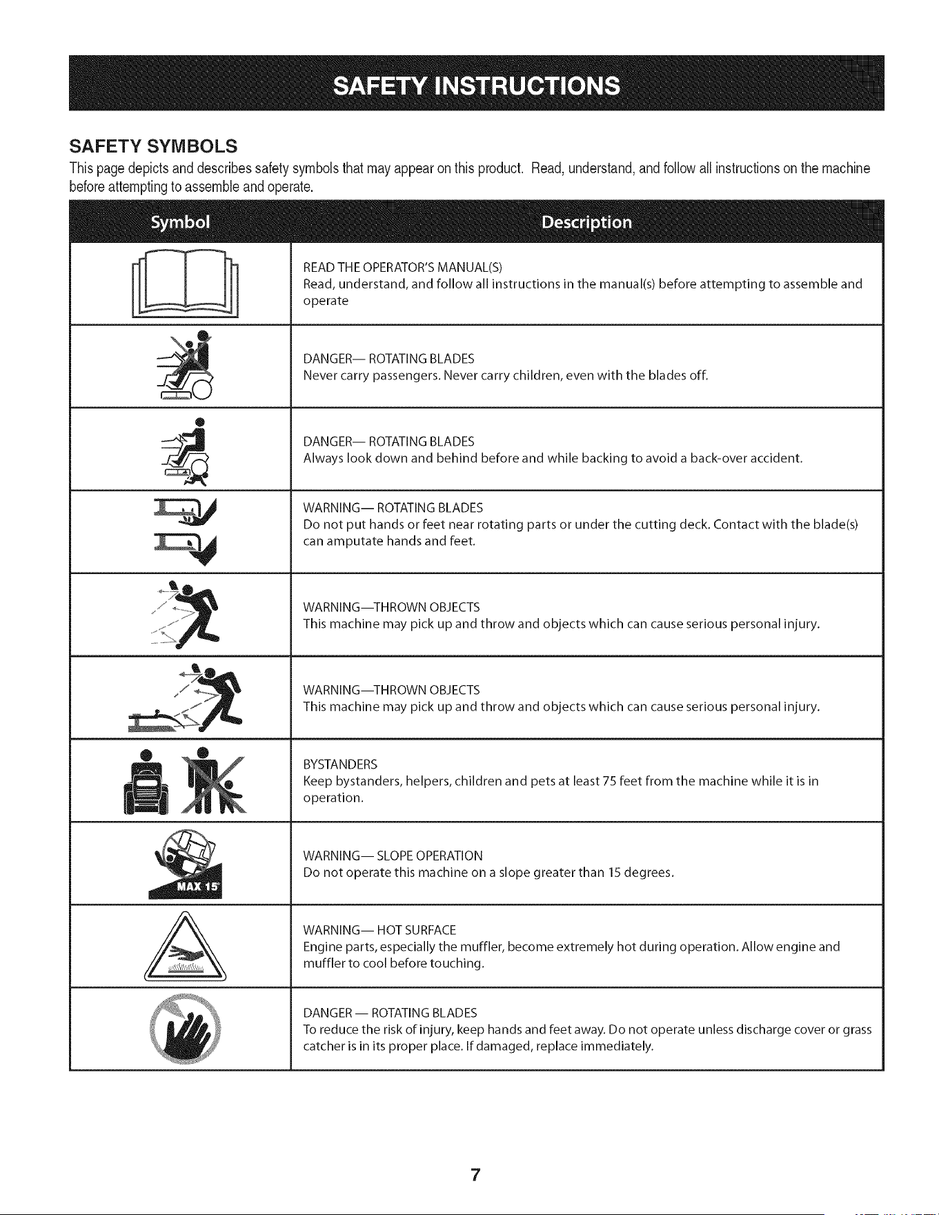
SAFETY SYMBOLS
Thispagedepictsanddescribessafety symbolsthat may appearon this product. Read,understand,andfollowallinstructionson the machine
beforeattemptingto assembleand operate.
O
A
READ THE OPERATOR'S MANUAL(S)
Read, understand, and follow all instructions in the manual(s) before attempting to assemble and
operate
DANGER-- ROTATING BLADES
Never carry passengers. Never carry children, even with the blades off.
DANGER-- ROTATING BLADES
Always look down and behind before and while backing to avoid a back-over accident.
WARNING-- ROTATING BLADES
Do not put hands or feet near rotating parts or under the cutting deck. Contact with the blade(s)
can amputate hands and feet.
WARNING--THROWN OBJECTS
This machine may pick up and throw and objects which can cause serious personal injury.
WARNING--THROWN OBJECTS
This machine may pick up and throw and objects which can cause serious personal injury.
BYSTANDERS
Keep bystanders, helpers, children and pets at least 75 feet from the machine while it is in
operation.
WARNING-- SLOPE OPERATION
Do not operate this machine on a slope greater than 15 degrees.
WARNING-- HOT SURFACE
Engine parts, especially the muffler, become extremely hot during operation. Allow engine and
muffler to cool before touching.
DANGER- ROTATING BLADES
To reduce the risk of injury, keep hands and feet away. Do not operate unless discharge cover or grass
catcher is in its proper place. If damaged, replace immediately.
7

Sight and hold this levelwith a vertical tree...
or a corner of a building...
15°
Use this page as a guide to determine slopes where you may not operate safely.
Donot operateyourlawnmoweron such slopes.Do notmowon inclineswitha slope inexcessof 15degrees(a rise of approximately2ol/2 feet every 10feet). A riding
mowercouldoverturnand causeseriousinjury.Operateriding mowersupanddownslopes,neveracrossthe faceof slopes.
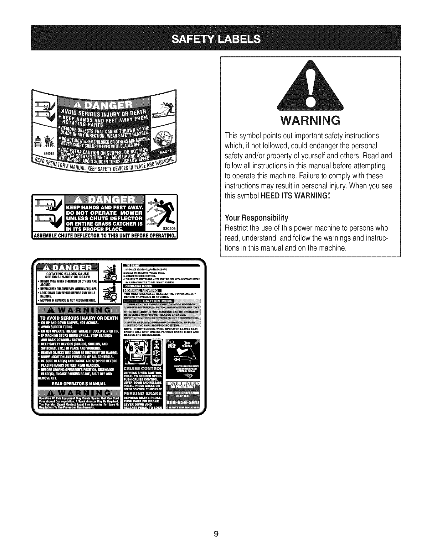
WARNING
This symbol points out important safety instructions
which, if not followed, could endanger the personal
safety and/or property of yourself and others. Readand
follow all instructions in this manual before attempting
to operatethis machine. Failureto comply with these
instructions may result in personal injury. When you see
this symbol HEED ITS WARNING!
Your Responsibility
Restrictthe use of this power machineto persons who
read, understand, and follow the warnings and instruc-
tions in this manualand on the machine.
ROTATING BLADES CAUSE
SERIOUS INJURY OR DEATH
• DONOTMOWWHENCHILDRENOROTHERSARE
AROUND
• NEVERCARRYCHILDRENEVENWITHBLaDE(S)OFF.
• LOOKDOWNANDNEMDONEFORSANDWHILE
BACKING.
• MOWINGINREVERSEISNOTRECOMMENDED.
NOTE: IN BOTH MODES, WHEN OPERATOR LEAVES SEAT,
ENGINE WILL STOP UNLESS PARKING BRAKE IS SET AND
BLAINS AR_ DISEHGAGE_
9
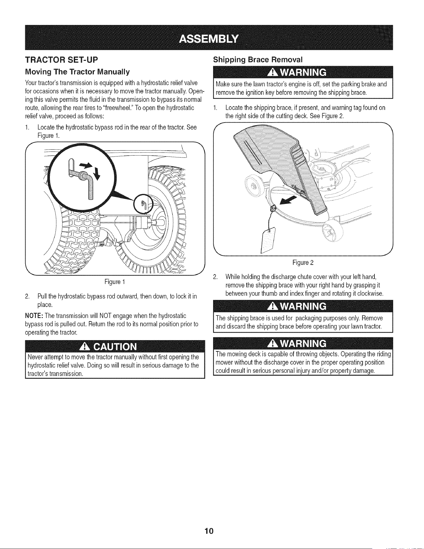
TRACTOR SET-UP
Moving The Tractor Manually
Yourtractor'stransmissionis equippedwith a hydrostaticreliefvalve
for occasionswhenit is necessaryto movethe tractormanually.Open-
ingthisvalvepermitsthe fluidin the transmissionto bypassits normal
route,allowingthe reartiresto "freewheel."Toopenthe hydrostatic
reliefvalve,proceedas follows:
1. Locatethe hydrostaticbypassrodinthe rearof thetractor.See
Figure1.
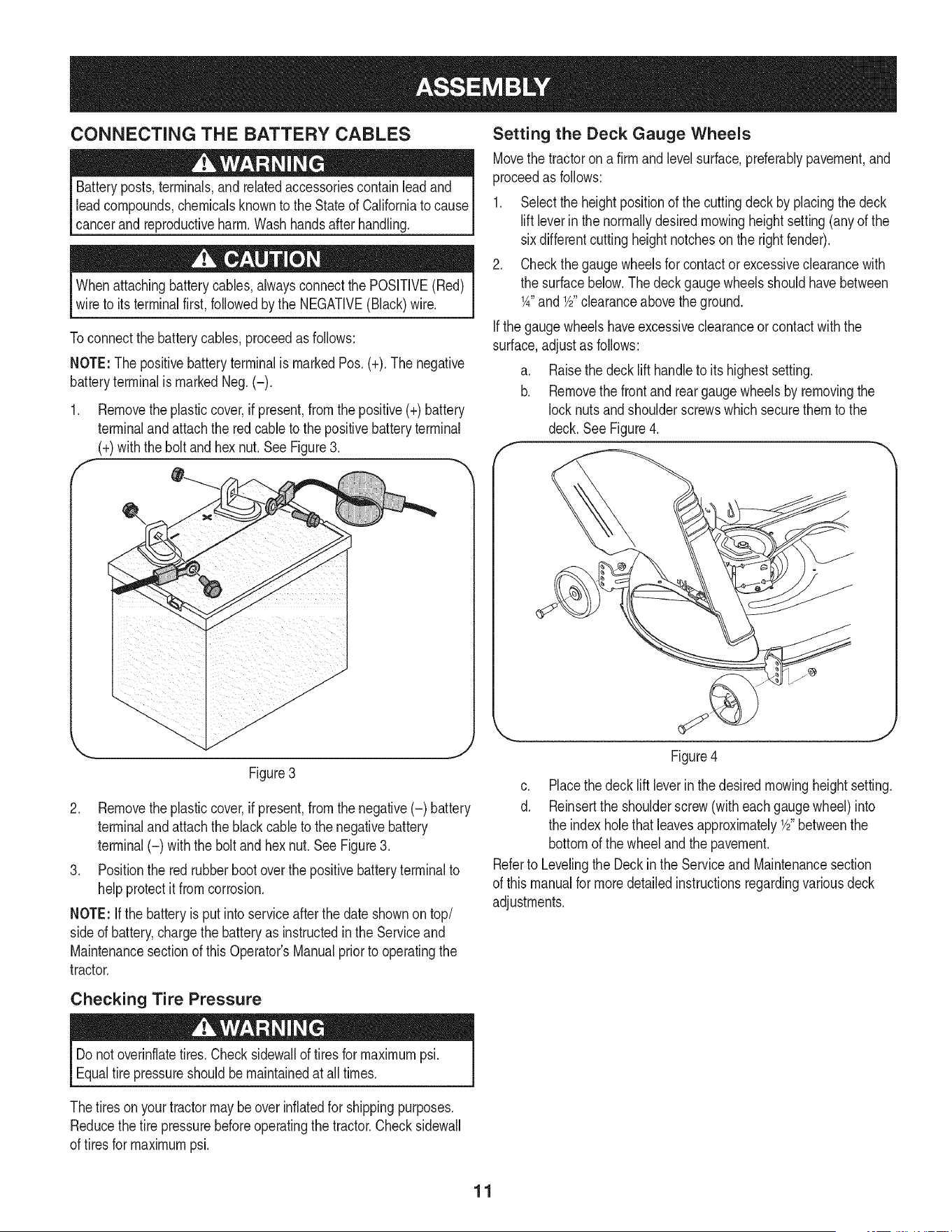
Shipping Brace Removal
Makesurethe lawntractor'sengineisoff, set the parkingbrakeand
removethe ignitionkeybeforeremovingthe shippingbrace.
1. Locatethe shippingbrace, if present,and warningtag foundon
the rightsideof the cuttingdeck.SeeFigure2.
Figure1
2. Pull the hydrostaticbypassrod outward,then down,to lockit in
place.
NOTE:The transmissionwill NOTengagewhenthe hydrostatic
bypassrodis pulledout. Returnthe rodto itsnormalpositionprior to
operatingthe tractor.
.
Figure2
Whileholdingthe dischargechute coverwith yourleft hand,
removethe shippingbracewithyourright handby graspingit
betweenyourthumband indexfingerand rotatingit clockwise.
The shippingbraceis usedfor packagingpurposesonly.Remove
anddiscardthe shippingbracebeforeoperatingyour lawntractor.
Neverattemptto movethetractormanuallywithoutfirst openingthe
hydrostaticreliefvalve.Doingsowill resultin seriousdamageto the
tractor'stransmission.
The mowingdeck is capableof throwingobjects. Operatingthe riding
mowerwithoutthe dischargecoverin theproperoperatingposition
could resultin seriouspersonalinjuryand/orpropertydamage.
10
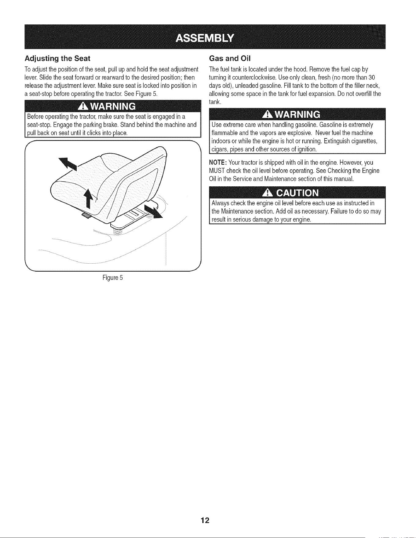
CONNECTING THE BATTERY CABLES
Batteryposts,terminals,andrelatedaccessoriescontainleadand
leadcompounds,chemicalsknownto the Stateof Californiato cause
cancerand reproductiveharm.Washhandsafterhandling.
Whenattachingbatterycables,alwaysconnectthe POSiTiVE(Red)
wire to its terminalfirst,followedbythe NEGATIVE(Black)wire.
Toconnectthe batterycables,proceedas follows:
NOTE:The positivebatteryterminalis markedPos.(+). The negative
batteryterminalis markedNeg.(-).
1. Removetheplasticcover,if present,fromthe positive(+)battery
terminalandattachthe redcable to the positivebatteryterminal
(+)withthe bolt andhexnut.See Figure3.
f -,
Figure3
2. Removetheplasticcover,if present,fromthe negative(-) battery
terminalandattachthe blackcableto the negativebattery
terminal(-) withthe bolt and hex nut.SeeFigure3.
3. Positionthe red rubberbootoverthe positivebatteryterminalto
helpprotectit fromcorrosion.
NOTE: If the batteryis put intoserviceafterthe dateshownontop/
sided battery,chargethe batteryas instructedinthe Serviceand
Maintenancesectionof this Operator'sManualpriorto operatingthe
tractor.
Setting the Deck Gauge Wheels
Movethe tractoron afirm and levelsurface,prderably pavement,and
proceedas follows:
1. Selectthe heightpositionof the cuttingdeck by placingthe deck
liftleverin the normallydesiredmowingheightsetting(anyof the
sixdifferentcuttingheightnotcheson the rightfender).
2. Checkthe gaugewheelsfor contactor excessiveclearancewith
the surfacebelow.The deckgaugewheelsshouldhavebetween
1A"andY2"clearanceabovethe ground.
Ifthe gaugewheelshaveexcessiveclearanceor contactwiththe
surface,adjustas follows:
a. Raisethe decklift handleto itshighestsetting.
b. Removethe frontandreargaugewheelsby removingthe
locknutsandshoulderscrewswhichsecurethemto the
deck. See Figure4.
c. Placethe decklift leverinthe desiredmowingheightsetting.
d. Reinsertthe shoulderscrew(with eachgaugewheel)into
the indexholethat leavesapproximatelyY2"betweenthe
bottomof the wheeland the pavement.
Referto Levelingthe Deckin the Serviceand Maintenancesection
of this manualfor moredetailedinstructionsregardingvariousdeck
adjustments.
Checking Tire Pressure
Do notoverinflatetires.Checksidewallof tires for maximumpsi.
Equaltire pressureshouldbemaintainedat alltimes.
Thetiresonyour tractormaybeover inflatedfor shippingpurposes.
Reducethetire pressurebeforeoperatingthe tractor.Checksidewall
of tires for maximumpsi.
11
Adjusting the Seat
Toadjustthe positionof the seat,pullup and hold the seatadjustment
lever.Slidethe seat forwardor rearwardto the desiredposition;then
releasethe adjustmentlever.Makesureseatislockedintopositionin
a seat-stopbeforeoperatingthe tractor.See Figure5.
Beforeoperatingthe tractor,make surethe seatisengagedin a
seat-stop.Engagethe parkingbrake.Standbehindthe machineand
pullbackon seatuntilitclicksintoplace.
f
,\
Figure5
Gas and Oil
The fueltank islocatedunderthe hood.Removethe fuel cap by
turningit counterclockwise.Use onlyclean,fresh(no morethan30
daysold), unleadedgasoline.Filltank to the bottomof the filler neck,
allowingsomespacein the tankfor fuel expansion.Donot overfillthe
tank.
Useextremecarewhen handlinggasoline.Gasolineis extremely
flammableand thevaporsare explosive. Neverfuelthe machine
indoorsorwhilethe engineis hotor running.Extinguishcigarettes,
cigars,pipesand othersourcesof ignition.
NOTE: Yourtractoris shippedwithoil in the engine.However,you
MUSTcheckthe oillevelbeforeoperating.See Checkingthe Engine
Oil inthe Serviceand Maintenancesectionof this manual.
Alwayscheckthe engineoil levelbeforeeach useas instructedin
the Maintenancesection.Add oil as necessary.Failureto do so may
resultinseriousdamageto your engine.
12
f
FueITankCap
Throttle/ChokeControl_
I
FuelLevelIndicator
IgnitionSwitch
Module
PTO(Blade
Knob
DrivePedal
Pedal
LiffLever
Cup Holder"
\
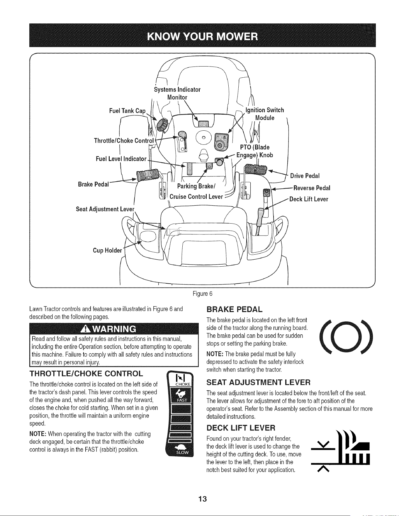
Figure6
LawnTractorcontrolsand featuresareillustratedin Figure6and
describedon thefollowingpages.
Readandfollowallsafetyrulesand instructionsinthis manual,
includingtheentireOperationsection,beforeattemptingto operate
this machine.Failureto complywithall safetyrulesand instructions
mayresultin personalinjury.
THROTTLE/CHOKE CONTROL
Thethrottle/chokecontrolis locatedon the leftsideof
the tractor'sdashpanel.Thislevercontrolsthe speed
of the engineand,whenpushedall the wayforward,
closesthechokefor cold starting.Whenset in a given
position,the throttlewillmaintaina uniformengine
speed.
NOTE:Whenoperatingthe tractorwiththe cutting
deckengaged,becertainthatthe throttle/choke
controlis alwaysinthe FAST(rabbit)position.
BRAKE PEDAL
The brakepedalis locatedon the leftfront
sideof the tractoralongthe runningboard.
The brakepedalcan beusedfor sudden
stopsor settingthe parkingbrake.
NOTE:Thebrakepedalmustbefully
depressedto activatethe safetyinterlock
switchwhenstartingthe tractor.
SEAT ADJUSTMENT LEVER
The seat adjustmentleveris locatedbelowthe front!leftof the seat.
The leverallowsfor adjustmentof the foreto aft positionof the
operator'sseat. Referto the Assemblysectionof this manualfor more
detailedinstructions.
DECK LIFT LEVER
Foundon your tractor'srightfender,
the deck lift leveris usedto changethe
heightof the cuttingdeck.To use,move
the leverto the left, thenplacein the
notchbestsuitedfor yourapplication.
A
13
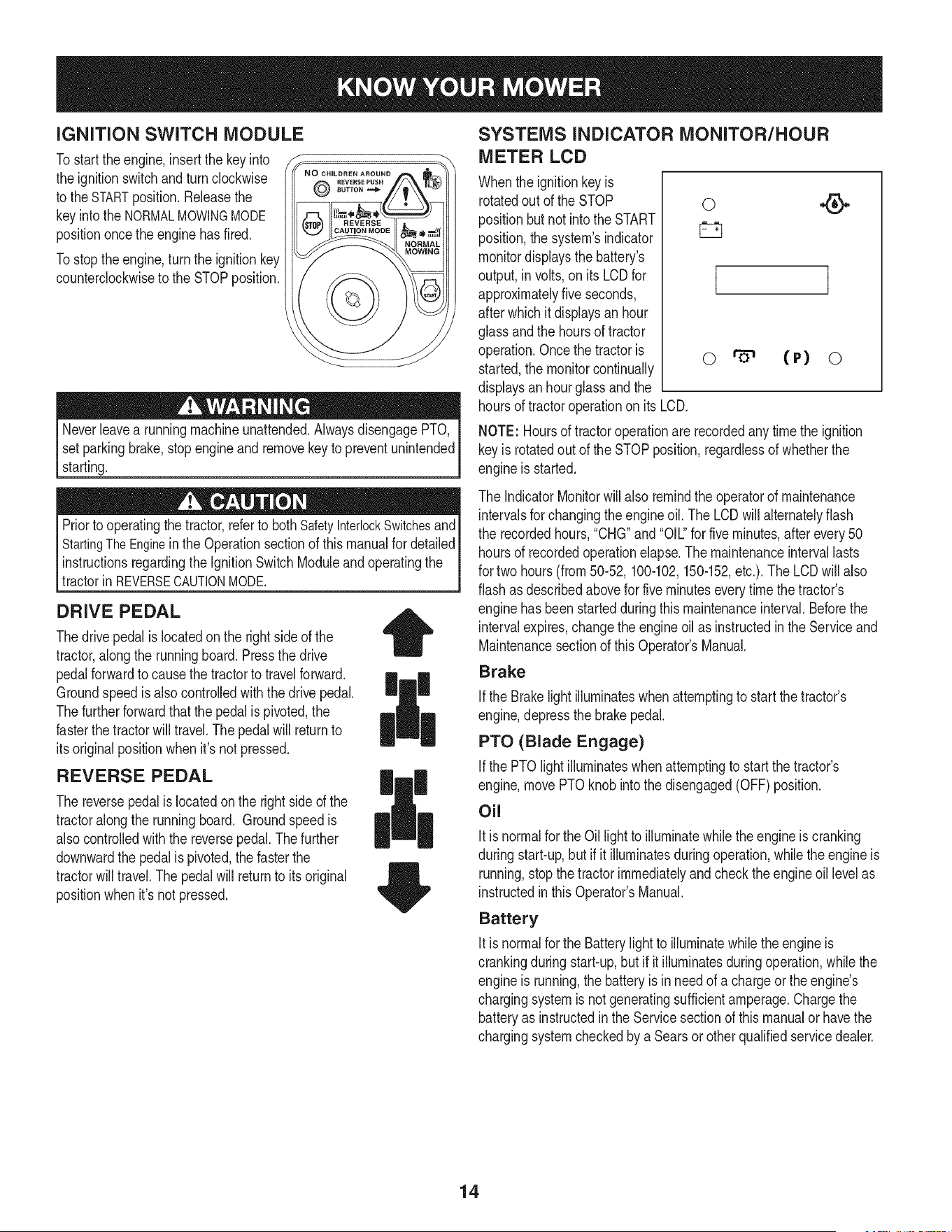
iGNiTiON SWITCH MODULE
Tostart theengine,insertthe keyinto
the ignitionswitchand turnclockwise
to the STARTposition.Releasethe
keyintothe NORMALMOWINGMODE
positiononcethe enginehas fired.
Tostoptheengine,turnthe ignitionkey
counterclockwiseto the STOPposition.
REVERS£PUSH
8UTTONm_
Neverleavea runningmachineunattended.AlwaysdisengagePTO,
setparkingbrake,stopengineand removekeyto preventunintended
starting.
Priorto operatingthe tractor,referto bothSafetyInterlockSwitchesand
StartingTheEnginein the Operationsectionof thismanualfor detailed
instructionsregardingthe IgnitionSwitchModuleand operatingthe
tractorinREVERSECAUTONMODE. j
DRIVE PEDAL
Thedrivepedal is locatedon the rightsideof the
tractor,alongthe runningboard.Pressthe drive
pedalforwardto causethe tractorto travelforward.
Groundspeedis alsocontrolledwiththe drivepedal.
Thefurtherforwardthat thepedal is pivoted,the
fasterthetractorwill travel.The pedalwill returnto
itsoriginalpositionwhen it's not pressed.
REVERSE PEDAL
The reversepedal is locatedonthe right sideof the
tractoralong the runningboard. Groundspeedis
alsocontrolledwiththe reversepedal.Thefurther
downwardthe pedalis pivoted,the fasterthe
tractorwill travel.Thepedal will returnto its original
positionwhenit's not pressed.
|
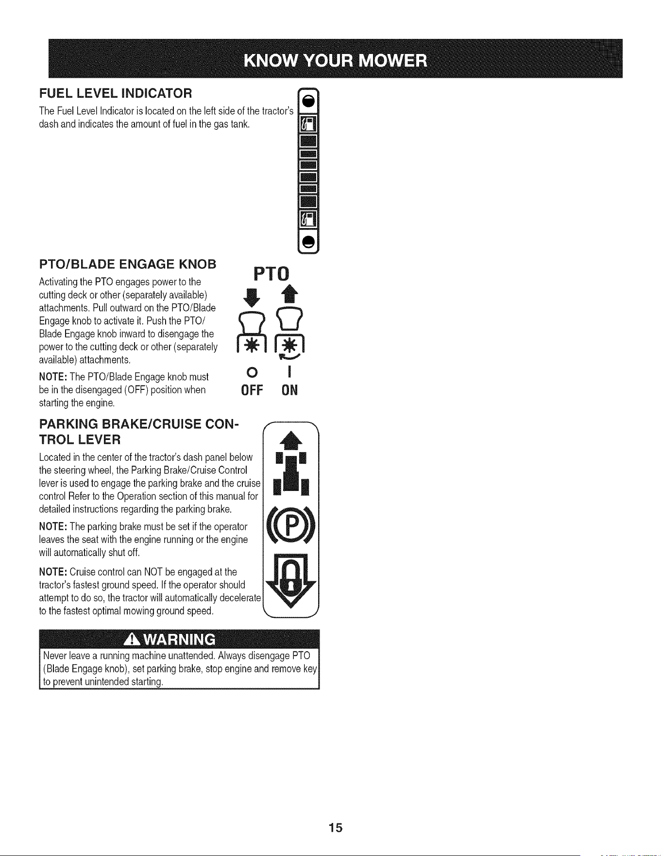
SYSTEMS INDICATOR MONITOR/HOUR
METER LCD
Whenthe ignitionkeyis
rotatedout of the STOP
positionbut not intothe START
position,thesystem'sindicator
monitordisplaysthe battery's
output,in volts,on its LCDfor
approximatelyfiveseconds,
afterwhich it displaysan hour
glassandthe hoursof tractor
operation.Oncethe tractoris
started,the monitorcontinually
displaysan hourglass and the
0
I
o (P) o
hoursof tractoroperationon its LCD.
NOTE: Hoursof tractoroperationare recordedanytime the ignition
keyis rotatedout of the STOPposition,regardlessof whetherthe
engineis started.
The IndicatorMonitorwillalso remindthe operatorof maintenance
intervalsfor changingthe engineoil. The LCDwill alternatelyflash
the recordedhours,"CHG"and "OIL."for fiveminutes,after every50
hoursof recordedoperationelapse.The maintenanceintervallasts
for two hours(from50-52, 100-102,150-152,etc.).The LCDwill also
flashas describedabovefor fiveminuteseverytime the tractor's
enginehasbeenstartedduringthismaintenanceinterval.Beforethe
intervalexpires,changethe engineoilas instructedin the Serviceand
Maintenancesectionof this Operator'sManual.
Brake
if the Brakelightilluminateswhenattemptingto start the tractor's
engine,depressthe brakepedal.
PTO (Blade Engage)
Ifthe PTOlight illuminateswhenattemptingto startthe tractor's
engine,movePTOknobinto thedisengaged(OFF)position.
Oil
Itis normalfor the Oil lightto illuminatewhile theengine is cranking
duringstart-up,but if it illuminatesduringoperation,whilethe engineis
running,stopthe tractorimmediatelyandcheckthe engineoil levelas
instructedinthis Operator'sManual.
Battery
Itis normalfor the Batterylight to illuminatewhilethe engineis
crankingduringstart-up,but if it illuminatesduringoperation,whilethe
engineis running,the batteryis inneed of a chargeor the engine's
chargingsystemis notgeneratingsufficientamperage.Chargethe
batteryas instructedin the Servicesectionof thismanualor havethe
chargingsystemcheckedby a Searsor otherqualifiedservicedealer.
14
FUEL LEVEL INDICATOR
The FuelLevelIndicatorislocatedon the leftsideof the tractor's
dashandindicatesthe amountof fuelin the gastank.
PTO/BLADE ENGAGE KNOB
Activatingthe PTOengagespowerto the
cuttingdeckorother(separatelyavailable)
attachments.Pulloutwardonthe PTO/Blade
Engageknobto activateit. Pushthe PTO/
BladeEngageknobinwardto disengagethe
powerto the cuttingdeck or other (separately
available)attachments.
NOTE:The PTO/BladeEngageknobmust
be inthe disengaged(OFF)positionwhen
startingtheengine.
PTO
OFF ON
PARKING BRAKE/CRUISE CON-
TROL LEVER
Locatedinthe centerof the tractor'sdash panelbelow
the steeringwheel,the ParkingBrake/CruiseControl
leveris usedto engagethe parkingbrakeand the cruise
controlReferto the Operationsectionof this manualfor
detailedinstructionsregardingthe parkingbrake.
NOTE:The parkingbrakemustbe set if the operator
leavesthe seatwith the enginerunningor theengine
willautomaticallyshut off.
NOTE:Cruisecontrolcan NOTbeengagedat the
tractor'sfastestgroundspeed.If theoperatorshould
attemptto do so, the tractorwillautomaticallydecelerate
to the fastestoptimalmowinggroundspeed.
(BladeEngageknob),set parkingbrake,stopengineand remove
to preventunintendedstarting.
15
SAFETY iNTERLOCK SWITCH ES
Thistractoris equippedwith a safetyinterlocksystemfor the protection
of the operator.Ifthe interlocksystemshouldevermalfunction,do not
operatethe tractor.Contacta Searsorotherqualifiedservicedealer.
• The safetyinterlocksystempreventstheenginefromcrankingor
startingunlessthe parkingbrakeis engaged,and the PTO(Blade
Engage)knobis in thedisengaged(OFF)position.
Theenginewill automaticallyshutoff if theoperatorleavesthe
seatbeforeengagingthe parkingbrake.
• TheelectricPTO(Blade Engage)clutchwill automaticallyshut
off if the operatorleavesthe tractor'sseatwiththe PTO(Blade
Engage)knobinthe engaged(ON) position,regardlessof
whetherthe parkingbrakeisengaged.
• Withthe ignitionkey inthe NORMALMOWINGposition,the
electricPTO(BladeEngage)clutchwillautomaticallyshutoffif
the PTO(BladeEngage)knobis movedintothe engaged(ON)
positionwiththedrive pedalin positionfor reversetravel.
Do notoperatethe tractorif the interlocksystemis malfunctioning.
Thissystemwasdesignedfor your safetyandprotection.
STARTING THE ENGINE
NOTE: Referto theAssembly& Set-Upsectionof this manualfor
Gasolineand Oil fill-up instructions.
1. Insertthe tractorkey intothe ignitionswitchmodule.
2. Placethe PTO(BladeEngage)knobin the disengaged(OFF)
positio .
3. Engagethe tractor'sparkingbrake.
4. Activatethe chokecontrolby movingthe throttle/chokecontrolall
thewayforwardinto thechokeposition.
5. Turnthe ignitionkeyclockwiseto the STARTposition.After
theenginestarts,releasethe key.Itwill returnto the NORMAL
MOWINGposition.
Do NOThold the keyinthe STARTpositionfor longerthan ten
secondsat a time.Doingso maycausedamageto yourengine's
electricstarter.
6. Afterthe enginestarts,deactivatethe chokecontrol.
NOTE: Do NOTleavethe chokecontrolon whileoperatingthetractor.
Doingso will resultina "rich" fuel mixtureand causethe engineto run
poorly.
STOPPING THE ENGINE
Ifyou strikea foreignobject,stopthe engineanddisconnectthe
sparkplugwire(s). Thoroughlyinspectthe machinefor anydamage.
Repairthedamagebeforerestartingandoperating.
1. If the bladesare engaged,placethe PTO/BladeEngageknobin
the disengaged(OFF) position.
2. Placethe throttlecontrolnearthe SLOWposition.
3. Turnthe ignitionkeycounterclockwiseto the STOPposition.
4. Removethe key fromthe ignitionswitchto preventunintended
starting.
DRIVING THE TRACTOR
Avoidsuddenstarts,excessivespeedand suddenstops.
Lightlypressthe brakepedalto releasethe parkingbrake.Movethe
throttleleverintothe FAST(rabbit)position.
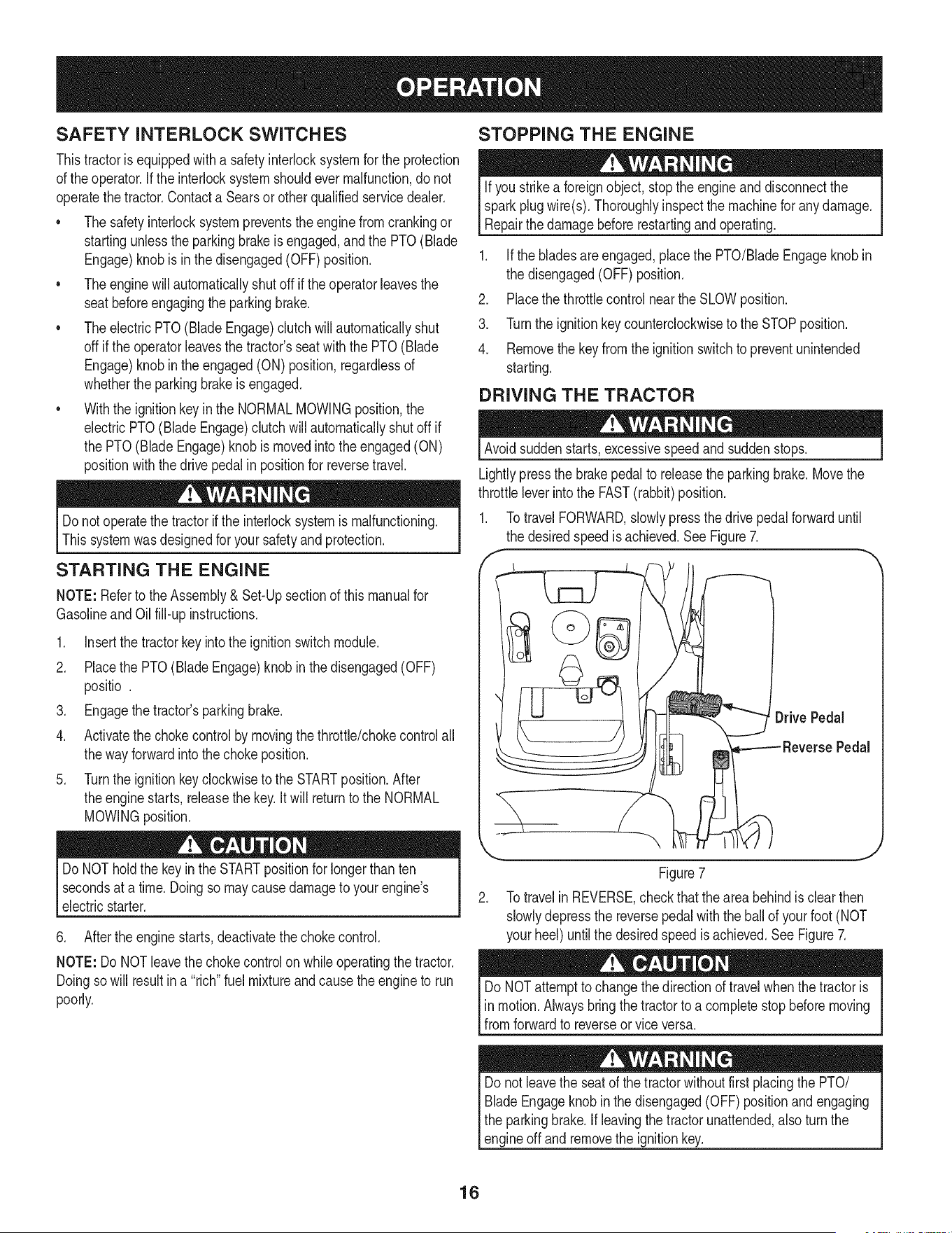
1. TotravelFORWARD,slowlypressthe drivepedal forwarduntil
the desiredspeed is achieved.SeeFigure7.
,
ReversePedal
Figure7
2. Totravelin REVERSE,checkthatthe area behindisclearthen
slowlydepressthe reversepedal with the ballof yourfoot(NOT
your heel) untilthe desiredspeedis achieved.SeeFigure7.
DoNOTattemptto changethe directionof travelwhenthetractoris
inmotion.Alwaysbringthe tractorto a completestop beforemoving
fromforwardto reverseor vice versa.
Donot leavethe seatof the tractorwithoutfirst placingthe PTO/
BladeEngageknobinthe disengaged(OFF)positionandengaging
the parkingbrake.If leavingthe tractorunattended,alsoturn the
engineoff andremovethe ignitionkey.
16
REVERSE CAUTION MODE
The REVERSECAUTIONMODEpositionof thekeyswitch module
allowsthe tractorto beoperatedinreversewiththe blades(PTO)
engaged.
NOTE: Mowingin reverseis not recommended.
Useextremecautionwhile operatingthe tractorin the REVERSE
CAUTIONMODE.Alwayslookdownand behindbeforeandwhile
backing.Do notoperatethe tractorwhenchildrenor othersare
around.Stopthe tractorimmediatelyif someoneentersthearea.
Touse the REVERSECAUTIONMODE:
NOTE:The operatorMUSTbe seatedin the tractorseat.
DRIVING ON SLOPES
Referto the SLOPEGUIDEon page8 to help determineslopeswhere
you mayoperatethe tractorsafely.
Donot mowon inclineswitha slopeinexcessof 15degrees(a rise
approximately2-1/2feet every 10feet).The tractorcouldoverturnanc
causeseriousinjury.
• Mowupand down slopes,NEVERacross.
• Exerciseextremecautionwhenchangingdirectionon slopes.
• Watchfor holes,ruts,bumps,rocks,or otherhiddenobjects.
Uneventerraincouldoverturnthe machine.Tallgrass can hide
obstacles.
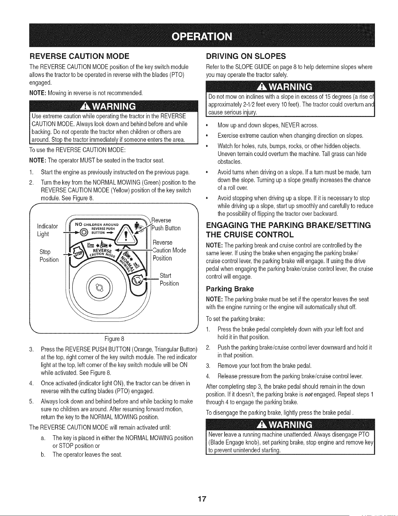
1. Start theengineas previouslyinstructedon the previouspage. •
2. Turnthe key from the NORMALMOWING(Green)positionto the
REVERSECAUTIONMODE(Yellow)positionof the keyswitch
module.SeeFigure8.
, _"_ Reverse
i_Push Button
II1Reverse
Mode
Position
Start
Position
Stop
Position
\ j
Figure8
3. Pressthe REVERSEPUSHBUTTON(Orange,TriangularButton)
at the top,rightcornerof the key switchmodule.The redindicator
lightat the top,leftcornerof the key switchmodulewillbe ON
whileactivated.See Figure8.
4. Onceactivated(indicatorlightON),the tractorcan bedrivenin
reversewiththe cuttingblades(PTO)engaged.
5. Alwayslookdownand behindbeforeandwhilebackingto make
surenochildrenare around.Afterresumingforwardmotion,
returnthe keyto the NORMALMOWINGposition.
The REVERSECAUTIONMODEwill remainactivateduntil:
a. Thekeyis placedin eitherthe NORMALMOWINGposition
orSTOPpositionor
b. Theoperatorleavestheseat.
Avoidturnswhendrivingon a slope.If a turnmustbe made,turn
downthe slope.Turningupa slopegreatly increasesthe chance
of a rollover.
Avoidstoppingwhen drivingup a slope.If it is necessaryto stop
whiledrivingup a slope,start upsmoothlyandcarefullyto reduce
the possibilityof flippingthe tractoroverbackward.
ENGAGING THE PARKING BRAKE/SETTING
THE CRUISE CONTROL
NOTE:Theparkingbreakandcruisecontrolarecontrolledbythe
samelever.Ifusingthe brakewhenengagingthe parkingbrake/
cruisecontrollever,theparkingbrakewillengage.Ifusingthe drive
pedalwhenengagingthe parkingbrake/cruisecontrollever,the cruise
controlwill engage.
Parking Brake
NOTE:Theparkingbrakemustbesetif theoperatorleavesthe seat
withthe engine runningor theenginewillautomaticallyshutoff.
To set the parkingbrake:
1. Pressthe brakepedal completelydownwith yourleftfoot and
holditinthat position.
2. Pushthe parkingbrake/cruisecontrolleverdownwardandholdit
inthatposition.
3. Removeyourfootfromthe brakepedal.
4. Releasepressurefromthe parkingbrake/cruisecontrollever.
Aftercompletingstep3, the brakepedalshouldremaininthe down
position.If itdoesn't,the parkingbrakeisnot engaged.Repeatsteps1
through4 toengagethe parkingbrake.
Todisengagethe parkingbrake,lightly pressthe brakepedal.
(BladeEngageknob),set parkingbrake,stopengineand remove
to preventunintendedstarting.
17
Cruise Control
Neverengagethe cruise controlleverwhiletravelingin reverse.
Tosetthe cruisecontrol:
1. Slowlypressthe upperportionof thedrive pedalwithyour right
footuntilthe desiredspeedisachieved.
2. Lightlypressthe parkingbrake/cruisecontrolleverdownwardand
holdit in thatposition.
3. Removeyour footfromthe drive pedal.
4. Releasepressurefromthe parkingbrake/cruisecontrollever.
Aftercompletingstep 3, the drivepedal shouldremainin the down
positionandthetractorwill maintainthe sameforwardspeed.If it
doesn't,the cruisecontrolis not engaged.Repeatsteps 1 through4 to
engagethecruisecontrol.
Todisengagethe cruisecontrol,lightlypressthe drivepedalor the
brakepedal.
NOTE:Cruisecontrolcannotbesetat the tractor'sfastestground
speed.If the operatorshouldattemptto do so,thetractorwill automati-
callydecelerateto thefastestoptimalmowinggroundspeed.
Tochangethe directionof travelfrom forwardto reversewhencruise
controlis engaged,pressthe brakepedal to disengagethe cruise
controlandbring the tractorto a completestop.Thenslowlypressthe
reversepedalwiththe ballof yourfootto travelinreverse.
USING THE DECK LIFT LEVER
To raisethe cuttingdeck,movethe deck lift leverto the left,then place
it in the notchbestsuitedfor yourapplication.
OPERATING THE HEADLIGHTS
The lampsare ONwheneverthe ignitionkey is rotatedout of the STOP
position.The lampsturnOFFwhenthe ignitionkeyis movedto the
STOPposition.
ENGAGING THE PTO
Engagingthe PTOtransferspowerto thecuttingdeckor other
(separatelyavailable)attachments.Toengagethe PTO:
1. Movethe Throttle/Chokecontrolleverto the FAST(rabbit)
position.
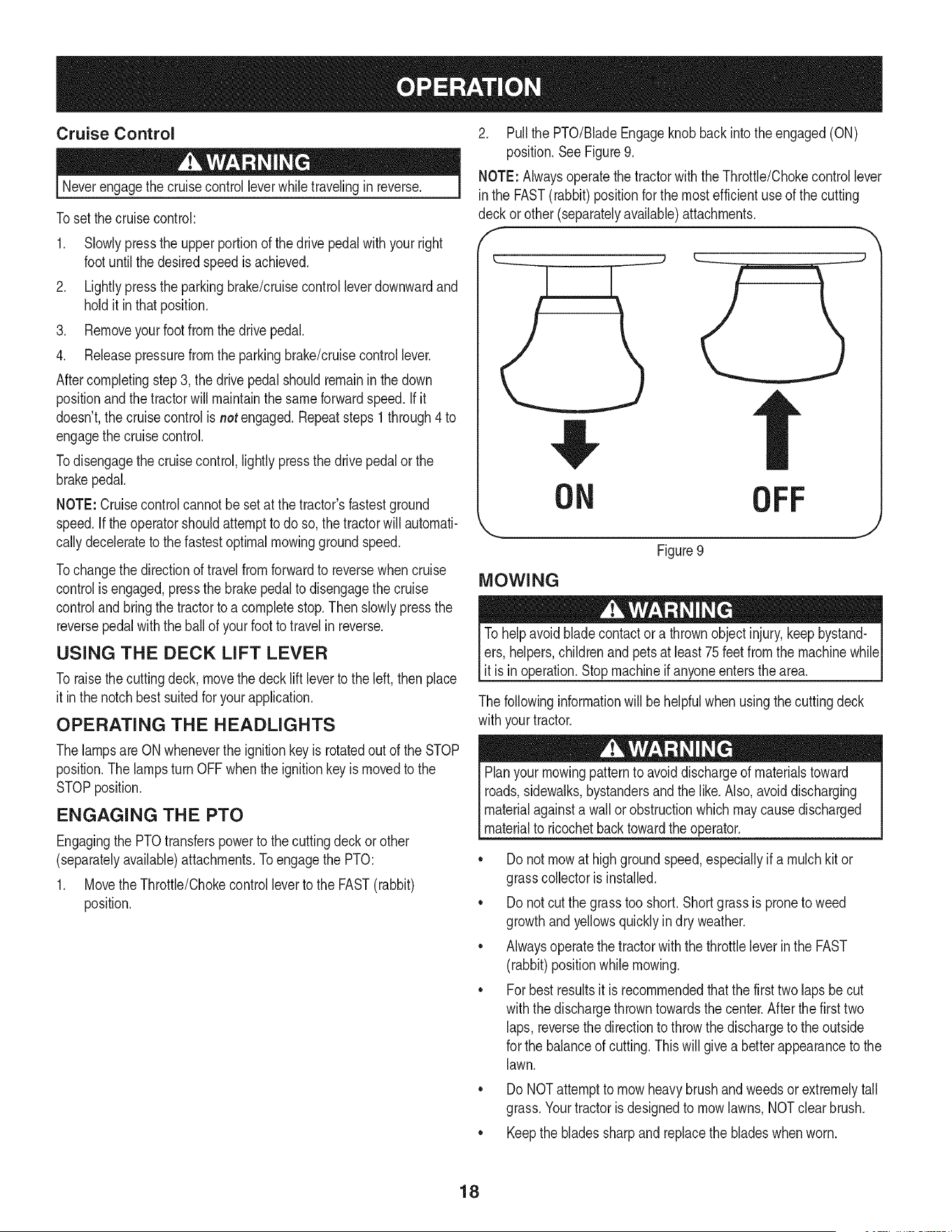
2. Pullthe PTO/BladeEngageknob backinto theengaged(ON)
position.SeeFigure9.
NOTE: Alwaysoperatethe tractorwith the Throttle/Chokecontrollever
in the FAST(rabbit)positionfor the mostefficientuseof the cutting
deckor other(separatelyavailable)attachments.
f -,
ON OFF
Figure9
MOWING
To helpavoidbladecontactor a thrownobject injury,keepbystand-
ers,helpers,childrenand petsat least75 feet from the machinewhile
it is in operation.Stopmachineif anyoneentersthe area.
The followinginformationwill behelpfulwhenusingthe cuttingdeck
withyourtractor.
Planyourmowingpatternto avoiddischargeof materialstoward
roads,sidewalks,bystandersand the like.Also,avoiddischarging
materialagainstawall orobstructionwhichmaycausedischarged
materialto ricochetbacktowardthe operator.
• Donot mowat highgroundspeed,especiallyif a mulchkit or
grasscollectoris installed.
• Donot cutthe grasstooshort. Shortgrassis proneto weed
growthand yellowsquicklyin dry weather.
• Alwaysoperatethetractorwiththe throttleleverinthe FAST
(rabbit)positionwhilemowing.
• Forbestresultsit is recommendedthat the first two laps becut
withthe dischargethrowntowardsthe center.Afterthe firsttwo
laps, reversethedirectionto throwthe dischargeto theoutside
for the balanceof cutting.Thiswill givea better appearanceto the
lawn.
Do NOTattemptto mowheavy brushand weedsorextremelytall
grass.Yourtractoris designedto mowlawns,NOTclearbrush.
• Keepthe bladessharpandreplacethe bladeswhenworn.
18
Beforeperforminganytypeof maintenance/service,disengageall
controlsandstoptheengine.Waituntilallmovingpartshavecometo
acompletestop.Disconnectsparkplugwireandgroundit againstthe
engineto preventunintendedstarting.Alwayswearsafetyglassesduring
operationorwhileperforminganyadjustmentsor repairs.
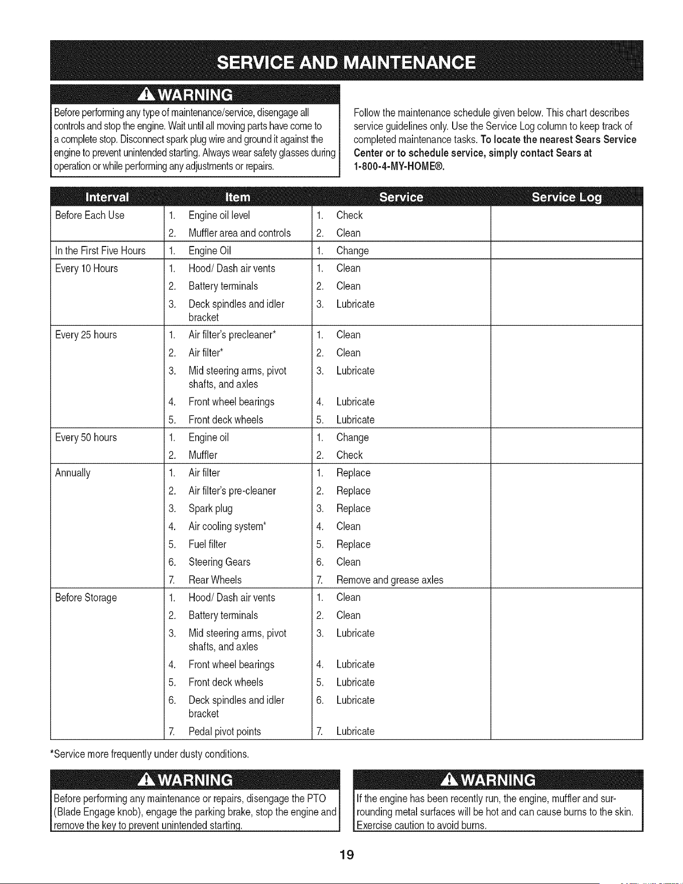
Followthe maintenanceschedulegivenbelow.Thischart describes
serviceguidelinesonly.Usethe ServiceLogcolumnto keeptrackof
completedmaintenancetasks.To locate the nearest Sears Service
Centeror to scheduleservice,simplycontactSears at
1-800-4-MY-HOME®.
BeforeEachUse
In the First FiveHours
Every10Hours
Every25 hours
Every50 hours
Annually
BeforeStorage
1. Engineoil level
2. Mufflerareaandcontrols
1. EngineOil
1. Hood/Dash air vents
2. Batteryterminals
3. Deckspindlesandidler
bracket
1. Air filter'sprecleaner*
2. Air filter*
3. Mid steeringarms,pivot
shafts,andaxles
4. Frontwheelbearings
5. Frontdeck wheels
1. Engineoil
2. Muffler
1. Air filter
2. Air filter'spre-cleaner
3. Sparkplug
4. Air coolingsystem*
5. Fuelfilter
6. SteeringGears
7. RearWheels
1. Hood/Dash air vents
2. Batteryterminals
3. Mid steeringarms,pivot
shafts,and axles
4. Frontwheelbearings
5. Frontdeck wheels
6. Deckspindlesandidler
bracket
7. Pedalpivot points
1. Check
2. Clean
1. Change
1. Clean
2. Clean
3. Lubricate
1. Clean
2. Clean
3. Lubricate
4. Lubricate
5. Lubricate
1. Change
2. Check
1. Replace
2. Replace
3. Replace
4. Clean
5. Replace
6. Clean
7. Removeandgreaseaxles
1. Clean
2. Clean
3. Lubricate
4. Lubricate
5. Lubricate
6. Lubricate
7. Lubricate
*Servicemorefrequentlyunderdustyconditions.
_reventunintendedstartin(
Ifthe enginehas beenrecentlyrun,the engine,mufflerand sur-
roundingmetalsurfaceswill be hot andcancauseburnsto the skin.
Exercisecautionto avoidburns.
19
CUTTING DECK REMOVAL
1. Placethe PTO/BladeEngageknobin the disengaged(OFF)
positionandengagethe parkingbrake.
2. Lowerthe deck by movingthe deck lift leverintothe bottomnotch
onthe rightfender.
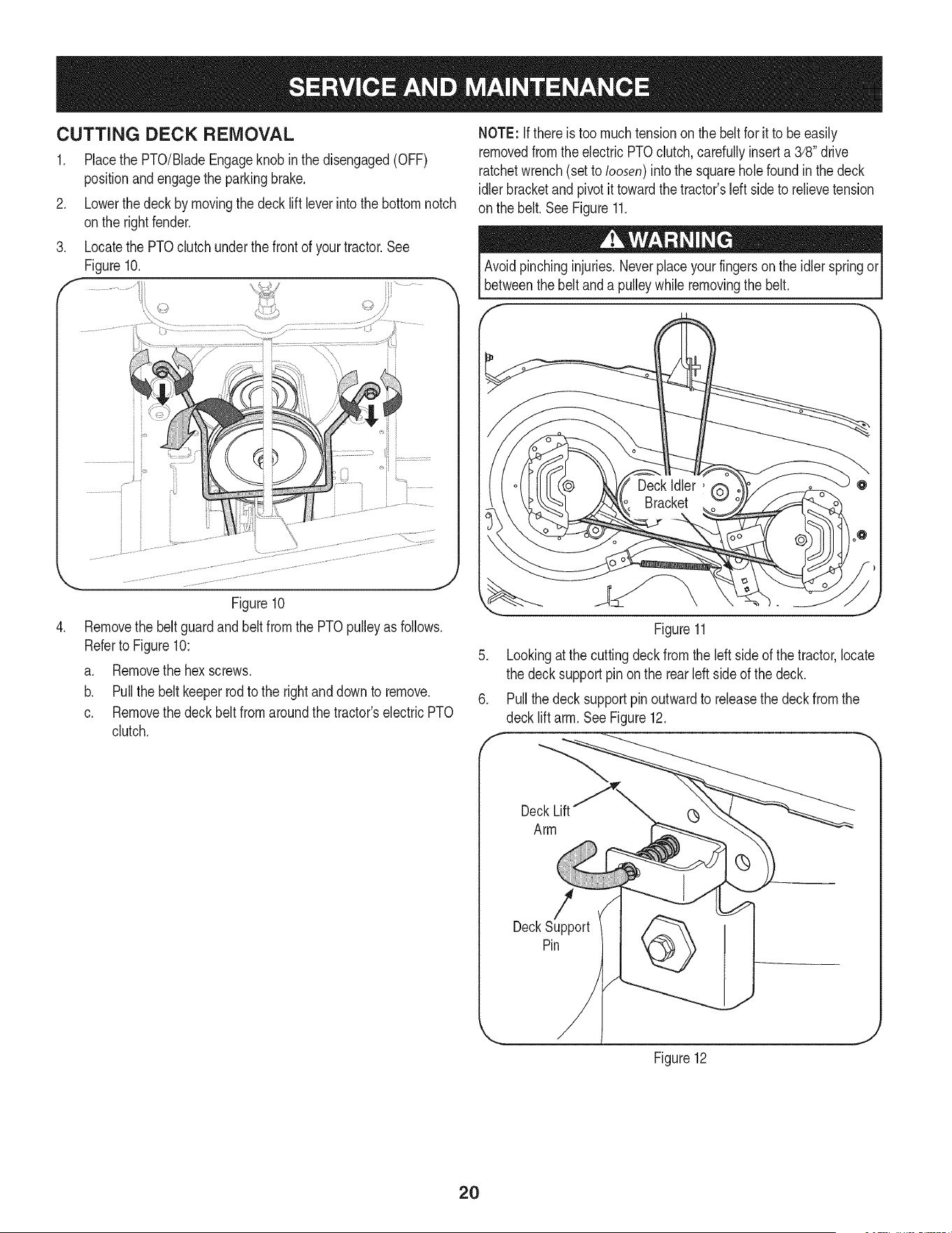
3. Locatethe PTOclutchunderthe frontof yourtractor.See
Figure10.
:td
.
Figure10
Removethe beltguardand beltfrom the PTOpulleyas follows.
Referto Figure10:
a. Removethe hexscrews.
b. Pull the beltkeeperrod to the rightanddownto remove.
c. Removethe deck belt fromaroundthe tractor'selectricPTO
clutch.
NOTE: If there is too muchtensionon thebelt for it to be easily
removedfromthe electricPTOclutch,carefullyinsert a 3/8" drive
ratchetwrench(set to loosen)intothe squareholefound inthe deck
idlerbracketand pivotit towardthe tractor'sleftside to relievetension
on the belt. See Figure11.
Avoidpinchinginjuries.Neverplaceyourfingersonthe idlerspringor
betweenthe beltand a pulleywhileremovingthe belt.
Figure11
5. Lookingat thecuttingdeckfromthe leftside of thetractor,locate
the deck supportpin on the rearleft sideof thedeck.
6. Pullthe deck supportpinoutwardto releasethe deckfrom the
decklift arm.SeeFigure12.
DeckLift (_
Arm
DeckPinSupport
Figure12
2O
.
8.
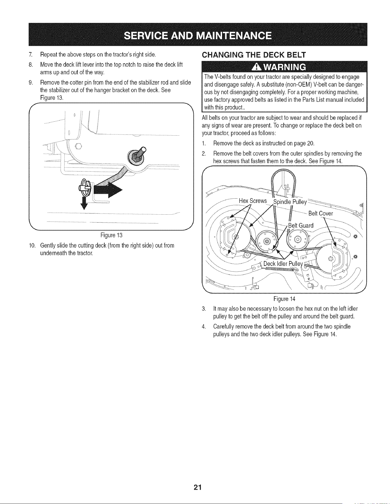
.
f
Figure13
10. Gentlyslidethe cuttingdeck (from the rightside)out from
underneaththe tractor.
J
CHANGING THE DECK BELT
TheV-beltsfoundon yourtractorarespeciallydesignedto engage
anddisengagesafely.A substitute(non-OEM)V-beltcan bedanger-
ous by notdisengagingcompletely.Fora properworkingmachine,
use factoryapprovedbeltsas listedin the PartsList manualincluded
withthis product..
All beltsonyourtractoraresubjectto wearandshouldbereplacedif
any signsof wear are present.Tochangeor replacethe deckbelt on
yourtractor,proceedas follows:
1. Removethe deckas instructedon page20.
2. Removethe beltcoversfromtheouter spindlesby removingthe
hexscrewsthatfastenthem to the deck.SeeFigure14.
.....HexScrews 3indlePulle'
Figure14
3. Itmay alsobe necessaryto loosenthe hexnut onthe left idler
pulleyto get the beltoff the pulleyandaroundthe belt guard.
4. Carefullyremovethe deck belt fromaroundthe two spindle
pulleysandthe two deck idler pulleys.SeeFigure14.
21
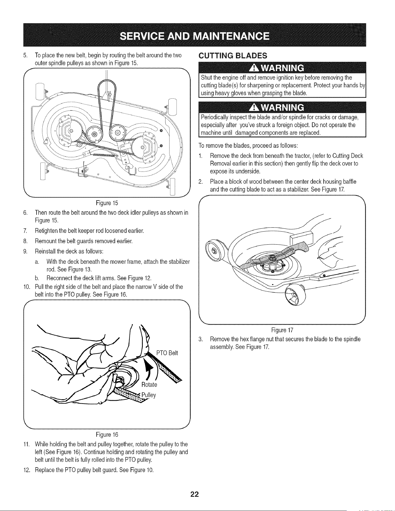
.
Toplacethe newbelt,beginby routingthe belt aroundthe two
outerspindlepulleysas shownin Figure15.
CUTTING BLADES
Shutthe engineoff and removeignitionkeybeforeremovingthe
cuttingblade(s)for sharpeningor replacement.Protectyourhands
usingheavygloveswhengraspingthe blade.
Figure15
6. Thenroutethe beltaroundthe twodeckidlerpulleysas shownin
Figure15.
7. Retightenthe belt keeperrodloosenedearlier.
8. Remountthebelt guardsremovedearlier.
9. Reinstallthe deckas follows:
a. Withthe deck beneaththe mowerframe,attachthe stabilizer
rod. See Figure13.
b. Reconnectthedeck liftarms.SeeFigure12.
10. Pull the rightside ofthe beltandplacethe narrowV side of the
belt intothe PTOpulley.See Figure16.
!ey
PTOBelt
Periodicallyinspectthe bladeand/orspindlefor cracksor damage,
especiallyafter you'vestrucka foreignobject.Do notoperatethe
machineuntil damagedcomponentsare replaced.
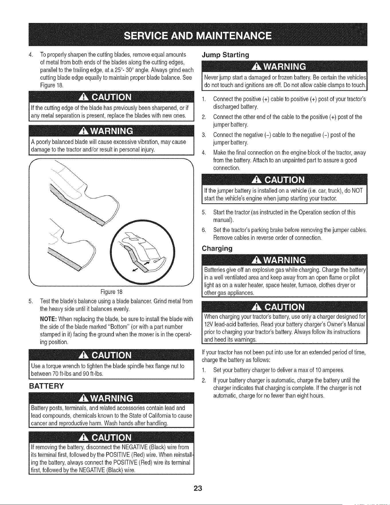
To removethe blades,proceedas follows:
1. Removethe deckfrombeneaththe tractor,(referto CuttingDeck
Removalearlierin thissection)then gentlyflip the deckoverto
exposeits underside.
2. Placea blockof woodbetweenthe centerdeck housingbaffle
andthe cuttingbladeto act as a stabilizer.See Figure17.
Figure17
3. Removethe hexflangenut that securesthe bladeto the spindle
assembly.See Figure17.
J
Figure16
11. Whileholdingthe beltand pulleytogether,rotatethepulleyto the
left(See Figure16).Continueholdingand rotatingthe pulleyand
belt untilthe beltis fully rolledinto the PTOpulley.
12. Replacethe PTOpulleybelt guard.SeeFigure10.
22
4. Jump Starting
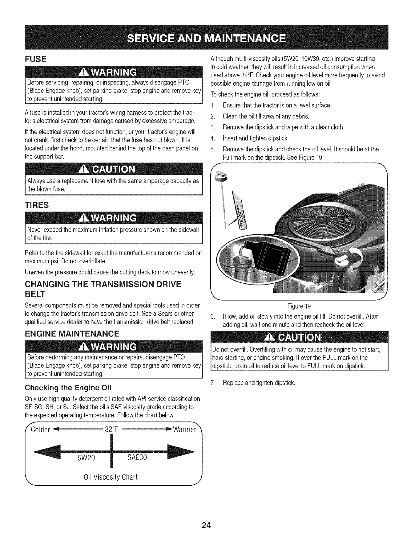
Toproperlysharpenthe cuttingblades,removeequalamounts
of metalfrom both endsof the bladesalongthe cuttingedges,
parallelto thetrailingedge,at a 250.300angle.Alwaysgrindeach
cuttingbladeedgeequallyto maintainproperblade balance.See
Figure18.
Neverjump starta damagedor frozenbattery.Becertainthe vehicles
do nottouchandignitionsareoff. Donot allowcableclampsto touch.
Ifthe cuttingedgeof the bladehas previouslybeensharpened,orif
any metal separationis present,replacethe bladeswithnewones.
A poorlybalancedblade willcauseexcessivevibration,may cause
damageto the tractorand/or resultinpersonalinjury.
.
Figure18
Testthe blade'sbalanceusinga bladebalancer.Grindmetalfrom
the heavyside untilit balancesevenly.
NOTE:Whenreplacingthe blade,besureto installthe bladewith
the sideof the blademarked"Bottom" (or witha partnumber
stampedin it) facingthe groundwhenthe moweris in the operat-
ingposition.
Useatorquewrenchto tightenthe bladespindlehexflange nutto
between70ft-lbs and 90 ft-lbs.
BATTERY
Batteryposts,terminals,andrelatedaccessoriescontainleadand
leadcompounds,chemicalsknownto the Stateof Californiato cause
cancerand reproductiveharm.Washhandsafterhandling.
If removingthe battery,disconnectthe NEGATIVE(Black)wirefrom
itsterminalfirst,followedby the POSITIVE(Red)wire. Whenreinstall-
ingthe battery,alwaysconnectthe POSITIVE(Red)wireits terminal
first,followedby the NEGATIVE(Black)wire.
1. Connectthe positive(+) cableto positive(+) postof yourtractor's
dischargedbattery.
2. Connectthe otherendof the cableto thepositive(+) postof the
jumperbattery.
3. Connectthe negative(-) cable to the negative(-) postof the
jumperbattery.
4. Makethefinal connectionon the engineblockof thetractor,away
fromthe battery.Attachto an unpaintedpart to assurea good
connection.
Ifthejumperbatteryis installedona vehicle(i.e.car,truck),do NOT
start the vehicle'senginewhenjump startingyourtractor.
5. Startthe tractor(as instructedin theOperationsectionof this
manual).
6. Setthe tractor'sparkingbrakebeforeremovingthejumpercables.
Removecablesinreverseorderof connection.
Charging
Batteriesgiveoff an explosivegas whilecharging.Chargethe batteryI
in a wellventilatedareaand keepawayfroman openflame or pilot I
lightas on a waterheater,spaceheater,furnace,clothesdryeror I
othergas appliances. ..J
Whenchargingyourtractor'sbattery,use onlya chargerdesignedfor
12Vlead-acidbatteries.Readyourbatterycharger'sOwner'sManual
priorto chargingyourtractor'sbattery.Alwaysfollow its instructions
andheed its warnings.
Ifyourtractorhas notbeenput intouse for anextendedperiodof time,
chargethe batteryas follows:
1. Setyourbatterychargerto delivera max of 10amperes.
2. Ifyour batterychargeris automatic,chargethe batteryuntilthe
chargerindicatesthatchargingis complete.If thechargeris not
automatic,chargefor nofewer thaneighthours.
23
FUSE
Beforeservicing,repairing,or inspecting,alwaysdisengagePTO
(BladeEngageknob),set parkingbrake,stopengineand remove
to preventunintendedstarting.
Afuse is installedin yourtractor'swiringharnessto protectthe trac-
tor'selectricalsystemfrom damagecausedbyexcessiveamperage.
Ifthe electricalsystemdoesnot function,or yourtractor'senginewill
notcrank,first checkto becertain that the fusehasnot blown.It is
locatedunderthe hood,mountedbehindthe top of the dashpanelon
the supportbar.
Althoughmulti-viscosityoils (5W20,10W30,etc.) improvestarting
incold weather,theywill resultin increasedoil consumptionwhen
usedabove32°RCheckyourengineoil levelmorefrequentlyto avoid
possibleenginedamagefrom runninglowon oil.
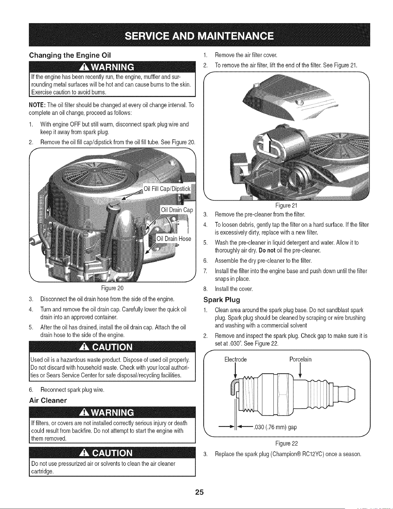
Tocheckthe engineoil, proceedas follows:
1. Ensurethatthetractoris on a levelsurface.
2. Cleanthe oilfill areaof any debris.
3. Removethe dipstickand wipewitha cleancloth.
4. Insertandtightendipstick.
5. Removethe dipstickand checkthe oil level.It shouldbe at the
Fullmarkon thedipstick.SeeFigure19.
Alwaysusea replacementfusewiththe sameamperagecapacity as
the blownfuse.
TIRES
Neverexceedthe maximuminflationpressureshownon the sidewall
of thetire.
Referto the tire sidewallfor exacttire manufacturer'srecommendedor
maximumpsi. Donot overinfiate.
Uneventire pressurecouldcausethecuttingdeckto mow unevenly.
CHANGING THE TRANSMISSION DRIVE
BELT
Severalcomponentsmustberemovedand specialtools usedin order
to changethe tractor'stransmissiondrive belt.Seea Searsor other
qualifiedservicedealerto havethe transmissiondrivebelt replaced.
ENGINE MAINTENANCE
Beforeperformingany maintenanceor repairs,disengagePTO
(BladeEngageknob),set parkingbrake,stopengineand remove
to preventunintendedstarting.
Checking the Engine Oil
Onlyuse highqualitydetergentoil ratedwith APIserviceclassification
SF,SG,SH,or SJ.Selectthe oil's SAEviscositygradeaccordingto
theexpectedoperatingtemperature.Followthe chart below.
,E _Warmer_
Colder _ 32°F
Figure19
6. Iflow, add oil slowlyintothe engineoil fill. Donot overfill.After
addingoil, wait one minuteand then recheckthe oil level.
Do notoverfill.Overfillingwithoil maycausethe engineto not start,
hardstarting,or enginesmoking.If overthe FULL markon the
dipstick,drain oil to reduceoil levelto FULLmark on dipstick.
7. Replaceandtightendipstick.
5W20
Oil Viscosity Chart
24
Changing the Engine Oil
Ifthe enginehas beenrecentlyrun,the engine,mufflerand sur-
roundingmetalsurfaceswill be hotandcan causeburnsto the skin.
Exercisecautionto avoidburns.
NOTE:The oilfilter shouldbechangedat every oil changeinterval.To
completean oil change,proceedasfollows:
1. With engineOFF butstill warm,disconnectsparkplugwire and
keepit awayfromspark plug.
2. Removetheoil fill cap/dipstickfrom the oil fill tube.See Figure20.
Figure20
1. Removethe airfiltercover.
2. To removethe air filter,lift theendof the filter.See Figure21.
Figure21
3. Disconnectthe oil drainhosefrom the side of theengine.
4. Turnand removethe oil drain cap. Carefullylowerthe quickoil
drainintoanapprovedcontainer.
5. After theoil hasdrained,installthe oildrain cap. Attachthe oil
drainhoseto the sideof the engine.
Usedoil is a hazardouswasteproduct.Disposeof usedoil properly.
Donotdiscardwith householdwaste.Checkwithyourlocalauthori-
tiesor SearsServiceCenterfor safedisposal/recyclingfacilities.
6. Reconnectsparkplug wire.
Air Cleaner
if filters, or coversarenot installedcorrectlyseriousinjuryor death
could resultfrom backfire.Do notattemptto startthe enginewith
them removed.
Do notuse pressurizedair or solventsto cleanthe aircleaner
cartridge.
3. Removethe pre-cleanerfrom the filter.
4. To loosendebris,gently tap thefilterona hardsurface.If thefilter
isexcessivelydirty, replacewitha newfilter.
5. Washthe pre-cleanerin liquiddetergentand water.Allowit to
thoroughlyair dry.Do not oil the pre-cleaner.
6. Assemblethe dry pre-cleanerto the filter.
7. Installthe filter intothe enginebaseand pushdownuntilthe filter
snapsinplace.
8. Installthe cover.
Spark Plug
1. Cleanareaaroundthe sparkplugbase.Donot sandblastspark
plug.Sparkplug shouldbecleanedby scrapingor wirebrushing
andwashingwith a commercialsolvent
2. Removeandinspectthe sparkplug.Checkgapto make sureit is
setat .030".SeeFigure22.
Electrode Porcelain
!
"4"='_.030 (.76ram)gap
Figure22
3. Replacethe sparkplug (Champion®RC12YC)oncea season.
25
Fuel Filter IVluffler
Gasolineand itsvaporsare extremelyflammableandexplosive.Fire
orexplosioncan causesevereburnsor death.
• Keepgasolineawayfromsparks,openflames,pilotlights,heat,
andotherignitionsources.
• Checkfuel lines,tank,cap,and fittingsfrequentlyforcracks
or leaks.Replaceif necessary.Seea Searsor otherqualified
servicedealerto replacefuel line.
• Beforereplacingthe fuelfilter,drainthe fueltankor closethe fuel
shut-offvalve.
• Replacementpartsmustbethe sameand installedin the same
positionas theoriginalparts.
• Iffuel spills,wait until it evaporatesbeforestartingengine.
To Drainthe Fuel:
1. Locatethe fuelfilter,which is routedon the leftsideof the engine
betweenthe fuel tankandthecarburetor,and may be attachedto
theenginewitha tie strap.
2. Cut the tie strap,if present,then pinchthe in-lineclampon the
fuelfilterwitha pairof pliers.
3. Slidethe clampup the fuel line.
4. Removethe in-linefuel lineanddrainthe fuel intoan approved
container.
To Replace the Fuel Filter:
1. Beforereplacingthe fuelfilter,drainthe fueltankor closethe fuel
shut-offvalve.Otherwise,fuel can leakout andcausea fire or
explosion.
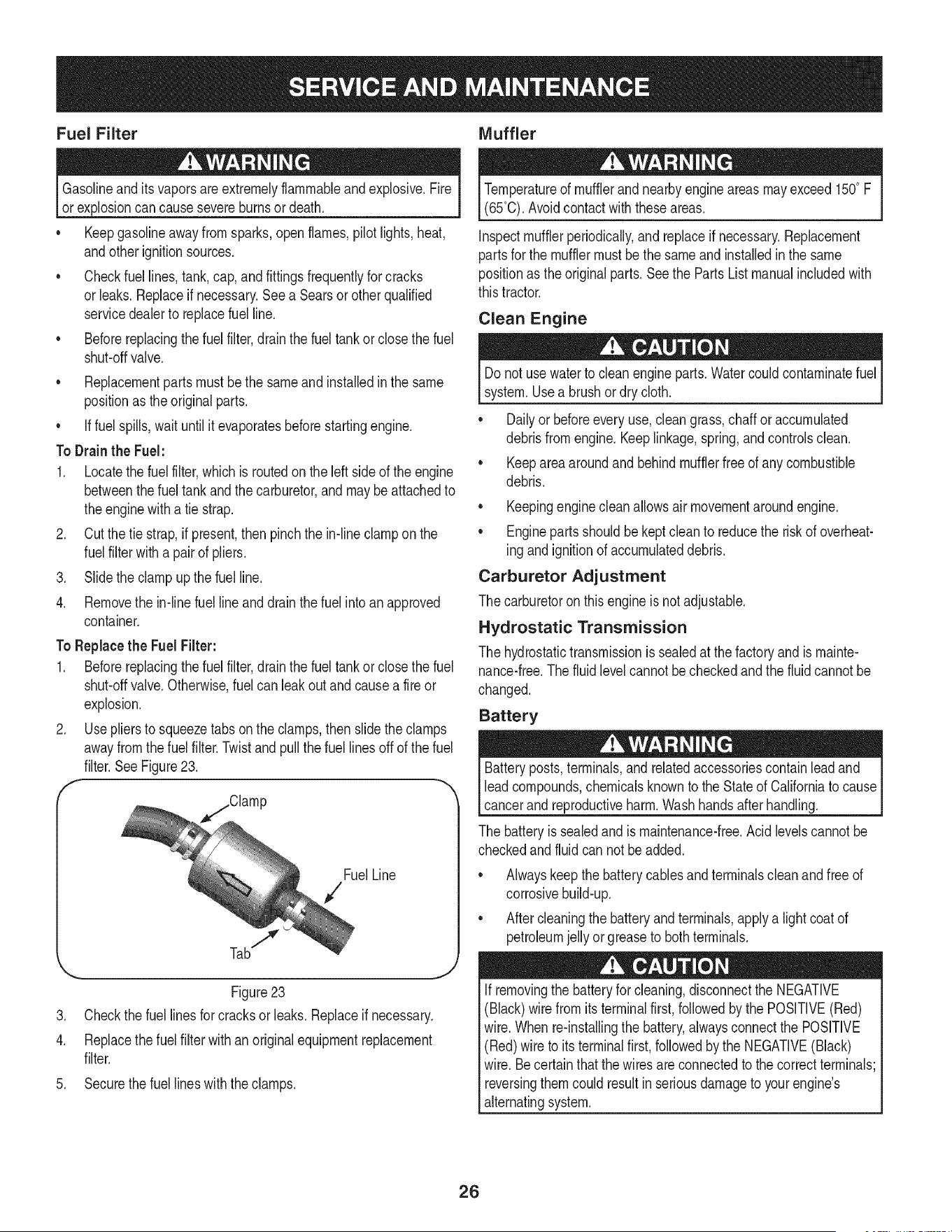
2. Use pliersto squeezetabsonthe clamps,then slidethe clamps
awayfromthefuel filter.Twistand pullthefuel linesoff of the fuel
filter.SeeFigure23.
f
FuelLine
.
4.
.
7
,,,..,., ,,J
Figure23
Checkthe fuel linesfor cracksor leaks.Replaceif necessary.
Replacethe fuel filterwithan originalequipmentreplacement
filter.
Securethe fuel lineswiththe clamps.
Temperatureof mufflerandnearbyengineareasmay exceed150° F
(65°0).Avoidcontactwith these areas.
Inspectmufflerperiodically,and replaceif necessary.Replacement
partsfor the mufflermustbethe sameand installedin the same
positionas the originalparts.Seethe Parts List manualincludedwith
thistractor.
Clean Engine
Donot usewaterto clean engineparts.Watercouldcontaminatefuel
system.Usea brushor dry cloth.
Dailyor beforeevery use,cleangrass,chaffor accumulated
debrisfromengine.Keeplinkage,spring,and controlsclean.
Keepareaaroundand behindmufflerfreeof anycombustible
debris.
Keepingenginecleanallowsair movementaroundengine.
• Enginepartsshouldbekeptcleanto reducethe risk of overheat-
ing andignitionof accumulateddebris.
Carburetor Adjustment
The carburetoron this engine is notadjustable.
Hydrostatic Transmission
The hydrostatictransmissionis sealedat thefactory and is mainte-
nance-free.The fluidlevelcannotbecheckedand the fluidcannotbe
changed.
Battery
Batteryposts,terminals,and relatedaccessoriescontainleadand
leadcompounds,chemicalsknownto the Stateof Californiato cause
cancerand reproductiveharm.Washhandsafterhandling.
The batteryis sealedand is maintenance-free.Acidlevelscannotbe
checkedand fluid can notbe added.
Alwayskeepthe batterycablesand terminalscleanandfree of
corrosivebuild-up.
• Aftercleaningthe batteryandterminals,applya lightcoatof
petroleumjelly or greaseto bothterminals.
Ifremovingthe batteryfor cleaning,disconnectthe NEGATIVE
(Black)wirefromitsterminalfirst,followedby the POSITIVE(Red)
wire.Whenre-installingthe battery,alwaysconnectthe POSITIVE
(Red)wire to its terminalfirst, followedbythe NEGATIVE(Black)
wire.Becertainthatthe wiresareconnectedto thecorrectterminals;
reversingthemcouldresultin seriousdamageto yourengine's
alternatingsystem.
26
CLEANING THE TRACTOR
Anyfuel oroil spilledonthe machineshouldbe wipedoff promptly.Do
NOTallowdebristo accumulatearoundthecoolingfins of the engine,
the transmission'scoolingfanor on any otherpartof themachine,
especiallythebelts and pulleys.
Deck Wash System
Yourtractor'sdeckis equippedwitha waterporton its surfaceas part
of its deckwash system.
Usethedeckwashto rinsegrassclippingsfromthe deck'sunderside
andpreventthe buildupof corrosivechemicals.Completethe following
stepsAFTEREACHMOWING:
1. Drivethe tractorto a level,clearspotonyour lawn,near enough
for yourgardenhoseto reach.
Makecertainthe tractor'sdischargechuteis directedAWAYfromyour
house,garage,parkedcars,etc.
2. Disengagethe PTO(BladeEngage),set the parkingbrakeand
stoptheengine.
3. Threadthe hosecoupler(packagedwithyourtractor'sOperator's
Manual)ontothe endof yourgardenhose.
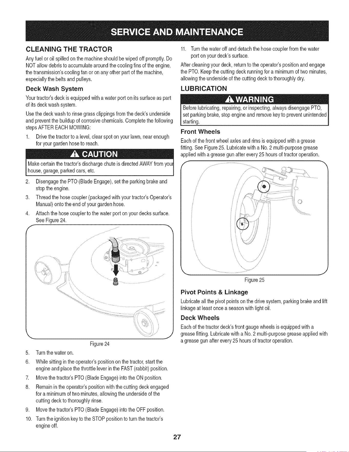
4. Attachthe hosecouplerto the waterport on yourdecks surface.
SeeFigure24.
Figure24
5. Turnthe wateron.
6. Whilesittingin theoperator'spositiononthe tractor,startthe
engineandplacethe throttleleverinthe FAST(rabbit)position.
7. Movethe tractor'sPTO(BladeEngage)intothe ONposition.
8. Remainin the operator'spositionwiththecuttingdeckengaged
for a minimumof two minutes,allowingthe undersideof the
cuttingdeckto thoroughlyrinse.
9. Movethe tractor'sPTO(BladeEngage)intothe OFF position.
10. Turnthe ignitionkeyto the STOPpositionto turnthe tractor's
engineoff.
11. Turnthewateroff and detach thehose couplerfromthe water
portonyour deck'ssurface.
Aftercleaningyourdeck, returnto the operator'spositionandengage
the PTO. Keepthe cuttingdeckrunningfor a minimumof two minutes,
allowingthe undersideof the cuttingdeck to thoroughlydry.
LUBRICATION
Beforelubricating,repairing,orinspecting,alwaysdisengagePTO,
set parkingbrake,stop engineandremovekeyto preventunintended
starting.
Front Wheels
Eachof thefront wheelaxlesand rims is equippedwitha grease
fitting.See Figure25. Lubricatewitha No.2 multi-purposegrease
appliedwitha greasegunafter every25 hoursof tractoroperation.
\
Figure25
Pivot Points & Linkage
Lubricateallthe pivot pointson the drivesystem,parkingbrakeandlift
linkageat leastonce a seasonwith lightoil.
Deck Wheels
Eachof thetractordeck'sfrontgaugewheelsisequippedwitha
greasefitting.Lubricatewitha No.2 multi-purposegreaseappliedwith
a greasegunafterevery25 hoursof tractoroperation.
27
ADJUSTMENTS
Shutthe engineoff, removethe ignitionkeyandengagethe parking
brakebeforemakingadjustments.Protectyour handsby usingheavy
gloveswhenhandlingthe blades.
NOTE:Checkthe tractor'stire pressurebeforeperforminganydeck
levelingadjustments.Referto Tireson page24 for informationregard-
ingtire pressure.
Leveling the Deck (Front To Rear)
Thefrontof the cuttingdeck is supportedby a stabilizerbarthatcan
beadjustedto levelthe deckfromfront to rear.Thefront of the deck
shouldbebetween1/4-inchand3/8-inchlowerthanthe rearof the
deck.Adjustif necessaryas follows:
1. Parkthe tractorparkedona firm,level surfaceandplacethe deck
lift leverinthe middleposition.
2. Rotatethe blade nearestthe dischargechutecoverso that it is
parallelwiththe tractor.
3. Measurethe distancefrom the frontof the bladetip to the ground
andthe rearof the bladetip to the ground.The firstmeasurement
takenshouldbebetween1/4"and 3/8" lessthan the second
measurement.
Determinetheapproximatedistancenecessaryfor properadjustment
and proceed,if necessary.
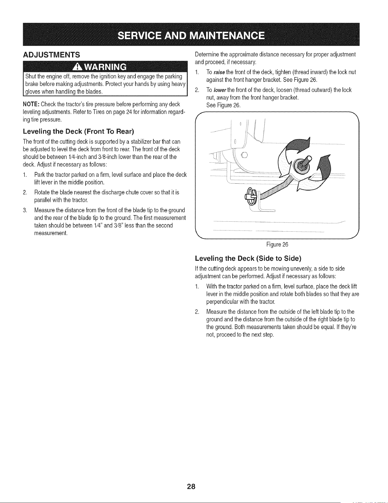
1. To raisethe frontof the deck,tighten(threadinward)the locknut
againstthe front hangerbracket.See Figure26.
2. To lowerthe frontof the deck,loosen(threadoutward)the lock
nut,awayfrom the fronthangerbracket.
See Figure26.
f
Figure26
J
Leveling the Deck (Side to Side)
Ifthe cuttingdeckappearsto be mowingunevenly,a sideto side
adjustmentcan be performed.Adjustif necessaryas follows:
1. With the tractorparkedona firm, levelsurface,placethe decklift
leverin the middlepositionand rotatebothbladesso thattheyare
perpendicularwiththe tractor.
2. Measurethedistancefromthe outsideof the left bladetip to the
groundandthe distancefrom the outsideof the rightblade tip to
the ground.Bothmeasurementstaken shouldbe equal.Ifthey're
not, proceedto the nextstep.
28
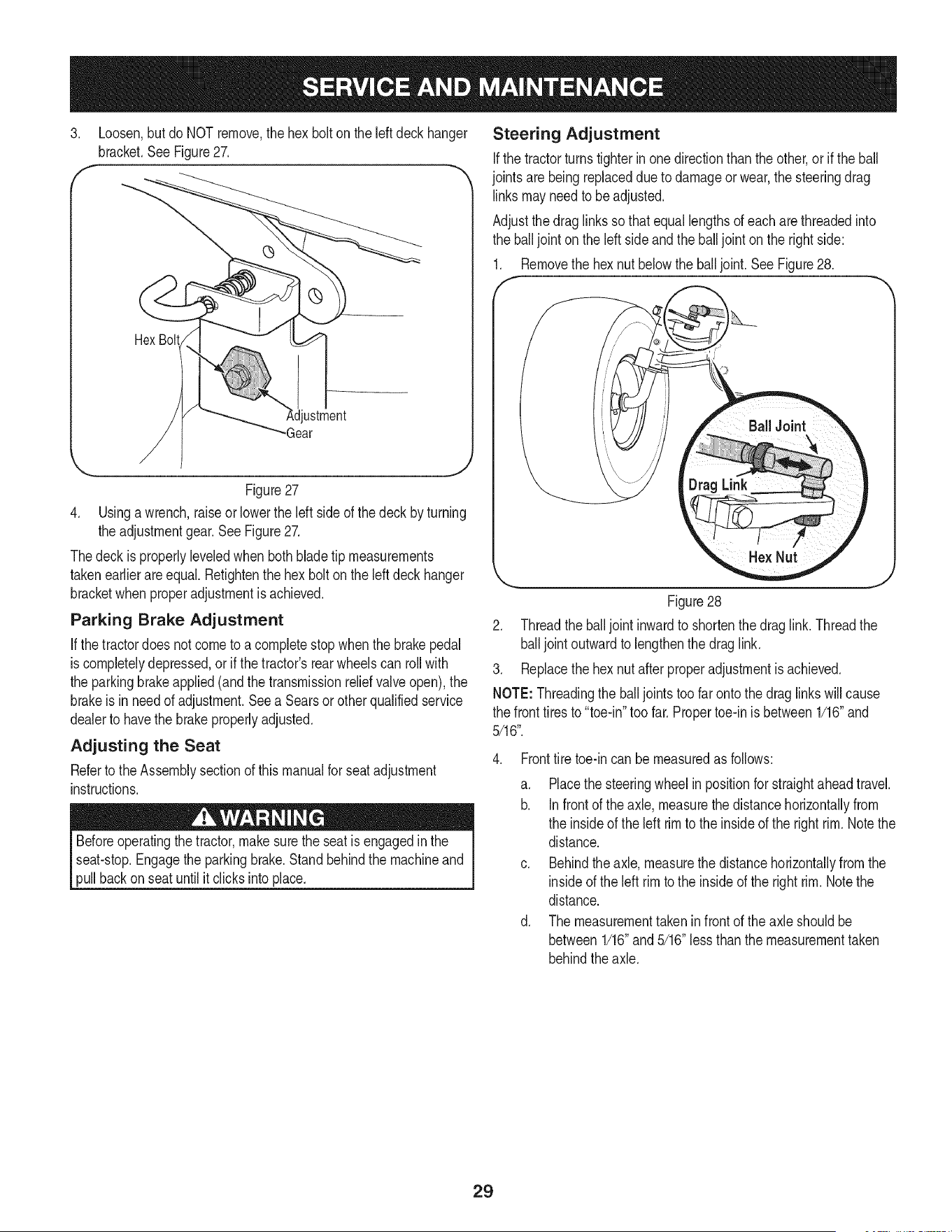
3. Loosen,butdo NOT remove,the hexbolt on the leftdeck hanger
bracket.SeeFigure27.
f
Hex Bolt
ustment
-Gear
Figure27
4. Usinga wrench,raiseor lowerthe Idt side of thedeck byturning
the adjustmentgear.See Figure27.
Thedeckis properlyleveledwhenbothblade tip measurements
takenearlierareequal. Retightenthe hexbolt on the leftdeckhanger
bracketwhenproperadjustmentis achieved.
Parking Brake Adjustment
If thetractordoes notcometo acompletestopwhenthe brakepedal
is completelydepressed,or if the tractor'srearwheelscan rollwith
the parkingbrakeapplied(andthe transmissionreliefvalve open),the
brakeis in needof adjustment.Seea Searsorother qualifiedservice
dealerto havethe brakeproperlyadjusted.
Adjusting the Seat
Referto the Assemblysectionof thismanualfor seat adjustment
instructions.
Beforeoperatingthe tractor,make surethe seatis engagedinthe
seat-stop.Engagethe parkingbrake.Standbehindthe machineand
pullbackon seat untilit clicksinto place.
Steering Adjustment
Ifthe tractorturnstighterin one directionthanthe other,or if the ball
jointsarebeingreplaceddue to damageorwear,the steeringdrag
linksmayneedto beadjusted.
Adjustthedraglinks so thatequallengthsof each arethreadedinto
the ball joint onthe left sideandthe balljoint on the rightside:
1. Removethe hexnut belowthe balljoint. See Figure28.
J
Figure28
2. Threadthe balljoint inwardto shortenthe draglink. Threadthe
balljoint outwardto lengthenthe draglink.
3. Replacethe hexnut afterproperadjustmentis achieved.
NOTE:Threadingthe balljoints toofar ontothe draglinkswillcause
the front tires to "toe-in"too far.Propertoe-inis between1/16"and
5/16".
4. Fronttire toe-incan be measuredas follows:
a. Placethe steeringwheel inpositionfor straightaheadtravel.
b. Infrontof the axle, measurethe distancehorizontallyfrom
the insideof the left rimto the insideof the right rim.Notethe
distance.
c. Behindthe axle,measurethe distancehorizontallyfrom the
insideof the left rimto the insideof the rightrim. Notethe
distance.
d. The measurementtakenin front of the axle shouldbe
between1/16"and5/16"lessthan themeasurementtaken
behindthe axle.
29
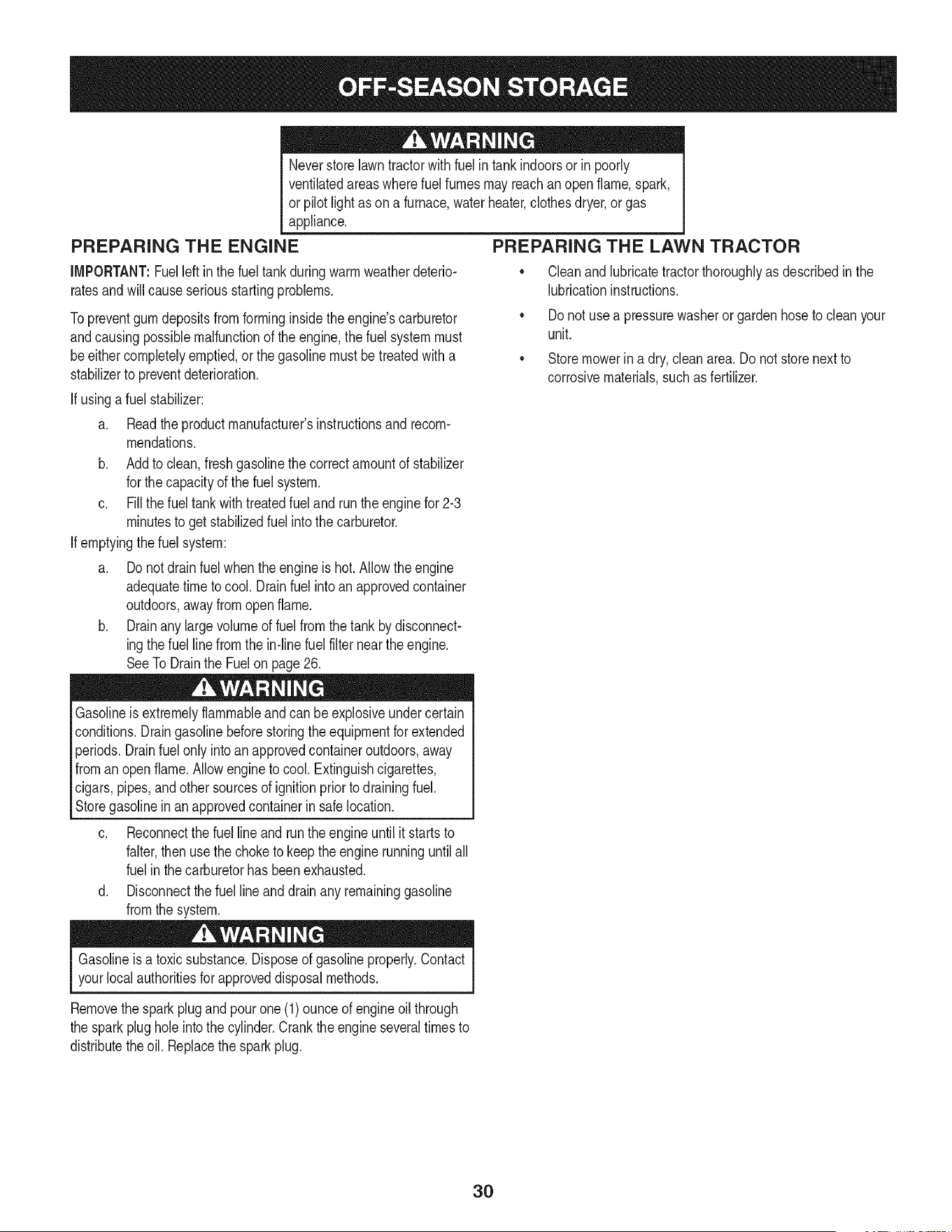
Neverstorelawntractorwith fuelin tankindoorsor in poorly
ventilatedareaswherefuel fumesmayreachan openflame,spark,
or pilot lightas ona furnace,waterheater,clothesdryer,or gas
appliance,
PREPARING THE ENGINE
IMPORTANT:Fuelleft in the fueltankduringwarmweatherdeterio-
ratesandwill causeseriousstartingproblems.
Topreventgum depositsfromforminginsidetheengine'scarburetor
andcausingpossiblemalfunctionof the engine,the fuel systemmust
beeithercompletelyemptied,or thegasolinemustbetreatedwitha
stabilizerto preventdeterioration.
If usingafuel stabilizer:
a. Readthe productmanufacturer'sinstructionsand recom-
mendations.
b. Add to clean,freshgasolinethe correctamountof stabilizer
for thecapacityof the fuel system.
c. Fill thefuel tankwithtreatedfueland run theenginefor 2-3
minutesto get stabilizedfuel intothe carburetor.
If emptyingthefuel system:
a. Do notdrainfuel whentheengineis hot.Allowtheengine
adequatetimeto cool. Drainfuel intoan approvedcontainer
outdoors,awayfromopen flame.
b. Drainany largevolumeof fuelfromthe tank by disconnect-
ingthe fuel linefromthe in-line fuelfilternear theengine.
SeeToDrainthe Fuelonpage26.
Gasolineis extremelyflammableand can beexplosiveundercertain
conditions.Draingasolinebeforestoringtheequipmentfor extended
periods.Drainfuelonly intoan approvedcontaineroutdoors,away
fromanopenflame.Allowengine to cool.Extinguishcigarettes,
cigars,pipes,andother sourcesof ignitionpriorto drainingfuel.
Storegasolinein an approvedcontainerin safelocation.
c. Reconnectthe fuellineand run theengineuntilit startsto
falter,then usethe choketo keepthe enginerunninguntilall
fuelin the carburetorhasbeenexhausted.
d. Disconnectthe fuel line and drainany remaininggasoline
fromthe system.
PREPARING THE LAWN TRACTOR
• Cleanandlubricatetractorthoroughlyas describedin the
lubricationinstructions.
• Do notuse a pressurewasheror gardenhoseto cleanyour
unit.
• Storemowerina dry,cleanarea.Do not storenext to
corrosivematerials,suchas fertilizer.
Gasolineis a toxicsubstance.Disposeof gasolineproperly.Contact
yourlocal authoritiesfor approveddisposal methods.
Removethespark plug and pour one (1)ounceof engine oil through
the sparkplug hole intothe cylinder.Crankthe engineseveraltimesto
distributetheoil. Replacethe sparkplug.
30
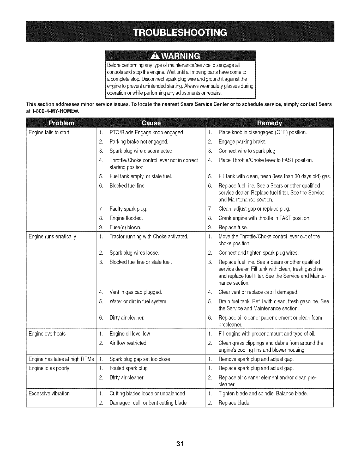
Beforeperforminganytypeof maintenance/service,disengageall
controlsandstoptheengine.Waituntilallmovingpartshavecometo
a completestop.Disconnectsparkplugwireandgroundit againstthe
engineto preventunintendedstarting.Alwayswearsafetyglassesduring
operationorwhileperforminganyadjustmentsor repairs.
Thissectionaddresses minorserviceissues.Tolocate the nearestSears Service Centeror to scheduleservice,simplycontactSears
at 1-800-4-MY-HOME®.
1. PTO/BladeEngageknobengaged.
2. Parkingbrakenotengaged.
3. Sparkplugwire disconnected.
4. Throttle/Chokecontrollevernot incorrect
startingposition.
5. Fueltankempty,or stale fuel.
Enginefailsto start
6. BIockedfuel line.
7. Faultysparkplug.
8. Engineflooded.
9. Fuse(s)blown.
1. Tractorrunningwith Chokeactivated.
2. Sparkplugwiresloose.
3. Blockedfuel lineor stalefuel.
4. Ventingas cap plugged.
5. Wateror dirt in fuel system.
Dirtyair cleaner.
Enginerunserratically
6. 6.
Engineoverheats 1. Engineoil levellow 1.
2. Air flow restricted 2.
Enginehesitatesat high RPMs 1. Sparkpluggap settooclose 1. Remove
Engineidlespoorly 1. Fouledsparkplug 1. Replace
2. Dirtyair cleaner 2. Replace
cleaner.
1. Placeknobindisengaged(OFF)position.
2. Engageparkingbrake.
3. Connectwireto sparkplug.
4. PlaceThrottle/Chokeleverto FASTposition.
5. Filltankwith clean, fresh(less than 30days old) gas.
6. Replacefuel line.Seea Searsor otherqualified
servicedealer.Replacefuel filter.Seethe Service
andMaintenancesection.
7. Clean,adjustgap or replaceplug.
8. Crankenginewith throttlein FASTposition.
9. Replacefuse.
1. Movethe Throttle/Chokecontrolleverout of the
chokeposition.
2. Connectandtightenspark plugwires.
3. Replacefuel line.Seea Searsor otherqualified
servicedealer.Filltankwithclean,freshgasoline
andreplacefuel filter.Seethe Serviceand Mainte-
nancesection.
4. Clearventor replacecap if damaged.
5. Drainfueltank. Refillwith clean,fresh gasoline.See
theServiceand Maintenancesection.
Replaceair cleanerpaper elementor cleanfoam
precleaner.
Fillenginewith properamountandtype of oil.
Cleangrass clippingsand debrisfromaroundthe
engine'scoolingfins and blowerhousing.
sparkplugand adjustgap.
sparkplugand adjustgap.
air cleanerelementand/orcleanpre-
Excessivevibration 1. Cuttingbladeslooseor unbalanced 1. Tightenbladeand spindle.Balanceblade.
2. Damaged,dull,or bentcuttingblade 2. Replaceblade.
31
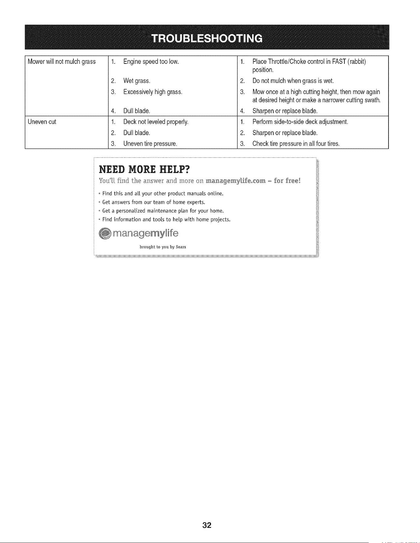
Mowerwill not mulchgrass
Unevencut
1. Enginespeedtoo low.
2. Wetgrass.
3. Excessivelyhigh grass.
4. Dullblade.
1. Decknot leveledproperly.
2. Dullblade.
3. Uneventire pressure.
1. PlaceThrottle/Chokecontrolin FAST(rabbit)
position.
2. Do notmulchwhengrass is wet.
3. Mowonce at a highcuttingheight,then mowagain
at desiredheightor makea narrowercuttingswath.
4. Sharpenor replaceblade.
1. Performside-to-sidedeckadjustment.
2. Sharpenor replaceblade.
3. Checktire pressurein all four tires.
o Find information and tools to help with home projects.
32

Congratulationson makinga smartpurchase.YournewCraftsman@
productis designedandmanufacturedfor yearsof dependableopera-
tion.But likeall products,it mayrequirerepairfromtimeto time.That's
whenhavinga RepairProtectionAgreementcansave youmoneyand
aggravation.
Here'swhatthe RepairProtectionAgreement*includes:
* Expert service byour 10,000professionalrepairspecialists
o Unlimitedserviceand no chargefor partsand laboron all
coveredrepairs
o Product replacementupto $1500if yourcoveredproductcan't be
fixed
• Discountof 10%from regularprice of serviceand relatedinstalled
partsnotcoveredby theagreement;also,10%off regularpriceof
preventivemaintenancecheck
• Fast help by phone- we call it RapidResolution- phonesupport
froma Searsrepresentative.Thinkof usas a "talkingowner's
manual."
Onceyou purchasethe Agreement,a simplephonecall is all that it
takesfor youto scheduleservice.Youcan call anytimedayor night,or
schedulea serviceappointmentonline.
The RepairProtectionAgreementis a risk-freepurchase.If youcancel
for any reasonduringthe productwarrantyperiod,wewill providea full
refund.Or,a proratedrefundanytimeafter the productwarrantyperiod
expires.Purchaseyour RepairProtectionAgreementtoday!
Somelimitationsand exclusionsapply. For pricesand additional
informationin the U.S.A.call 1-800-827-6655.
*Coverage in Canadavaries on some items. Forfull details call
Sears Canadaat 1-800-361-6665.
Sears Installation Service
ForSearsprofessionalinstallationof homeappliances,garagedoor
openers,waterheaters,and othermajorhomeitems,in the U.S.A.or
Canadacall 1-800-4-MY-HOME®.
33
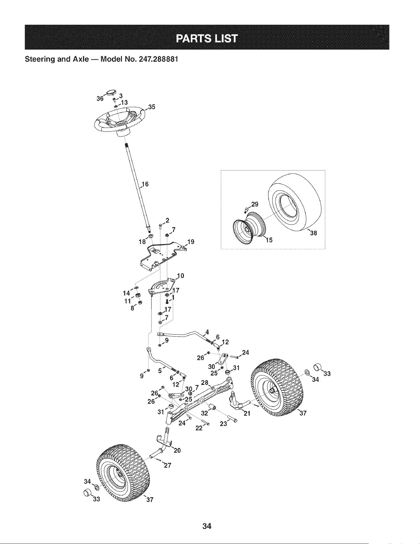
Steering and Axle B IViodel No. 247.288881
36"%3
.... ..35
9
4
3205-"_.31
28
31
34
34

Steering and Axle B Model No. 247.288881
710-04095 HexHeadScrew,3/8-16:1.00 638-04022-0637 RHAxleAssembly
2 710-0514 HexHeadScrew,3/8-16:1.00 i21 638-04028-0637 LHAxle Assembly
3 710-0643 HexHeadScrew,5/16-18:1.00 22 i710-0395 HexHeadScrew,5/16-18:2.25
4 711-04998 iLH DragLink 23 710-0859 Hex HeadScrew,3/8-16:2.50
5 711-04999 iRH DragLink 24 710-3180 Hex HeadScrew,5/16-18:1.75
6 912-0240 iJamNut,7/16-20 25 912-0214 HexlockNut,3/8-24
7 712-04065 iFlangelockNut,3/8-16 26 712-04063 FlangelockNut,5/16-18
8 712-0459 iFlangelockNut,7/16-20 27 714-0162 CotterPin,5/32:1.25
9 712-3004A iFlangelockNut,5/16-18 28 719-04413A PivotBarAxle
10 717-1550F iSteeringGear 29 934-0255 TubelessAir Valve
11 717-1554 iSteeringPinionGear 30 748-04065-0637 SteeringBlock
12 923-0448A iBallJoint,7/16-20 31 748-04068 Spacer,.71ID X .125OD X .56LG
13 936-3004 FlatWasher,.406X .875X .105 32 750-05280 Spacer,.385X 1.00X 1.5075
14 736-3084 FlatWasher,.51X 1.12X .06:HT 33 731-05674 BumperCap
15 634-04405-4042 RimAssembly 34 736-04228A FlatWasher,.7811Dx1.5900D
16 738-04263 iSteeringShaft,.625OD X24.25LG 35 631-04415 SteeringWheel
17 738-04363 ShoulderSpacer,.385X1.25X .3025 i36 731-06825 SteeringWheelCap
18 741-04237B iHexFlangeBearing5/8 PM 37 i634-04406-0961 WheelAssembly
19 783-06043-0637 ISteeringSupportBracket i38 734-1731-0901 Tire
35
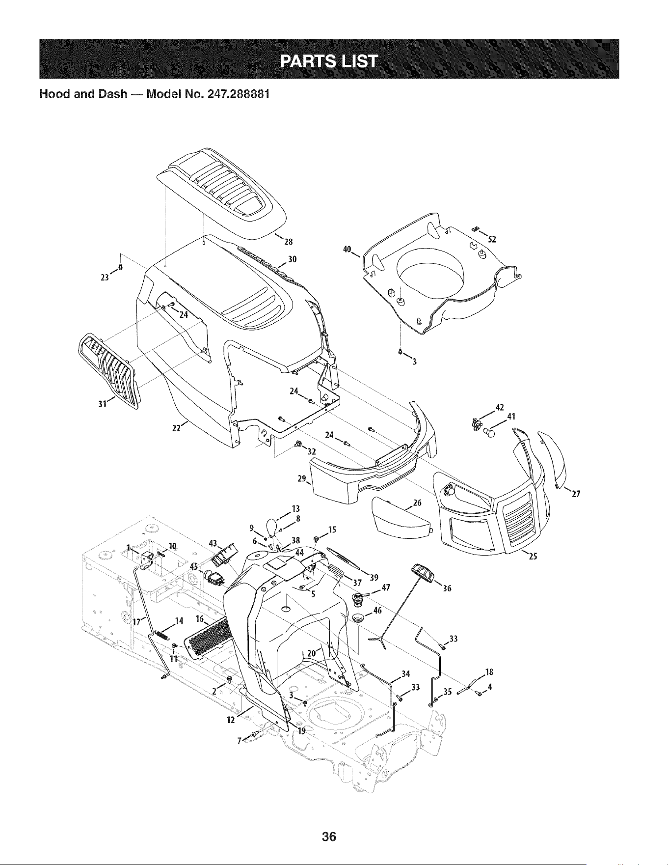
Hood and Dash B IViodel No. 247.288881
28
3O
\
13
8
38
/4
12
3G

Hood and Dash B Model No. 247.288881
631-04353A DashLever 931-07457 Grill
2 710-04484 TaptiteScrew,LockWasher,5/16-18:.750 i26 731-07458 RHLens
3 710-0599 TaptiteScrew,LockWasher,1/4-20:0.500 i27 731-07459 LHLens
4 710-0895 Hi-LoScrew,LockWasher,1/4-15:0.750 i28 931-07461 HoodScoop
5 710-1652 Screw,LockWasher,1/4-20:0.625 i29 731-07467 LowerGrill
6 710-1017 Screw,1/4-14:0.625 i30 731-07469 LHHoodScoop
7 710-1611B TaptiteScrew,5/16-18:0.750 i31 731-07470 RH HoodScoop
8 710-3217 MachineScrew,#8-32:0.375 i32 738-04091A ShoulderScrew,.43X.29:TT:5/16-18
9 712-0142 HexNut,#8-32:GRA i33 710-0642 TaptiteScrew,1/4-20:0.750
10 714-04040 Bow-tieCotterPin i34 747-05049 RHTankSupportRod
11 726-3046 RatchetClip:.250DIA i35 747-05050 LHTankSupportRod
12 731-07456 Dash i36 951-12179 FuelCap
13 731-07550 ControlKnob i37 951-11650 FuelTank,2.06 GallonsCARB
14 732-04580 ExtensionSpring,.500 DIAX 2.733LG i38 946-04621 Throttle/ChokeControl
15 735-0271A Bumper i39 735-04170 FuelTankGasket
16 735-04076 AccessoryNet i40 731-07495 P-StylePlen
17 747-05280 ControlRodLatch i41 925-0963 MiniatureLamp,12V
18 747-1196 LeverRod i42 925-1649 LampSocket
19 783-04285F-0637RHDashSupportPlate i43 725-04992 SwitchKeyModule
20 783-04323F-0637LH DashSupportPlate 44 925-04036C HourMeter
21 625-04124 Keys(Setof 2)not shown i45 725-04258 PTOSwitch
22 683-04618-0691 HoodAssembly i46 735-04081 RubberGrommet
23 710-04187 Hi-loScrew,Lock Washer,1/4-15:0.50 i47 751-12118 Fuel RolloverValve
24 710-05108 Screw,LockWasher,1/4 DIA:.750
37
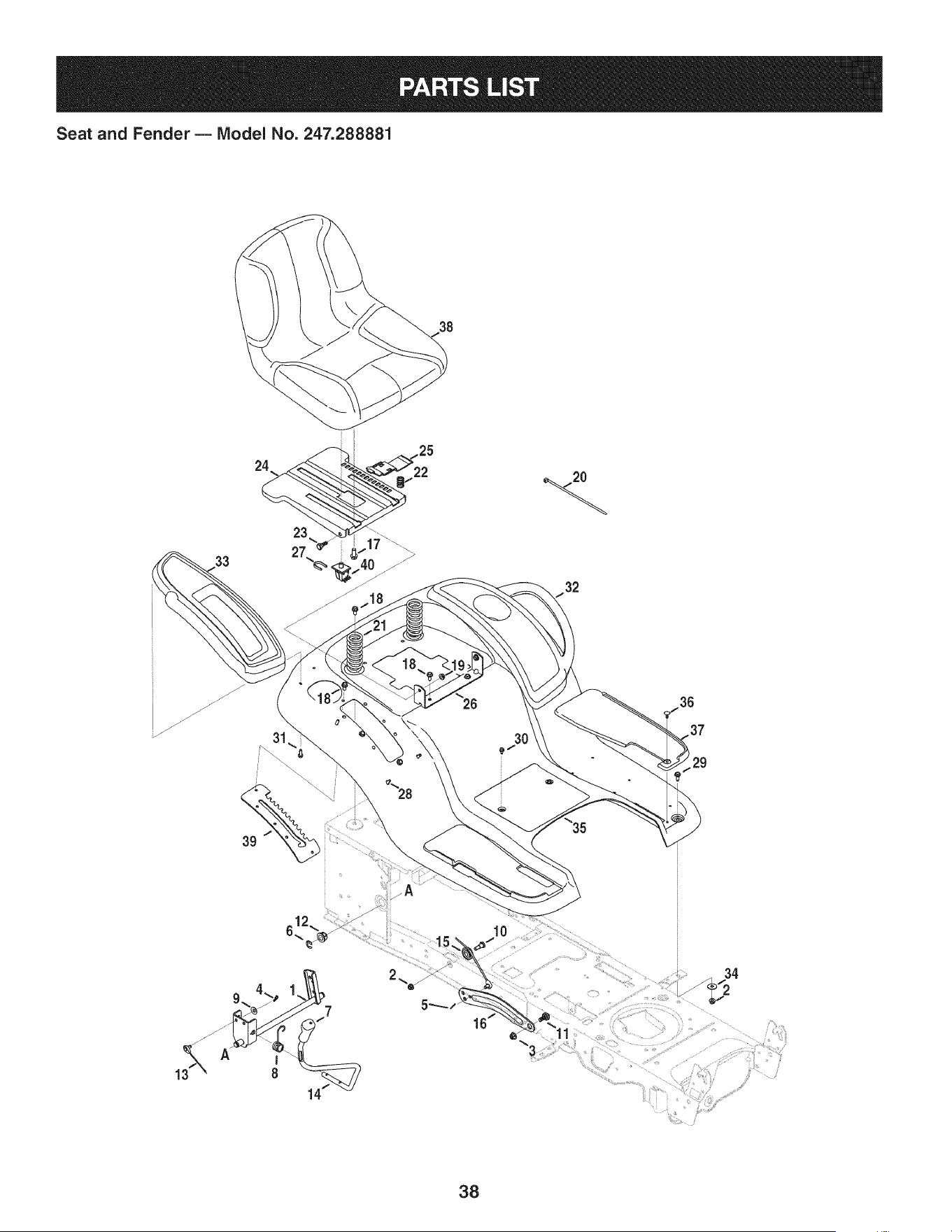
Seat and Fender B IViodel No. 247.288881
38
24
32
3O
36
34
38

Seat and Fender B Model No. 247.288881
683-04223-0637 LiftShaft Assembly 732-04563 CompressionSpring,.68X 1.065X .055
2 712-04063 FlangelockNut,5/16-18 i23 938-0296 ShoulderScrew,.437X .268:5/16-18
3 712-04065 FlangelockNut,3/8-16 i24 783-06049-0691 Seat MountingBracket
4 914-0104 CotterPin,.072DIA.X 1.13LG i25 783-06050 SeatAdjustmentLever
5 714-04040 Bow-TieCotterPin i26 783-06088-0691 Seat PivotBracket
6 716-0106A E-Ring,.625DIA.SHAFT i27 783-06448 SwitchRetainerClip
7 720-04150 HandleGrip i28 710-04187 Hi-LoScrew,LockWasher,1/4-15:0.50
8 732-0874 TorsionSpring i29 710-0451 CarriageBolt,5/16-18:.750
9 736-0105 SpringWasher,.401X .870X .063 i30 710-0599 TaptiteScrew,LockWasher,1/4-20:0.500
10 738-0138A ShoulderScrew, .437X .470:5/16-18 i31 710-0895 Hi-LoScrew,LockWasher,1/4-15:0.750
11 938-0380 ShoulderBolt,.500X.270:3/8-16 i32 731-05837 LH FenderCover
12 941-0225 Hex FlangeBearing i33 731-06754 RHFenderCover
13 746-0968 Lift Cable,16.16LG i34 736-3078 FlatWasher,.344X 1.00X .063HDN
14 747-04962A Lift Handle i35 783-06118-0691 Fender
15 756-04331 PulleyRollerCable i36 726-3046 RatchetClip
16 783-05546A-0637LiftArm i37 735-04137 LH FootPad
17 710-04482 HexHeadFlange,3/8-16:.875 -- 735-04139 RH FootPad
18 710-04484 TaptiteScrew,LockWasher,5/16-18:.750 i38 757-04127 Seat
19 712-3004A FlangelockNut,5/16-18 i39 783-06181-0637 Lift Bracket
20 725-0157 CableTie, 3/16X .05X 7.4 i40 925-05013 Seat Switch
21 732-04561 CompressionSpring,1.71X 3.735X .238
3g
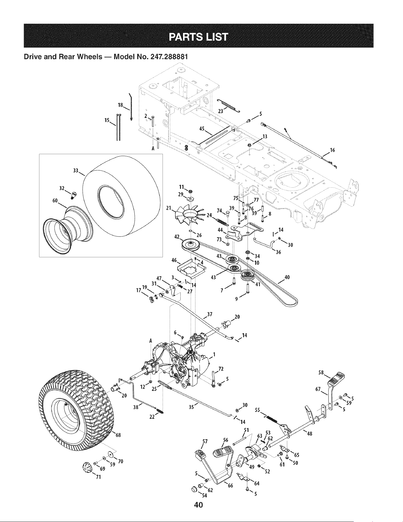
Drive and Rear Wheels B IViodel No. 247.288881
37 20
2O
A
72
14
5
57 56
/
51
4O
55
61
58
67

Drive and Rear Wheels B Model No. 247.288881
2
3
4
5
6
7
8
9
10
11
12
13
14
15
16
17
18
19
2O
21
22
23
24
25
26
27
28
29
30
31
32
33
34
35
36
37
38
39
918-0319
710-0176
710-0227
710-0351
710-04484
710-0653
710-1007
710-1325
710-3011
912-0240
912-0346
712-04063
912-0431
914-0111
725-0157
725-04791A
725-1644
926-0154
926-0320
731-05299A
731-06098
932-0209
732-04606
HydroTransmission
HexHeadScrew,5/16-18:2.75
iScrew,IndentedWasher,#8-18:0.500
iScrew,#10-16:0.500
TaptiteScrew,IndentedWasher,5/16-18:.750
TaptiteScrew,IndentedWasher,1/4-20:0.375
TaptiteSeresScrew,:3/8-16:1.500
TaptiteScrew,IndentedWasher,1/4-20:1.625
HexHeadScrew,3/8-16:2.25
iJamNut,7/16-20
JamlockNut, 1/2-20
iFlangelockNut,5/16-18
iFbngelock Nut,3/8-16
iCotterPin,3/32:1.0
CableTie.3/16X .05X 7.4
iJumperHarness
iShortSpringSwitch
PushMountCableTie 7.5LG
InsulatorNut Plate
iSleeve,.765IDX 1.500LG
HydroFan
ExtensionSpring,.48ODX 2.03
ExtensionSpring,.500DIAX 12.6LG
732-04792 ExtensionSpring,1.00DIA X 4.75
732-0716D ExtensionSpring,.59ODX 4.00 LG
732-0729 iWireRing
732-3118 ExtensionSpring,.375OD X 1.44LG
936-0264
736-04263
936-3008
736-3010
934-0255
734-1730-0901
738-04420
747-04139
747-04957A
747-04979
747-04991
750-04456
FlatWasher,.330X .630X .0635
LockWasher
FlatWasher,.344X .750X .120
FiatWasher,.407X .812X .135
TubelessAirValve
Tire
ShoulderSpacer,1.375X .380X .183
BrakeRod
iFootpedalBypassTransmissionRod
HydroControlRod
HydroBypassRod
Spacer,260X .372X 1.420LG
954-04207 V-Belt,4L X 78.9POLY
i41 756-04224 FlatIdlerPulley,2.75OD
i42 756-04308 InputPulley,4.13DIA
i43 756-04325 V IdlerPulley,X3.06
i44 783-06027A CenterldlerBracket
i45 783-06133-0637 HydroMountingBracket
i46 783-06260-0637 BeltDisengageSupportBracket
i47 783-1019B SwitchActuatorBracket
i48 647-04152B BrakeControlAssembly
i49 683-04488 HydroPedalBracketAssembly
i50 710-0604A TaptiteScrew,IndentedWasher,5/16-18:0.625
i51 711-05068 ClevisPin,5/16 X3.985
i52 712-04065 FlangelockNut,3/8-16
i53 714-04040 Bow-TieCotterPin
i54 726-0214 PushCap
i55 732-04587 ExtensionSpring,.63 DIAX 4.95 LG
i56 735-04118A ForwardPedal Pad
i57 735-04135 ReversePedalPad
i58 735-04136 BrakePedalPad
i59 736-0242 BellWasher,.340X .872X .060
i60 634-04369-4042 RimAssembly
i61 938-0380 ShoulderBolt,.500X .270:3/8-16
62 741-0495 FlangeBearing,.630 IDX.695OD X .60
i63 748-04203 CruiseLatch
i64 783-05914 PedalSupportBracket
i65 783-05940 PedalSupportBracket,5/8
i66 783-06059-0637 DrivePedalBracket
67 783-06103A-0637BrakePedalBracket
i68 634-0104-0961 WheelAssembly
i69 710-0627 HexHeadScrew,5/16-24:.750
i70 736-0430 FiatWasher,.350x 1.59x .062
i71 731-2290A HubCap
i72 747-05444 BeltKeeperRod
i73 712-04065 FlangelockNut,3/8-16
74 738-0430 ShoulderScrew,.50x .685:3/8-16
i75 750-0566A Spacer,260X .375X 1.030LG
i76 710-0809 TaptiteScrew,IndentedWasher,1/4-20:0.375
i77 936-0344 FlatWasher,.385X 1.00X .030
41
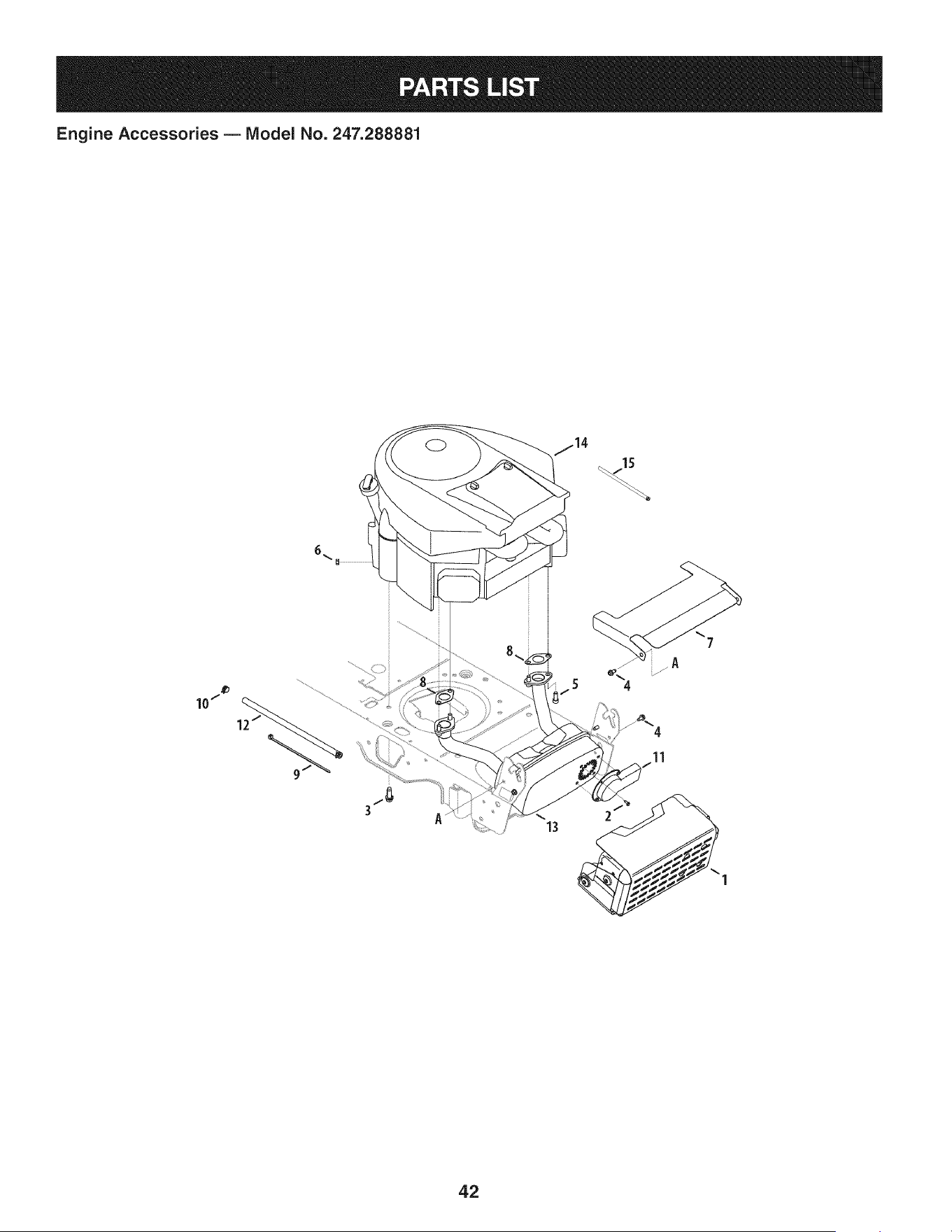
Engine Accessories B IViodel No. 247.288881
10/
6_
4
11
1
42

Engine Accessories B IViodel No. 247.288881
683-04549-0637 MulfflerShieldAssembly
2 710-0227 Screw,IndentedWasher,#8-18:0.500
3 710-04683 TaptiteScrew,indentedWasher,3/8-16:1.000
4 710-0599 TaptiteScrew,indentedWasher,1/4-20:0.500
5 710-1314A SocketHeadScrew,5/16-18:.750
6 712-0271 SeresNut, 1/4-20
7 783-06378A HeatShield
8 721-0460 ExhaustGasket
9 725-0157 CableTie, 3/16 X .05X 7.4
10 726-0205 HoseClamp,.490DIA.
11 751-11053 LongMufflerDeflector
12 751-10349 FuelHose
13 751-10542A Muffler
14 44P777-2799-G1/(_5ReplacementEngine
15 751-12089-28 Vent Hose,3/16 Red
43
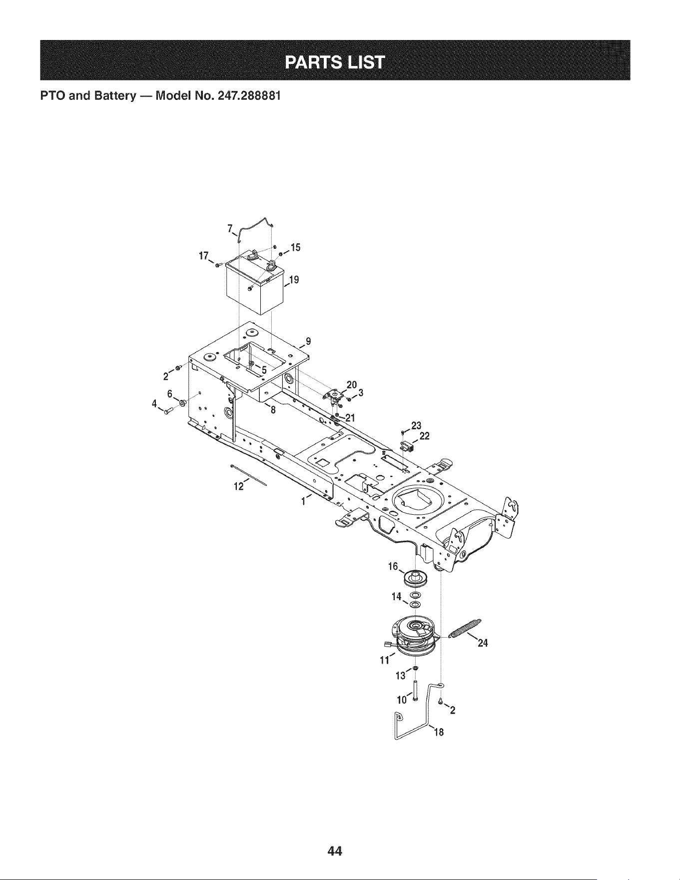
PTO and Battery B IViodel No. 247.288881
17 _o =o_115i 19
i
12
20
13
13/_
44

PTO and Battery B IViodel No. 247.288881
683-04469B-0691
2 710-04484
3 710-0653
4 710-3005
5 712-04065
6 738-04058
7 747-04121A
8 783-0349-0637
9 783-06089-0637
10 710-04379A
11 91_04552
12 725-0157
13 936-0171
14 736-0277
15 712-0271
16 756-0978B
17 710-04666
18 747-05171
19 725-05088
20 725-04439
21 712-04064
22 725-04363
23 738-04237A
24 732-0814
NS 925-04093
Frame
TaptiteScrew,indentedWasher,5/16-18:.750
TaptiteScrew,indentedWasher,1/4-20:0.375
HexHeadScrew,3/8-16:1.25
FlangelockNut,3/8-16
ShoulderSpacer,.38X 1.0X .70
BatteryHolderRod
BatteryTray
SeatFrameBracket
HexHeadScrew,7/16-20:3.50
ElectricPTOClutch
CableTie, 3/16x .05 x 7.4
LockWasher,7/16
FiatWasher,1.031x 1.620x .095
SeresNut, 1/4-20
ElectricPTOEnginePulley
HexHeadFlange,1/4-20:.75
BeltGuard
Battery
Solenoid,12V
FlangelockNut, 1/4-20
interlockSwitch
ShoulderScrew,#10-32:.500
ExtensionSpring,.56 Od.x 5.52 Lg.
Wire HarnessAssembly
45
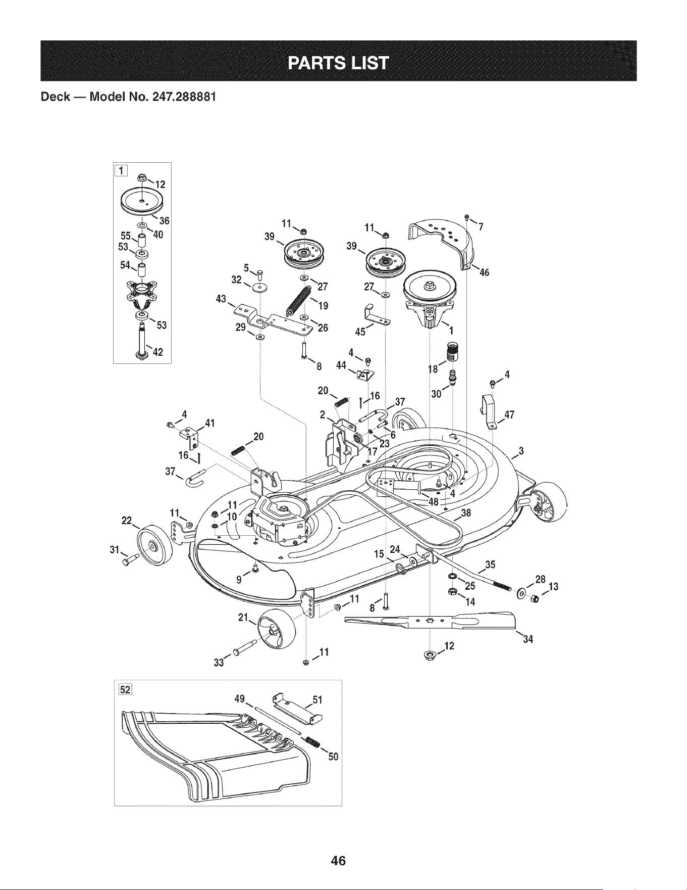
Deck B IViodel No. 247.288881
22
11
46

Deck B Model No. 247.288881
918-04636A SpindleAssembly
2 683-0254B-4028 DeckHangerBracketAssembly
3 983-04468A-4028DeckAssembly
4 710-04484 TaptiteScrew,indentedWasher,5/16-18:.750
5 710-0514 Hex HeadScrew,3/8-16:1.00
6 710-0528 Hex HeadScrew,5/16-18:1.25
7 710-0599 TaptiteScrew,indentedWasher,1/4-20:0.500
8 710-3144 Hex HeadScrew,3/8-16:2.00
9 710-3178 CarriageBolt,3/8-16:0.75
10 712-0229 PushNut,3/8
11 712-04065 FlangelockNut,3/8-16
12 712-0417A FlangeNut,5/8-18
13 712-04243 LockNut, 1/2-13
14 912-0641 HexNut,M16-1.5DIN936
15 753-04070 LynchPin,.1875
16 914-0470 CotterPin, 1/8X 1.25
17 917-04074 DeckGear
18 921-04041 WaterNozzleAdaptor
19 732-0459C ExtensionSpring,.94DIA.X 6.74LG
20 732-04652 CompressionSpring,.535ODX 1.751LG
21 734-04155 FrontDeckWheel
22 734-0973 RearDeckWheel
23 936-0119 LockWasher,5/16
24 936-0179 FiatWasher,.531X 1.25X .100
25 736-0225 LockWasher,5/8
26 736-0258 FiatWasher,.385X 1.0X .135
27 736-0262 FiatWasher,.385X .870X .092
28 736-0317 BellWasher,.63X 1.25X .18
936-0344 FiatWasher,.385X 1.0X .030
30 737-04003D WaterNozzle
31 938-0373 ShoulderBolt,.496X 1.525:3/8-16
i32 738-04162A ShoulderSpacer,.8840X .190
i33 938-3056 ShoulderBolt, .496X 2.50:3/8-16
i34 942-04290 2-in-1CuttingBlade
i35 747-04944B DeckLiftRod
i36 756-04356 DeckPulley,6.93DIA
i37 747-1116 DeckReleaseHandleRod
i38 954-04219 V-Belt
i39 756-04129B IdlerPulley,4.25"DIA
i40 936-0351 FlatWasher,.760IDX1.50OD
i41 783-04740-0637 DeckEngageCableBracket
42 738-1186A SpindleShaft,6.05 LG.
43 783-05946 IdlerBracket
i44 783-06243-0637 DeckEngageCableBracket
i45 783-06368A-06374.25 PulleyBeltGuardBracket
i46 731-06496 BeltCover
i47 783-06632-4028 DeckStop
i48 783-06643-4028 DeckIdlerSupportBracket
i49 711-04847B HingePin
i50 732-04372 TorsionSpring
i51 783-06074A ChuteBracket
i52 631-04460 ChuteDeflector
i53 941-0919 BallBearing,.7871DX 1.850DX.551
i54 750-04936 Spacer,.792X 1.060X 1.860LG
i55 750-0952 Spacer,.792X 1.060X 1.800LG
47
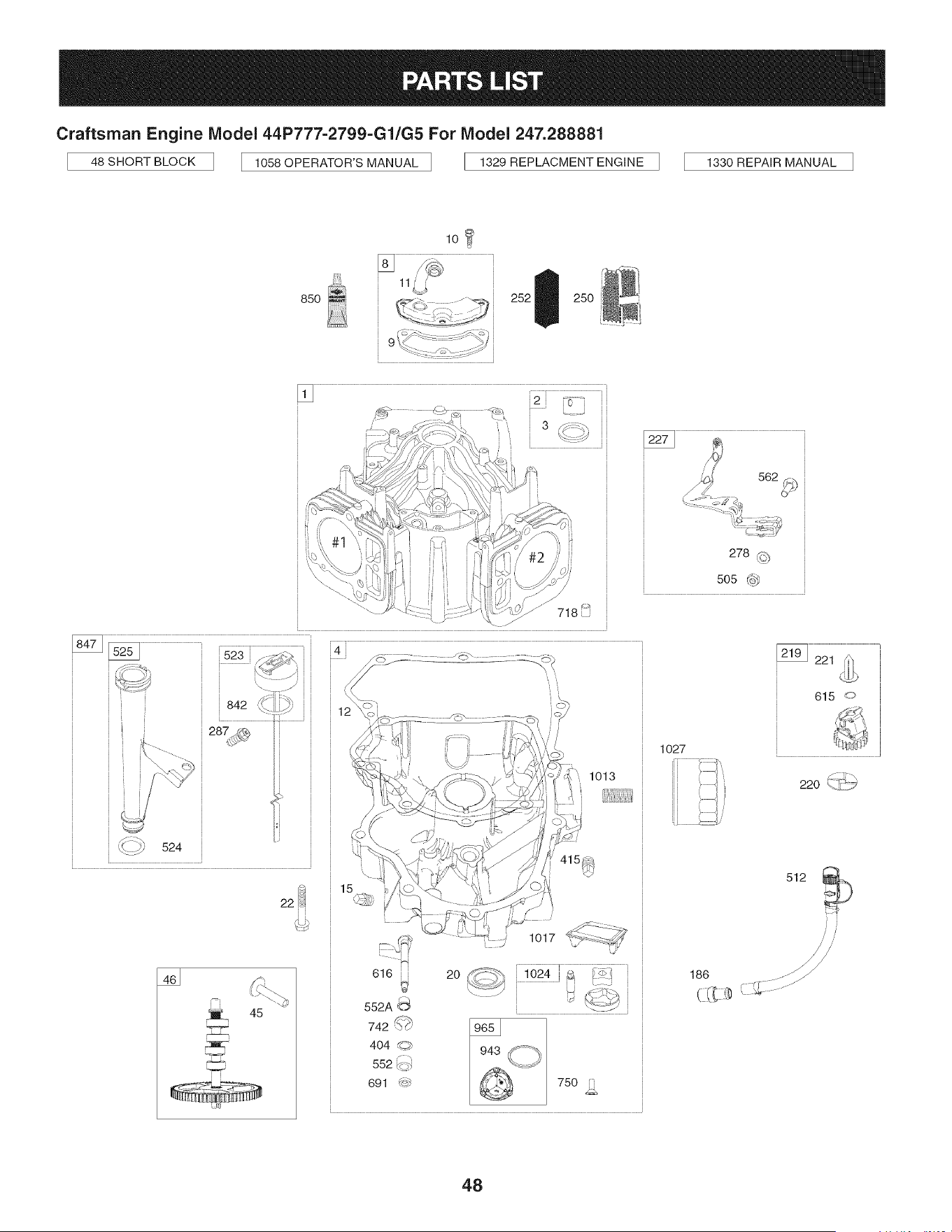
Craftsman Engine Model 44P777-2799-Gl/G5For Model 247.288881
48 SHORT BLOCK 1058 OPERATOR'S MANUAL 1329 REPLACMENT ENGINE 1330 REPAIR MANUAL
lOl
850
9
u
252 250
i i i i ii
1013
45
616
552A_
742_{_}}
404 :_
552_
691 _}
L
2O
1017
750 1i
615 ,o
1027
512
188 _ ............//
48
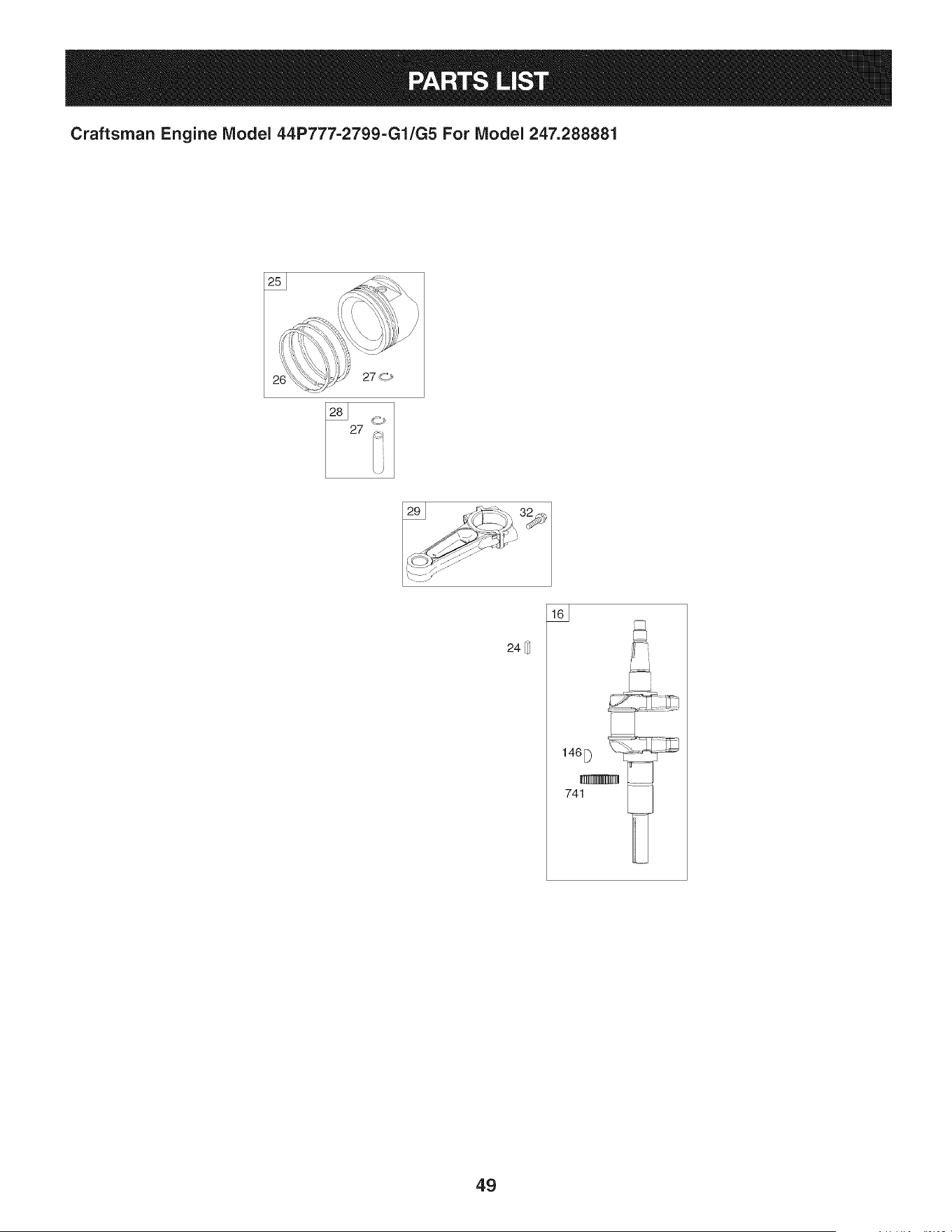
Craftsman Engine IViodel 44P777-2799-G1/G5 For IViodel 247.288881
_'_ ..... I
24[_
163
741
49
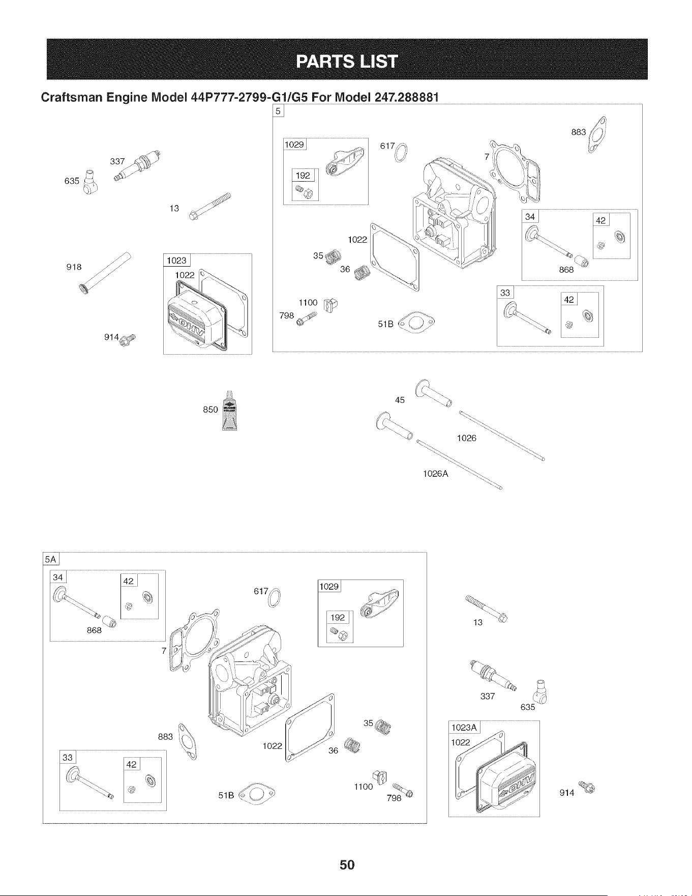
Craftsman Engine IViodel 44P777=2799=Gl/G5 For IVlodel 247.288881
883
13
635
1o22
36 _
1100
850
883
1o22
337
1022 _" '
914 _
50
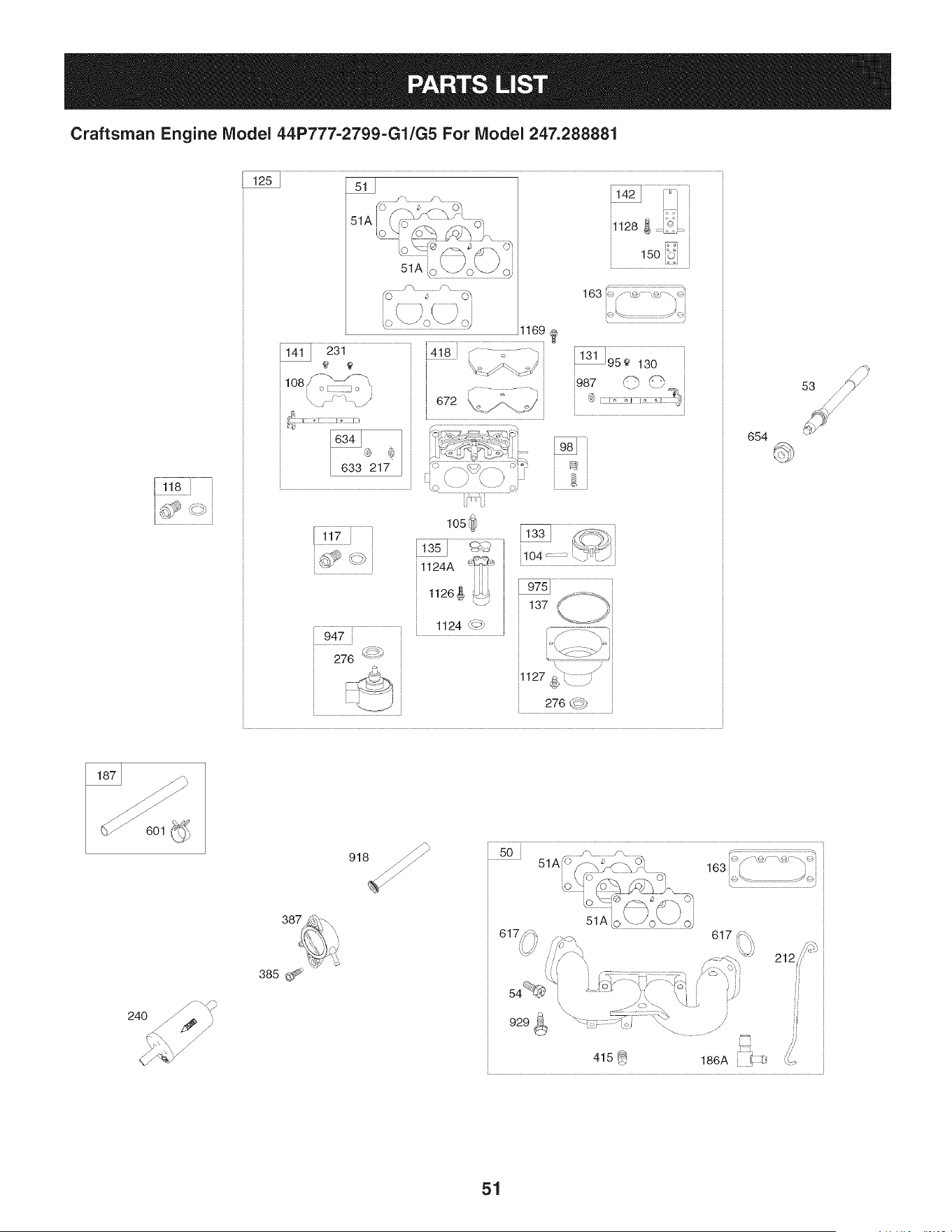
Craftsman Engine IViodel 44P777=2799=G1/G5 For IViodel 247.288881
51A
i
51A
108' _,, '_ i i . i
[ 633 217
150 iOi
183 ic,'/'-s{J "_s_"'_"i
i i i i
J
[illllillii ili,
i¼_i i L
i 276 _f i
654
24O
387
51
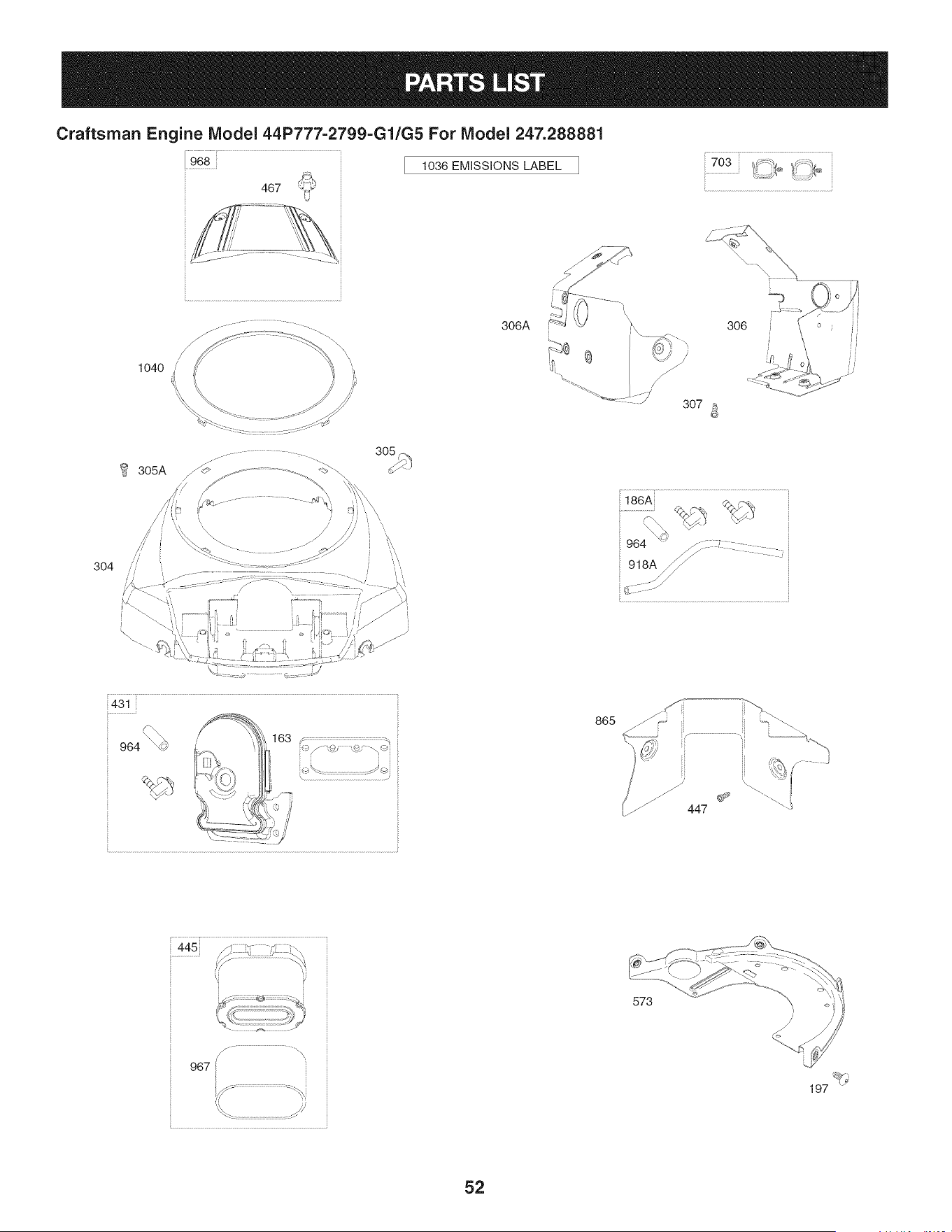
Craftsman Engine Model 44P777-2799=Gl/G5 For Model 247.288881
1036 EMiSSiONS LABEL
703 t_ _* _(j _:,_,
1040
...........................................................................................................................................i
306A K 306
_" 307 a
@
3O4
_186A %¢-%
964 '1¢ /-::::- : .........
865
z!'
447
ii
445 ::::::::::::::::::::::::::
......................(_ ...........................................m_
/. .............................................\
967 ii
573
52
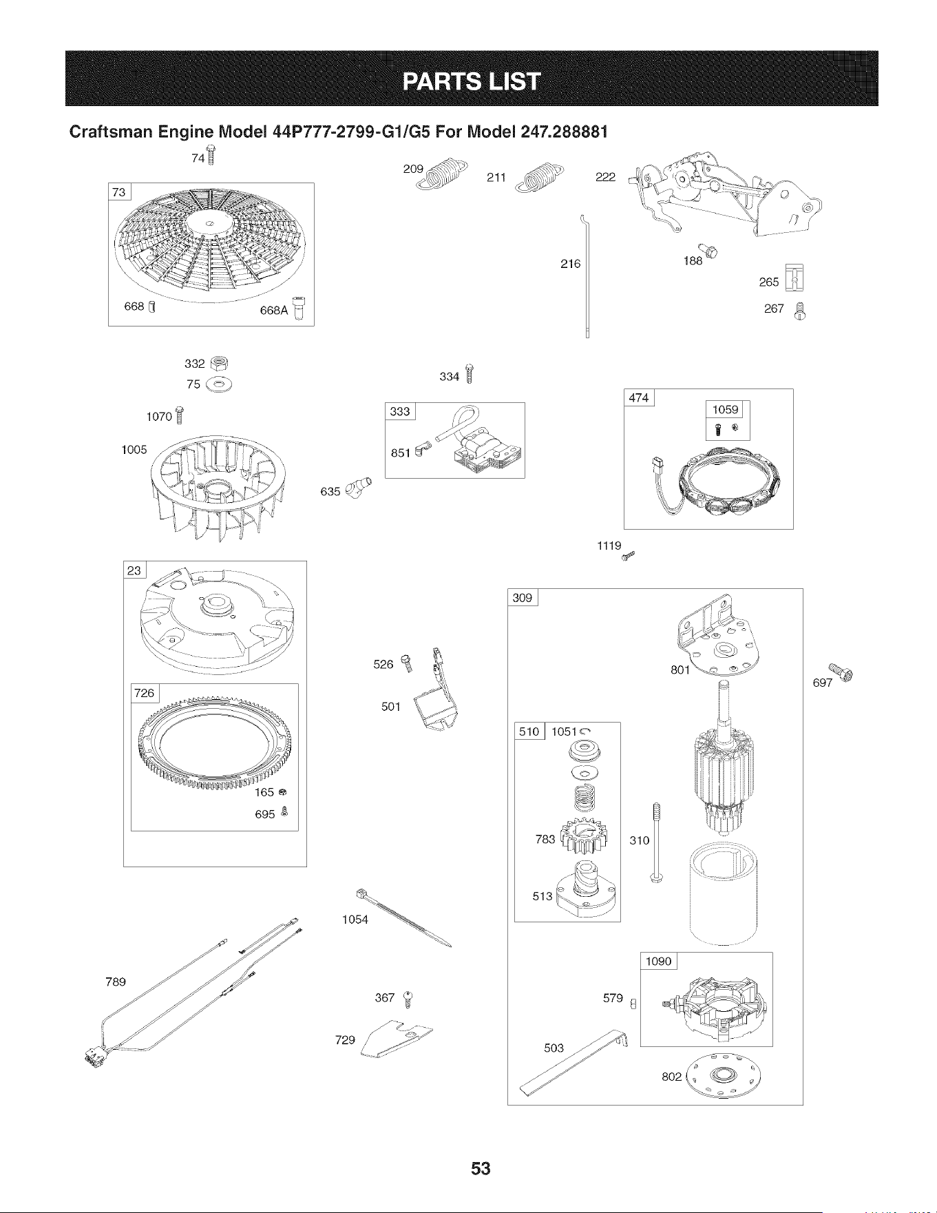
Craftsman Engine IViodel 44P777=2799=G1/G5 For IViodel 247.288881
72_
211_ 222
216
1070
1005
334
1119
695
789
526
501
367
729 _ .._i
801
1051 o
783
513
53
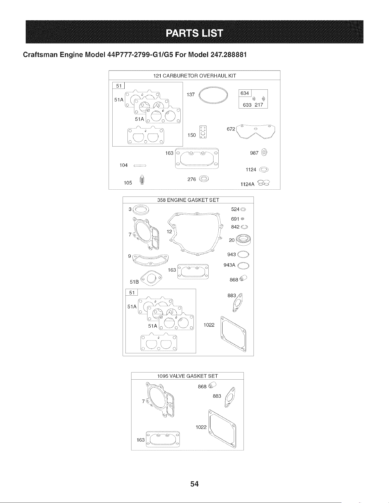
Craftsman Engine Model 44P777-2799-Gl/G5 For Model 247.288881
51A
121 CARBURETOR OVERHAUL KIT
........../ ..................s\
51A
137
15O
672
633 217
163 987@
lO4 ,:::
105
1124 d::":_)
276_4_!i_
1124A _/
358 ENGINE GASKET SET
7
163
51B
51A
524<_
691 ®
842 _\_
20
943<//_:)
94_A<_:p
868_ )
1022
1095 VALVE GASKET SET
868_ )
883
1o22
/1
54

Craftsman Engine IViodel 44P777=2799=Gl/G5 For IViodel 247.288881
|= e e
793564 CylinderAssembly 699816
2 499585 Kit-Bushing/Seal(MagnetoSide) 494439
3 391086s Seal-Oil (MagnetoSide) 698425
4 796307 Sump-Engine 691056
5 799088 Head-Cylinder(Cylinder#1) 690718
5A 799089 Head-Cylinder(Cylinder#2) 98 699721
7 693997 Gasket-CylinderHead 104 694918
8 792185 BreatherAssembly 105 797410
9 690937 Gasket-Breather 108 699723
10 697551 Screw(BreatherAssembly) 117 842585
11 792184 Tube-Breather
12 697227 Gasket-Crankcase
13 793988 Screw(Cylinder Head)
15 690946 Plug-OilDrain
16 796540 Crankshaft
20 795387 Seal-Oil (PTOSide)
22 694966 Screw(CrankcaseCover/Sump)
23 691053 Flywheel
24 222698s Key-Flywheel
25 793560 PistonAssembly(Standard)
793563 PistonAssembly(.020"Oversize)
26 793561 RingSet (Standard)
792073 RingSet(.020" Oversize)
27 690975 Lock-PistonPin
28 696581 Pin-Piston
29 796209 Rod-Connecting
32 690976 Screw(ConnectingRod)
33 793357 Valve-Exhaust
34 793556 Valve-Intake
35 690963 Spring-Valve(Intake)
36 690963 Spring-Valve(Exhaust)
42 499586 Keeper-Valve
45 690977 Tappet-Valve
46 796853 Gear-Cam
48 797093 Short Block
50 695241 Manifold-Intake
51 795123 Gasket-Intake
51A 690950 Gasket-Intake
51B 690949 Gasket-Intake
53 690951 Stud (Carburetor)
D = 0 0
Screw(IntakeManifold)
73 Screen-Rotating
74 Screw(RotatingScreen)
75 Washer(Flywheel)
95 Screw(ThrottleValve)
Kit-IdleSpeed
Pin-FloatHinge
Valve-FloatNeedle
Valve-Choke
Jet-Main(Standard)(Left and RightJet)
118 791502 Jet-Main(HighAltitude)(LeftandRightJet)
121 792455 Kit-CarburetorOverhaul
125 796997 Carburetor
130 690993 Valve-Throttle
131 499805 Kit-ThrottleShaft
133 699724 Float-Carburetor
135 699729 Tube-FuelTransfer
137 690994 Gasket-FloatBowl
141 796228 Kit-ChokeShaft
142 699726 Nozzle-Carburetor
146 690979 Key-Timing
150 690995 Gasket-Nozzle
163 691001 Gasket-AirCleaner
165 693148 Nut (RingGear)
186 796532 Connector-Hose(Oil DrainHose)
186A 799158 Connector-Hose(EVAPSystem)
186B 795985 Connector-Hose(IntakeManifold)
187 791766 Line-Fuel(Cut to RequiredLength)
188 697551 Screw(ControlBracket)
192 690083 Adjuster-RockerArm
197 697820 Screw(Back Plate)
209 798921 Spring-Governor(Orange)
211 691019 Spring-GovernedIdle (No Color)
212 695238 Link-Throttle
216 796229 Link-Choke
217 695409 Spring-ChokeReturn
219 793338 Gear-Governor
220 690412 Washer(GovernorGear)
221 841026 Cup-Governor
222 798915 Bracket-Control
55

Craftsman Engine IViodel 44P777=2799=Gl/G5 For IViodel 247.288881
D" 0 0
798856 Lever-GovernorControl 691036
231 690718 Screw(ChokeValve) 691032
240 695666 Filter-Fuel 691037
250 690957 Retainer-Breather 697551
252 794389 Collector-Oil 796638
265 691024 Clamp-Casing 690553
267 695134 Screw(CasingClamp) 562 690311
276 695410 Washer-Sealing 573 790444
278 792651 Washer(GovernorControlLever) 579 691029
287 697551 Screw(DipstickTube) 601 691038
304 797407 Housing-Blower 615 698290
305 691005 Screw(BlowerHousing) 616 691045
305A 790690 Screw (BlowerHousingto IntakeElbow) 617 697891
306 798855 Shield-Cylinder(Cylinder#2) 633 699813
306A 796852 Shield-Cylinder(Cylinder#1) 634 698779
307 697551 Screw(CylinderShield) 635 66538s
309 795121 Motor-Starter 654 690958
310 691263 Screw(Starter Motor) 668 691215
332 691059 Nut(Flywheel) 668A 691500
333 691060 Armature-Magneto 672 690234
334 691061 Screw(MagnetoArmature) 691 790574
337 491055s Plug-Spark
358 694012 GasketSet-Engine
367 697820 Screw(WireClip)
385 797409 Screw(Fuel Pump)
387 808656 Pump-Fuel
404 690442 Washer(GovernorCrank)
415 794903 Plug(Oil PressureSwitch Hole)
418 795912 Plate-Carburetor
431 798860 Elbow-Intake
445 792105 Filter-AirCleanerCartridge
447 691003 Screw(Air GuideCover)
467 790697 Knob-AirCleaner
474 696458 Alternator
501 797375 Regulator
503 691532 Strap-Starter
505 691029 Nut(GovernorControlLever)
510 794360 Drive-Starter
512 796530 Hose-OilDrain
513 692024 Clutch-Drive
D = 0 O
Dipstick
524 Seal-DipstickTube
525 Tube-Dipstick
526 Screw(Regulator)
552 Bushing-GovernorCrank
552A Bushing-GovernorCrank
Screw(GovernorControl Lever)
Plate-Back
Nut (StarterCable)
Clamp-Hose(Black)
Retainer-GovernorShaft
Crank-Governor
Seal-O Ring(IntakeManifold)(Red)
Seal-Choke/ThrottleShaft(Choke Shaft)
Spring/SealAssembly
Boot-SparkPlug
Nut (Carburetor)
Spacer(RotatingScreen)
Spacer(RotatingScreen)
Gasket-CarburetorPlate
Seal-GovernorShaft
695 693149 Screw(Ring Gear)
697 690372 Screw(DriveCap)
703 691010 Clip
718 690959 Pin-Locating
726 499612 Gear-Ring
729 797454 Clip-Wire
741 690980 Gear-Timing
742 690328 Retainer-ERing(GovernorCrank)
750 796208 Screw(Oil PumpCover)
783 695708 Gear-Pinion
789 797424 Harness-Wiring
798 697890 Screw(RockerArm)
801 691283 Cap-Drive
802 691286 Cap-End
842 691031 Seal-ORing(DipstickTube)
847 499602 Dipstick/TubeAssembly
850 100106 Sealant-Liquid
851 493880s Terminal-SparkPlug
865 792286 Cover-AirGuide(Valley)
56

Craftsman Engine IViodel 44P777=2799=Gl/G5 For IViodel 247.288881
690968 Seal-Valve
883 690970 Gasket-Exhaust
914 691127 Screw(Rocker Cover)
918 797408 Hose-Vacuum(RockerCover)
918A 799160 Hose-Vacuum(EVAPSystem)
929 695239 Screw(ChokeControl Bracket)
943 796222 Seal-O Ring (Oil PumpCover)
947 798779 Solenoid-Fuel
964 799159 Cap-Connector
965 796221 Cover-OilPump
967 792303 Filter-PreCleaner
968 795120 Cover-AirCleaner
975 798778 Bowl-Float
987 691000 Seal-ThrottleShaft
1005 791236 Fan-Flywheel
1013 690954 Nipple-OilFilter
1017 796214 Screen-Oil Pump
1022 690971 Gasket-RockerCover
1023 793146 Cover-Rocker(Cylinder#1)
1023A 499600 Cover-Rocker(Cylinder#2)
1024 796220 Pump-Oil
1026 690981 Rod-Push(Exhaust)(Steel)
1026A 690982 Rod-Push(Intake)(Aluminum)
1027 795890 Filter-Oil
1029 690972 Arm-Rocker
Label-Emissions(Availablefrom a Briggs
1036
& StrattonAuthorizedDealer)
1040 791237 Plate-Trim
1051 691265 Ring-Retaining(StarterDrive)
1054 280275 Tie-Cable
1058 278776TRI Operator'sManual
1059 698516 Kit-Screw/Washer(Alternator)
1070 791680 Screw(FlywheelFan)
1090 691293 Retainer-Brush
1095 694013 GasketSet-Valve
1100 791959 Pivot-RockerArm
1119 691183 Screw(Alternator)
1124 841653 Seal-O Ring (FuelTransferTube)
1124A 690988 Seal-ORing (FuelTransferTube)
1126 690991 Screw(FuelTransferTube)
D = 0 O
695407 Screw(FuelBowl)
1128 690990 Screw(CarburetorNozzle)
1169 690990 Screw(CarburetorPlate)
44P777-
1329 2799-G1/G5 ReplacementEngine
1330 273521 RepairManual
Key No. 358 EngineGasketSet
Key No. 1095 ValveGasketSet
Key No. 121 CarburetorOverhaulKit
57
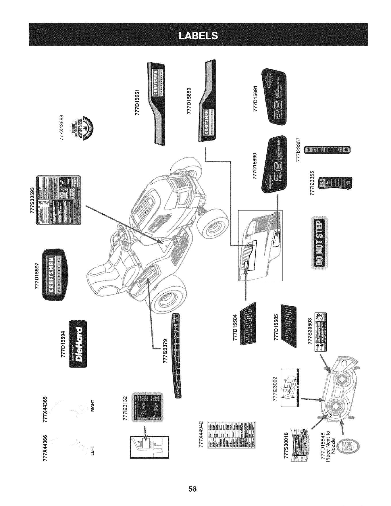
777S33593
777D15597
O'1
777X44366
LEFT
777X44942
777S30018
777D15546
777X44365
RIGHT
777J23132
777D15594
777123092
777J23379
777D15584
777D15585
777S30503
777D15690
777123357
777123355
777X43688
B0._
USEE8_ORFUEL
C8_MM6 MO_
mAN1_, ETHANOL
777D15651
777D15650
777D15691
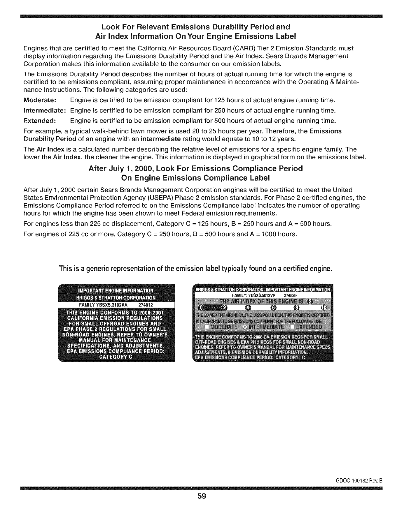
Look For Relevant Emissions Durability Period and
Air index information On Your Engine Emissions Label
Engines that are certified to meet the California Air Resources Board (CARB) Tier 2 Emission Standards must
display information regarding the Emissions Durability Period and the Air Index. Sears Brands Management
Corporation makes this information available to the consumer on our emission labels.
The Emissions Durability Period describes the number of hours of actual running time for which the engine is
certified to be emissions compliant, assuming proper maintenance in accordance with the Operating & Mainte-
nance Instructions. The following categories are used:
Moderate: Engine is certified to be emission compliant for 125 hours of actual engine running time.
Intermediate: Engine is certified to be emission compliant for 250 hours of actual engine running time.
Extended: Engine is certified to be emission compliant for 500 hours of actual engine running time.
For example, a typical walk-behind lawn mower is used 20 to 25 hours per year. Therefore, the Emissions
Durability Period of an engine with an intermediate rating would equate to 10 to 12 years.
The Air index is a calculated number describing the relative level of emissions for a specific engine family. The
lower the Air Index, the cleaner the engine. This information is displayed in graphical form on the emissions label.
After July 1,2000, Look For Emissions Compliance Period
On Engine Emissions Compliance Label
After July 1, 2000 certain Sears Brands Management Corporation engines will be certified to meet the United
States Environmental Protection Agency (USEPA) Phase 2 emission standards. For Phase 2 certified engines, the
Emissions Compliance Period referred to on the Emissions Compliance label indicates the number of operating
hours for which the engine has been shown to meet Federal emission requirements.
For engines less than 225 cc displacement, Category C = 125 hours, B = 250 hours and A = 500 hours.
For engines of 225 cc or more, Category C = 250 hours, B = 500 hours and A = 1000 hours.
This is a generic representation of the emission label typically found on a certified engine.
FAMILYYSSXS.3192VA 274812
GDOC-100182Rev.B
59
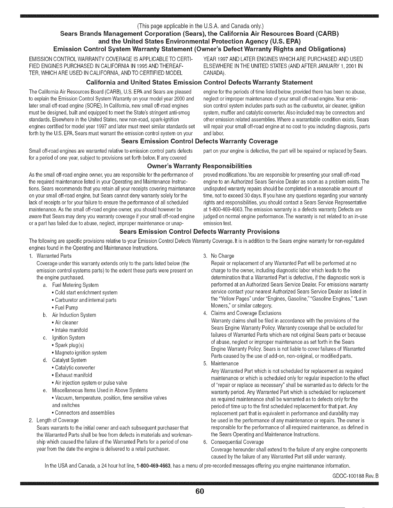
(Thispageapplicableinthe U.S.A.and Canadaonly.)
Sears Brands Management Corporation (Sears), the California Air Resources Board (CARD)
and the United States Environmental Protection Agency (U.S. EPA)
Emission Control System Warranty Statement (Owner's Defect Warranty Rights and Obligations)
EMISSIONCONTROLWARRANTYCOVERAGEISAPPLICABLETO CERTI-
FIEDENGINESPURCHASEDIN CALIFORNIAIN 1995ANDTHEREAF-
TER,WHICHARE USED INCALIFORNIA,ANDTO CERTIFIEDMODEL
California and United States Emission
The CaliforniaAir ResourcesBoard(CARD),U.S.EPAand Searsare pleased
to explainthe EmissionControlSystemWarrantyon your modelyear2000and
latersmalloff-roadengine(SORE).In California,newsmall off-roadengines
mustbe designed,builtand equippedto meettheState'sstringentanti-smog
standards.Elsewherein theUnitedStates, newnon-road,spark-ignition
enginescertifiedfor modelyear 1997and latermustmeetsimilarstandardsset
forth bythe U.S.EPA.Sears mustwarrantthe emissioncontrol systemonyour
YEAR 1997AND LATERENGINESWHICHARE PURCHASEDAND USED
ELSEWHEREIN THE UNITEDSTATES(ANDAFTERJANUARY1,2001 IN
CANADA).
Control Defects Warranty Statement
enginefor theperiodsoftime listedbelow,providedtherehas been noabuse,
neglector impropermaintenanceof your smalloff-roadengine.Youremis-
sion controlsystemincludespartssuch as thecarburetor,air cleaner,ignition
system,mufflerand catalyticconverter.Also includedmaybe connectorsand
otheremissionrelatedassemblies.Wherea warrantableconditionexists,Sears
will repairyour smalloff-roadengineat no costto you includingdiagnosis,parts
and labor.
Sears Emission Control Defects Warranty Coverage
Smalloff-roadenginesarewarrantedrelativeto emissioncontrol partsdefects
fora periodof one year,subjectto provisionsset forth below.Ifany covered
Owner's Warranty
Asthe smalloff-roadengine owner,you are responsiblefor the performanceof
therequiredmaintenancelistedin yourOperatingand MaintenanceInstruc-
tions.Searsrecommendsthatyou retain all yourreceiptscoveringmaintenance
on yoursmalloff-roadengine,butSears cannotdenywarrantysolelyfor the
lackof receiptsorfor yourfailureto ensurethe performanceof all scheduled
maintenance.As the smalloff-roadengineowner,you shouldhoweverbe
awarethat Searsmaydenyyou warrantycoverageif your smalloff-roadengine
ora part hasfailed dueto abuse,neglect,impropermaintenanceor unap-
parton yourengineis defective,the part willbe repairedorreplacedbySears.
Responsibilities
provedmodifications.Youare responsiblefor presentingyour smalloff-road
engineto an AuthorizedSearsServiceDealeras soonas a problemexists.The
undisputedwarrantyrepairsshouldbe completedin a reasonableamountof
time,notto exceed30 days. Ifyou haveany questionsregardingyourwarranty
rightsand responsibilities,you shouldcontacta SearsService Representative
at 1-800-469-4663.The emissionwarrantyis a defectswarranty.Defectsare
judgedon normalengineperformance.Thewarrantyis not relatedto an in-use
emissiontest.
Sears Emission Control Defects Warranty Provisions
ThefollowingarespecificprovisionsrelativetoyourEmissionControlDefectsWarrantyCoverage.ItisinadditiontotheSearsenginewarrantyfornon-regulated
enginesfound in the Operatingand MaintenanceInstructions.
1. WarrantedParts
Coverageunderthis warrantyextendsonly to the parts listedbelow (the
emissioncontrolsystemsparts)to the extentthese partswere presenton
the engine purchased.
a. FuelMeteringSystem
• Cold start enrichmentsystem
• Carburetorand internalparts
• FuelPump
b. Air lnduction System
• Air cleaner
• Intakemanifold
c. IgnitionSystem
• Spark plug(s)
• Magnetoignitionsystem
d. CatalystSystem
• Catalyticconverter
• Exhaustmanifold
• Air injectionsystemor pulsevalve
e. MiscellaneousItemsUsedin AboveSystems
• Vacuum,temperature,position,timesensitivevalves
andswitches
• Connectorsandassemblies
2. Lengthof Coverage
Searswarrantsto the initialownerand eachsubsequentpurchaserthat
the WarrantedParts shallbe free from defects in materialsandworkman-
shipwhich causedthefailure of the WarrantedPartsfor a periodof one
yearfrom the datethe engineis deliveredto a retailpurchaser.
3. NoCharge
Repairor replacementof anyWarrantedPartwill be performedat no
chargeto the owner,includingdiagnosticlabor whichleadsto the
determinationthata WarrantedPartis defective,if the diagnosticworkis
performedat an AuthorizedSearsServiceDealer.Foremissionswarranty
servicecontact yournearestAuthorizedSearsServiceDealeras listed in
the "YellowPages"under"Engines,Gasoline,""GasolineEngines,""Lawn
Mowers,"or similar category.
4. Claimsand CoverageExclusions
Warrantyclaimsshall be filed in accordancewiththe provisionsof the
Sears EngineWarrantyPolicy.Warrantycoverageshall be excludedfor
failuresof WarrantedPartswhichare not original Sears partsor because
of abuse, neglector impropermaintenanceas setforth inthe Sears
EngineWarrantyPolicy.Sears is notliableto coverfailuresof Warranted
Partscausedby theuse of add-on,non-original,or modifiedparts.
5. Maintenance
Any WarrantedPart whichis notscheduledfor replacementas required
maintenanceor whichis scheduledonly for regularinspectionto the effect
of "repairor replaceas necessary"shallbe warrantedasto defectsfor the
warrantyperiod.Any WarrantedPartwhich is scheduledfor replacement
as requiredmaintenanceshallbe warrantedasto defectsonly forthe
periodof time upto the firstscheduledreplacementfor that part. Any
replacementpart that is equivalentin performanceand durabilitymay
be usedin the performanceof any maintenanceor repairs.The owneris
responsibleforthe performanceof all requiredmaintenance,as definedin
the SearsOperatingand MaintenanceInstructions.
6. ConsequentialCoverage
Coveragehereundershallextendto the failure of any engine components
caused bythe failureof any WarrantedPartstill underwarranty.
Inthe USAandCanada,a 24 hour hotline, 1-800-469-4663,has a menuof pre-recordedmessagesofferingyou enginemaintenanceinformation.
GD0C-100188Rev.B
60
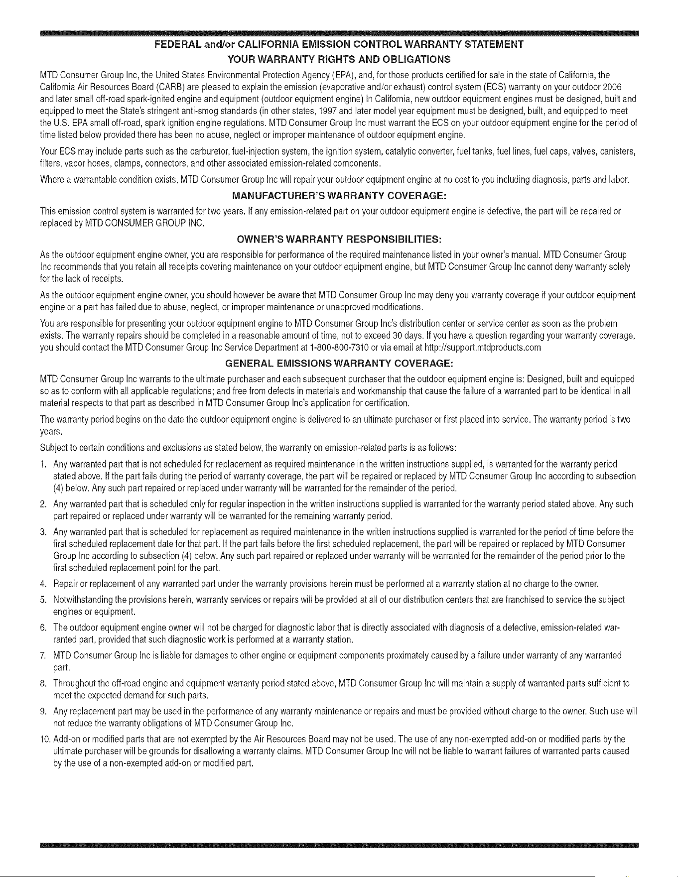
FEDERAL and/or CALIFORNIA EMISSION CONTROL WARRANTY STATEMENT
YOUR WARRANTY RIGHTS AND OBLIGATIONS
MTDConsumerGroupInc,the UnitedStatesEnvironmentalProtectionAgency (EPA),and, forthose productscertifiedfor sale in the stateof California,the
CaliforniaAir ResourcesBoard(CARB)are pleasedto explainthe emission(evaporativeand/or exhaust)controlsystem(ECS) warrantyon youroutdoor 2006
andlater smalloff-roadspark-ignitedengine andequipment(outdoorequipmentengine)In California,new outdoorequipmentengines mustbe designed,built and
equippedto meetthe State'sstringentanti-smog standards(in otherstates, 1997andlater modelyear equipmentmustbe designed,built, and equippedto meet
theU.S. EPAsmalloff-road, sparkignitionengine regulations.MTDConsumerGroupInc mustwarrantthe ECSon your outdoorequipmentenginefor the periodof
timelisted belowprovidedtherehas been no abuse,neglector impropermaintenanceof outdoor equipmentengine.
Your ECSmayincludeparts such as thecarburetor,fuel-injectionsystem,the ignitionsystem,catalyticconverter,fuel tanks,fuel lines,fuel caps,valves,canisters,
filters,vaporhoses,clamps,connectors,andotherassociatedemission-relatedcomponents.
Wherea warrantableconditionexists, MTDConsumerGroupIncwill repairyouroutdoorequipmentengineat no cost to you includingdiagnosis,parts and labor.
MAN UFACTURER'S WARRANTY COVERAGE:
Thisemissioncontrolsystemis warrantedfor two years. If any emission-relatedpart on your outdoorequipmentengineis defective,the part will berepairedor
replacedby MTDCONSUMERGROUPINC.
OWNER'S WARRANTY RESPONSIBILITIES:
Asthe outdoorequipmentengineowner,you are responsiblefor performanceof the requiredmaintenancelisted inyour owner'smanual.MTDConsumerGroup
Inc recommendsthat you retain all receiptscoveringmaintenanceon youroutdoor equipmentengine,butMTDConsumerGroupInc cannotdeny warrantysolely
forthe lackof receipts.
Asthe outdoorequipmentengineowner,you shouldhoweverbe awarethat MTDConsumerGroupInc maydenyyou warrantycoverageif your outdoorequipment
engineor a part has failed due to abuse, neglect,or impropermaintenanceor unapprovedmodifications.
Youare responsiblefor presentingyouroutdoor equipmentengineto MTDConsumerGroupInc's distributioncenterorservicecenteras soon asthe problem
exists.The warrantyrepairsshouldbe completedin a reasonableamountof time, not to exceed30 days.If you havea question regardingyour warrantycoverage,
you shouldcontactthe MTDConsumerGroupIncService Departmentat 1-800-800-7310or via email at http://support.mtdproducts.com
GENERAL EMISSIONS WARRANTY COVERAGE:
MTDConsumerGroupIncwarrantsto the ultimatepurchaserand eachsubsequentpurchaserthat theoutdoorequipmentengineis: Designed,built and equipped
so asto conformwithall applicableregulations;and freefrom defects in materialsand workmanshipthatcausethe failureof a warrantedpart to be identicalin all
materialrespectsto that part as describedin MTDConsumerGroup Inc'sapplicationfor certification.
The warrantyperiodbeginson thedate the outdoor equipmentengineis deliveredto an ultimate purchaseror first placedinto service.The warrantyperiodis two
years.
Subjectto certain conditionsand exclusionsasstated below,the warrantyon emission-relatedparts is asfollows:
1. Any warrantedpart that is not scheduledfor replacementas requiredmaintenancein thewritten instructionssupplied, is warrantedforthe warrantyperiod
statedabove. Ifthe part fails duringthe period of warrantycoverage,thepart will berepairedor replacedbyMTDConsumerGroupInc accordingto subsection
(4) below. Anysuch part repairedor replacedunderwarrantywillbe warrantedfor the remainderof the period.
2. Any warrantedpart that is scheduledonly for regularinspectionin the writteninstructionssupplied is warrantedforthe warrantyperiodstatedabove.Any such
part repairedor replacedunderwarrantywill bewarrantedforthe remainingwarrantyperiod.
3. Any warrantedpart that is scheduledfor replacementas requiredmaintenancein the written instructionssuppliedis warrantedfor the periodof time beforethe
first scheduledreplacementdatefor that part.If the partfails beforethefirst scheduledreplacement,the part will be repairedor replacedby MTDConsumer
GroupInc accordingto subsection(4) below.Any such part repairedor replacedunderwarrantywill be warrantedfor the remainderof the periodpriorto the
first scheduledreplacementpointfor the part.
4. Repairor replacementof any warrantedpart underthe warrantyprovisionshereinmustbe performedat a warrantystationat no chargeto the owner.
5. Notwithstandingthe provisionsherein,warrantyservicesor repairswill be providedat all of our distributioncentersthatare franchisedto servicethe subject
enginesor equipment.
6. The outdoorequipmentengine ownerwill not be chargedfor diagnostic laborthat is directlyassociatedwithdiagnosisof a defective,emission-relatedwar-
rantedpart, providedthat suchdiagnosticwork is performedat a warrantystation.
7. MTDConsumerGroupInc is liablefor damagesto otherengineor equipmentcomponentsproximatelycausedby a failure underwarrantyof any warranted
part.
8. Throughoutthe off-roadengineand equipmentwarrantyperiodstatedabove,MTDConsumerGroupInc will maintaina supply of warrantedparts sufficientto
meetthe expecteddemandfor such parts.
9. Any replacementpart may be usedinthe performanceof any warrantymaintenanceor repairsand mustbe providedwithoutchargeto the owner.Suchuse will
notreducethe warrantyobligationsof MTDConsumerGroupInc.
10.Add-onor modifiedpartsthat are not exemptedbythe Air ResourcesBoardmay not be used.The use of any non-exemptedadd-on or modifiedparts by the
ultimatepurchaserwill begroundsfor disallowinga warrantyclaims. MTDConsumerGroup Incwill notbe liableto warrantfailuresof warrantedparts caused
bythe useof a non-exemptedadd-onor modifiedpart.
WARRANTED PARTS:
The repairor replacementof any warrantedpart otherwiseeligiblefor warrantycoveragemaybe excludedfromsuch warrantycoverageif MTDConsumerGroup
Inc demonstratesthatthe outdoor equipmentenginehas beenabused,neglected,or improperlymaintained,and thatsuch abuse, neglect,or impropermainte-
nancewasthe direct causeof the needfor repairor replacementof the part.That notwithstanding,any adjustmentof a componentthat hasa factoryinstalled,
andproperlyoperating,adjustmentlimitingdeviceis still eligible for warrantycoverage. Further,the coverageunderthis warrantyextendsonly to partsthat were
presenton the off-roadengineand equipmentpurchased.
Thefollowing emissionwarrantypartsare covered(if applicable):
(1) FuelMeteringSystem
• Cold start enrichmentsystem(softchoke)
• Carburetorand internalparts (or fuel injectionsystem)
• Fuelpump
• Fueltank
(2) Air InductionSystem
• Air cleaner
• Intakemanifold
(3) IgnitionSystem
• Spark plug(s)
• Magneto ignitionsystem
(4) ExhaustSystem
• Catalyticconverter
• SAI (Reed valve)
(5) MiscellaneousItemsUsedin AboveSystem
• Vacuum,temperature,position,time sensitivevalvesand switches
• Connectorsandassemblies
(6) EvaporativeControl
• Fuelhose
• Fuelhoseclamps
• Tetheredfuel cap
• Carboncanister
• Vapor lines
GDOC-100223Rev.A
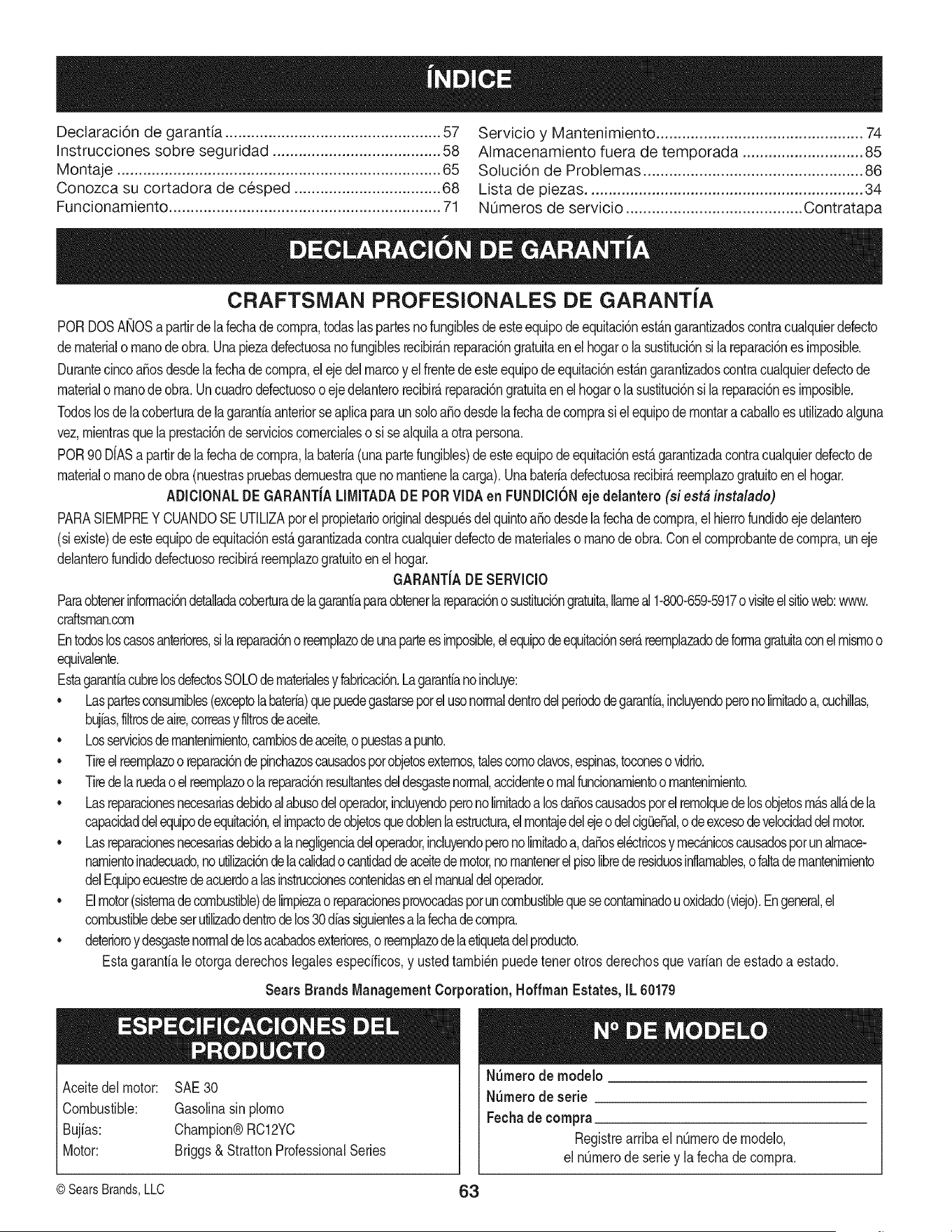
Declaracion de garantia .................................................. 57
Instrucciones sobre seguridad ....................................... 58
Montaje ........................................................................... 65
Conozca su cortadora de cesped .................................. 68
Funcionamiento ............................................................... 71
Servicio y Mantenimiento ................................................ 74
Almacenamiento fuera de temporada ............................ 85
Soluci6n de Problemas ................................................... 86
Lista de piezas ................................................................ 34
NL_merosde servicio ......................................... Contratapa
CRAFTSMAN PROFESIONALES DE GARANT{A
PORDOSAMOSapartirde la fechade compra,todaslaspartesno fungiMesdeesteequipode equitacbnestAngarantizadoscontracualquierdefecto
de materialo manodeobra.Unapiezadefectuosanofungiblesrecibir_nreparaci6ngratuitaenel hogaro la sustituci6nsi la reparaci6nesimposible.
Durantecincoa_osdesdela fechadecompra,el eje delmarcoy elfrentedeesteequipodeequitaci6nest_ngarantizadoscontracualquierdefectode
materialo manodeobra.Uncuadrodefectuosoo ejedelanterorecibir_reparaci6ngratuitaen el hogaro la sustituci6nsi la reparaci6nesimposible.
Todoslosdelacoberturade lagarantiaanteriorseaplicaparaunsoloa_o desdelafechadecomprasi el equipode montara caballoesutilizadoalguna
vez,mientrasquela prestaci6nde servicioscomercialeso si sealquilaa otrapersona.
POR90 D{ASa partirdelafechadecompra,labateria(unapartefungibles)deesteequipode equitaci6nest_garantizadacontracualquierdefectode
materialo manodeobra(nuestraspruebasdemuestraque no mantienelacarga).Unabateriadefectuosarecibir_reemplazogratuitoen el hogar.
ADICIONALDEGARANT{ALIMITADADE PORVIDAen FUNDICK)Neje delantero (si est# instalade)
PARASIEMPREY CUANDOSE UTILIZAporel propietariooriginaldespu_sdelquintoa_o desdela fechade compra,el hierrofundidoejedelantero
(siexiste)de esteequipodeequitaci6nest_garantizadacontracualquierdefectodematerialeso manodeobra.Conel comprobantede compra,uneje
delanterofundidodefectuosorecibirAreemplazogratuitoenelhogar.
GARANT{ADESERVlCIO
Paraobtenerinformaci6ndetalladacoberturadelagarantiaparaobtenerlareparaci6no sustituci6ngratuita,Ilameal1-800-659-5917ovisiteelsitioweb:www.
craftsman.com
Entodosloscasosanteriores,silareparad6no reemplazodeunaparteesimposible,elequipodeequitaci6nser_reemplazadodeformagratuitaconel mismoo
equivalente.
EstagarantiacubrelosdefectosSOLOdematerialesy fabricaci6n.Lagarantiano incluye:
• Laspartesconsumibles(exceptola bateria)quepuedegastarseporelusonormaldentrodelperiododegarantia,incluyendoperonolimitadoa,cuchillas,
bujias,filtrosdeaire,correasy filtrosdeaceite.
• Losserviciosde mantenimiento,cambiosdeaceite,o puestasapunb.
• Tireel reemplazoo reparaci6nde pinchazoscausadosporobjetosexternos,talescomoclavos,espinas,toconesovidrio.
• Tiredela ruedaoelreemplazoo lareparad6nresultantesdeldesgastenormal,accidenteo realfuncionamientoo mantenimiento.
• Lasreparacionesnecesariasdebidoalabusodeloperador,incluyendoperono limitadoa losda_oscausadosporel remolquedelosobjetosm_sall_de la
capacidaddelequipodeequitaci6n,elimpactodeobjetosquedoblenlaestructura,elmontajedelejeo delcigQe_al,odeexcesodeveiocidaddelmotor.
• Lasreparacionesnecesariasdebidoala negligenciadeloperador,incluyendoperonolimitadoa,da_osel_ctricosy mec_nicoscausadosporunalmace-
namientoinadecuado,noutilizaci6ndela calidadocantidaddeaceitedemotor,nomantenerelpisolibrederesiduosinflamables,o faltade mantenimiento
delEquipoecuestredeacuerdoalas instruccionescontenidasenelmanualdeloperador.
• Elmotor(sistemadecombustible)delimpiezao reparacionesprovocadasporuncombustiblequesecontaminadou oxidado(viejo).Engeneral,el
combustibledebeserutilizadodentrodelos30diassiguientesa lafechadecompra.
• deterioroy desgastenormaldelosacabadosexteriores,o reemplazodelaetiquetadelproducto.
Estagarantialeotorgaderechoslegalesespecificos,y ustedtambi_npuedetenerotrosderechosquevariande estadoa estado.
Sears Brands Management Cot
Aceitedel motor:
Combustible:
Bujias:
Motor:
SAE3O
Gasolinasin plomo
Champion®RC12YC
Briggs& StrattonProfessionalSeries
_oration,Hoffman Estates, IL 60179
N_mero de modelo
NSmerode serie
Fechade eompra
Registrearribael nQmerode modelo,
el n_merode seriey la fechade compra,
© SearsBrands,LLC 63
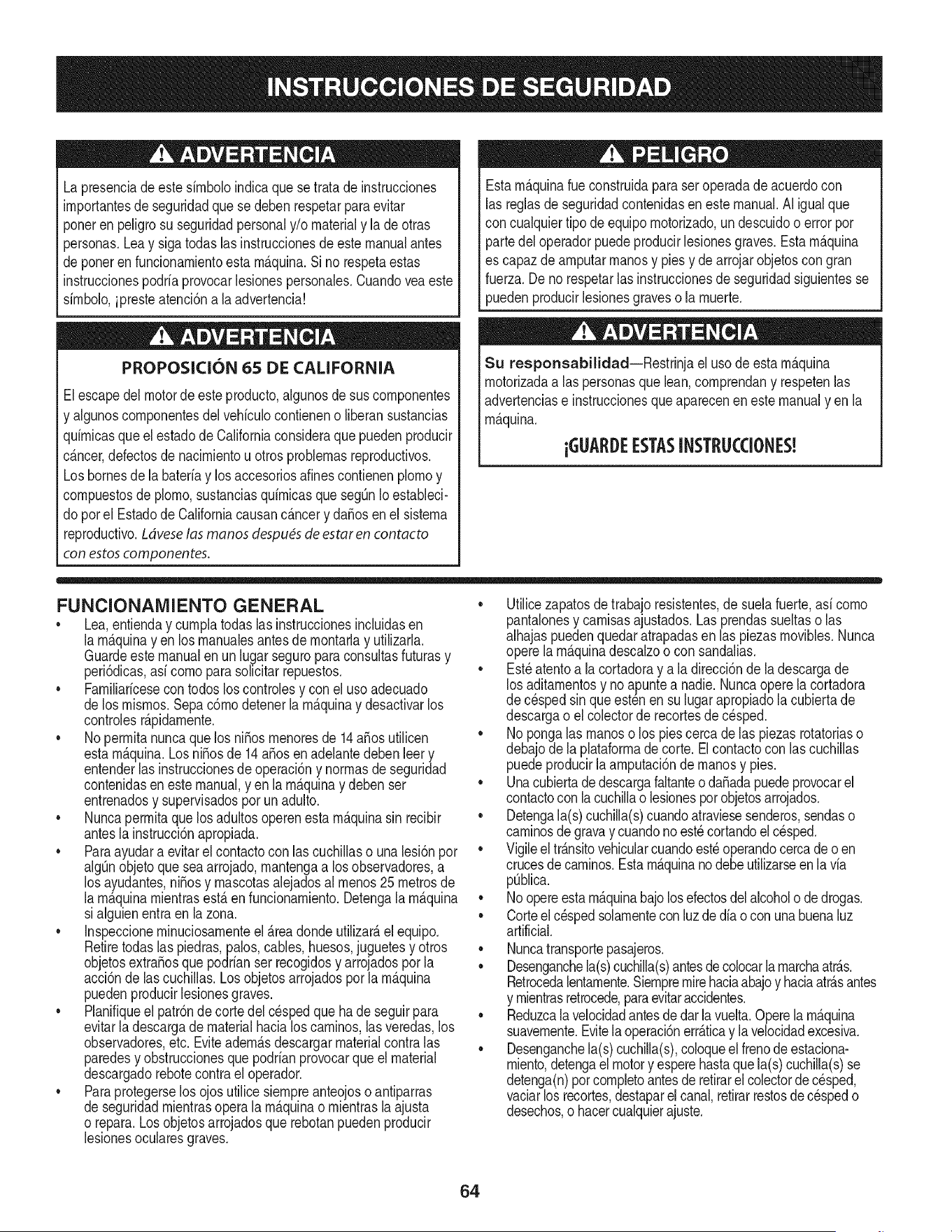
Lapresenciade este sirnboloindicaque setratade instrucciones
irnportantesde seguridadquese debenrespetarpara evitar
ponerenpeligrosu seguridadpersonaly/o materialy la de otras
personas.Leay sigatodaslasinstruccionesde este manualantes
de poneren funcionarnientoestarn_.quina.Si no respetaestas
instruccionespodriaprovocarlesionespersonales.Cuandoveaeste
sirnbolo,ipresteatenci6na la advertencia!
PROPOSICION 65 DE CALIFORNIA
Elescapedel motorde esteproducto,algunosdesuscornponentes
y algunoscornponentesdel vehiculocontieneno liberansustancias
quirnicasqueel estadode Californiaconsideraque puedenproducir
c_.ncer,defectosde nacirnientou otros problernasreproductivos.
Losbornesde la bateriay losaccesoriosdines contienenplornoy
cornpuestosde plorno,sustanciasquirnicasque segQnIoestableci-
do pot el Estadode Californiacausanc_.ncery da_osen el sisterna
reproductivo.Ldveselas manos despu_sde estaren contacto
con estoscomponentes.
Estarn_.quinarueconstruidapara seroperadadeacuerdocon
las reglasde seguridadcontenidasen este manual.AI igualque
concualquiertipo deequipornotorizado,un descuidoo errorpor
partedeloperadorpuedeproducirlesionesgraves.Estarn_.quina
es capazde arnputarrnanosy piesy de arrojarobjetoscon gran
fuerza.De norespetarlas instruccionesde seguridadsiguientesse
puedenproducirlesionesgraveso la rnuerte.
Su responsabilidad--Restrinja el usode esta rn_.quina
rnotorizadaalas personasque lean,cornprendany respetenlas
advertenciase instruccionesque aparecenenestemanualyen la
rn_.quina.
iGUARI)E ESTASINSTRUCCIONES!
FUNCIONAMIENTO GENERAL
• Lea,entienday curnplatodaslas instruccionesincluidasen
la rn_.quinayen los rnanualesantesde rnontarlay utilizarla.
Guardeestemanualenun lugarseguropara consultasfuturasy
peri6dicas,asi cornoparasolicitarrepuestos.
• Farniliaricesecontodos los controlesy con el usoadecuado
de losrnisrnos.Sepa c6rnodetenerlarn_.quinay desactivarlos
controlesr_.pidarnente.
• No perrnitanuncaque losni_os rnenoresde 14a_osutilicen
estarn_.quina.Los ni_osde 14a_osen adelantedebenleer y
entenderlas instruccionesde operaci6ny norrnasde seguridad
contenidasen estemanual,y en la rn_.quinay debenser
entrenadosy supervisadosporun adulto.
• Nuncaperrnitaquelos adultosoperenestarn_.quinasin recibir
antesla instrucci6napropiada.
• Paraayudara evitarelcontactocon las cuchillaso una lesi6npor
algQnobjetoqueseaarrojado,rnantengaa los observadores,a
los ayudantes,ni_osy rnascotasalejadosal rnenos25 metrosde
la rn_.quinarnientrasest,. en funcionarniento.Detengala rn_.quina
si alguienentraen la zona.
• Inspeccionerninuciosarnenteel Areadonde utilizar_,el equipo.
Retiretodaslas piedras,palos,cables,huesos,juguetesy otros
objetosextra_osque podrianser recogidosy arrojadospor la
acci6nde lascuchillas.Losobjetosarrojadosporla rn_.quina
puedenproducirlesionesgraves.
• Planifiqueel patr6nde corte del c_spedque ha de seguirpara
evitarla descargade materialhacialoscarninos,lasveredas,los
observadores,etc. Eviteadern_.sdescargarmaterialcontralas
paredesy obstruccionesquepodrianprovocarqueel material
descargadorebotecontrael operador.
• Paraprotegerselos ojosutilice siernpreanteojoso antiparras
de seguridadrnientrasoperalarn_.quinao rnientrasla ajusta
o repara.Losobjetosarrojadosque rebotanpuedenproducir
lesionesocularesgraves.
• Utilicezapatosde trabajoresistentes,desuelafuerte,asi corno
pantalonesy carnisasajustados.Lasprendassueltaso las
alhajaspuedenquedaratrapadasen las piezasrnovibles.Nunca
operela rn_.quinadescalzoo con sandalias.
• Est_atentoa lacortadoray a la direcci6ndela descargade
los aditarnentosy no apuntea nadie.Nuncaoperela cortadora
de cespedsin que est_nen su lugarapropiadola cubiertade
descargao elcolectorde recortesde c_sped.
• Nopongalas rnanoso los piescerca de las piezasrotatoriaso
debajode la plataforrnadecorte. Elcontactocon las cuchillas
puedeproducirlaarnputaci6ndernanosy pies.
• Unacubiertade descargafaltanteoda_adapuedeprovocarel
contactoconla cuchillao lesionesporobjetosarrojados.
• Detengala(s)cuchilla(s)cuandoatraviesesenderos,sendaso
carninosdegravay cuandono est_cortandoel cesped.
• Vigileeltr_.nsitovehicularcuandoest_operandocercade o en
crucesde carninos.Esta rn_.quinanodebeutilizarseenlavia
pQblica.
• Noopereestarn_.quinabajo losefectosdelalcoholode drogas.
• Corteel c_spedsolarnentecon luzde dia o con unabuenaluz
artificial.
• Nuncatransportepasajeros.
• Desenganchela(s)cuchilla(s)antesdecolocarlarnarchaatrAs.
Retrocedalentarnente.Siernpremirehaciaabajoy haciaatr_.santes
y rnientrasretrocede,paraevitaraccidentes.
• Reduzcalavelocidadantesdedarlavuelta.Operela rn_.quina
suavernente.Evitela operaci6nerr_.ticay la velocidadexcesiva.
• Desenganchela(s)cuchilla(s),coloqueelfrenodeestaciona-
rniento,detengael motory esperehastaquela(s)cuchilla(s)se
detenga(n)pot cornpletoantesde retirarelcolectorde c_sped,
vaciarlos recortes,destaparel canal,retirarrestosde cespedo
desechos,o hacercualquierajuste.
64
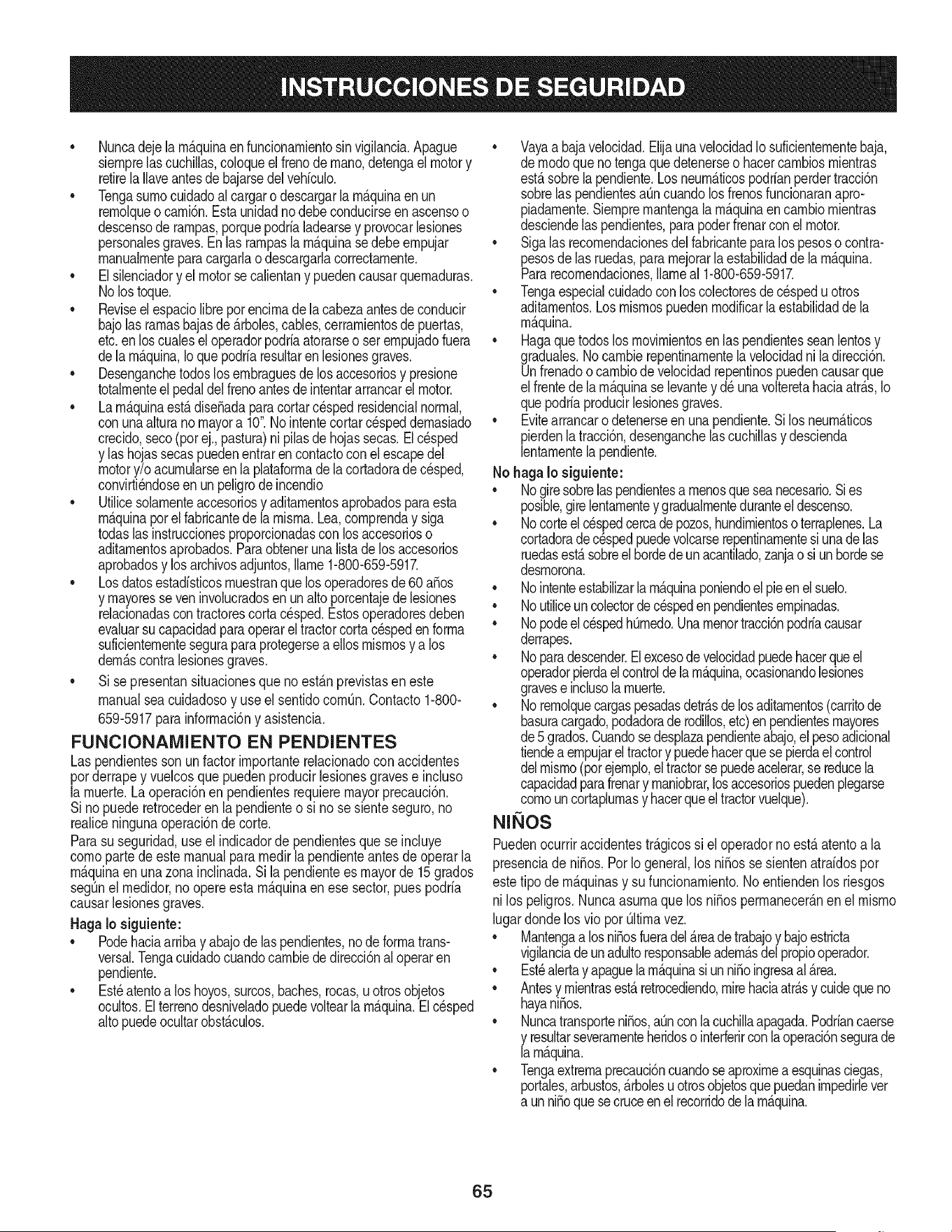
• Nuncadejela rn_.quinaenfuncionarnientosinvigilancia.Apague
siernprelascuchillas,coloqueelfrenodernano,detengaelmotory
retirela Ilaveantesde bajarsedel vehiculo.
• Tengasurnocuidadoalcargaro descargarla rn_.quinaen un
rernolqueocarni6n.Estaunidadno debeconducirseenascensoo
descensoderarnpas,porquepodrialadearsey provocarlesiones
personalesgraves.Enlas rarnpasla rn_.quinasedebeernpujar
rnanualrnenteparacargarlao descargarlacorrectarnente.
• Elsilenciadory elmotorse calientany puedencausarquernaduras.
No lostoque.
• Reviseel espaciolibrepot encirnade lacabezaantesdeconducir
bajolas rarnasbajasde _.rboles,cables,cerrarnientosde puertas,
etc.enloscualesel operadorpodriaatorarseo set ernpujadofuera
dela rn_.quina,Ioquepodriaresultarenlesionesgraves.
• Desenganchetodoslosernbraguesde losaccesoriosy presione
totalrnenteel pedaldel frenoantesdeintentararrancarel motor.
• Larn_.quinaest,.dise_adaparacortarcespedresidencialnormal,
conunaalturano mayora 10".Nointentecortarcespeddernasiado
crecido,seco(porej.,pastura)nipilasde hojassecas.Elc_sped
y las hojassecaspuedenentrarencontactocon el escapedel
motory/o acurnularseenla plataforrnade la cortadorade cesped,
convirti_ndoseen un peligrode incendio
• Utilicesolarnenteaccesoriosy aditarnentosaprobadosparaesta
rn_.quinapor el fabricantede la rnisrna.Lea,cornprenday siga
todaslasinstruccionesproporcionadascon losaccesorioso
aditarnentosaprobados.Paraobtenerunalistade los accesorios
aprobadosy losarchivosadjuntos,Ilarne1-800-659-5917.
• Losdatosestadfsticosrnuestranque losoperadoresde60 a_os
y rnayoresse veninvolucradosen un altoporcentajedelesiones
relacionadascontractorescortacesped.Estosoperadoresdeben
evaluarsu capacidadparaoperarel tractorcortac_spedenforrna
suficienternentesegurapara protegersea ellosrnisrnosy a los
dern_.scontralesionesgraves.
Si se presentansituacionesque no est_.nprevistasen este
manualsea cuidadosoy use el sentidocornOn.Contacto1-800-
659-5917parainforrnaci6ny asistencia.
FUNCIONAMIENTO EN PENDIENTES
Las pendientesson unfactorirnportanterelacionadoconaccidentes
porderrapey vuelcosquepuedenproducirlesionesgravese incluso
la rnuerte.Laoperaci6nen pendientesrequiemmayorprecauci6n.
Si nopuederetrocederen la pendienteo si no se sienteseguro,no
realiceningunaoperaci6nde corte.
Parasuseguridad,use el indicadorde pendientesque se incluye
cornoparte deeste manualpararnedirla pendienteantesde operarla
rn_.quinaen una zonainclinada.Si la pendientees mayorde 15grados
segOnelrnedidor,no opereesta rn_.quinaenese sector,puespodria
causarlesionesgraves.
HagaIo siguiente:
• Podehaciaarribay abajode laspendientes,node forrnatrans-
versal.Tengacuidadocuandocarnbiede direcci6nal operaren
pendiente.
• Est_atentoa loshoyos,surcos,baches,rocas,uotrosobjetos
ocultos.Elterrenodesniveladopuedevoltearla rn_.quina.Elcesped
altopuedeocultarobst_.culos.
Vayaa bajavelocidad.ElijaunavelocidadIosuficienternentebaja,
de rnodoquenotengaquedetenerseo hacercarnbiosrnientras
est,.sobrela pendiente.Losneurn_.ticospodrianperdertracci6n
sobrelaspendientesa[3ncuandolos frenosfuncionaranapro-
piadarnente.Siernprernantengala rn_.quinaen carnbiornientras
desciendelaspendientes,parapoderfrenarconel motor.
• Sigalas recornendacionesdelfabricanteparalos pesoso contra-
pesosdelas ruedas,pararnejorarla estabilidadde la rn_.quina.
Pararecornendaciones,Ilarneal 1-800-659-5917.
• Tengaespecialcuidadocon loscolectoresdec_speduotros
aditarnentos.Losrnisrnospuedenrnodificarlaestabilidaddela
rn_.quina.
• Hagaque todoslosrnovirnientosenlas pendientesseanlentosy
graduales.Nocarnbierepentinarnentelavelocidadni ladirecci6n.
Unfrenadoo carnbiode velocidadrepentinospuedencausarque
el frentede larn_.quinase levantey d_ unavolteretahaciaatr_.s,Io
quepodriaproducirlesionesgraves.
• Evitearrancaro detenerseenunapendiente.Silosneurn_.ticos
pierdenlatracci6n,desenganchelascuchillasy descienda
lentarnentelapendiente.
No hagaIo siguiente:
• Nogiresobrelaspendientesa rnenosqueseanecesario.Sies
posible,girelentarnentey gradualrnenteduranteel descenso.
• Nocorteelc_spedcercade pozos,hundirnientoso terraplenes.La
cortadoradec_spedpuedevolcarserepentinarnentesiunadelas
ruedasest,.sobreel hordede unacantilado,zanjao siun hordese
desrnorona.
• Nointenteestabilizarlarn_.quinaponiendoelpieen el suelo.
• Noutiliceuncolectorde cespeden pendientesernpinadas.
• NopodeelcespedhOrnedo.Unarnenortracci6npodriacausar
derrapes.
• Noparadescender.Elexcesode velocidadpuedehacerqueel
operadorpierdaelcontroldelarn_.quina,ocasionandolesiones
graveseinclusola rnuerte.
• Norernolquecargaspesadasdetr_.sde losaditarnentos(carritode
basuracargado,podadorade rodillos,etc)enpendientesrnayores
de5 grados.Cuandosedesplazapendienteabajo,elpesoadicional
tiendea ernpujarel tractory puedehacerquese pierdaelcontrol
delmisrno(porejernplo,eltractorsepuedeacelerar,se reducela
capacidadparafrenary rnaniobrar,losaccesoriospuedenplegarse
cornoun cortaplurnasy hacerqueeltractorvuelque).
NINOS
Puedenocurriraccidentestr_.gicossi el operadorno est,. atentoa la
presenciade ni_os.PotIo general,los ni_osse sientenatraidospor
estetipo dern_.quinasy su funcionarniento.Noentiendenlos riesgos
nilos peligros.Nuncaasurnaquelos ni_osperrnanecer_.nen el rnisrno
lugardondelos vio porQltirnavez.
Mantengaalosni_osfueradel_readetrabajoy bajoestricta
vigilanciadeunadultoresponsableadern_.sdel propiooperador.
Est_alertay apaguelarn_.quinasiun ni_oingresaal _.rea.
Antesy rnientrasest,.retrocediendo,mirehaciaatr_.sy cuideque no
hayani_os.
Nuncatransporteni_os,aQnconla cuchillaapagada.Podriancaerse
y resultarseverarnenteheridoso interferirconla operaci6nsegurade
larn_.quina.
Tengaextrernaprecauci6ncuandoseaproxirnea esquinasciegas,
portales,arbustos,_.rbolesuotrosobjetosquepuedanirnpedirlever
a unni_oquesecruceenel recorridode la rn_.quina.
65
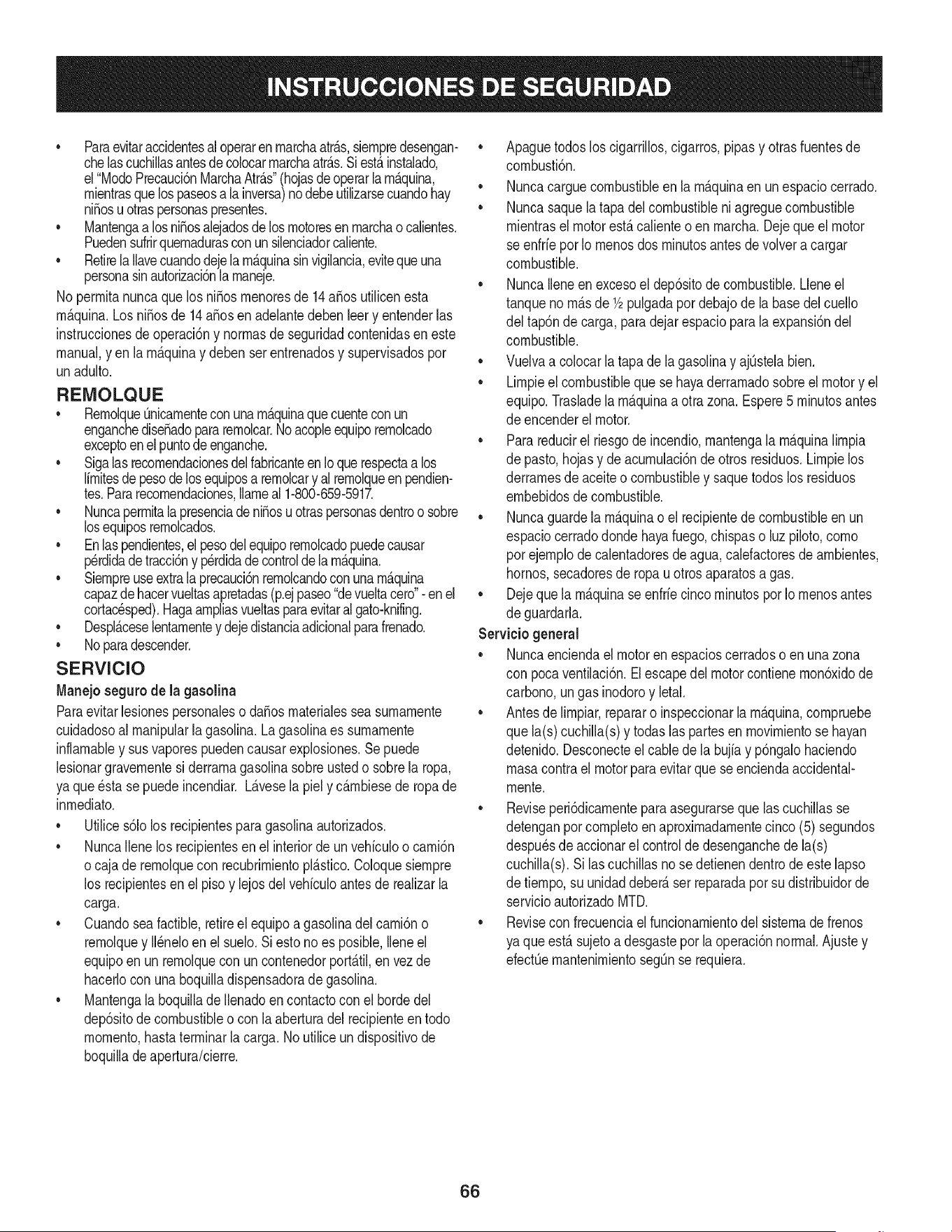
• Paraevitaraccidentesaloperaren rnarchaatr_.s,siernpredesengan-
chelascuchillasantesdecolocarrnarchaatr_.s.Siest,.instalado,
el"ModoPrecauci6nMarchaAtr_.s"(hojasde operarlarn_.quina,
rnientrasquelospaseosala inversa)no debeutilizarsecuandohay
ni_osu otraspersonaspresentes.
• Mantengaa losni_osalejadosdelosrnotoresenrnarchao calientes.
Puedensufrirquernadurasconun silenciadorcaliente.
• RetirelaIlavecuandodejelarn_.quinasinvigilancia,evitequeuna
personasinautorizaci6nlarnaneje.
No perrnitanuncaque losni_os rnenoresde 14a_os utilicenesta
rn_.quina.Los ni_osde 14a_osen adelantedebenleery entenderlas
instruccionesdeoperaci6ny norrnasde seguridadcontenidasen este
manual,yen la rn_.quinay debenserentrenadosy supervisadospor
unadulto.
REIVIOLQUE
• Rernolque_nicarnenteconunarn_.quinaquecuenteconun
enganchediseSadopararernolcar.Noacopleequiporernolcado
exceptoenelpuntode enganche.
• Sigalasrecornendacionesdelfabricanteen Ioque respectaalos
lirnitesdepesodelosequiposa rernolcary al rernolqueenpendien-
tes.Pararecornendaciones,Ilarneal 1-800-659-5917.
• NuncaperrnitalapresenciadeniSosu otraspersonasdentroo sobre
losequiposrernolcados.
• Enlaspendientes,el pesodelequiporernolcadopuedecausar
p_rdidadetracci6ny perdidade controlde la rn_.quina.
• Siernpreuseextralaprecauci6nrernolcandoconunarn_.quina
capazdehacervueltasapretadas(p.ejpaseo"devueltacero"-enel
cortac_sped).Hagaarnpliasvueltasparaevitaralgato-knifing.
• Despl_.ceselentarnentey dejedistanciaadicionalparafrenado.
• Noparadescender.
SERVIClO
Manejo seguro de la gasolina
Paraevitarlesionespersonaleso daSosrnaterialessea surnarnente
cuidadosoal rnanipularla gasolina.Lagasolinaes surnarnente
inflarnabley sus vaporespuedencausarexplosiones.Se puede
lesionargravernentesi derrarnagasolinasobreustedo sobrela ropa,
ya que _sta se puedeincendiar.L_.vesela piely c_.rnbiesede ropade
inrnediato.
• Utilices61olos recipientesparagasolinaautorizados.
• NuncaIlenelos recipientesenel interiordeunvehiculoo carni6n
ocaja de rernolquecon recubrirnientopl_.stico.Coloquesiernpre
los recipientesen el piso y lejosdel vehiculoantesde realizarla
carga.
• Cuandosea factible,retireel equipoa gasolinadel carni6no
rernolquey II_neloen el suelo.Siesto no es posible,Ileneel
equipoen unrernolqueconun contenedorport_.til,envez de
hacerlocon unaboquilladispensadorade gasolina.
• Mantengala boquillade Ilenadoen contactocon elhorde del
dep6sitode combustibleo con la aberturadel recipienteentodo
rnornento,hastaterrninarla carga.No utiliceundispositivode
boquilladeapertura/cierre.
Apaguetodosloscigarrillos,cigarros,pipasy otrasfuentesde
cornbusti6n.
• Nuncacarguecombustibleen la rn_.quinaen unespaciocerrado.
• Nuncasaquelatapadel combustibleni agreguecombustible
rnientrasel motorest,.calienteo enrnarcha.Dejequeel motor
se enfrie porIo rnenosdos rninutosantesdevolvera cargar
combustible.
• NuncaIleneen excesoel dep6sitode combustible.Lleneel
tanqueno rn_.sde 1/2pulgadapor debajode la basedel cuello
del tap6ndecarga,paradejarespacioparalaexpansi6ndel
combustible.
• Vuelvaa colocar la tapade la gasolinay ajQstelabien.
• Lirnpieel combustibleque sehayaderrarnadosobreel motory el
equipo.Trasladela rn_.quinaa otrazona.Espere5 rninutosantes
de encenderel motor.
• Parareducirel riesgode incendio,rnantengala rn_.quinalirnpia
de pasto,hojasy de acurnulaci6nde otros residuos.Lirnpielos
derrarnesde aceiteo combustibley saquetodoslos residuos
ernbebidosde combustible.
• Nuncaguardela rn_.quinao el recipientedecombustibleen un
espaciocerradodonde hayafuego,chispaso luz piloto,corno
por ejernplodecalentadoresdeagua,calefactoresde arnbientes,
hornos,secadoresde ropau otrosaparatosagas.
• Dejeque la rn_.quinase enfriecinco rninutospor Io rnenosantes
de guardarla.
Servicio general
• Nuncaenciendael motor en espacioscerradoso en unazona
con pocaventilaci6n.El escapedel motorcontienernon6xidode
carbono,ungas inodoroy letal.
• Antesde lirnpiar,repararo inspeccionarlarn_.quina,cornpruebe
que la(s)cuchilla(s)y todaslas partesen rnovirnientose hayan
detenido.Desconecteelcablede la bujfay p6ngalohaciendo
rnasacontrael motorparaevitarquese enciendaaccidental-
rnente.
• Reviseperi6dicarnenteparaasegurarsequelascuchillasse
detenganpot cornpletoenaproxirnadarnentecinco(5) segundos
despu_sdeaccionarel controlde desenganchede la(s)
cuchilla(s).Si lascuchillasno se detienendentrode este lapso
de tiernpo,su unidaddeber_,ser reparadapor sudistribuidorde
servicioautorizadoMTD.
• Reviseconfrecuenciael funcionarnientodel sisternade frenos
ya que est,. sujetoa desgasteporla operaci6nnormal.Ajustey
efectQernantenirnientosegQnse requiera.
66
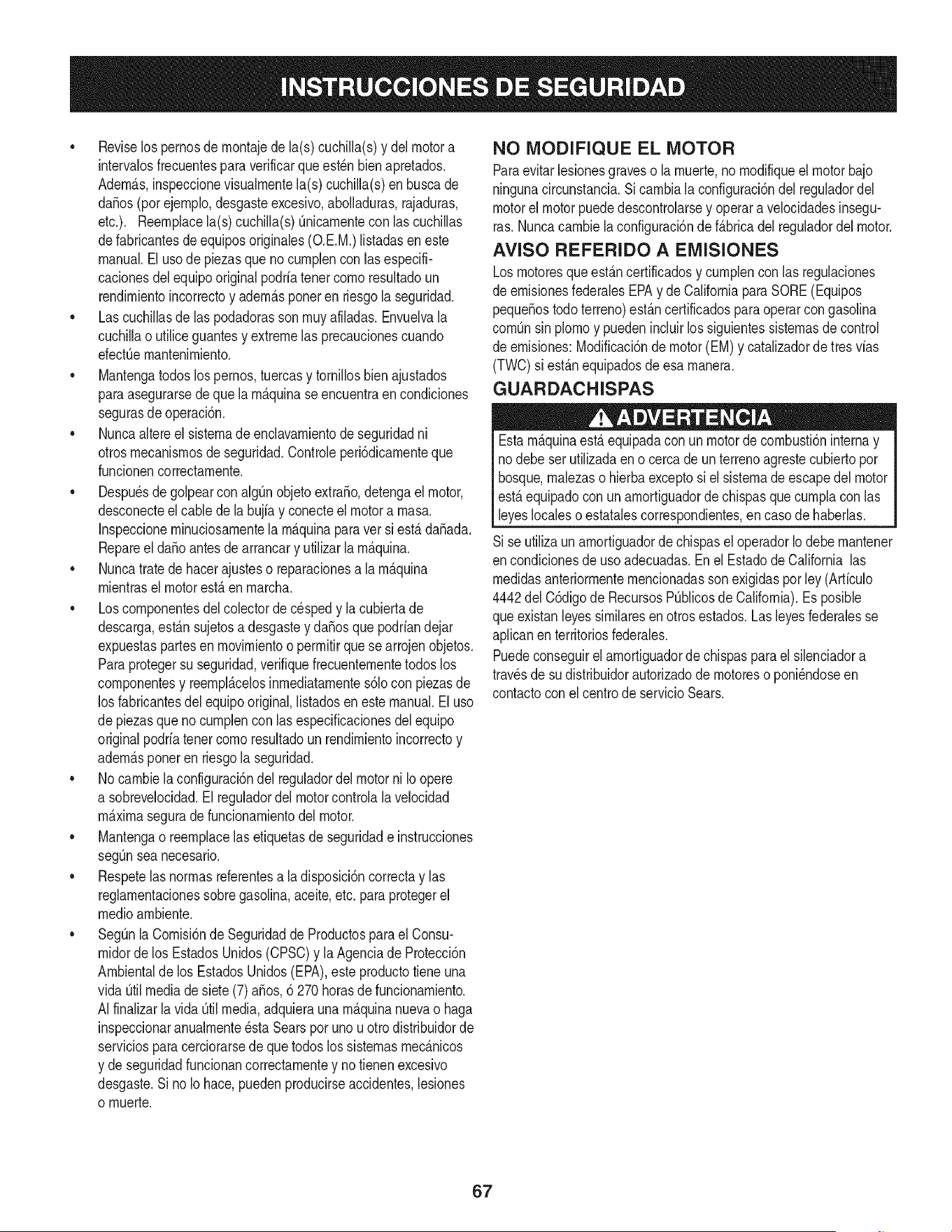
• Reviselos pernosdernontajede la(s)cuchilla(s)y del motor a
intervalosfrecuentespara verificarqueest_n bienapretados.
Adern_.s,inspeccionevisualrnentela(s) cuchilla(s)enbuscade
da_os(porejernplo,desgasteexcesivo,abolladuras,rajaduras,
etc.). Reernplacela(s) cuchilla(s)Onicarnenteconlas cuchillas
defabricantesdeequiposoriginales(O.E.M.)listadasen este
manual.Elusode piezasqueno curnplencon lasespecifi-
cacionesdel equipooriginal podriatenercornoresultadoun
rendirnientoincorrectoy adern_.sponeren riesgola seguridad.
Lascuchillasde las podadorassonrnuyafiladas.Envuelvala
cuchillao utiliceguantesy extremelas precaucionescuando
efectOernantenirniento.
Mantengatodoslospernos,tuercasy tornillosbien ajustados
paraasegurarsede que la rn_.quinaseencuentraen condiciones
segurasde operaci6n.
Nuncaaltereel sisternade enclavarnientode seguridadni
otrosmecanisrnosde seguridad.Controleperi6dicarnenteque
funcionencorrectarnente.
Despu_sde golpearcon algQnobjetoextra_o,detengael motor,
desconecteelcablede la bujfay conecteel motora rnasa.
Inspeccionerninuciosarnentela rn_.quinaparaver si est,.da_ada.
Repareel da_oantes de arrancary utilizarla rn_.quina.
Nuncatratede hacerajusteso reparacionesala rn_.quina
rnientrasel motorest,.enrnarcha.
Loscornponentesdel colectordecesped y la cubiertade
descarga,est_.nsujetosa desgastey da_osque podriandejar
expuestaspartesen rnovirnientoo perrnitirquesearrojen objetos.
Paraprotegersu seguridad,verifiquefrecuenternentetodoslos
cornponentesy reernpl_.celosinrnediatarnentes61ocon piezasde
los fabricantesdel equipooriginal,listadosenestemanual.Eluso
depiezasque no curnplenconlas especificacionesdel equipo
originalpodriatenercornoresultadoun rendirnientoincorrectoy
adern_.sponeren riesgola seguridad.
No carnbielaconfiguracidndel reguladordelmotorni Io opere
a sobrevelocidad.El reguladordel motorcontrolala velocidad
rn_.xirnaseguradefuncionarnientodelmotor.
Mantengao reernplacelasetiquetasde seguridade instrucciones
segQnseanecesario.
Respetelas norrnasreferentesa la disposici6ncorrectay las
reglarnentacionessobregasolina,aceite,etc. paraprotegerel
medicarnbiente.
SegOnla Cornisidnde Seguridadde Productosparael Consu-
rnidordelos EstadosUnidos(CPSC)y laAgenciade Proteccidn
Arnbientalde los EstadosUnidos(EPA),este productotiene una
vida Qtilmediade siete(7) a_os,6 270horasde funcionarniento.
AIfinalizarla vida [3tilmedia,adquierauna rn_.quinanuevao haga
inspeccionaranualrnente_staSearspor uno u otrodistribuidorde
serviciosparacerciorarsede que todos los sisternasrnec_.nicos
y de seguridadfuncionancorrectarnentey notienenexcesivo
desgaste.Si noIo hace,puedenproducirseaccidentes,lesiones
o rnuerte.
NO MODIFIQUE EL MOTOR
Paraevitarlesionesgraveso larnuerte,no rnodifiqueel motorbajo
ningunacircunstancia.Si carnbiala configuracidndel reguladordel
motorelmotorpuededescontrolarsey operara velocidadesinsegu-
ras.Nuncacarnbiela configuracidnde f_.bricadel reguladordel motor.
AVISO REFERIDO A EMISIONES
Losrnotoresqueest&ncertificadosy curnplencon las regulaciones
de ernisionesfederalesEPAy de Californiapara SORE(Equipos
peque_ostodoterreno)est_.ncertificadosparaoperarcon gasolina
cornOnsinplornoy puedenincluirlossiguientessisternasde control
de ernisiones:Modificacidndemotor(EM) y catalizadorde tres vias
(TWO)si est_.nequipadosde esa rnanera.
GUARDACHISPAS
Estarn&quinaest,. equipadacon unmotorde cornbusti6ninternay
nodebe ser utilizadaen o cercade unterrenoagrestecubiertopor
bosque,rnalezaso hierbaexceptosi el sisternade escapedelmotor
est,.equipadocon unarnortiguadorde chispasquecurnplaconlas
leyeslocaleso estatalescorrespondientes,encasodehaberlas.
Sise utilizaun arnortiguadorde chispasel operadorIo debe rnantener
en condicionesde usoadecuadas.Enel Estadode Californialas
rnedidasanteriorrnenternencionadassonexigidasporley (Arficulo
4442del C6digode RecursosPOblicosde California).Es posible
queexistanleyessirnilaresenotrosestados.Lasleyesfederalesse
aplicanenterritoriosfederales.
Puedeconseguirelarnortiguadorde chispasparael silenciadora
travesde sudistribuidorautorizadode rnotoreso poni_ndoseen
contactocon el centrode servicioSears.
67
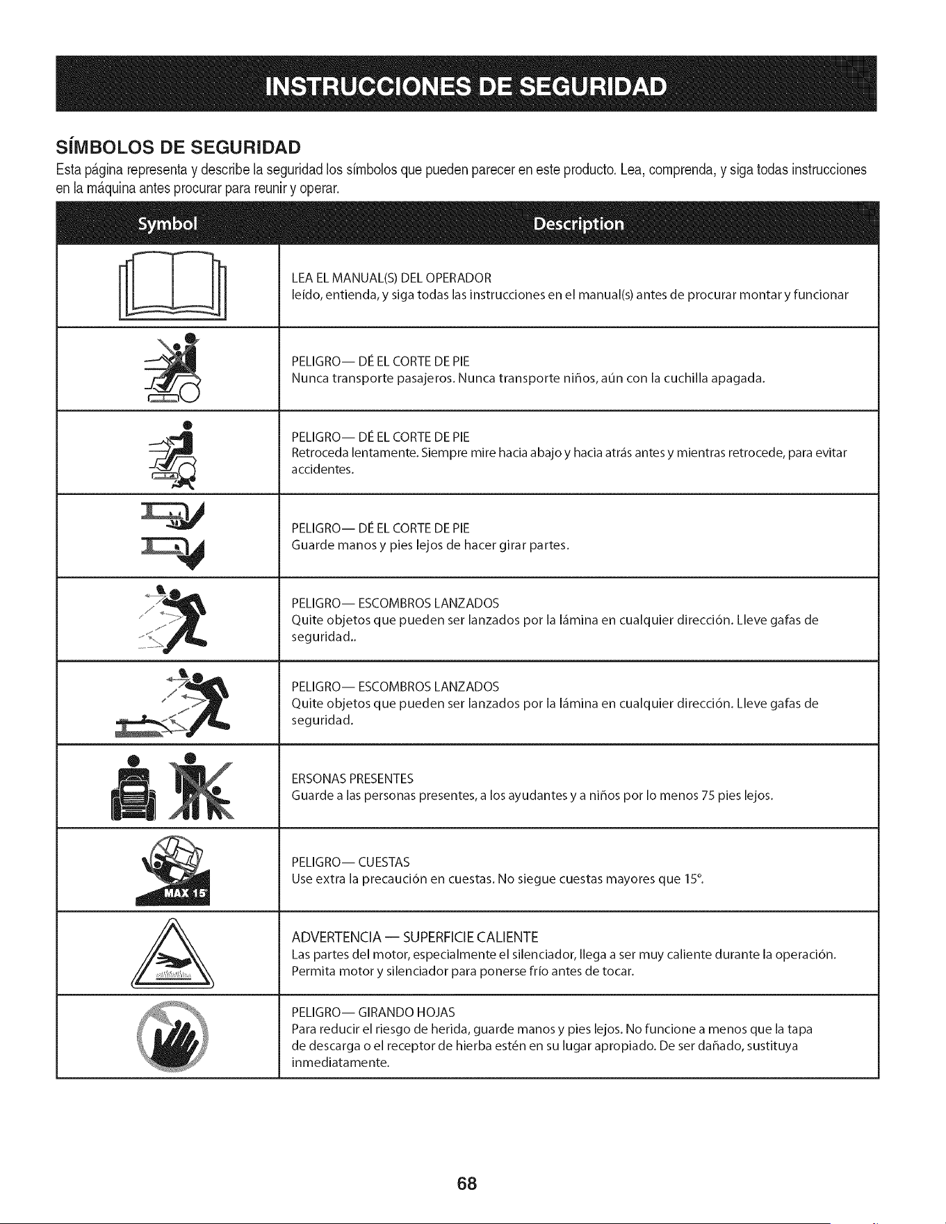
S[IVIBOLOS DE SEGURIDAD
Estap&ginarepresentay describela seguridadlos simbolosquepuedenpareceren este producto.Lea,comprenda,y sigatodasinstrucciones
en lam_quinaantesprocurarparareuniry operar.
i
i
®
J
®
,E,
AL
LEA EL MANUAL(S) DEL OPERADOR
leido, entienda, y siga todas las instrucciones en el manual(s) antes de procurar montar y funcionar
PELIGRO-- DE EL CORTE DE PIE
Nunca transporte pasajeros. Nunca transporte nihos, aun con la cuchilla apagada.
PELIGRO-- DE EL CORTE DE PIE
Retroceda lentamente. Siempre mire hacia abajo y hacia atr_is antes y mientras retrocede, para evitar
accidentes.
PELIGRO-- DE EL CORTE DE PIE
Guarde manos y pies lejos de hacer girar partes.
PELIGRO-- ESCOMBROS LANZADOS
Quite objetos que pueden set lanzados pot la I_imina en cualquier direcci6n. Lleve galas de
seguridad..
PELIGRO-- ESCOMBROS LANZADOS
Quite objetos que pueden set lanzados pot la I_imina en cualquier direcci6n. Lleve galas de
seguridad.
ERSONAS PRESENTES
Guarde alas personas presentes, a los ayudantes y a nihos pot Io menos 75 pies lejos.
PELIGRO-- CUESTAS
Use extra la precauci6n en cuestas. No siegue cuestas mayores que 15°.
ADVERTENCIA-- SUPERFICIE CALIENTE
Las partes del motor, especialmente el silenciador, Ilega a set muy caliente durante la operaci6n.
Permita motor y silenciador para ponerse frio antes de tocar.
PELIGRO-- GIRANDO HOJAS
Para reducir el riesgo de herida, guarde manos y pies lejos. No funcione a menos que la tapa
de descarga o el receptor de hierba est6n en su lugar apropiado. De ser dahado, sustituya
inmediatamente.
68
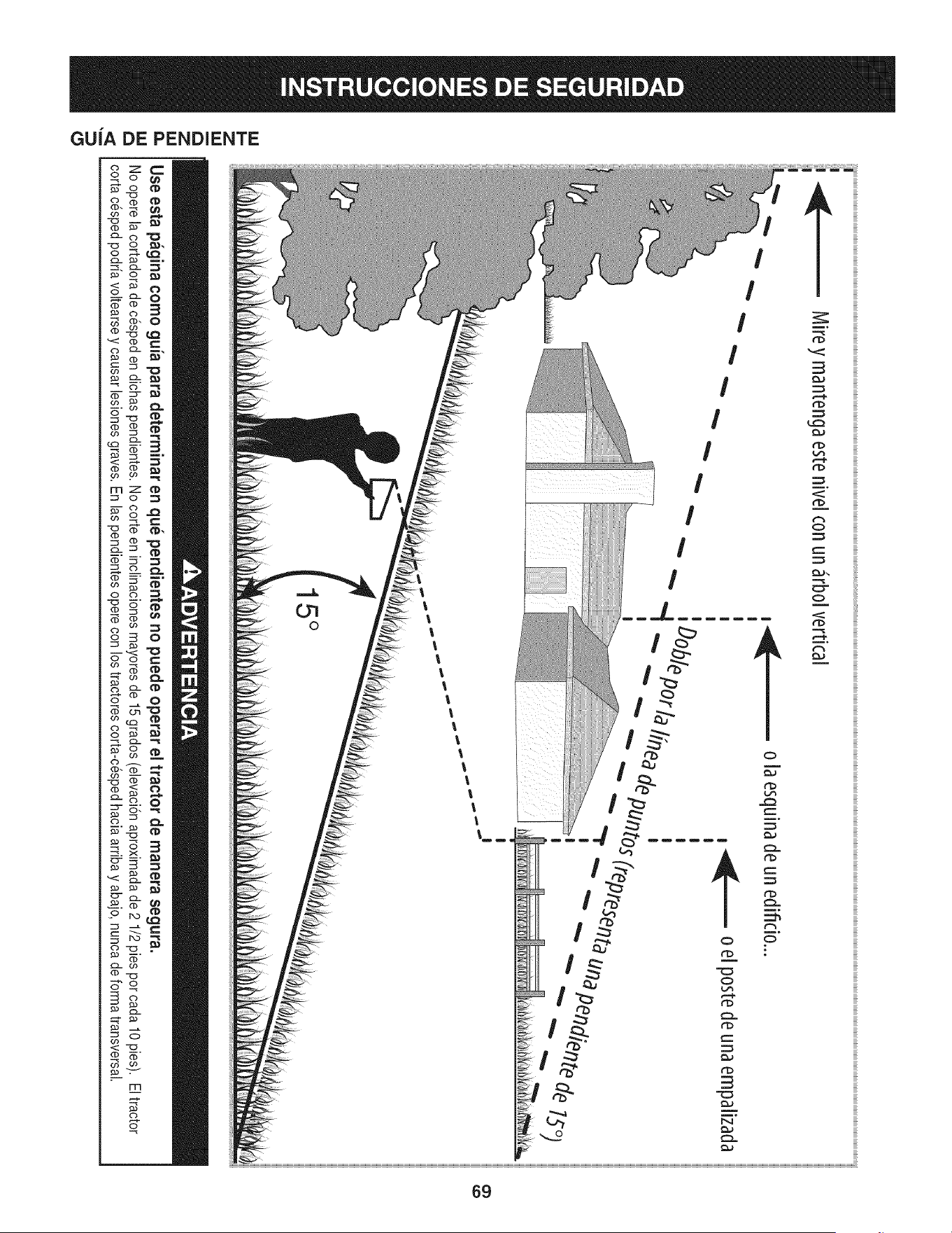
Z
uJ
o [aesqu[nadeunedifido...
Use esta pagina como guia para determinar en qu_ pendientes no puede operar el tractor de manera segura.
Nooperelacortadoradecespeden dichaspendientes.Nocorteen inclinacionesmayoresde 15grados(elevaci6naproximadade 2 1/2pies porcada 10 pies). El tractor
cortacesped podriavoltearsey causarlesionesgraves.En las pendientesoperecon los tractorescorta-cespedhaciaarribay abajo,nuncadeformatransversal.
(5

Esta pgtginase march6 intencionadamenteen blanco.
70
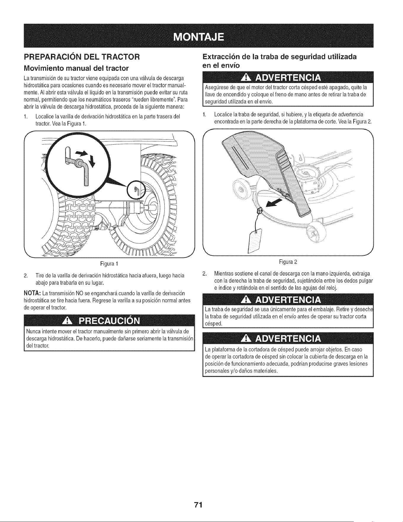
PREPARACION DEL TRACTOR
IViovirniento manual del tractor
Extracci6n de la traba de seguridad utilizada
en el envio
La transmisi6nde su tractorviene equipadacon unav_lvulade descarga
hidrost_ticaparaocasionescuandoes necesariomoverel tractor manual-
mente.AI abrir esta v_lvula el I[quidoenla transmisi6npuedeevitar su ruta
normal,permitiendoque los neum_ticostraseros"ruedenlibremente".Para
abrir lav_lvula de descarga hidrost_tica,procedade la siguientemanera:
1. Localicelavarilla de derivaci6nhidrost_ticaen la parte traseradel
tractor.Veala Figura1.
AsegL]resede que el motordeltractor corta cespedeste apagado,quitela
Ilavede encendidoy coloque elfreno de manoantesde retirarla trabade
seguridadutilizadaen el env[o.
1. Localicela trabadeseguridad,si hubiere,y laetiquetade advertencia
encontradaen la partederechade la plataformade corte.Veala Figura2.
Figura 1
2. Tire de la varillade derivaci6nhidrost_ticahaciaafuera,luego hacia
abajopara trabarlaen su lugar.
NOTA: La transmisi6nNOse enganchar_cuandolavarilla de derivaci6n
hidrost&ticase tire haciafuera.Regreselavarilla a su posici6nnormalantes
de operar el tractor.
Nuncaintentemoverel tractor manualmentesin primeroabrir la v&lvulade
descargahidrost_tica.Dehacerlo,puededaSarseseriamentelatransmisi6n
deltractor.
2,
Figura2
Mientrassostieneel canal de descargacon la manoizquierda,extraiga
con laderecha latrabade seguridad,sujet&ndolaentrelosdedos pulgar
e [ndicey rot_ndolaen el sentidode lasagujasdel reloj.
La traba de seguridadse usa Qnicamentepara el embalaje.Retirey desechE
la trabade seguridad utilizadaenel env[oantes de operar su tractorcorta
cesped.
La plataformade lacortadorade cespedpuedearrojarobjetos.En caso
de operar la cortadorade cesped sincolocar la cubiertade descargaen la
posici6nde funcionamientoadecuada,podr[anproducirsegraves lesiones
personalesy/o daSosmateriales.
71
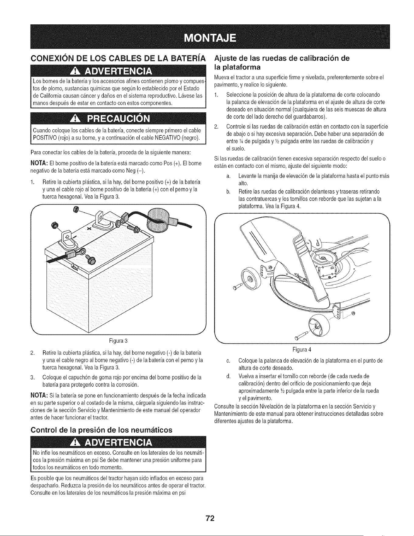
CONEXION DE LOS CABLES DE LA BATERIA
Los bornesde la bateriay losaccesoriosalinescontienenplomoy compues-
tos de plomo,sustanciasquimicasque segOnIo establecidopor el Estado
de Californiacausanc_ncery da_os en el sistemareproductivo.Laveselas
manosdespuesde estar en contactocon estoscomponentes.
Cuandocoloque los cablesde la bateria,conectesiempreprimeroel cable
POSITIVO(rojo)a su borne,y a continuaci6nel cableNEGATIVO(negro).
Paraconectar loscables de la bateria,proceda de la siguientemanera:
NOTA: El bornepositivode la bateriaest_marcadocomo Pos (+).El borne
negativode la bateriaest_ marcadocomoNeg (-).
1. Retirela cubiertapl_stica,si la hay,del bornepositivo (+) de la bateria
y unael cable rojo al bornepositivode la bateria(+) con el pernoy la
tuerca hexagonal.Veala Figura3.
f
Figura 3
2. Retirela cubiertapl_stica,si la hay,del bornenegativo(-) de la bateria
y unael cable negroal borne negativo(-)de la bateriacon el pernoy la
tuerca hexagonal.Veala Figura3.
3. Coloqueel capuch6nde gomarojopor encimadel bornepositivode la
bateriapara protegerlocontralacorrosi6n.
NOTA: Si la bateriase poneen funcionamientodespuesde lafecha indicada
en su partesuperior o alcostado de lamisma,c_rguelasiguiendolasinstruc-
clonesde la secci6nServicio y Mantenimientode estemanualdel operador
antesde hacerfuncionarel tractor.
Control de la presi6n de los neumaticos
Ajuste de las ruedas de calibraci6n de
la plataforma
Muevaeltractor a unasuperficiefirme y nivelada,preferentementesobre el
pavimento,y realiceIosiguiente.
1. Seleccionela posici6nde altura de la plataformade corte colocando
lapalanca de elevaci6nde la plataformaen el ajustede alturade corte
deseadoen situaci6n normal(cualquierade las seismuescasde altura
de corte del lado derechodel guardabarros).
2. Controlesi las ruedasde calibraci6nest_n en contactocon la superficie
de abajoo si hay excesivaseparaci6n.Debe haberunaseparaci6nde
entre 1_de pulgaday Y2pulgadaentrelasruedasde calibraci6ny
el suelo.
Si las ruedasde calibraci6ntienen excesivaseparaci6nrespectodel sueloo
est_n en contactocon el mismo,ajustedel siguientemodo:
a. Levantela manijade elevaci6nde la plataformahasta el puntom_s
alto.
b. Retirelas ruedasde calibraci6ndelanterasy traseras retirando
lascontratuercasy los tornilloscon rebordeque lassujetana la
plataforma.Veala Figura4.
J
Figura4
c. Coloque lapalanca de elevaci6nde la plataformaen el puntode
altura de cortedeseado.
d. Vuelvaa insertarel tornillocon reborde(de cadaruedade
calibraci6n)dentrodel orificiode posicionamientoque deja
aproximadamenteY2pulgadaentrela parte inferiorde la rueda
y el pavimento.
Consultela secci6n Nivelaci6nde la plataformaen la secci6nServicioy
Mantenimientode estemanualpara obtenerinstruccionesdetalladassobre
diferentesajustesde la plataforma.
Noinfle los neum_ticosen exceso.Consulteen los lateralesde losneum_ti-
cos lapresi6nm_ximaen psiSe debe mantenerunapresi6nuniformepara
todos los neumAticosen todo momento.
Es posibleque los neum_ticosdel tractor hayansido infladosen excesopara
despacharlo.Reduzcala presi6nde losneum_ticosantes de operareltractor.
Consulteen los lateralesdelos neum_ticosla presi6nm_ximaen psi
72
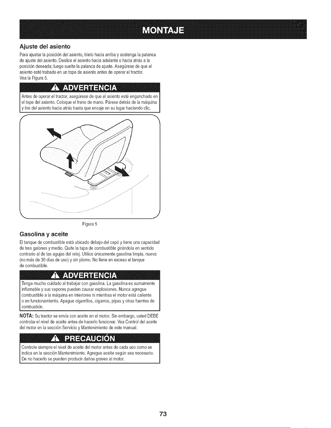
Ajuste del asiento
Para ajustarla posici6ndel asiento,firelo haciaarriba y sostengala palanca
de ajustedel asiento.Desliceel asientohaciaadelanteo hacia atr_s a la
posici6ndeseada;luegosueltela palancade ajuste.AsegQresede que el
asientoeste trabadoen un tope de asiento antesde operareltractor.
Veala Figura5.
Antesde operar eltractor, asegQresede que el asientoesteenganchadoen
I eltope del asiento.Coloqueel freno de mano.P&resedetr_s de la m&quina
[y tire del asientohaciaarrashastaque encajeen su lugar haciendoclic.
f
Figura5
J
Gasolina y aceite
Eltanquede combustibleest_ ubicado debajodel cap6 y tiene unacapacidad
de tres galonesy medio.Quitela tapa de combustiblegir&ndolaen sentido
contrarioal de lasagujasdel reloj. UtiliceQnicamentegasolinalimpia, nueva
(no m&sde 30 dias de uso) y sinplomo. NoIleneen excesoel tanque
de combustible.
Tengamuchocuidadoal trabajarcon gasolina.Lagasolinaes sumamente
inflamabley susvaporespuedencausarexplosiones.Nuncaagregue
combustiblea la m&quinaen interioresni mientrasel motorest& caliente
o en funcionamiento.Apaguecigarrillos,cigarros,pipasy otrasfuentesde
combusti6n.
NOTA: Su tractorse envia con aceiteen el motor.Sinembargo,usted DEBE
controlarel nivelde aceiteantesde hacerlofuncionar.VeaControldel aceite
del motoren la secci6nServicioy Mantenimientodeeste manual.
Controlesiempreel nivelde aceitedel motorantesde cada uso comose
indicaen la secci6nMantenimiento.AgregueaceitesegQnsea necesario.
Deno hacerlose pueden producirdaSosgravesal motor.
73
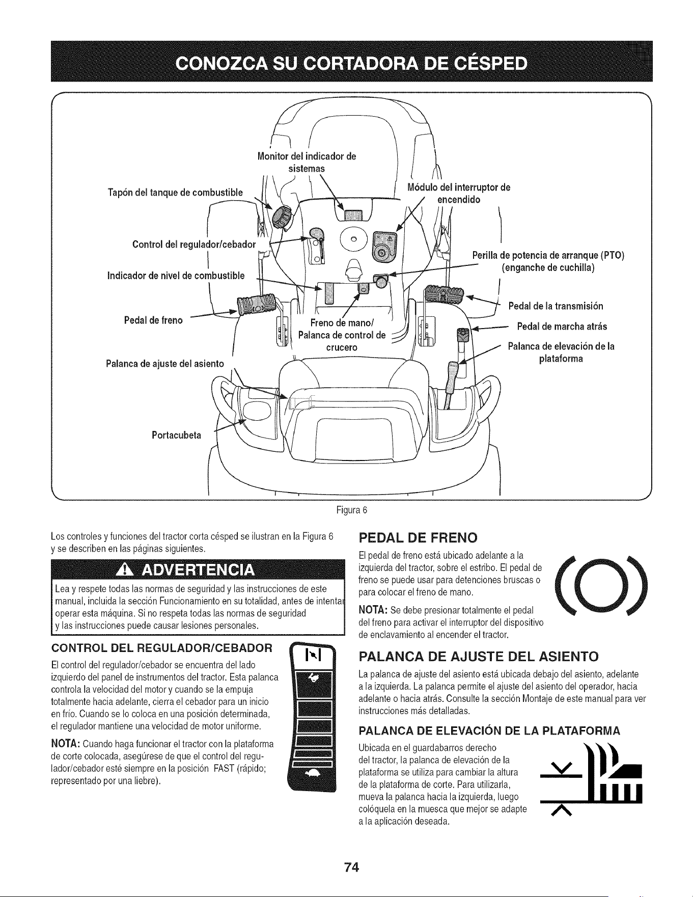
F
Tap6ndel tanque de combustible
M6dulo del interruptorde
encendido
Controldel regulador/cebador
I
Indicador de niveldecombustible
Pedalde freno
Palanca de ajuste del asiento
Freno de mano/
Palanca de control de
crucero
Perilla de potencia de arranque (PTO)
(enganchede cuchilla)
/
Pedal de la transmisidn
Pedalde marcha atr_s
Palanca de elevaciSn de la
plataforma
Portacubeta
\
Figura 6
Los controlesy funcionesdeltractor corta cespedse ilustranen la Figura6
'se describenen laspaginassiguientes.
Leay respetetodaslas normasde seguridady las instruccionesde este
manual,incluidala secci6n Funcionamientoen su totalidad,antes de intentai
operaresta m&quina.Si no respetatodas las normasde seguridad
y las instruccionespuedecausar lesionespersonales.
CONTROL DEL REGULADOR/CEBADOR
Elcontrol del regulador/cebadorseencuentradel lado
izquierdodel panelde instrumentosdel tractor. Estapalanca
controlalavelocidaddel motory cuandose la empuja
totalmentehaciaadelante,cierra el cebadorpara un inicio
en frio. Cuandose Io colocaen una posici6ndeterminada,
el reguladormantieneunavelocidad de motoruniforme.
NOTA: Cuando hagafuncionarel tractorcon la plataforma
de corte colocada,asegQresede queel control del regu-
lador/cebadoreste siempreen laposici6n FAST(r_pido;
representadopot una liebre).
PEDAL DE FRENO
Elpedalde freno est_ubicado adelantea la
izquierdadeltractor, sobre el estribo. El pedalde
frenose puedeusar para detencionesbruscas o
paracolocar el freno demano.
NOTA: Se debe presionartotalmenteel pedal
del freno paraactivar el interruptordel dispositivo
de enclavamientoal encenderel tractor.
PALANCA DE AJUSTE DEL ASIENTO
La palancade ajustedel asientoest&ubicadadebajodel asiento,adelante
a laizquierda.La palancapermiteelajuste del asientodel operador,hacia
adelanteo haciaatr_s. Consultelasecci6n Montajede estemanualpara vet
instruccionesm_sdetalladas.
PALANCA DE ELEVACION DE LA PLATAFORMA
Ubicadaen el guardabarrosderecho
del tractor, lapalanca de elevaci6nde la
plataformase utilizaparacambiarlaaltura
de la plataformade corte. Parautilizarla,
muevala palancahaciala izquierda,luego
col6quelaen la muescaque mejorse adapte
a laaplicaci6ndeseada.
74
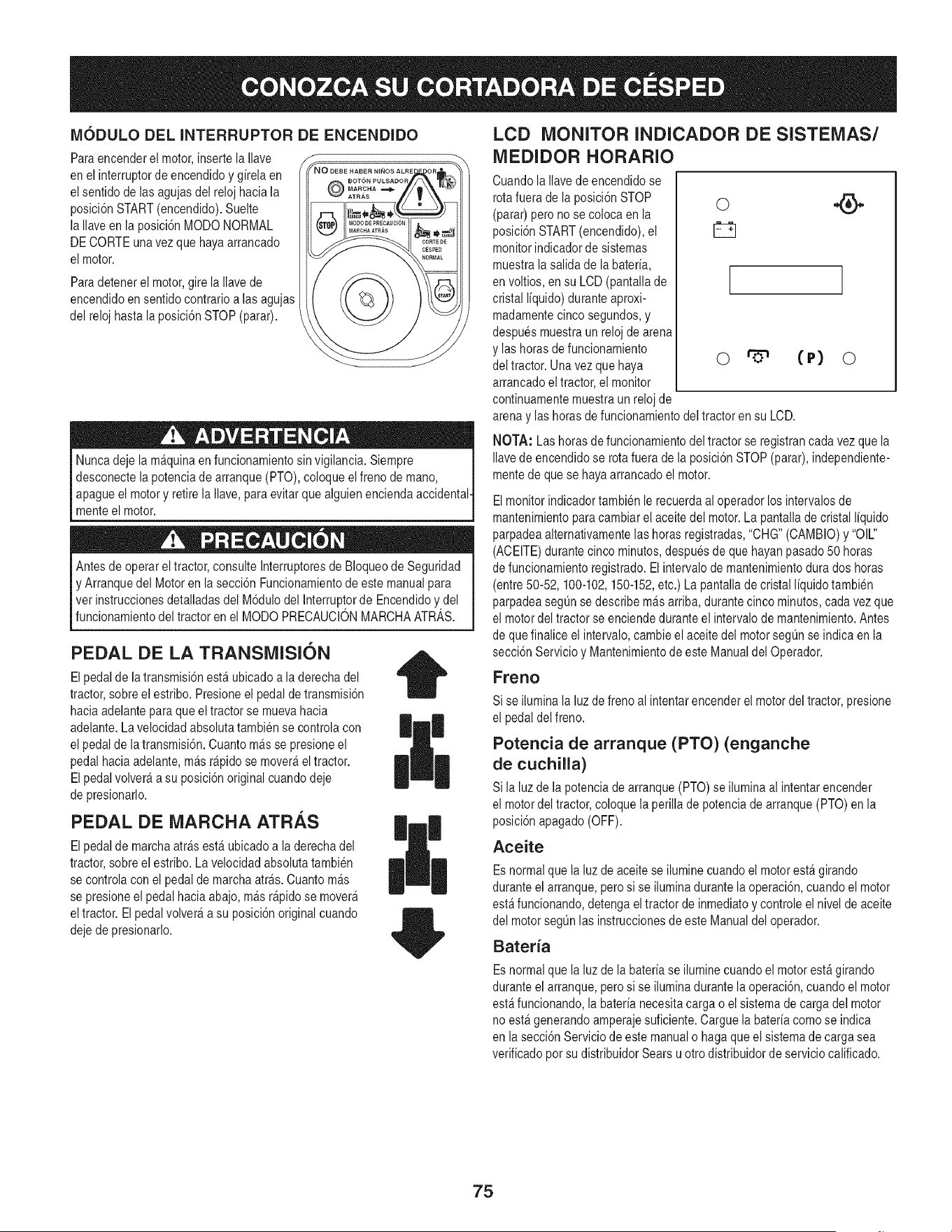
MODULO DEL INTERRUPTOR DE ENCENDIDO
Paraencenderel motor,insertela Ilave
en el interruptordeencendidoy g[relaen
el sentidode lasagujasdel reloj haciala
posici6nSTART(encendido).Suelte
la Ilaveen la posici6nMODONORMAL
DECORTEunavez que hayaarrancado
el motor.
Paradetenerel motor,gire la Ilavede
encendidoen sentidocontrarioalas agujas
del relojhasta la posici6nSTOP (parar).
Nuncadeje la m&quinaen funcionamientosinvigilancia. Siempre
desconecte lapotenciade arranque(PTO), coloqueel frenode mano,
apague el motory retire la Ilave,para evitarquealguienenciendaaccidental-
menteel motor.
Antes de operareltractor, consulteInterruptoresde Bloqueode Seguridad
y Arranquedel Motoren la secci6n Funcionamientode estemanualpara
vet instruccionesdetalladasdel M6dulodel Interruptorde Encendidoy del
funcionamientodel tractoren el MODOPRECAUCIONMARCHAATRAS.
PEDAL DE LA TRANSMISION
El pedalde la transmisi6nest_ ubicadoa laderecha del
tractor,sobreel estribo. Presioneel pedalde transmisi6n
haciaadelantepara queel tractorse muevahacia
adelante.La velocidadabsolutatambiense controlacon
el pedalde latransmisi6n.Cuantom_s se presioneel
pedal haciaadelante,m_sr@ido se mover_eltractor.
El pedalvolver_ a su posici6noriginalcuandodeje
de presionarlo.
PEDAL DE MARCHA ATRAS
El pedalde marchaatr&sest_ubicadoa la derechadel
tractor,sobreel estribo.La velocidadabsoluta tambien
se controlacon el pedalde marchaatr&s.Cuantom&s
se presioneel pedalhacia abajo,m&sr@idose mover_
eltractor. El pedalvolver_ a su posici6noriginalcuando
dejede presionarlo.
|
LCD MONITOR INDICADOR DE SISTEMAS/
MEDIDOR HORARIO
Cuandola Ilavede encendidose
rotafuerade la posici6nSTOP
(parar)pero no se colocaen la
posici6nSTART(encendido),el
monitorindicadorde sistemas
muestralasalida de labater[a,
en voltios, en su LCD (pantallade
cristal I[quido)duranteaproxi-
madamentecinco segundos,y
despuesmuestraun reloj de arena
y las horasde funcionamiento
del tractor. Unavez quehaya
arrancadoel tractor,el monitor
continuamentemuestraun relojde
o
o r'5" (P) o
arenay las horas de funcionamientodel tractoren su LCD.
NOTA: Las horasde funcionamientodel tractorse registrancada vezque la
Ilavede encendidose rotafuera de la posici6nSTOP(parar),independiente-
mentedeque se hayaarrancadoel motor.
Elmonitorindicadortambien lerecuerdaal operadorlos intervalosde
mantenimientoparacambiarel aceitedel motor.La pantalladecristal I[quido
parpadeaalternativamentelashoras registradas,"CHG"(CAMBIO)y"OIL"
(ACEITE)durantecinco minutos,despuesde que hayanpasado50 horas
de funcionamientoregistrado.Elintervalode mantenimientodurados horas
(entre50-52, 100-102,150-152,etc.) La pantallade cristal I[quidotambien
parpadeasegQnse describem_s arriba,durantecinco minutos,cadavez que
el motordel tractor seenciendeduranteel intervalodemantenimiento.Antes
de quefinalice el intervalo,cambieel aceitedel motorsegQnse indica en la
secci6nServicioy Mantenimientode este Manualdel Operador.
Freno
Si se iluminala luzde frenoal intentarencenderel motordel tractor,presione
el pedal delfreno.
Potencia de arranque (PTO) (enganche
de cuchilla)
Si la luzde la potenciade arranque (PTO)se iluminaal intentarencender
el motordel tractor,coloque la perillade potenciade arranque(PTO) en la
posici6napagado(OFF).
Aceite
Esnormalque la luzde aceitese iluminecuandoel motorest_girando
duranteel arranque,perosi se iluminadurantela operaci6n,cuandoel motor
est&funcionando,detengaeltractor de inmediatoy controleel nivel de aceite
del motorsegQnlas instruccionesde esteManualdel operador.
Bateria
Esnormalque la luzde la bater[ase iluminecuandoel motorest&girando
duranteel arranque,perosi se iluminadurantela operaci6n,cuandoel motor
est&funcionando,la bater[anecesitacargao elsistema de cargadel motor
no est&generandoamperajesuficiente.Carguela bater[acomo se indica
en la secci6nServiciode estemanualo hagaque el sistemade carga sea
verificadopotsu distribuidorSears u otro distribuidorde servicio calificado.
75
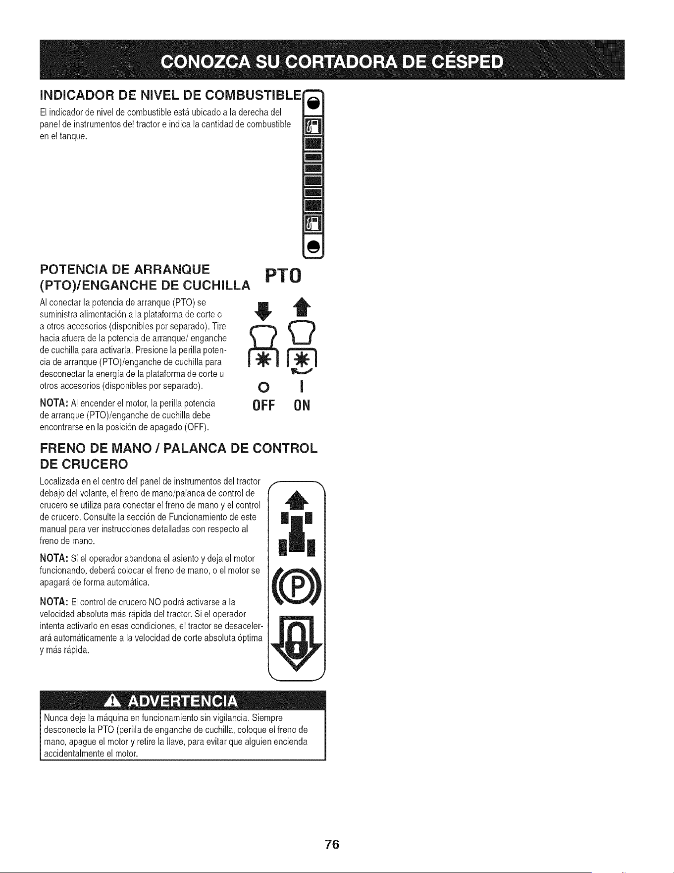
INDICADOR DE NIVEL DE COM
El indicadorde nivelde combustibleestA ubicadoa laderechadel
panelde instrumentosdel tractor e indica la cantidadde combustible
en el tanque.
POTENCIA DE ARRANQUE
(PTO)/ENGANCHE DE CUCHILLA
AIconectar la potenciade arranque(PTO) se
suministraalimentaci6na la plataformade corte o
a otrosaccesorios(disponiblespor separado).Tire
haciaafuerade lapotenciade arranque/enganche
de cuchilla paraactivarla. Presionela perillapoten-
cia de arranque(PTO)/enganchede cuchillapara
desconectarla energiade laplataformade corte u
otrosaccesorios(disponiblespot separado).
NOTA: AI encenderel motor,la perillapotencia
de arranque(PTO)/enganchede cuchilladebe
encontrarseenla posici6nde apagado(OFF).
PTO
OFF 0N
FRENO DE iVlANO / PALANCA DE CONTROL
DE CRUCERO
Localizadaenel centro del panelde instrumentosdeltractor
debajodel volante,el frenode mano/palancade control de
crucerose utilizaparaconectarel freno de manoy el control
de crucero.Consultela secci6nde Funcionamientode este
manualparaver instruccionesdetalladasconrespectoal
frenode mano.
NOTA: Si el operadorabandonael asientoy dejael motor
funcionando,deber_colocar elfreno de mano,o el motorse
apagar_de forma autom_tica.
NOTA: Elcontrol de cruceroNO podr&activarsea la
velocidadabsolutam&sr&pidadel tractor.Si el operador
intentaactivarloen esas condiciones,el tractor se desaceler-
ar_autom_ticamentea la velocidadde corte absoluta6prima
y m_sr_pida.
Nuncadeje la m&quinaen funcionamientosin vigilancia.Siempre
desconectela PTO(perillade enganchede cuchilla,coloqueel frenode
mano,apagueel motory retirela Ilave,paraevitarque alguienencienda
accidentalmenteel motor.
76
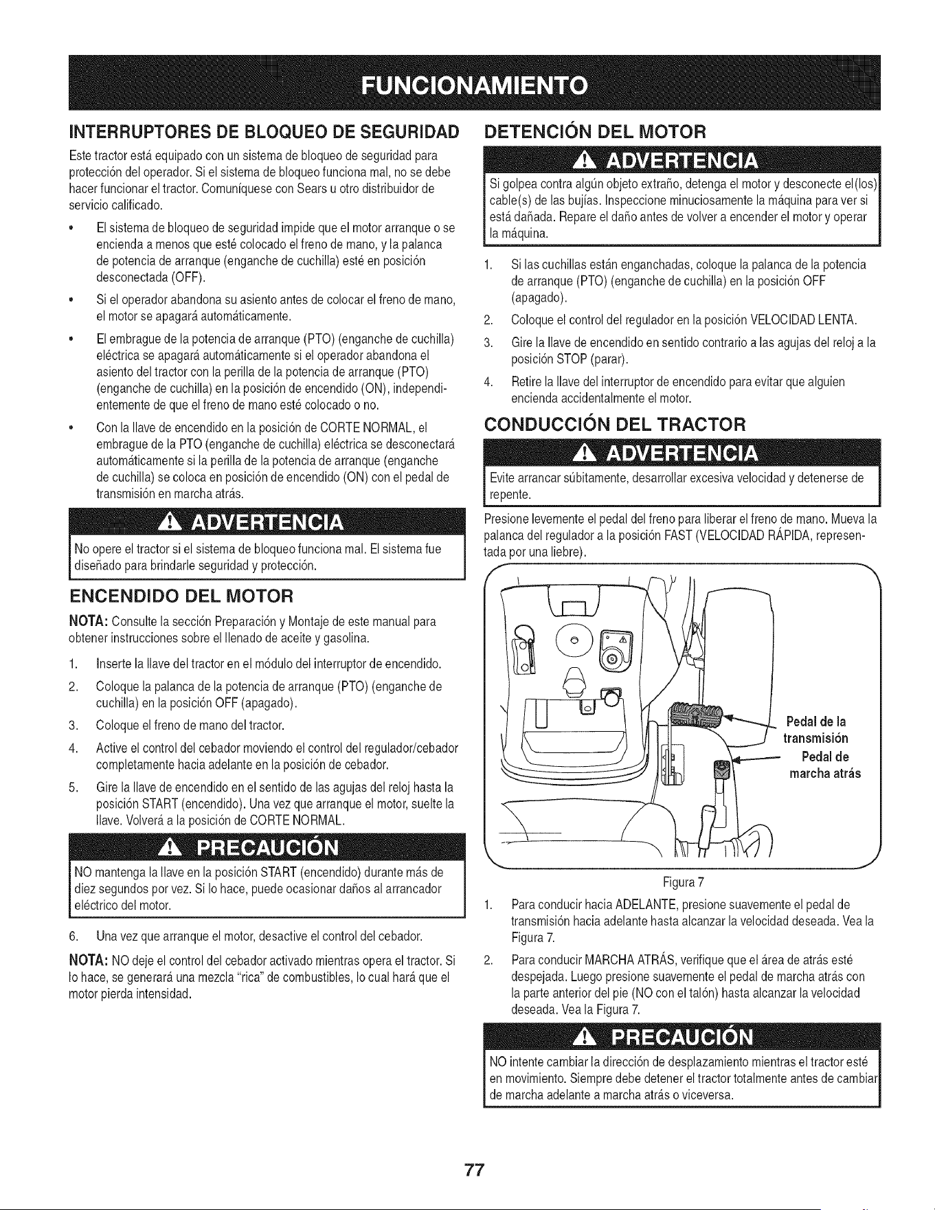
INTERRUPTORESDE BLOQUEO DE SEGURIDAD
Estetractor est_equipadocon un sistemade bloqueode seguridadpara
protecci6ndel operador.Si el sistemade bloqueofunciona mal, no se debe
hacerfuncionar eltractor. Comuniquesecon Sears u otro distribuidorde
serviciocalificado.
• Elsistemade bloqueode seguridadimpidequeel motorarranqueo se
enciendaa menosque estecolocadoel freno de mano,y la palanca
de potenciade arranque(enganchede cuchilla)esteen posici6n
desconectada(OFF).
• Si el operadorabandonasu asientoantesde colocarel frenode mano,
el motorse apagar_autom_ticamente.
• Elembraguede la potenciade arranque(PTO) (enganchede cuchilla)
el@tricase apagar_autom_ticamentesi el operadorabandonael
asientodel tractorcon la perillade la potenciade arranque(PTO)
(enganchede cuchilla)en la posici6nde encendido(ON), independi-
entementede que elfreno de manoeste colocadoo no.
• Con la Ilavedeencendidoen laposici6nde CORTE NORMAL,el
embraguede la PTO(enganchede cuchilla)electricase desconectar_
autom_ticamentesi la perillade la potenciade arranque(enganche
de cuchilla)se colocaen posici6nde encendido(ON) con el pedalde
transmisi6nen marchaarras.
DETENCION DEL MOTOR
e_nder el motoryoperar I
la m_quina.
1. Si las cuchillas est_nenganchadas,coloque la palancade la potencia
de arranque(PTO) (enganchede cuchilla)en la posici6nOFF
(apagado).
2. Coloqueel control del reguladoren la posici6nVELOCIDADLENTA.
3. Girela Ilavede encendidoen sentidocontrario alas agujasdel reloja la
posici6nSTOP(parar).
4. Retirela Ilavedel interruptorde encendidopara evitarquealguien
enciendaaccidentalmenteel motor.
CONDUCCION DEL TRACTOR
EvitearrancarsQbitamente,desarrollarexcesivavelocidady detenersede
repente.
Noopereel tractor si el sistemade bloqueofunciona real.Elsistemafue
dise_adopara brindarle seguridady protecci6n.
ENCENDIDO DEL MOTOR
NOTA: Consultela secci6n Preparaci6ny Montajede estemanualpara
obtenerinstruccionessobre el Ilenadode aceiteygasolina.
1. Insertela Ilavedel tractoren el m6dulodel interruptorde encendido.
2. Coloquela palancade la potenciadearranque (PTO)(enganchede
cuchilla)en la posici6nOFF (apagado).
3. Coloqueel frenode mano deltractor.
4. Activeel control del cebadormoviendoel controldel regulador/cebador
completamentehaciaadelanteen la posici6nde cebador.
5. Girela Ilavede encendidoen elsentido de las agujasdel relojhasta la
posici6nSTART(encendido).Unavez quearranqueel motor,sueltela
Ilave.Volver_a la posici6nde CORTE NORMAL.
NO mantengala Ilaveen la posici6nSTART(encendido)durantem_s de
diez segundospor vez.Si Io hace,puede ocasionardaSosal arrancador
electrico del motor.
6. Unavez quearranqueel motor,desactiveel controldel cebador.
NOTA: NO dejeel controldel cebadoractivadomientrasoperael tractor.Si
Io hace,se generar_una mezcla"rica"de combustibles,Io cual har_ queel
motorpier@ intensidad.
Presionelevementeel pedal delfreno para liberar elfrenode mano.Muevala
palancadel reguladora la posici6nFAST(VELOCIDADR_,PIDA,represen-
tada por unaliebre).
Pedalde la
transmisi6n
Pedalde
marcha arras
Figura7
ParaconducirhaciaADELANTE,presionesuavementeel pedalde
transmisi6nhaciaadelantehastaalcanzarlavelocidaddeseada.Veala
Figura7.
ParaconducirMARCHAATRAS,verifiquequeel _reade arraseste
despejada.Luegopresionesuavementeel pedal de marchaarrascon
laparteanteriordel pie (NO con el tal6n) hastaalcanzarlavelocidad
deseada.Veala Figura7.
NO intentecambiarladirecci6nde desplazamientomientrasel tractor este
en movimiento.Siempredebe detener eltractor totalmenteantesde cambiar
de marchaadelantea marchaarraso viceversa.
77
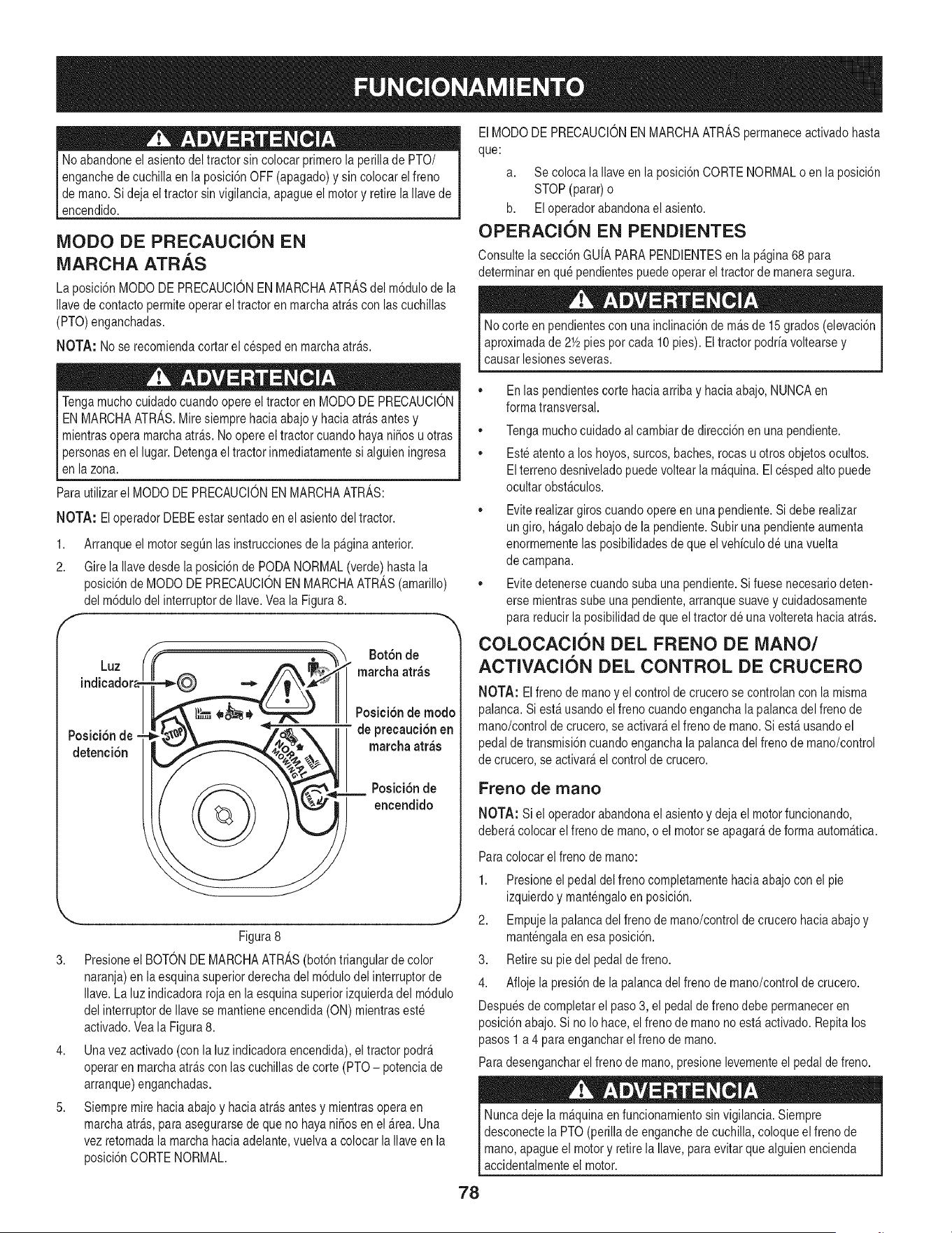
Noabandoneel asientodeltractor sin colocarprimerola perillade PTO/
enganchedecuchillaen la posici6nOFF(apagado)y sin colocar elfreno
de mano.Si deja el tractor sinvigilancia,apagueel motory retirelaIlave de
[ encenddo.
iVlODO DE PRECAUCION EN
MARCHA ATRAS
La posici6nMODO DE PRECAUClONEN MARCHAATRASdel m6dulode la
Ilavede contactopermiteoperarel tractor en marchaarrascon las cuchillas
(PTO)enganchadas.
NOTA: No se recomiendacortarel cesped en marchaarras.
Tengamuchocuidadocuandoopereel tractoren MODODE PRECAUClON
ENMARCHAATRAS.Miresiemprehaciaabajoy haciaatr&santesy
mientrasopera marchaatr&s.Noopereel tractorcuandohayaniSosu otras
personasen el lugar.Detengael tractor inmediatamentesi alguien ingresa
en la zona.
Para utilizarel MODO DE PRECAUClONEN MARCHAATRAS:
NOTA: Eloperador DEBEestar sentadoen elasiento deltractor.
1,
2.
Arranqueel motorsegQnlas instruccionesde la paginaanterior.
Girela Ilavedesde la posici6nde PODANORMAL(verde)hastala
posici6nde MODO DE PRECAUCIONENMARCHAATRAS(amarillo)
del m6dulodel interruptorde Ilave.Vea la Figura8.
Luz
Posici6n de -
detenci6n
Bot6n de
_ marcha atr_s
Posicidnde mode
de precauei6n en
mareha atr_s
Posici6nde
encendido
3,
4,
5,
J
Figura8
Presioneel BOTONDEMARCHAATRAS(bot6ntriangularde color
naranja)en la esquinasuperiorderechadel m6dulodel interruptorde
Ilave.La luzindicadorarojaen la esquinasuperiorizquierdadel m6dulo
del interruptorde Ilavese mantieneencendida (ON)mientraseste
activado.Veala Figura8.
Unavez activado(con la luzindicadoraencendida),eltractor podr&
operaren marchaatr_scon lascuchillasde corte (PTO- potenciade
arranque)enganchadas.
Siempremire haciaabajo y haciaatr_s antesy mientrasoperaen
marchaatr&s,para asegurarsede que no hayaniSosen el&tea. Una
vezretomadala marchahaciaadelante,vuelva a colocar la Ilaveen la
posici6nCORTENORMAL.
ElMODODE PRECAUClONEN MARCHAATRASpermaneceactivadohasta
que:
a. Se colocala Ilaveen la posici6nCORTE NORMALo en la posici6n
STOP (parar)o
b. EIoperadorabandonaelasiento.
OPERACION EN PENDIENTES
Consultela secci6n GUIAPARAPENDIENTESen la p_gina68 para
determinarenque pendientespuedeoperarel tractorde manerasegura.
No corte en pendientescon una inclinaci6ndem&sde 15 grados(elevaci6n
aproximadade 2Y2pies pot cada10 pies). Eltractor podriavoltearsey
causar lesionesseveras.
• Enlas pendientescorte haciaarribay haciaabajo,NUNCAen
formatransversal.
®
®
Tengamuchocuidadoal cambiarde direcci6nen unapendiente.
Esteatentoa los hoyos,surcos,baches,rocas u otrosobjetos ocultos.
Elterrenodesniveladopuedevoltearla m_quina.Elcesped alto puede
ocultar obst_culos.
• Eviterealizargiros cuandoopere en una pendiente.Si debe realizar
un giro,h_galodebajode la pendiente.Subir una pendienteaumenta
enormementelasposibilidadesdeque elvehiculode unavuelta
de campana.
• Evitedetenersecuandosubauna pendiente.Sifuese necesariodeten-
erse mientrassubeuna pendiente,arranquesuavey cuidadosamente
para reducir laposibilidadde que eltractor de unavolteretahacia arras.
COLOCACION DEL FRENO DE NIANO/
ACTIVACION DEL CONTROL DE CRUCERO
NOTA: El frenode manoy el controlde crucerose controlancon la misma
palanca.Si est_ usandoelfrenocuandoengancha lapalanca delfreno de
mano/controlde crucero,se activar&el frenode mano.Si est_ usandoel
pedal de transmisi6ncuandoenganchala palancadel freno de mano/control
de crucero,se activar_el controlde crucero.
Freno de rnano
NOTA: Si el operadorabandonaelasiento y deja el motorfuncionando,
deber_ colocarel frenode mano,o el motorse apagar_de formaautom_tica.
Paracolocarel frenode mano:
1. Presioneel pedaldel freno completamentehaciaabajocon el pie
izquierdoy mantengaloen posici6n.
2. Empujela palancadel frenode mano/controlde crucerohaciaabajoy
mantengalaen esa posici6n.
3. Retiresu pie del pedalde freno.
4. Aflojela presi6nde la palancadel frenode mano/controlde crucero.
Despuesde completarel paso3, el pedalde frenodebe permaneceren
posici6nabajo.Si no Iohace, elfrenode manono est_ activado. Repitalos
pasos 1 a 4 para engancharel frenode mano.
Paradesengancharelfreno de mano,presionelevementeel pedalde freno.
Nuncadeje la m&quinaen funcionamientosinvigilancia. Siempre
desconectela PTO(perilla de enganchede cuchilla, coloqueel frenode
mano,apagueel motory retirela Ilave,paraevitarquealguien encienda
accidentalmenteel motor.
78
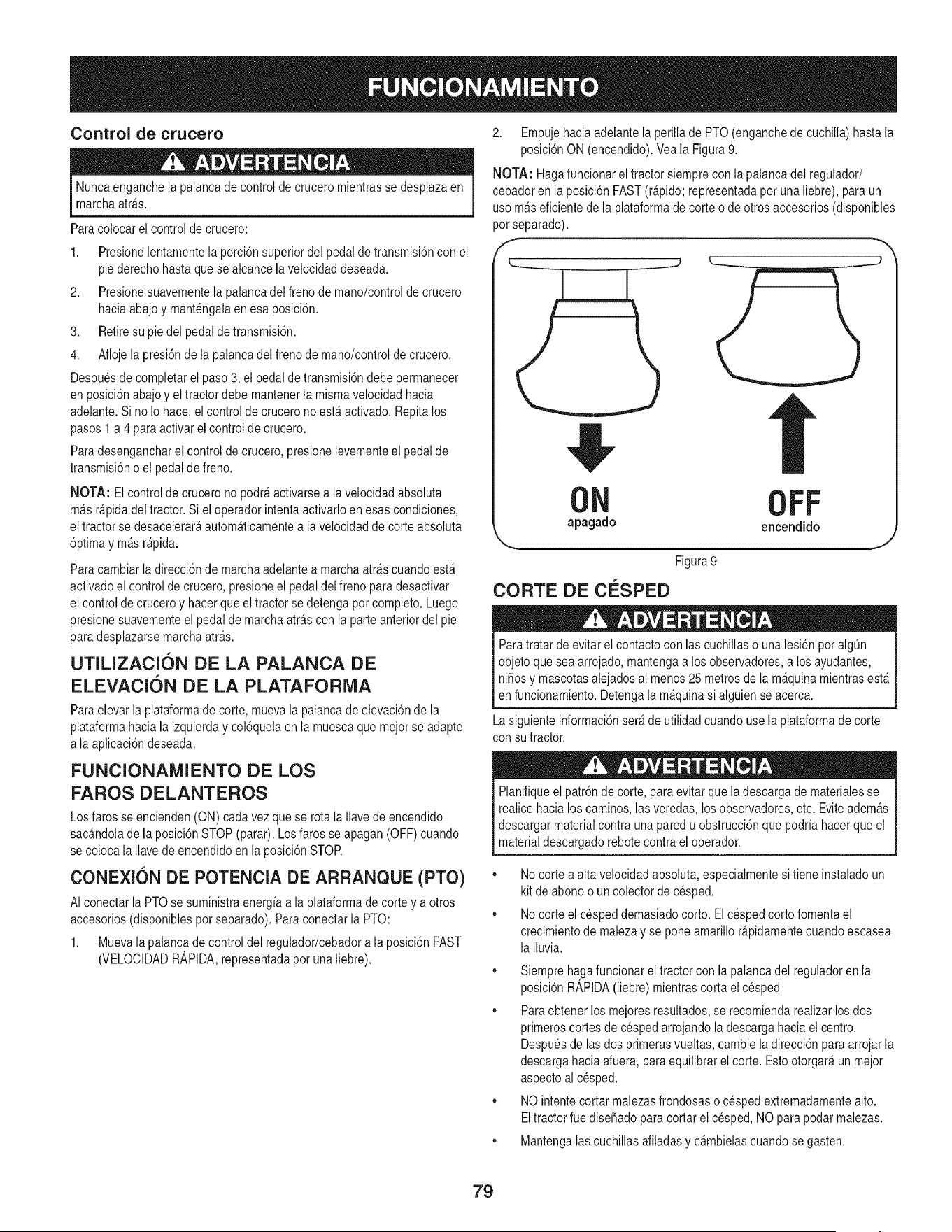
Control de crucero
Nuncaenganchela palancade control de cruceromientrasse desplazaen
marchaarras.
Paracolocar el controlde crucero:
1. Presionelentamentela porci6nsuperiordel pedalde transmisi6ncon el
pie derechohasta quese alcancela velocidaddeseada.
2. Presionesuavementela palancadel frenode mano/controldecrucero
haciaabajoy mantengalaen esa posici6n.
3. Retiresu pie del pedaldetransmisi6n.
4. Aflojela presi6nde la palancadel freno de mano/controlde crucero.
Despuesde completarel paso3, el pedal de transmisi6ndebe permanecer
en posici6nabajoy el tractordebe mantenerla mismavelocidad hacia
adelante.Sino Io hace,elcontrol de crucerono est_activado. Repitalos
pasos1 a 4 paraactivarel controlde crucero.
Paradesengancharel control de crucero,presionelevementeel pedal de
transmisi6no el pedalde freno.
NOTA: El controlde crucerono podr_activarsea lavelocidadabsoluta
m_sr@ida del tractor.Si el operadorintentaactivarloen esas condiciones,
eltractor se desacelerar_autom_ticamentea la velocidadde corte absoluta
6primay m_sr@ida.
Paracambiarla direcci6nde marchaadelantea marchaarrascuandoest_
activadoel controlde crucero,presioneel pedaldel frenopara desactivar
el controlde cruceroy hacerque el tractor se detengapot completo.Luego
presionesuavementeel pedalde marchaarras con la parteanteriordel pie
para desplazarsemarchaarras.
UTILIZACION DE LA PALANCA DE
ELEVACION DE LA PLATAFORiVIA
Paraelevar la plataformade corte, muevala palancade elevaci6ndela
plataformahacia la izquierday col6quelaen la muescaque mejorse adapte
a la aplicaci6ndeseada.
FUNCIONANIIENTO DE LOS
FAROS DELANTEROS
Los faros seencienden(ON) cadavez quese rota la Ilavede encendido
sacandolade la posici6nSTOP (parar).Losfaros se apagan(OFF)cuando
se coloca la Ilavede encendidoen laposici6nSTOR
CONEXION DE POTENCIA DE ARRANQUE (PTO)
AI conectarla PTOse suministraenergiaa la plataformade corte y a otros
accesorios(disponiblespotseparado).Paraconectarla PTO:
1. Muevala palancade controldel regulador/cebadora la posici6nFAST
(VELOCIDADR_,PIDA,representadapot una liebre).
2. Empujehaciaadelantelaperillade PTO(enganchede cuchilla)hasta la
posici6nON (encendido).Veala Figura9.
NOTA: Hagafuncionarel tractor siemprecon la palancadel regulador/
cebadoren la posici6nFAST(r@ido; representadapor una liebre),para un
usom_s eficientede la plataformade corte o de otros accesorios(disponibles
potseparado).
d_5
ON OFF
apagado encendido
Figura9
CORTE DE CESPED
Paratratar de evitarel contactocon lascuchillaso unalesi6n pot algQn
objetoque sea arrojado,mantengaa los observadores,a losayudantes,
ni_osy mascotasalejadosal menos25 metrosde la m&quinamientrasest_
en funcionamiento.Detengala m_quinasi alguiense acerca.
La siguienteinformaci6nser_de utilidadcuando usela plataformade corte
con su tractor.
Planifiqueel patr6ndecorte, paraevitar quela descargade materialesse
realice hacia loscaminos,las veredas,losobservadores,etc. Eviteadem&s
descargarmaterialcontra unaparedu obstrucci6nquepodria hacerque el
materialdescargadorebotecontrael operador.
• Nocorte a alta velocidadabsoluta,especialmentesi tiene instaladoun
kit de abonoo un colectorde cesped.
• Nocorte el cespeddemasiadocorto.Elcespedcorto fomentael
crecimientode malezay se pone amarillor@idamentecuandoescasea
laIluvia.
• Siempre hagafuncionarel tractorcon lapalanca del reguladoren la
posici6nR_,PIDA(liebre) mientrascorta el cesped
• Paraobtener losmejoresresultados,se recomiendarealizar losdos
primeroscortesde cespedarrojandola descargahacia el centro.
Despuesde lasdos primerasvueltas,cambie ladirecci6npara arrojar la
descargahaciaafuera, para equilibrarelcorte. Estootorgar_ un mejor
aspectoal cesped.
• NO intentecortar malezasfrondosaso cesped extremadamentealto.
Eltractor fue diseSadoparacortar el cesped, NO para podar malezas.
• Mantengalascuchillasafiladasy c_mbielascuandosegasten.
79
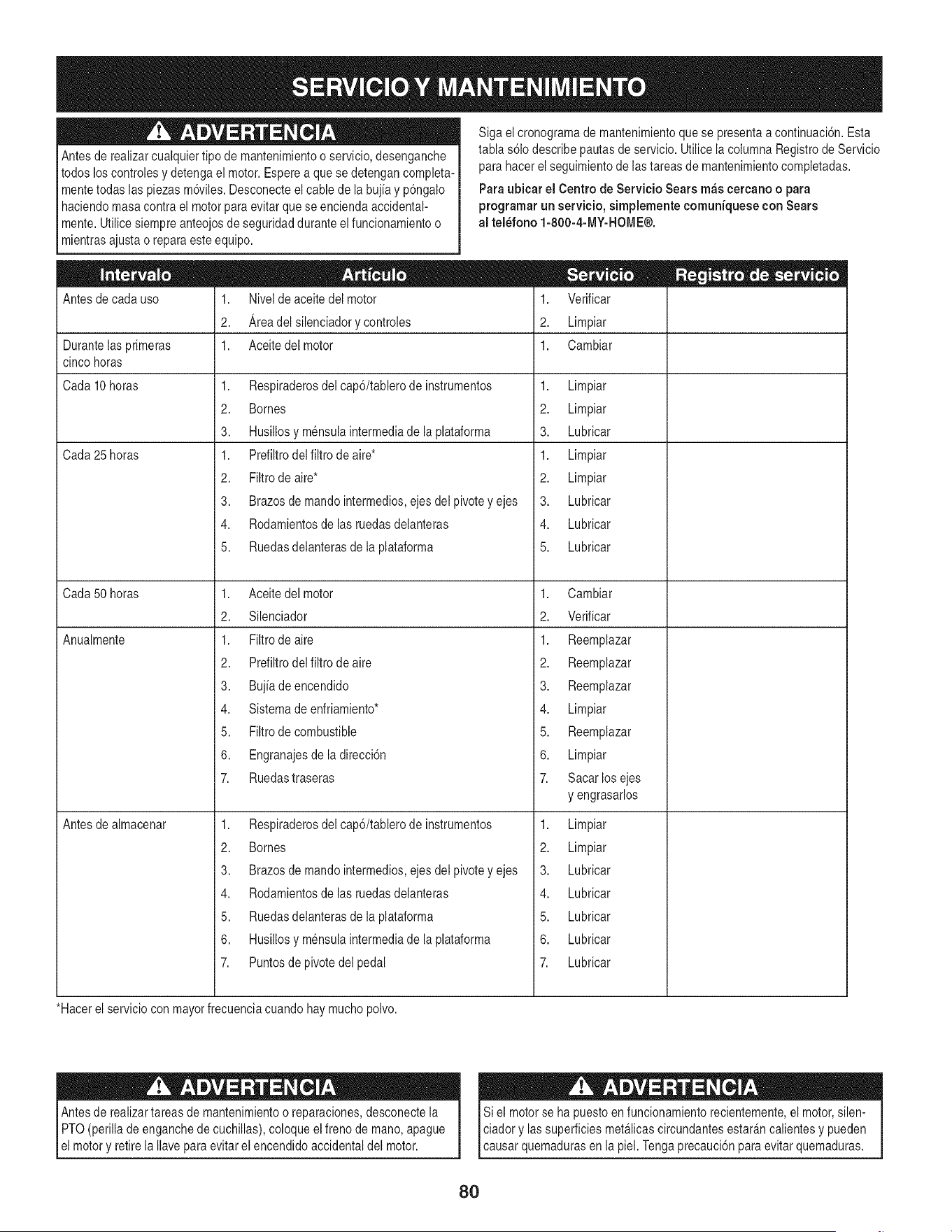
Antesde realizarcualquiertipo de mantenimientoo servicio,desenganche
todos loscontrolesydetengael motor.Esperea que sedetengancompleta-
mentetodas las piezasm6viles.Desconecteel cable de la bujia y p6ngalo
haciendomasacontrael motorpara evitarque seenciendaaccidental-
mente.Utilicesiempreanteojosde seguridadduranteel funcionamientoo
mientrasajustao reparaeste equipo.
Antesde cadauso
Siga elcronogramade mantenimientoquese presentaa continuaci6n.Esta
tabla s61odescribepautasde servicio.Utilice la columnaRegistrodeServicio
para hacerel seguimientode lastareasde mantenimientocompletadas.
Para ubicar ei Centrode ServicioSearsm_s cercanoo para
programarun servicio,simplementeeomuniqueseconSears
al tel_fono 1-800-4-MY-HOME®.
1. Nivelde aceitedel motor
2. Areadel silenciadorycontroles
Durantelasprimeras 1. Aceitedel motor
cinco horas
Cada10 horas
Cada25 horas
Cada50 horas
Anualmente
1. Respiraderosdel cap6/tablero de instrumentos
2. Bornes
3. Husillosy mensulaintermediade la plataforma
1. Prefiltrodel filtro de aire*
2. Filtrode aire*
3. Brazosde mandointermedios,ejes del pivotey ejes
4. Rodamientosde las ruedasdelanteras
5. Ruedasdelanterasde la plataforma
1. Aceitedel motor
2. Silenciador
1. Filtrode aire
2. Prefiltrodel filtro de aire
3. Bujiadeencendido
4. Sistemade enfriamiento*
5. Filtrode combustible
6. Engranajesde la direcci6n
7. Ruedastraseras
1. Respiraderosdel cap6/tablero de instrumentos
2. Bornes
3. Brazosde mandointermedios,ejes del pivotey ejes
4. Rodamientosde las ruedasdelanteras
5. Ruedasdelanterasde la plataforma
6. Husillosy mensulaintermediade la plataforma
7. Puntosde pivotedel pedal
Antesde almacenar
1. Verificar
2. Limpiar
1. Cambiar
1. Limpiar
2. Limpiar
3. Lubricar
1. Limpiar
2. Limpiar
3. Lubricar
4. Lubricar
5. Lubricar
1. Cambiar
2. Verificar
1. Reemplazar
2. Reemplazar
3. Reemplazar
4. Limpiar
5. Reemplazar
6. Limpiar
7. Sacarlosejes
y engrasarlos
1. Limpiar
2. Limpiar
3. Lubricar
4. Lubricar
5. Lubricar
6. Lubricar
7. Lubricar
*Hacerel serviciocon mayorfrecuenciacuandohay muchopolvo.
Antesde realizartareas de mantenimientoo reparaciones,desconectela
PTO(perilla de enganchede cuchillas),coloqueel frenode mano,apague
el motory retirela Ilavepara evitarel encendidoaccidentaldel motor.
Si el motorse ha puestoen funcionamientorecientemente,el motor,silen-
ciador y lassuperficiesmet_licascircundantesestar_ncalientesy pueden
causar quemadurasen la piel. Tengaprecauci6nparaevitarquemaduras.
8O
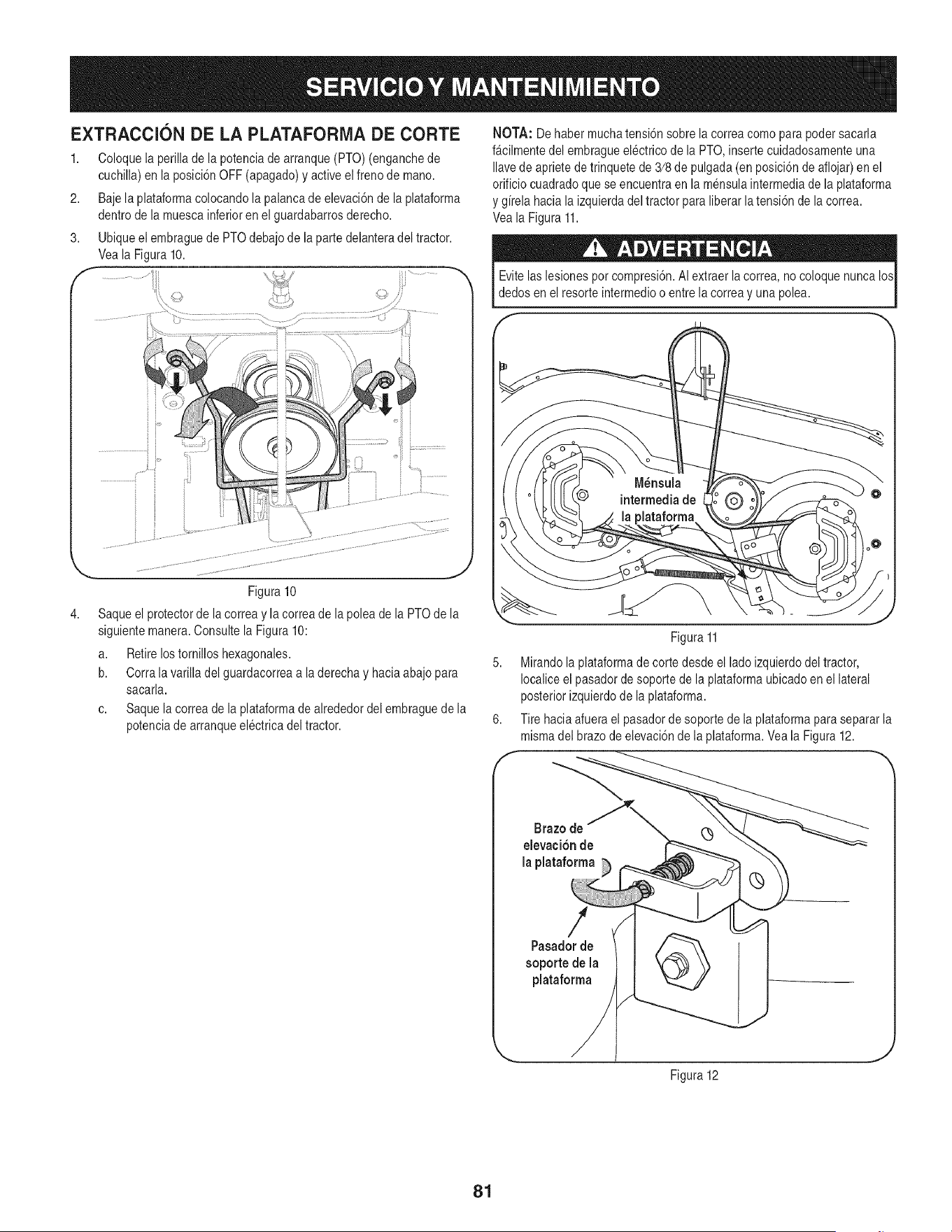
EXTRACCION DE LA PLATAFORIVlA DE CORTE
1. Coloquela perillade la potenciade arranque(PTO) (enganchede
cuchilla)en la posici6nOFF (apagado)y activeel frenode mano.
2. Bajela plataformacolocandola palancade elevaci6nde la plataforma
dentrode la muescainferioren el guardabarrosderecho.
3. Ubiqueelembraguede PTOdebajode la partedelanteradel tractor.
Veala Figura10.
NOTA: Dehaber muchatensi6nsobre la correacomo parapodersacarla
f_cilmentedel embragueelectrico de la PTO,inserte cuidadosamenteuna
Ilavede aprietede trinquetede 3/8de pulgada(en posici6nde aflojar)en el
orificiocuadradoque se encuentraen la mensulaintermediade la plataforma
y girela hacia la izquierdadel tractorpara liberarlatensi6nde la correa.
Veala Figura11.
Evitelas lesionespor compresi6n.AIextraer la correa, no coloquenunca los
dedos en el resorte intermedioo entrela correa y unapolea.
4,
Figura 10
Saqueel protectorde lacorrea y la correade la poleade la PTOde la
siguientemanera.Consultela Figura 10:
a. Retirelostornillos hexagonales.
b. Corralavarilla del guardacorreaa la derechay hacia abajopara
sacarla.
c. Saque lacorrea de la plataformade alrededordel embraguede la
potenciade arranqueelectricadel tractor.
Figura11
5. Mirandola plataformade corte desde el lado izquierdodel tractor,
Iocaliceel pasadorde soportede la plataformaubicadoen el lateral
posteriorizquierdode la plataforma.
6. Tire haciaafuerael pasadorde soportede la plataformapara separarla
mismadel brazode elevaci6nde la plataforma.Veala Figura 12.
Brazo de
elevaci6n de
la plataforma
Pasadorde
soportede la
plataforma
Figura12
81
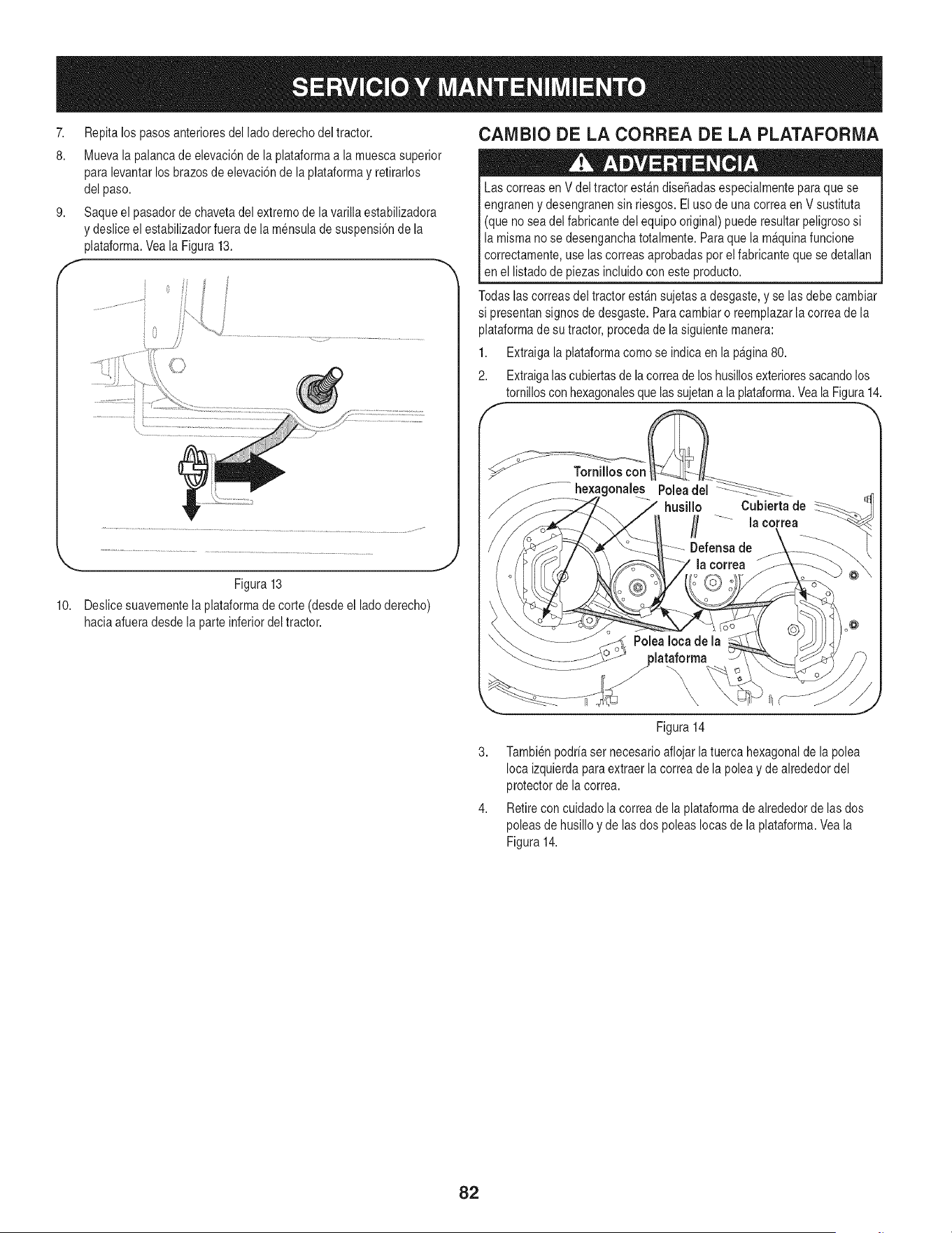
7. Repitalos pasosanterioresdel ladoderechodel tractor.
8. Muevala palancade elevaci6nde la plataformaa la muescasuperior
para levantarlosbrazosde elevaci6nde la plataformay retirarlos
del paso.
9. Saqueel pasadorde chavetadel extremode lavarilla estabilizadora
y desliceel estabilizadorfuerade la mensulade suspensi6nde la
plataforma.Veala Figura13.
10.
_'
Figura 13
Deslicesuavementela plataformade corte (desdeel ladoderecho)
haciaafueradesde la parteinferiordeltractor.
CAMBIO DE LA CORREA DE LA PLATAFORMA
Las correasen V deltractor est_n dise_adasespecialmentepara que se
engraneny desengranensin riesgos.El uso de unacorreaen V sustituta
(que nosea del fabricantedel equipo original)puede resultarpeligrososi
la mismano se desenganchatotalmente.Paraque la m&quinafuncione
correctamente,use lascorreasaprobadaspot el fabricanteque se detallan
en el listadode piezasincluidocon esteproducto.
Todaslascorreasdel tractor est&nsujetasa desgaste,yse las debe cambiar
si presentansignosde desgaste.Paracambiaro reemplazarla correade la
plataformade su tractor,procedade la siguientemanera:
1. Extraigala plataformacomo se indica en la pagina80.
2. Extraigalas cubiertasde lacorreade los husillosexterioressacandolos
tornilloscon hexagonalesque lassujetana laplataforma.Veala Figura14.
Tornilloscon t_
.... he×agonales Poleadel__
husillo Cubierta de
/ la correa
3,
\, r_
J
Figura14
Tambienpodriaser necesarioaflojar latuerca hexagonalde lapolea
Ioca izquierdaparaextraerla correade la poleay de alrededordel
protectorde la correa.
Retirecon cuidado la correade laplataformadealrededorde las dos
poleasde husilloy de lasdos poleas Iocasde laplataforma.Veala
Figura14.
82
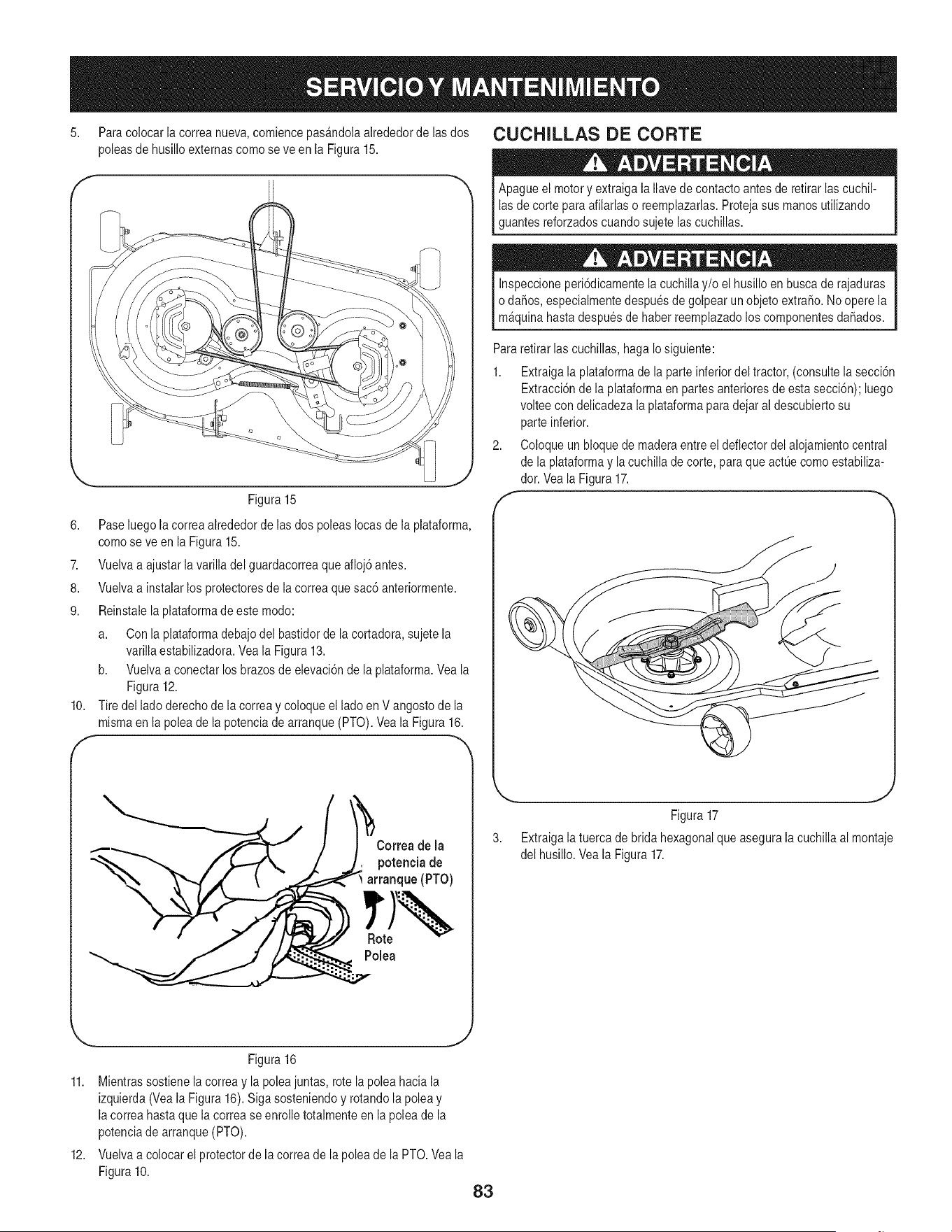
5. Paracolocar la correanueva,comiencepas&ndolaalrededorde lasdos CUCHJLLAS DE CORTE
poleasde husillo externascomo seve en la Figura 15.
Figura 15
6. Paseluegola correaalrededorde lasdos poleasIocasde la plataforma,
comose ve en laFigura 15.
7. Vuelvaa ajustarla varilla del guardacorreaque afloj6 antes.
8. Vuelvaa instalarlos protectoresde lacorrea quesac6 anteriormente.
9. Reinstalela plataformade estemodo:
a. Con la plataformadebajodel bastidorde la cortadora,sujetela
varillaestabilizadora.Veala Figura13.
b. Vuelvaa conectarlosbrazosde elevaci6nde la plataforma.Veala
Figura12.
10. Tire del ladoderechode lacorrea y coloque el lado en V angostode la
mismaen la polea de la potenciade arranque(PTO).Yeala Figura16.
f -
Apagueel motory extraigala Ilavede contactoantes de retirar lascuchil-
las de corte para afilarlaso reemplazarlas.Protejasus manos utilizando
guantesreforzadoscuandosujetelascuchillas.
Inspeccioneperi6dicamentela cuchillay/o el husilloen buscade rajaduras
o daSos,especialmentedespuesde golpearun objetoextraSo.No operela
m_quinahastadespuesde haberreemplazadolos componentesdaSados.
Pararetirar las cuchillas, hagaIo siguiente:
1. Extraigala plataformade la parteinferiordel tractor,(consultela secci6n
Extracci6nde la plataformaen partesanterioresde esta secci6n);luego
volteecon delicadezalaplataformaparadejaral descubiertosu
parteinferior.
2. Coloque un bloquede maderaentreel deflectordel alojamientocentral
de la plataformay lacuchilla de corte, para que actL]ecomoestabiliza-
dor. Vea la Figura17.
Correa de la
potenciade
arranque (PTO)
Polea
Figura17
3. Extraigala tuercade bridahexagonalqueasegurala cuchilla almontaje
del husillo.Veala Figura17.
Figura 16
11. Mientrassostienela correay la poleajuntas,rote la poleahaciala
izquierda(Veala Figura16). Siga sosteniendoy rotandola poleay
la correahastaque la correase enrolletotalmenteen la poleade la
potenciade arranque(PTO).
12. Vuelvaa colocarel protectorde la correade lapolea de la PTO.Veala
Figura10.
83
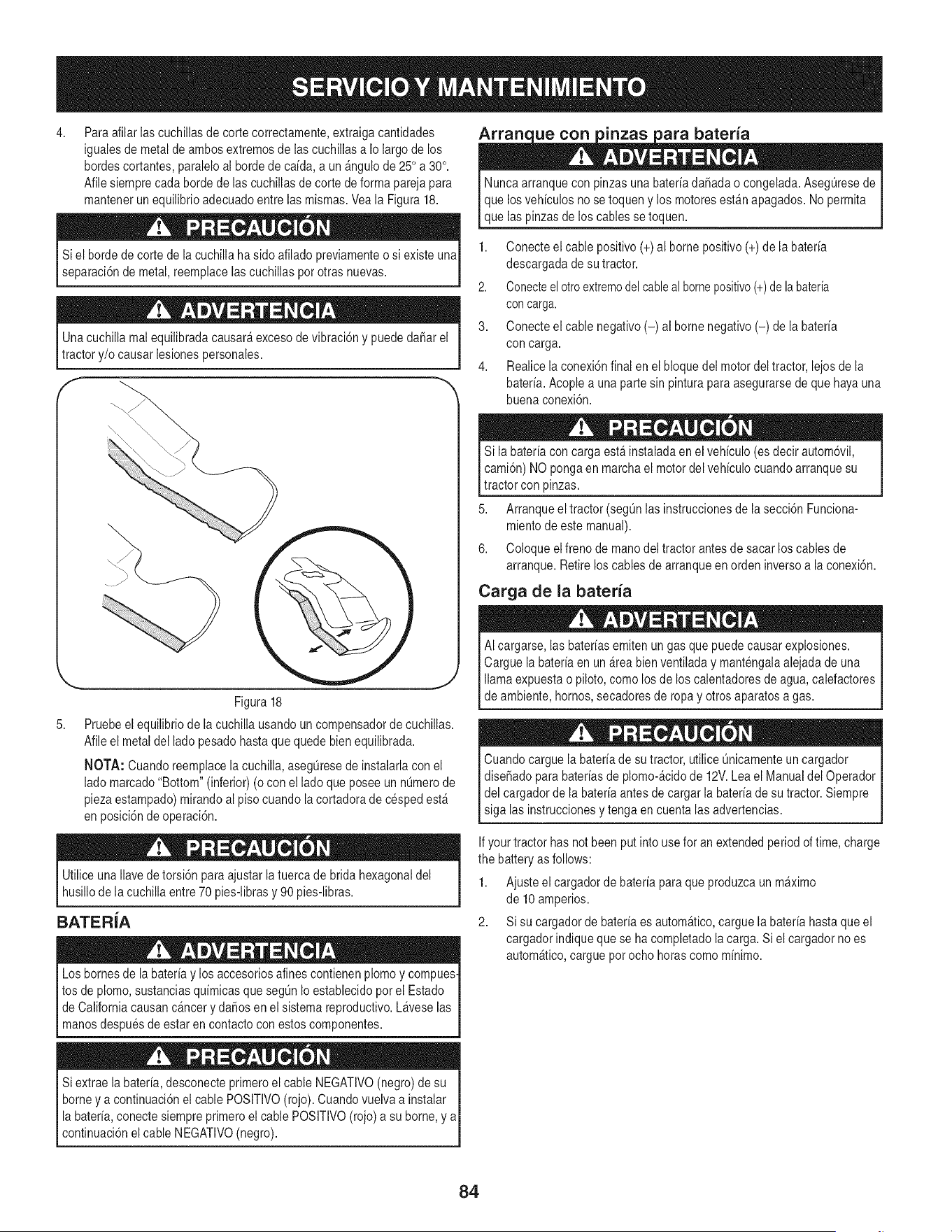
4,
Para afilarlascuchillasde corte correctamente,extraigacantidades
igualesde metalde ambosextremosde lascuchillasa Io largode los
hordescortantes,paraleloal hordede caida, a un _ngulo de 25° a 30°.
Afilesiemprecada hordede las cuchillasde corte de forma parejapara
mantenerun equilibrioadecuadoentrelas mismas.Veala Figura18.
Siel horde de corte de la cuchillaha sido afilado previamenteo si existe una
separaci6nde metal,reemplacelascuchillaspot otras nuevas.
Unacuchilla mal equilibradacausar_excesode vibraci6ny puededa6arel
tractor y/o causar lesiones personales.
5,
J
Figura 18
Pruebeel equilibriode lacuchilla usandoun compensadorde cuchillas.
Afileel metal del ladopesadohastaquequede bien equilibrada.
NOTA: Cuandoreemplacelacuchilla, aseg@esede instalarlacon el
ladomarcado"Bottom" (inferior)(ocon el lado queposee un n0merode
piezaestampado)mirandoal pisocuandola cortadorade cesped est_
en posici6nde operaci6n.
Utiliceuna Ilavede torsi6n para ajustar latuercade brida hexagonaldel
husillode la cuchillaentre70 pies-librasy 90 pies-libras.
BATERIA
Los bornesde la bateriay losaccesoriosalines contienenplomoy compues.
tos de plomo,sustanciasquimicasque segQnIo establecidopor el Estado
I de Californiacausanc_ncer y da_os en el sistemareproductivo.Lavese las
manosdespuesde estar en contactocon estoscomponentes.
Siextrae labateria,desconecteprimeroel cable NEGATIVO(negro)de su
borney a continuaci6nel cablePOSlTIVO(rojo).Cuandovuelva a instalar
la bateria,conectesiempreprimeroel cable POSlTIVO(rojo) a su borne,y aI
_contnuac6n e cab e NEGATVO (negro).
Nuncaarranquecon pinzas una bateriada_adao congelada.AsegQresede
que losvehiculosno se toqueny los motoresest_n apagados.No permita
que laspinzasde loscablessetoquen.
1. Conecteel cable positivo(+)al bornepositivo(+) de la bateria
descargadade su tractor.
2. Conecteelotroextremodelcableal bornepositivo(+)de labateria
concarga.
3. Conecteel cable negativo(-) al borne negativo(-) de la bateria
con carga.
4. Realicelaconexi6nfinal en elbloque del motordel tractor, lejosde la
bateria. Acoplea unapartesin pinturapara asegurarsede que hayauna
buenaconexi6n.
Si la bateriacon carga est_instaladaen el vehiculo(es decirautom6vil,
cami6n)NO pongaen marchael motordelvehiculocuandoarranquesu
tractorcon pinzas.
5. Arranqueel tractor (segQnlasinstruccionesde la secci6nFunciona-
miento de este manual).
6. Coloqueel frenode manodel tractor antesde sacarloscablesde
arranque.Retireloscablesde arranqueen orden inversoa la conexi6n.
Carga de la bateria
AI cargarse,las bateriasemitenun gas quepuedecausarexplosiones.
Carguela bateriaen un _rea bien ventiladay mantengalaalejada de una
llamaexpuestao piloto,como los de los calentadoresde agua,calefactores
de ambiente,hornos,secadoresde ropay otros aparatosa gas.
Cuandocargue la bateriade sutractor, utiliceOnicamenteun cargador
dise_adopara bateriasde plomo-_cidode 12V.Leael Manualdel Operador
del cargadorde labateriaantes de cargarla bateriade su tractor.Siempre
siga las instruccionesy tenga en cuentalas advertencias.
Ifyour tractor has notbeen putinto use for an extendedperiodof time,charge
the batteryas follows:
1. Ajusteel cargadorde bateriapara que produzcaun m_ximo
de 10amperios.
2. Si su cargadorde bateriaes autom_tico,carguela bateriahastaqueel
cargadorindiqueque se ha completadola carga.Siel cargadorno es
autom_tico,carguepot ochohoras como minimo.
84
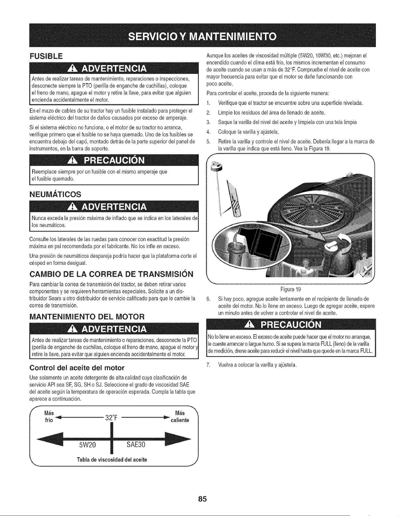
FUSIBLE
Antes de realizartareas de mantenimiento,reparacioneso inspecciones,
desconectesiemprela PTO(perillade enganchede cuchillas),coloque
el freno de mano,apague el motory retire la Wave,para evitarquealguien
enciendaaccidentalmenteel motor.
En el mazode cablesde su tractor hay un fusibleinstaladopara protegerel
sistemaelectricodel tractorde daSoscausadosporexcesode amperaje.
Si el sistemaelectrico no funciona,o el motorde su tractorno arranca,
verifiqueprimeroque el fusibleno se hayaquemado.Uno de losfusibles se
encuentradebajo del cap6, montadodetr_sde la partesuperiordel panelde
instrumentos,en la barra de soporte.
Reemplacesiempreporun fusible con el mismoamperajeque
el fusible quemado.
NEUM.&.TICOS
Nuncaexceda la presi6nm_ximade infladoquese indicaen loslateralesde
losneum_ticos.
Consulteloslateralesde las ruedasparaconocercon exactitud la presiSn
m_ximaen psirecomendadaporel fabricante.No losinfle en exceso.
Una presi6nde neum_ticosdesparejapodriahacer que la plataformacorte el
cespeden formadesigual.
CAMBIO DE LA CORREA DE TRANSMISION
Paracambiarla correade transmisi6ndel tractor,se deben retirarvarios
componentesy se requierenherramientasespeciales.Solicitea un dis-
tribuidorSears u otro distribuidorde servicio calificadopara quele cambie la
correade transmisi6n.
MANTENIMIENTO DEL MOTOR
(perillade enganchede cuchillas,coloqueel frenode mano,apagueel motor
retirela Ilave,para evitarque alguienenciendaaccidentalmenteel motor.
Control del aceite del motor
Usesolamenteun aceitedetergentede alta calidadcuya clasificaci6nde
servicioAPIsea SF,SG, SH o SJ. Seleccioneel grado de viscosidadSAE
del aceitesegQnlatemperaturade operaciSnesperada.Cumplalatabla que
aparecea continuaci6n.
f M_s M_s
frio _ 32°F _'caliente
Aunquelos aceitesde viscosidadmQItiple(5W20, 10W30,etc.) mejoranel
encendidocuandoel climaest_ frio, los mismosincrementanel consumo
de aceitecuandose usan a m_sde 32°F.Compruebeel nivelde aceitecon
mayorfrecuenciaparaevitarqueel motorse daSefuncionandocon
pocoaceite.
Paracontrolarel aceite,procedade la siguientemanera:
1. Verifiquequeel tractorse encuentresobre unasuperficienivelada.
2. Limpielosresiduosdel _rea de Ilenadode aceite.
3. Saquela varilladel niveldel aceitey limpielacon unatela limpia
4. Coloque lavarilla yajQstela.
5. Retirela varilla y controleel nivelde aceite.DeberiaIlegara la marcade
lavarilla queindica queest_ Ileno.Veala Figura19.
Figura 19
6. Si hay poco,agregueaceitelentamenteen el recipientedeIlenadode
aceitedel motor.No Io Ileneen exceso.Luegode agregaraceite,espere
un minutoantesde volvera controlarel nivelde aceite.
NoIoIleneenexceso.Elexcesode aceitepuedehacerqueelmotorno arranque,
lecuestearrancaro larguehumo.Si sesuperalamarcaFULL(lleno)de lavarilla
de medici6n,dreneaceiteparareducirelnivelhastaquequedeen lamarcaFULL.
7. Vuelvaa colocar lavarilla y ajQstela.
Tabla de viscosidad del aceite
J
85
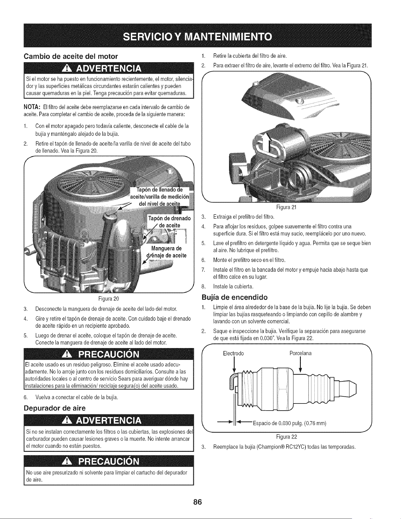
Cambio de aceite del motor
Siel motorse ha puestoenfuncionamientorecientemente,el motor,silencia.
dory lassuperficiesmet_licascircundantesestar_ncalientesy pueden
causarquemadurasen a p e. Tengaprecauc6n paraev tar quemaduras.
NOTA: El filtro delaceitedebereemplazarseen cadaintervalode cambiode
aceite.Paracompletarel cambiode aceite,procedade la siguientemanera:
1. Con el motorapagadoperotodavia caliente,desconecteel cablede la
bujia y mantengaloalejadode labujia.
2. Retireeltap6n de Ilenadode aceite/la varilla de nivel de aceitedel tubo
de Ilenado.Vea la Figura20.
1. Retirelacubiertadel filtro de aire.
2. Paraextract elfiltro de aire,levanteelextremodelfiltro.VealaFigura21.
f -,
Figura20
3. Desconectela manguerade drenajedeaceitedel lado del motor.
4. Girey retireeltap6nde drenajede aceite.Con cuidado baje el drenado
de aceiter_pidoen un recipienteaprobado.
5. Luegode drenarel aceite,coloqueel tap6nde drenajede aceite.
Conectela manguerade drenajedeaceiteal lado del motor.
instalaciones del aceiteusado.
6. Vuelvaa conectarel cable de la bujia.
Depurador de aire
Sino se instalancorrectamentelosfiltroso lascubiertas,las explosionesdel
carburadorpuedencausarlesionesgraveso la muerte.No intentearrancar
el motorcuando no est_npuestos.
Figura21
3. Extraigael prefiltrodel filtro.
4. Paraaflojar losresiduos,golpeesuavementeelfiltro contrauna
superficiedura.Si elfiltro est_ muysucio, reempl_celopot unonuevo.
5. Laveel prefiltroen detergenteliquidoy agua.Permitaquese seque bien
al aire. No lubriqueel prefiltro.
6. Monteel prefiltrosecoen el filtro.
7. Instaleel filtro enla bancadadel motory empujehaciaabajo hastaque
el filtro calce en su lugar.
8. Instalelacubierta.
Bujia de encendido
1. Limpieel _rea alrededorde labasede la buj[a.No lije la buj[a.Se deben
limpiar lasbujias rasqueteandoo limpiandocon cepillodealambrey
lavandocon unsolventecomercial.
2. Saquee inspeccionela bujia.Verifiquelaseparaci6n paraasegurarse
de queest_ fijadaen 0.030".Veala Figura22.
f
Electrodo Porcelana
!
_ "_-_Espacio de 0.030 pulg. (0.76 mm)
gigura 22
3. Reemplace la bujia (Champion® RC12YC)todas las temporadas.
Nouse aire presurizadoni solventeparalimpiarel cartuchodel depurador
de aire.
86
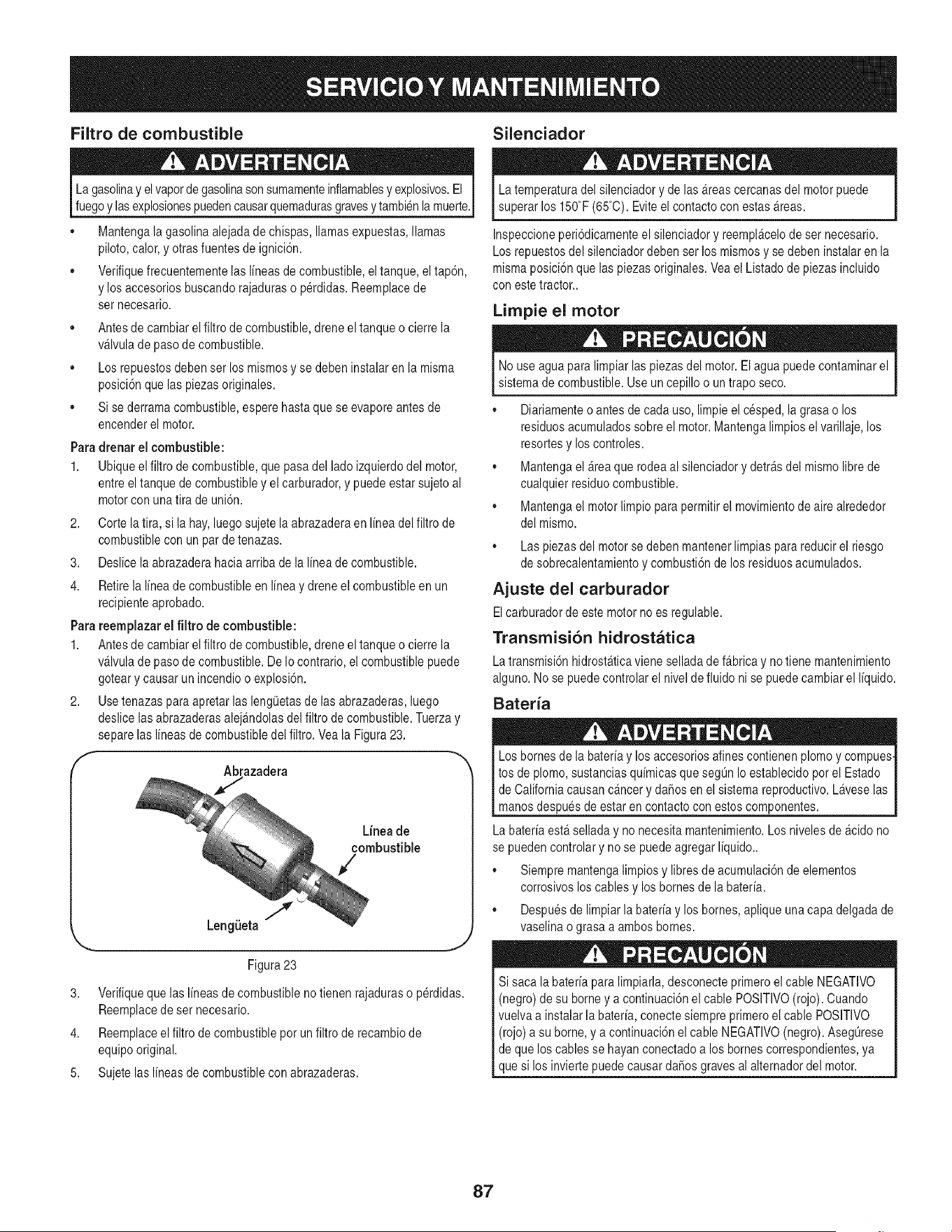
Filtro de combustible Silenciador
La gasolinayelvaporde gasolinason sumamenteinflamablesy explosivos.El
fuegoy lasexplosionespuedencausarquemadurasgravesy tambienlamuerte.
• Mantengala gasolinaalejadade chispas,llamasexpuestas,llamas
piloto,calor,yotras fuentesde ignici6n.
• Verifiquefrecuentementelas I[neasde combustible,el tanque,el tap6n,
y losaccesoriosbuscandorajaduraso p@didas.Reemplacede
set necesario.
• Antesde cambiarel filtro de combustible,dreneel tanqueo cierre la
v_lvulade pasode combustible.
• Los repuestosdebenset los mismosy se debeninstalar en la misma
posici6nquelas piezasoriginales.
• Si sederramacombustible,esperehastaque seevaporeantes de
encenderel motor.
Para drenar el combustible:
1. Ubiqueelfiltro de combustible,quepasadel ladoizquierdodel motor,
entreel tanquede combustibley el carburador,y puedeestar sujetoal
motorcon unatira de uni6n.
2. Corte la tira, si lahay,luegosujetela abrazaderaen I[neadelfiltro de
combustiblecon unparde tenazas.
3. Deslicelaabrazaderahaciaarriba de la I[neade combustible.
4. Retirela I[neade combustibleen I[neay dreneel combustibleen un
recipienteaprobado.
Parareemplazar el filtro de combustible:
1. Antesde cambiarel filtrode combustible,dreneel tanqueo cierre la
v_lvulade pasode combustible.DeIo contrario,el combustiblepuede
goteary causarun incendioo explosi6n.
2. Usetenazas paraapretarlas lengQetasde lasabrazaderas,luego
deslice lasabrazaderasalej_ndolasdel filtro de combustible.Tuerzay
separelas I[neasde combustibledel filtro.Veala Figura23.
f
Abrazadera
3.
4.
5.
Linea de
combustible
Z
Figura23
.J
Verifiqueque lasI[neasde combustibleno tienen rajaduraso p@didas.
Reemplacede ser necesario.
Reemplaceelfiltro de combustiblepot un filtrode recambiode
equipooriginal.
Sujetelas I[neasde combustiblecon abrazaderas.
La temperaturadel silenciadory de las _reascercanasdel motorpuede
superarlos 150°F(65°C).Eviteel contactocon estas_reas.
Inspeccioneperi6dicamenteel silenciadory reempl&celode ser necesario.
Losrepuestosdel silenciadordebenser los mismosy se debeninstalaren la
mismaposici6nque laspiezasoriginales.Veael Listadode piezasincluido
con este tractor..
Limpie el motor
No use agua para limpiarlaspiezas del motor.Elagua puedecontaminarel
sistemade combustible.Use un cepillo o un traposeco.
• Diariamenteo antesde cadauso,limpie el cesped,la grasao los
residuosacumuladossobre el motor.Mantengalimpiosel varillaje,los
resortesy loscontroles.
• Mantengael _reaque rodeaal silenciadory detr_sdel mismolibrede
cualquierresiduocombustible.
• Mantengael motorlimpiopara permitirel movimientode airealrededor
del mismo.
• Las piezasdel motorse debenmantenerlimpias parareducirel riesgo
de sobrecalentamientoy combusti6nde los residuosacumulados.
Ajuste del carburador
Elcarburadorde estemotorno es regulable.
Transmisi6n hidrostatica
Latransmisi6nhidrost&ticavieneselladade f_brica y notiene mantenimiento
alguno.Nose puedecontrolarel nivelde fluidoni se puedecambiarel I[quido.
Bateria
Los bornesde la bater[ay los accesoriosalines contienenplomoy compues
tos de plomo,sustanciasqu[micasqueseg0n Ioestablecidoporel Estado
I de Californiacausanc_ncer y daSosen el sistemareproductivo.Laveselas
[ manos despuesdeestar en contacto con estos componentes.
La bater[aest&selladay no necesitamantenimiento.Los niveles de _cido no
se puedencontrolary no se puedeagregar I[quido..
• Siempre mantengalimpiosy libresde acumulaci6nde elementos
corrosivosloscables y los bornesde la bater[a.
• Despuesde limpiarlabater[ay los homes,apliqueuna capadelgadade
vaselinao grasa a ambos bornes.
Si saca la bater[apara limpiarla,desconecteprimeroel cableNEGATIVO
(negro) de su borney a continuaci6nel cable POSlTIVO(rojo). Cuando
vuelvaa instalarla hater[a,conecte siempreprimeroel cablePOSITIVO
(rojo) a su borne,y a continuaci6nel cable NEGATIVO(negro). Aseg0rese
de que los cablesse hayan conectadoa los bornescorrespondientes,ya
que si los inviertepuedecausardaSosgravesal alternadordel motor.
87
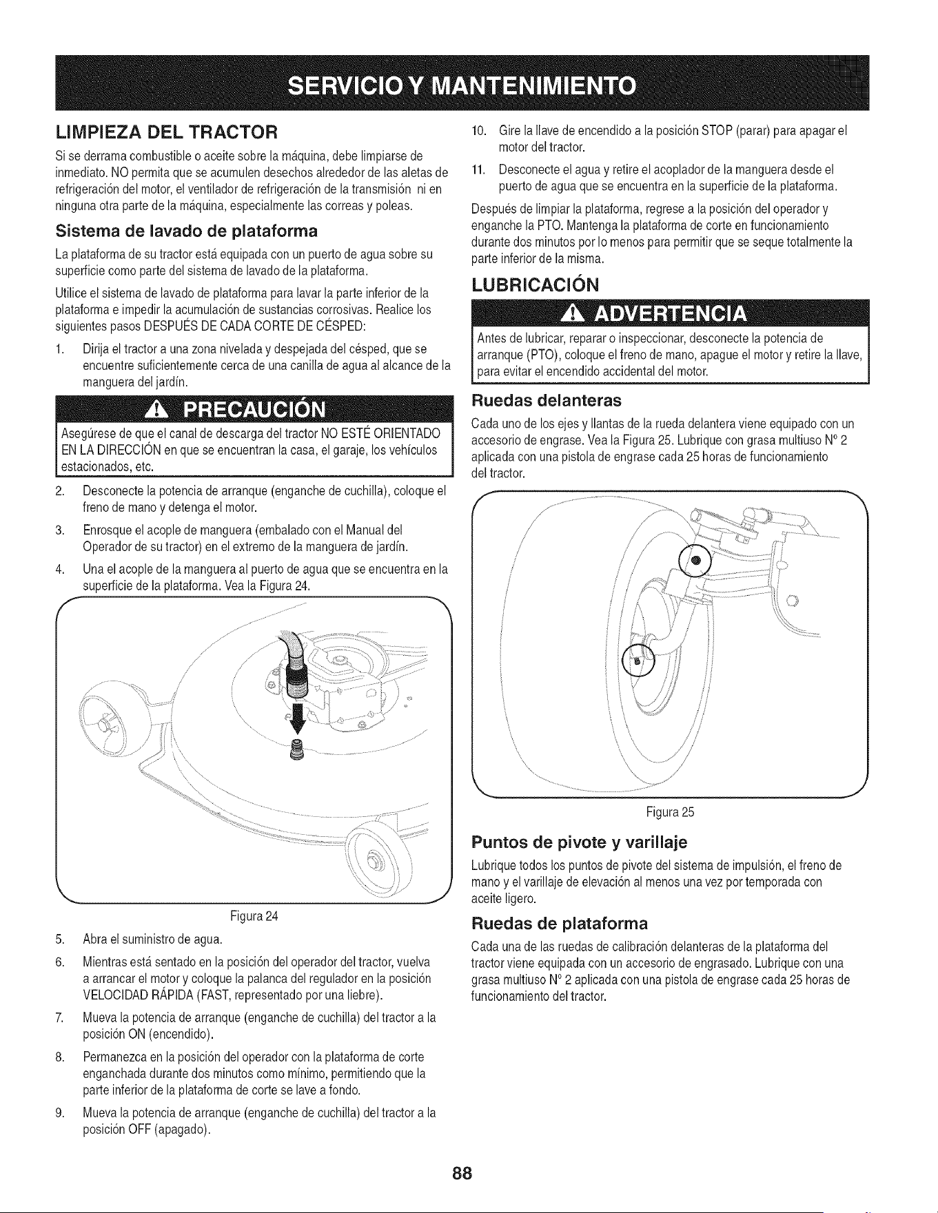
LIIVlPIEZA DEL TRACTOR
Sise derramacombustibleo aceitesobrela m_quina,debe limpiarsede
inmediato.NO permitaquese acumulendesechosalrededordelas aletasde
refrigeraci6ndel motor,el ventiladorde refrigeraci6nde latransmisi6n ni en
ningunaotra partede la m_quina,especialmentelascorreasy poleas.
Sisterna de lavado de plataforrna
La plataformade su tractorest_ equipadacon un puertode aguasobre su
superficiecomo partedel sistemade lavadode la plataforma.
Utiliceel sistemade lavadode plataformaparalavarla parte inferiorde la
plataformae impedirla acumulaci6nde sustanciascorrosivas.Realicelos
siguientespasosDESPUESDECADACORTEDE CESPED:
1. Dirijael tractora unazonaniveladay despejadadel cesped,quese
encuentresuficientementecercade unacanilla de aguaal alcancede la
mangueradeljardin.
AsegQresede queel canal de descargadel tractorNO ESTEORIENTADO
ENLA DIRECCIONen que se encuentranla casa,el garaje,losvehiculos
estacionados,etc.
2. Desconectela potenciade arranque(enganchede cuchilla), coloqueel
frenode manoy detengael motor.
3. Enrosqueel acoplede manguera(embaladocon el Manualdel
Operadorde su tractor)en el extremode lamanguerade jardin.
4. Una elacople de la mangueraal puertode agua quese encuentraen la
superficiede la plataforma.Veala Figura24.
,f
/
Figura24
5. Abraelsuministrode agua.
6. Mientrasest_ sentadoen la posici6ndel operadordel tractor,vuelva
a arrancarel motory coloquela palancadel reguladoren la posici6n
VELOCIDADR_,PIDA(FAST,representadopot una liebre).
7. Muevala potenciade arranque(enganchede cuchilla)del tractora la
posici6nON (encendido).
8. Permanezcaen la posici6ndel operadorcon la plataformade corte
enganchadadurantedos minutoscomo minimo,permitiendoque la
parteinferiorde la plataformadecorte se lavea fondo.
9. Muevala potenciade arranque(enganchede cuchilla)del tractora la
posici6nOFF (apagado).
10. Gire laIlavede encendidoa la posici6nSTOP (parar)para apagarel
motordel tractor.
11. Desconecteel agua y retireel acopladorde la mangueradesde el
puerto de agua quese encuentraen la superficiede la plataforma.
Despuesde limpiar la plataforma,regresea la posici6ndel operadory
enganchela PTO.Mantengala plataformade corte en funcionamiento
durantedos minutospot Io menospara permitirque se sequetotalmentela
parte inferiorde la misma.
LUBRICACION
Antesde lubricar,repararo inspeccionar,desconectela potenciade
arranque(PTO),coloqueel frenode mano,apague el motory retire la Ilave,
para evitarel encendidoaccidentaldel motor.
Ruedas delanteras
Cadauno de los ejesy Ilantasde larueda delanteraviene equipadocon un
accesoriode engrase.Veala Figura25. Lubriquecongrasa multiusoNO2
aplicadacon unapistolade engrasecada 25 horas de funcionamiento
del tractor.
Figura25
Puntos de pivote y varillaje
Lubriquetodos los puntosde pivotedel sistemade impulsi6n,elfrenode
mano y elvarillajede elevaci6nal menosunavez pottemporadacon
aceite ligero.
Ruedas de plataforrna
Cadauna de las ruedasde calibraci6ndelanterasde la plataformadel
tractorviene equipadacon un accesoriode engrasado.Lubriquecon una
grasa multiusoNO2 aplicadacon una pistolade engrasecada25 horasde
funcionamientodel tractor.
88
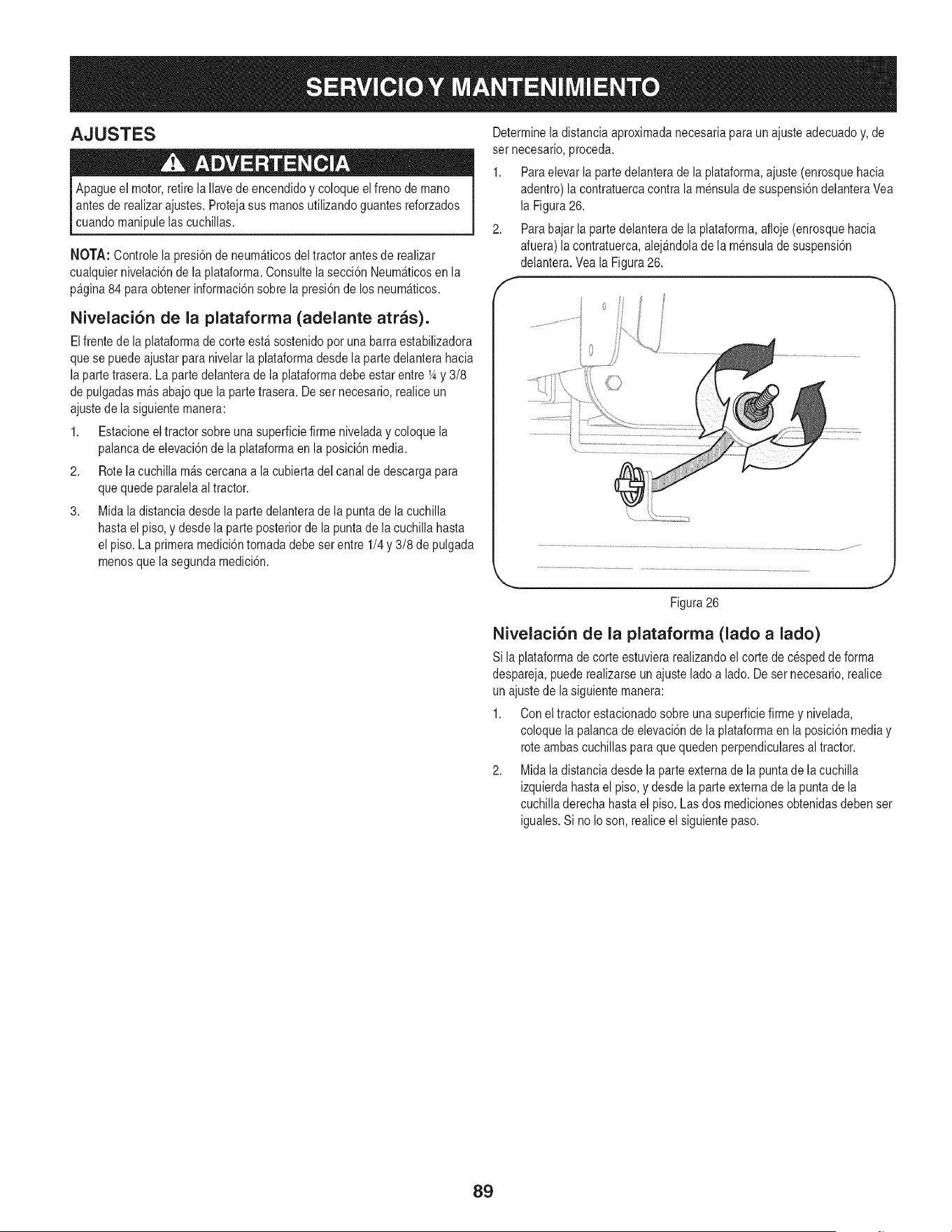
AJUSTES
Apagueel motor,retirela Ilavede encendidoy coloqueelfreno demano
antes de realizar ajustes.Protejasus manosutilizandoguantesreforzados
cuando manipulelas cuchillas.
NOTA: Controlela presi6nde neum_ticosdel tractorantesde realizar
cualquiernivelaci6nde la plataforma.Consultelasecci6n Neum_ticosen la
p&gina84 para obtenerinformaci6nsobre la presi6nde losneum_ticos.
Nivelaci6n de la plataforma (adelante arras).
Elfrentede la plataformade corte est_ sostenidopor unabarra estabilizadora
quese puedeajustar para nivelarla plataformadesde la partedelanterahacia
la partetrasera. La partedelanterade la plataformadebe estar entre1_y 3/8
de pulgadasm&sabajoque la partetrasera.Deset necesario,realiceun
ajustede la siguientemanera:
1. Estacioneeltractor sobre unasuperficiefirme niveladay coloquela
palancade elevaci6nde la plataformaen la posici6nmedia.
2. Rotelacuchilla m&scercanaa la cubiertadel canalde descargapara
quequede paralelaal tractor.
3. Midala distanciadesde laparte delanteradela puntade la cuchilla
hastael piso, ydesde la parteposterior de la puntade la cuchillahasta
el piso. La primeramedici6ntomada debeset entre 1/4 y 3/8 de pulgada
menosque la segundamedici6n.
Determinela distanciaaproximadanecesariapara un ajusteadecuadoy,de
set necesario,proceda.
1. Paraelevarla parte delanterade la plataforma,ajuste (enrosquehacia
adentro) la contratuercacontrala mensulade suspensi6ndelanteraVea
la Figura26.
2. Parabajar la partedelanterade la plataforma,afloje(enrosquehacia
afuera)la contratuerca,alej&ndolade la mensuladesuspensi6n
delantera.Veala Figura26.
f
Figura26
Nivelaci6n de la plataforma (lado a lado)
Si la plataformade corte estuvierarealizandoel corte de cespedde forma
despareja,puede realizarseun ajuste ladoa lado.De set necesario,realice
un ajustede la siguientemanera:
1. Con el tractorestacionadosobreunasuperficiefirme y nivelada,
coloquela palancadeelevaci6nde la plataformaen la posici6nmediay
roteambas cuchillaspara quequedenperpendicularesal tractor.
2. Midaladistanciadesde la parteexternade la puntade lacuchilla
izquierdahastael piso,y desdela parte externade la puntade la
cuchilladerecha hastael piso. Las dos medicionesobtenidasdebenset
iguales.Si no Ioson, realiceel siguientepaso.
89
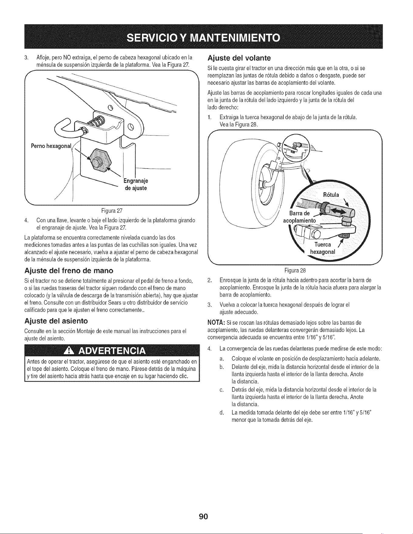
3,
Afloje,pero NO extraiga,el pernode cabeza hexagonalubicadoen la
mensulade suspensi6nizquierdade la plataforma.Yeala Figura27.
Perno hexagonal
Engranaje
de ajuste
Figura27
4. Con unaIlave,levanteo bajeel lado izquierdode la plataformagirando
el engranajede ajuste.Vea la Figura27.
La plataformase encuentracorrectamenteniveladacuandolasdos
medicionestomadasantesalas puntasde lascuchillasson iguales.Unavez
alcanzadoel ajustenecesario,vuelva a ajustarel pernode cabeza hexagonal
de la mensulade suspensi6nizquierdade la plataforma.
Ajuste del freno de mano
Siel tractor no se detienetotalmenteal presionarel pedalde frenoa fondo,
o si las ruedastraserasdel tractor siguenrodandocon elfreno de mano
colocado(y lav&lvulade descargade latransmisi6nabierta),hay queajustar
elfreno. Consultecon un distribuidorSears u otro distribuidorde servicio
calificadoparaque le ajustenel frenocorrectamente..
Ajuste del asiento
Consulteen la secci6nMontajedeeste manuallas instruccionespara el
ajustedel asiento.
Antesde operar eltractor, aseg@esede que el asientoesteenganchadoen
I eltope del asiento.Coloqueel freno de mano.P&resedetr_s de la m&quina
[y tire del asientohaciaarrashastaque encajeen su lugar haciendoclic.
Ajuste del volante
Si le cuestagirar el tractoren unadirecci6n m&squeen la otra, o si se
reemplazanlasjuntasde r6tula debidoa daSoso desgaste,puedeset
necesarioajustarlasbarrasde acoplamientodel volante.
Ajustelas barrasde acoplamientopararoscarlongitudesigualesde cadauna
en lajunta de la r6tula del lado izquierdoy lajuntade la r6tula del
lado derecho:
1. Extraigala tuerca hexagonalde abajode lajunta de la r6tula.
Veala Figura28.
/-
Figura28
2. Enrosquelajuntade la r6tula haciaadentropara acortar la barrade
acoplamiento.Enrosquela juntade la r6tulahaciaafuera paraalargar la
barra de acoplamiento.
3. Vuelvaa colocar latuerca hexagonaldespuesde Iograrel
ajusteadecuado.
NOTA: Si se roscanlasr6tulas demasiadolejossobre las barrasde
acoplamiento,las ruedasdelanterasconverger_ndemasiadolejos. La
convergenciaadecuadase encuentraentre 1/16"y 5/16".
La convergenciade las ruedasdelanteraspuedemedirsedeeste modo:
a. Coloqueel volanteen posici6nde desplazamientohaciaadelante.
b. Delantedel eje, mida ladistancia horizontaldesdeel interiorde la
Ilanta izquierdahastael interiorde laIlantaderecha. Anote
la distancia.
c. Detr_sdel eje, midala distanciahorizontaldesde el interiorde la
Ilanta izquierdahastael interiorde laIlantaderecha. Anote
la distancia.
d. La medidatomadadelantedel eje debe set entre 1/16"y 5/16"
menorque la tomadadetr_sdel eje.
9O
PREPARACI6N DEL MOTOR
IMPORTANTE: Icombustiblequequedaen el tanquecuando hacecalor se
deterioray causaproblemasgravesde encendido.
Nuncaalmacenelatractor corta cespedcon combustibleen el tanque
en unespaciocerradoo en _reas pocoventiladasdondelos gasesdel
combustiblepuedanIlegara unallama expuesta,unachispa o un piloto
como el quetienen algunoshornos,calentadoresde agua,secadoresde
ropao algOnartefactoa gas.
PREPARAClON DEL TRACTOR CORTA
CESPED
Paraevitar quese formendep6sitosde gomadentrodel carburadordel motor
y posiblesdesperfectosen el motor,elsistemade combustibledebe set
vaciadocompletamente,o se debetratar lagasolinacon unestabilizadorpara
evitarel deterioro.
Si utilizaun estabilizadorde combustible:
a. Lea lasinstruccionesy recomendacionesdel fabricante
del producto.
b. Agreguela cantidadcorrectade estabilizadorpara lacapacidad
del sistemade combustiblea gasolinalimpiay nueva.
c. Lleneel tanquecon combustibletratado y hagafuncionarel motor
2-3 minutospara estabilizarel combustibledentrodel carburador.
Cuandovacfeel sistemade combustible:
a. Nodrene elcombustiblecuandoel motorest_ caliente.Permita
queel motorse enfrfebien. Dreneel combustibledentrode un
recipienteaprobadoy al aire libre,lejosde cualquier
llamaexpuesta.
b. Dreneun granvolumende combustibledel tanque,desconectando
la Ifneade combustibledel filtro de combustibleen Ifneaquese
encuentracerca del motor.VeaParadrenarel combustibleen la
pagina86.
La gasolina essumamenteinflamabley puedeset explosivaenciertas
condiciones.Vacfelaantes de almacenarel equipo duranteperfodos
prolongados.Dreneel combustibleOnicamentedentrode un recipiente
aprobadoy alaire libre,lejos de cualquierllamaexpuesta.Dejeque el mo-
tor se enfrfe.Antesde drenarel combustible,apaguecigarrillos,cigarros,
pipasy otrasfuentesde combusti6n.Almacenela gasolinaen un recipiente
aprobado,en un lugarseguro.
c. Vuelvaa conectarla Ifneade combustibley hagafuncionar el
motorhastaque comiencea fallar, useentoncesel cebadorpara
mantenerel motoren marchahastaagotartodo el combustible
del carburador.
d. Desconectela Ifneade combustibley drenela gasolinaque queda
en el sistema.
Limpiey lubriqueperfectamenteeltractor comose describeen las
instruccionesde lubricaci6n.
No utiliceuna lavadoraa presi6no manguerade jardfn para limpiarsu
unidad.
Almacenela unidad en unazona limpiay seca.No la almacenecerca de
productoscorrosivoscomo pot ejemplo fertilizantes.
La gasolinaes unasustanciat6xica.Eliminela gasolinaadecuadamente.
Comunfquesecon lasautoridadeslocalesparaaveriguarcuries son los
metodosadecuadosparaeliminarla gasolina.
Extraigala bujfay vierta una (1)onza de aceitepara motorpor el orificiode
la bujfahaciael interiordel cilindro.Haga girar el motorvariasveces para
distribuirel aceite.Vuelvaa colocar la bujfa.
91
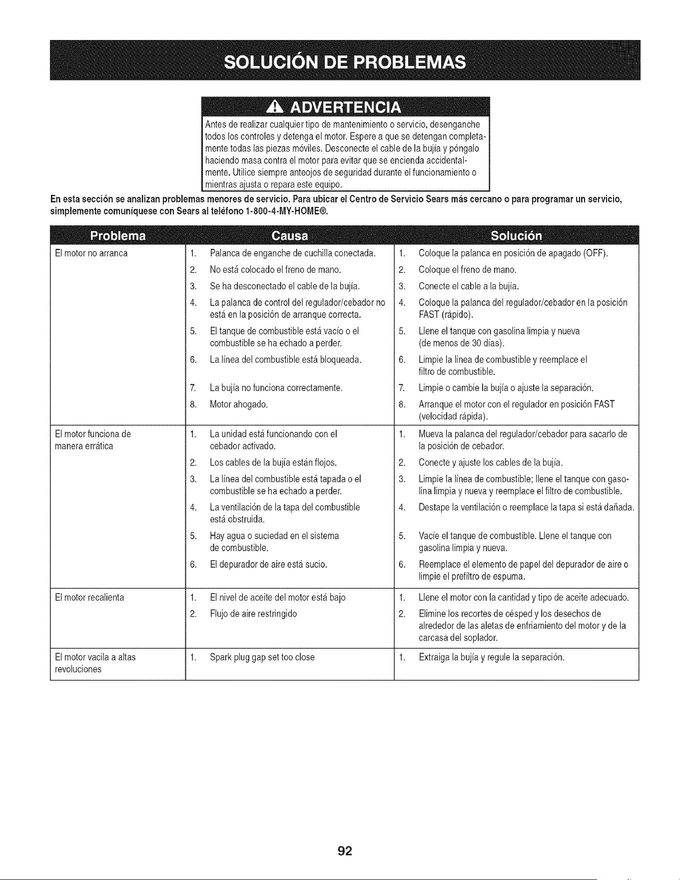
Antesde realizarcualquiertipo de mantenimientoo servicio,desenganche
todos loscontrolesy detengael motor.Esperea que se detengancompleta-
mentetodas laspiezas m6viles.Desconecteel cable de la bujiay p6ngalo
haciendomasacontra el motorparaevitarque se enciendaaccidental-
mente.Utilice siempreanteojosde seguridadduranteelfuncionamientoo
mientrasajustao reparaeste equipo.
En esta secci6n se analizan problemas menores de servicio. Para ubicar el Centro de Servicio Sears m_s eercano o para programarun servicio,
simplementeeomuniquesecon Searsal tel_fono 1-800-4-MY-HOME®.
El motor no arranca 1. Palanca de enganche de cuchilla conectada.
2. No estfi colocado el freno de mano.
3. Se ha desconectado el cable de la bujia.
4. La palanca de control del regulador/cebador no
estfi en laposicidnde arranquecorrect&
5. Eltanquede combustibleestHvacio o el
combustiblese ha echadoa perder.
6. Lalinea del combustibleestHbloqueada.
El motorfuncionade
maneraerrHtica
El motorrecalienta
7. Labujia no funcionacorrectamente.
8. Motorahogado.
1,
2.
3.
4.
5.
6.
LaunidadestHfuncionandocon el
cebadoractivado.
Los cables de la bujia estHnflojos.
La linea del combustibleestHtapadao el
combustiblese ha echadoa perder.
La ventilaci6nde la tapadel combustible
estHobstruida.
Hayaguao suciedaden el sistema
de combustible.
Eldepuradorde aireestHsucio.
1. El nivelde aceitedel motorestHbajo
2. Flujodeairerestringido
1. Coloquela palancaen posici6nde apagado(OFF).
2. Coloqueelfreno de mano.
3. Conecteelcable a la bujia.
4. Coloquela palancadel regulador/cebadoren la posici6n
FAST(rHpido).
5. Lleneel tanquecon gasolinalimpia y nueva
(de menosde 30 dias).
6. Limpiela lineade combustibley reemplaceel
filtro de combustible.
7. Limpieo cambiela bujia o ajustela separaci6n.
8. Arranqueel motorcon el reguladoren posici6nFAST
(velocidadrHpida).
1. Muevala palancadel regulador/cebadorpara sacarlode
la posici6nde cebador.
2. Conectey ajuste loscablesde la bujia.
3. Limpiela lineade combustible;Ileneeltanque con gaso-
linalimpia y nuevay reemplaceelfiltro de combustible.
4. Destapelaventilaci6no reemplacelatapa si estHda_ada.
5. Vacieel tanquede combustible.Lleneel tanquecon
gasolinalimpiay nueva.
6. Reemplaceelelementode papeldel depuradorde aireo
limpieel prefiltrode espuma.
1,
2.
Lleneel motorcon la cantidady tipo de aceiteadecuado.
Eliminelos recortesde cespedy losdesechosde
alrededorde lasaletasde enfriamientodel motory de la
carcasadel soplador.
El motorvacila a altas 1. Sparkpluggap set tooclose 1. Extraigalabujia y regulela separaci6n.
revoluciones
92
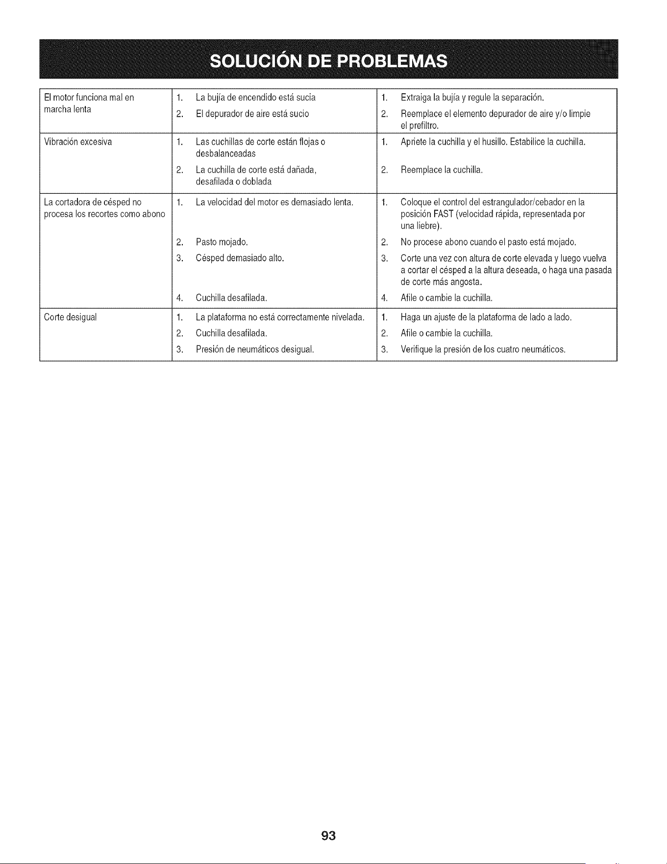
Elmotorfuncionamal en
marchalenta
Vibraci6nexcesiva
La cortadorade cespedno
procesalos recortescomoabono
Cortedesigual
1,
2.
1.
2.
1.
La bujia de encendidoest_ sucia
Eldepuradorde aireest_ sucio
Las cuchillasde corte est_nflojas o
desbalanceadas
La cuchillade corteest_ daSada,
desafiladao doblada
La velocidaddel motores demasiadolenta.
2. Pastomojado.
3. Cespeddemasiadoalto.
4. Cuchilladesafilada.
1. Laplataformano est_correctamentenivelada.
2. Cuchilladesafilada.
3. Presi6nde neum_ticosdesigual.
1. Extraigala bujiay regulela separaci6n.
2. Reemplaceelelementodepuradorde airey/o limpie
el prefiltro.
1. Apriete lacuchillay el husillo. Estabilicela cuchilla.
2. Reemplacelacuchilla.
1. Coloque el controldel estrangulador/cebadorenla
posici6nFAST(velocidadr@ida, representadapot
unaliebre).
2. Noproceseabonocuandoel pastoest_ mojado.
3. Corte unavez con altura de corte elevaday luegovuelva
a cortarel cespeda la alturadeseada,o hagauna pasada
de corte m_s angosta.
4. Afile ocambie la cuchilla.
1. Hagaun ajustede la plataformade ladoa lado.
2. Afile ocambie la cuchilla.
3. Verifiquela presi6nde los cuatroneum_ticos.
93
Felicitacionespor haberrealizadouna adquisici6ninteligente.El
productoCraftsman@queha adquiridoest_dise_adoy fabricado
parabrindarrnuchosa_osde funcionarnientoconfiable.Perocorno
todoslos productosa vecespuederequerirde reparaciones.Esen
esernornentocuandoel disponerde unAcuerdode protecci6npara
reparacionesle puedeahorrardineroy problernas.
A continuaci6nsedetallanlos puntosincluidosenel Acuerdo:
• Servicio experto prestadopor nuestros10,000especialistasen
reparacionesprofesionales
• Servicio ilirnitadosin cargopara laspiezasy la rnanodeobra en
todaslas reparacionescubiertas
• Reernplazodel productohasta 1500d61aressi no es posible
repararel productocubierto
• Descuentode 10%del precionormaldel servicioy delas piezas
relacionadascon el rnisrnoque no est_ncubiertasporel acuerdo;
adern&s,10%del precionormalde la verificaci6nde rnantenirniento
preventivo
• Ayudar_pidapottel_fono- IoIlarnarnosResoluci6nR_pida- el
apoyotelef6nicode unCharnuscaal representante.Pienseen
nosotroscornoel manual"de undue_ohablador."
Unavezadquiridoel Acuerdo,puedeprograrnarel serviciocon
tan s61orealizarunaIlarnadatelef6nica.PuedeIlarnaren cualquier
mornentodeldia o de la nocheo prograrnarun servicioen linea.
ElAcuerdode Protecci6nde Reparaci6nes unacornprasin riesgo.
Siustedanulapor alguna raz6nduranteel periodode garantiade
producto,proporcionarernosun reernbolsoIleno.O,un reernbolso
prorrateadoencualquiermornentodespu_sdelperiodode garantia
de productoexpira,iAdquieraboysu acuerdode protecci6npara
reparaciones!
Seaplican deterrninadaslimitaciones y exclusiones.Paraobtener
inforrnaci6nadicional y preciosen los Estados UnidosIlarne al
1-800-827-6655.
El*Coverage en Canad_variaen algunosarticulos. Paradetalles
Ilenosla IlarnadaCharnuscaCanad_en 1-800-361-6665.
Servicio de instalaci6nde Sears
Sideseasolicitarla instalaci6nprofesionalde Searsde aparatos
dorn_sticos,dispositivosparaabrirportones,calentadoresde agua
y otrosarficulosdorn_sticosirnportantes,en los EstadosUnidoso
Canad_Ilarneal 1-800-4-MY-HOME®.
94
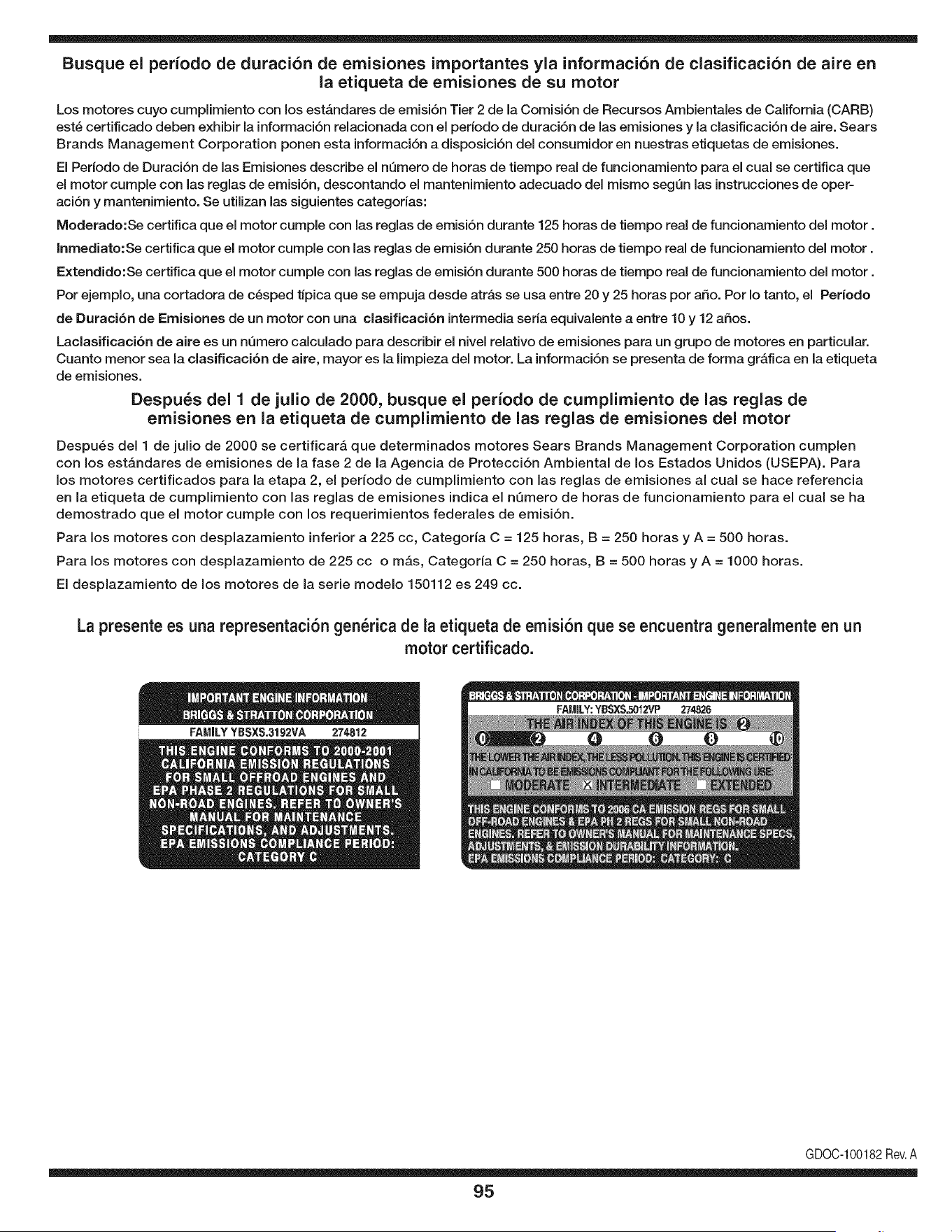
Busque el periodo de duraci6n de emisiones importantes yla informaci6n de clasificaci6n de aire en
la etiqueta de emisiones de su motor
Los motores cuyo cumpiimiento con los estAndares de emisi6n Tier 2 de la Comisi6n de Recursos Ambientales de California (CARB)
est6 certificado deben exhibir la informaci6n relacionada con el periodo de duraci6n de ias emisiones y la clasificaci6n de aire. Sears
Brands Management Corporation ponen esta informaci6n a disposici6n del consumidor en nuestras etiquetas de emisiones.
Ei Periodo de Duraci6n de las Emisiones describe el nQmero de horas de tiempo real de funcionamiento para el cuai se certifica que
el motor cumpie con ias reglas de emisi6n, descontando el mantenimiento adecuado del mismo segQn las instrucciones de oper-
aci6n y mantenimiento. Se utilizan las siguientes categonas:
Moderado:Se certifica que el motor cumpie con las reglas de emisi6n durante 125 horas de tiempo real de funcionamiento del motor.
Inmediato:Se certifica que el motor cumpie con las reglas de emisi6n durante 250 horas de tiempo real de funcionamiento del motor.
Extendido:Se certifica que el motor cumpie con las reglas de emisi6n durante 500 horas de tiempo real de funcionamiento del motor.
Por ejemplo, una cortadora de c6sped tJpica que se empuja desde arras se usa entre 20 y 25 horas por aSo. Por Io tanto, el Periodo
de Duraci6n de Emisiones de un motor con una clasificaci6n intermedia sena equivaiente a entre 10 y 12 aSos.
Laciasificaci6n de aire es un nQmero calculado para describir el nivel relativo de emisiones para un grupo de motores en particular.
Cuanto menor sea la clasificaci6n de aire, mayor es la limpieza del motor. La informaci6n se presenta de forma grAfica en la etiqueta
de emisiones.
Despu_s del 1 de julio de 2000, busque el periodo de cumplimiento de las reglas de
emisiones en la etiqueta de cumplimiento de las reglas de emisiones del motor
Despu6s del 1 de julio de 2000 se certificarA que determinados motores Sears Brands Management Corporation cumplen
con los estAndares de emisiones de la fase 2 de la Agencia de Protecci6n Ambientai de los Estados Unidos (USEPA). Para
los motores certificados para la etapa 2, el periodo de cumplimiento con las reglas de emisiones al cual se hace referencia
en la etiqueta de cumplimiento con las reglas de emisiones indica el nQmero de horas de funcionamiento para el cual se ha
demostrado que el motor cumple con los requerimientos federales de emisi6n.
Para los motores con desplazamiento inferior a 225 cc, Categoria C = 125 horas, B = 250 horas y A = 500 horas.
Para los motores con desplazamiento de 225 cc o mAs, Categoria C = 250 horas, B = 500 horas y A = 1000 horas.
El desplazamiento de los motores de la serie modelo 150112 es 249 cc.
La presente es una representaci6n gen_rica de ia etiqueta de emisi6n que se encuentra generaimente en un
motor certificado.
FAMILYYBSXS.3192VA 274812
GDOC-100182Rev.A
95
(Esta p_.gina se aplica s61oen EE.UU. y Canada.).
Sears Brands Management Corporation, el Consejo de Recursos Ambientales de California (CARB)
y la Agencia de Protecci6n Ambiental de los Estados Unidos (EPA)
Declaraci6n de garantia del sistema de control de emisiones (derechos y obligaciones de la garanfia de defectos del propi=
etario)
LA COBERTURADE LA GARANTJADE CONTROLDEEMISIONESES Y PARALOSMODELOSCERTIFICADOSDELANO 1997Y POSTERIORES,
APLIOABLEA LOSMOTORESCERTIFICADOSCOMPRADOSEN CALIFOR- QUESE COMPRENY UTILICENENCUALQUIERPARTEDE LOS ESTADOS
NIA EN1995Y POSTERIORMENTE,QUESE UTILIZANENCALIFORNIA, UNIDOS(Y A PARTIRDEL 1 DE ENERODE2001 ENCANADA).
Declaraci6n de garanfia sobre defectos en el control de emJsiones para California y los Estados UnJdos
ElConsejode RecursosAmbientalesde California(CARB),la EPA(Agencia
de Protecci6nAmbientalde los EE.UU.)y Searstienenel gusto de explicarla
garantiadel sistemade control de emisionespara motoresdela_o 2000y para
elfuturo con relaci6na motorespeque_ostodo terreno(SORE).En California,
los nuevosmotorespeque_ostodo terrenodebenestar dise_ados,construidos
y equipadosparacumplircon las rigurosasnormasanti-smogdelestado.En
el restode los EstadosUnidos,losmotoresnuevostodoterrenode encendido
porchispacertificadosparael a_o 1997debencumplirest_ndaressimilares
establecidospot la EPA.Sears debegarantizarel sistemade control de emi-
sionesde su motorparalosperiodosde tiempoenumeradosa continuaci6n,
siemprequeno hayaabuso,negligenciao mantenimientoindebidode su
motortodoterrenopeque_o.Su sistemade controlde emisionespuedeincluir
piezastalescomoel carburador,el filtrode aire, elsistemade encendido,el
silenciadoryel conversorcatalitico.Tambienpuedeincluirconectoresy otras
unidadesrelacionadascon las emisiones.Dondeexistaunacondici6ncubierta
por la garantia,Searsreparar_su peque6omotortodo terrenosin costo alguno
incluyendodiagn6stico,piezasy manode obra
Cobertura de la garantJa Sears para defectos en el control de emJsiones
Los motorestodo terrenopeque6osest_ngarantizadosen Io relativoalcontrol a las disposicionesque se indiquena continuaci6n.Si una partede su motor
de emisionesparadefectosenpiezasduranteun periodode dos a_os,sujeto cubiertapot lagaranfiaes defectuosa,Sears reparar_o sustituir_dicha parte.
Responsabilidades del propietario en relacibn con la garantia
Comopropietariodel motortodo terrenopeque_o,Ud.es responsablede la
realizaci6ndel mantenimientorequeridoquese incluyeen las instrucciones
de operaci6ny mantenimiento.Searsrecomiendaquese conserventodoslos
recibosrelativosal mantenimientode su motortodoterrenopeque_o,pero
no pude denegarla garantiasimplementepor la faltade los mismos,o por su
incumplimientodel mantenimientoprogramatic.Comopropietariodel motor
peque_otodoterrenodebe saberque, sinembargo,Sears lepuedenegar
lacoberturade lagarantiasi su motortodoterrenopeque6oouna piezadel
mismohanfalladodebido a abuso,negligencia,mantenimientoindebidoo
a modificacionesno aprobadas.Ud.es responsablede presentarsu motor
todoterrenopeque6oa un distribuidorde serviciosSearsautorizadotan pronto
comoaparezcaun problema.Las reparacionesde la garantiasinconfiicto
debencompletarseen un plazode tiempo razonable,no superiora 30 dias.Si
tienealguna preguntarespectoa sus derechosy responsabilidadesreferentes
a lagarantia,debe contactarcon un representantede serviciosSears al 1--
800--469--4663.La garantiade emisioneses unagarantiapot defectos.Los
defectosse juzgande acuerdocon elfuncionamientonormalde un motor.La
garantiano est_relacionadacon unapruebade emisionesen uso.
Disposiciones de la garantJa Sears para defectos en el control de emJsiones
Las siguientesson disposicionesespecificasrelacionadascon la coberturade lagarantia paradefectosenel controlde emisiones.Esun a_adidoa lagarantiade
motorSearspara motoresno reguladosquese encuentraen lasinstruccionesde funcionamientoy mantenimiento.
1. Piezascon garantia
La coberturade esta garantiase extiendeL]nicamentealas piezas
queaparecena continuaci6n(las partesde lossistemasde control de
emisiones),siempreque dichaspiezasestuvieranya en el motoren el
momentode su compra.
a. Sistemade medici6n de combustible
• Sistema de enriquecimientopara arranqueen frio
• Carburadory partesinternas
• Bombade combustible
b. Sistemade inducci6nde aire
• Filtrode aire
• Colector de admisi6n
c. Sistemadeencendido
• Bujia(s)de encendido
• Sistema de encendidomagneto
d. Sistemadelcatalizador
• Convertidorcatalitico
• Colector de escape
• Sistema de inyecci6nde aireo v_lvulade impulsos
e. Elementosvariadosusadosen lossistemasanteriores
• Wlvulas de vacio,sensiblesa temperatura,posici6ny tiempo
e interruptores
• Conectoresy montajes
2. AIcancede la cobertura
Searsgarantizaal poseedorinicialy a loscompradoressubsiguientes
quelas piezascon garantiano tendr_ndefectosen materialesni mano
de obra que provoquenla falla de las mismasduranteun periodode
dos aSosa partirde la fechaen queel motorse entregaa un comprador
particular.
3. Sin cargo
La reparaci6no reemplazodecualquierpartecon garantia se realizar_
sin cargo alguno parael poseedor,incluyendotareasde diagn6sticoque
permitandeterminarsi una partecon garantiaes defectuosa,siempreque
dichodiagn6sticose realiceen un distribuidorde serviciosSears autoriza-
do. Parael serviciode lagarantia de emisiones,contacteal distribuidorde
serviciosSearsautorizadom_s cercanoincluidoen las"P_ginasamarillas"
en lascategorias"Motores,gasolina","Motoresde gasolina","Podadoras
de cesped",o similares.
4. Reclamacionesy exclusionesa la cobertura
Las reclamacionesde lagarantia debenenviarsede acuerdocon las
disposicionesde la politica de garantia para motoresSears.La cobertura
de lagarantia excluir_defectosen piezascongarantia queno sean partes
originalesSears,o abuso,negligenciao mantenimientoincorrecto,tal y
como seestableceen lapolitica de garantia para motoresSears.Searsno
es responsablede lasfallas en piezascon garantia provocadaspor el uso
de partesa_adidas,que no seanoriginaleso quese hayan modificado.
5. Mantenimiento
Cualquierpartecon garantiaque no esteprogramadaparaset reempla-
zadacomo mantenimientorequerido,o que s61odeba inspeccionarse
regularmentealefecto de "inspeccioneo reemplacesegL]nsea necesario",
estar_garantizadacontradefectosduranteel periodode la garantia.Todas
las piezasgarantizadasqueesten programadaspara su reemplazopara
cumplir con los requisitosde mantenimientoestar_ngarantizadass61o
por el periodoanterior al primerreemplazoprogramaticparadicha pieza.
Cualquierpiezade recambioquesea equivalenteen funcionamientoy
durabilidadpuedeusarse para realizar mantenimientoo reparaciones.El
propietarioes responsablede realizartodoel mantenimientorequerido,tal
y comose define en las instruccionesde funcionamientoy mantenimiento
Sears
6. Coberturaindirecta
Porla presente,la coberturase extiendea la falla de cualquiercomponente
de motorprovocadapot la falla de unapieza con garantiaque este todavia
en periodode garantia.
En los EstadosUnidosy Canad_hay unalinea de atenci6nde 24 horas,1-800-469--4GG3,quecuentacon un menL]con mensajespre-grabadosque contienen
informaci6npara el mantenimientode motores.
DECLARACIONFEDERALy/oDECALIFORNIASOBRE GARANTJAS EN EL CONTROL DE EIVIISIONES
SUS DERECHOS Y OBLIGACIONES EN CUANTO A LA GARANTJA
MTDConsumerGroupInc, laAgencia de Protecci6nMedioambientalde los EstadosUnidos(EPA),y paraaquellosproductoscertificadosparasu ventaen el es-
tadode California,el Departamentode los Recursosdel Aire de California(CARB)secomplacenen explicarla garanfiaque cubre al sistemade control (ECS)de
emisiones(evaporativasy/o de escape)de su equipoy motor(motor de equipos de exteriores)de encendidopot chispaparatodo terreno,peque_o,deexteriores
del a_o2006 y a_osposterioresEn California,losnuevosmotoresde equipos de exterioresdebenestar dise_ados,construidosy equipadospara cumplircon las
estrictasnormasantipoluci6ndel Estado(en otrosestados,losequipos del a_o 1997y modelosposterioresdebenserestar dise_ados,construidosy equipados
para cumplircon las regulacionesde motoresde encendidopor chispa para todoterrenopeque_osde laAgencia de Protecci6nMedioambientalde los Estados
Unidos,(EPA).MTDConsumerGroupInc. debe garantizarel sistemade controlde emisiones(ECS) de su motorde equipos de exteriorespot el periodode
tiempo indicadom_sabajo,siemprey cuando no existauso incorrecto,negligenciao mantenimientoinadecuadode dicho motor.
Su ECSpuedeincluir piezastales como el carburador,el sistemade inyecci6nde combustible,el sistemade encendido,el convertidorcatalitico,losdep6sitos
de combustible,laslineas de combustible,los taponesde combustible,lasv_lvulas,contenedores,filtros, manguerasde vapor,abrazaderas,conectoresy otros
componentesafinesrelacionadoscon lasemisiones.
Dondeexista unacondici6ncubiertapor la garantia, MTDConsumerGroupInc. reparar_su motorde equiposde exterioressincosto alguno incluyendoel
diagn6stico,las piezasy la mano de obra.
COBERTURA DE LA GARANTJA DEL FABRICANTE:
Este sistemade control de emisionesse garantizaporel t@minode dosaSos.Si algunapieza relacionadacon lasemisionesde su motorde equiposde
exterioreses defectuosa,MTDCONSUMERGROUPINC. reparar_o sustituir_dichapieza.
RESPONSABILIDADES DEL PROPIETARIO SEGUN LA GARANTJA:
En su car_cterde propietariodel motorde equipos de exteriores,usted es responsabledel mantenimientorequeridoquese especificaen el manualdel propieta-
rio.MTDConsumerGroupInc le recomiendaque conservetodos losrecibos quecubrenel mantenimientode su motor,no obstanteIo cual MTDConsumerGroup
Inc no podr_denegarel cumplimientode lagarantia Qnicamentepor lafalta de los recibos.
Comopropietariodel motorde equiposde exteriores,usteddebe saberqueMTDConsumerGroupInc. puededenegarlacoberturade lagarantia si su motoro
unapieza del mismofallandebido a uso incorrecto,negligencia,mantenimientoindebidoo a modificacionesno aprobadas.
Ustedes responsablede presentarsu motoral centrode distribuci6no serviciotecnico de MTDConsumerGroupInc. tan prontocomo aparezcael problema.Las
reparacionescubiertaspor la garantiase debenIlevara caboen unlapso razonableque no excedade30 dias. Si tiene alguna preguntarespectode lacobertura
de la garantia, p6ngaseen contactocon el Departamentodel ServicioT@nicode MTDConsumerGroupInc. al telefono1-800-800-7310o pot correoelectr6nico
en http://support.mtdproducts.com
COBERTURA DE LA GARANTJA DE EMISIONES GENERALES:
MTDConsumerGroupIncgarantizaal compradorfinal y a cadacompradorsubsiguienteque el motorde equiposde exteriores:est_ dise_ado,construidoy
equipadode modo de cumplir contodas las regulacionesaplicablesy quese encuentralibre de defectosde materialesy de fabricaci6nque pudierencausarla
falla de una piezagarantizadaidentica,en todos los aspectos materialesa la piezadescriptaen la solicitudde certificaci6nde MTDConsumerGroupInc.
El periodode garantiacomienzaen la fechade entregadel motoral compradorfinal o en lafecha en que la m_quinase pone en funcionamientopot primeravez.
El periodode garantiaes de dosaSos.
Sujetoa ciertas condicionesy exclusionesquese indicana continuaci6n,lagarantia de las piezasrelacionadascon lasemisioneses la siguiente:
1. Cualquierpiezagarantizadaque no este programadaparaser reemplazadacomo partedel mantenimientorequeridoen lasinstruccionesescritassuminis-
tradasse garantizaporel periodo de garantiaarriba mencionado.Si la pieza falla duranteel periodo de coberturade lagarantia, la mismaser_reparada
o reemplazadapor MTDConsumerGroupInc. de acuerdo con el parrafo(4) a continuaci6n.Cualquierpiezareparadao reemplazadasegQnlagaranfia se
garantizar_potel resto del periodode garantia.
2. Cualquierpiezagarantizadaqueeste programadasolamentepara inspecci6nregularen las instruccionesescritassuministradassegarantiza potel periodo
de garantia arribamencionado.Cualquierpiezareparadao reemplazadasegQnla garantiase garantizar_pot el restodel periodo.
3. Cualquierpiezagarantizadaqueeste programadapara reemplazosegQnel mantenimientorequeridode conformidadcon lasinstruccionesescritassuminis-
tradas,se garantizaporel periodode tiempo anteriora laprimerafecha de reemplazoprogramadapara esa pieza.Si la piezafalla antes del primerreemplazo
programado,la mismaser_ reparadao reemplazadapot MTDConsumerGroup Inc. de acuerdo con el parrafo(4) a continuaci6n.Cualquierpiezareparadao
reemplazadabajogarantia se garantizar_potel resto del periodoanterioral primerreemplazoprogramaticpuntualpara esa pieza.
4. La reparaci6no el reemplazode cualquierpieza garantizadade conformidadcon lasdisposicionesde lagarantia queaquise estipulase deben realizaren un
centrode garantiasin costoalgunopara el propietario.
5. Noobstantelas disposicionesque aquise estipulan,losservicios o reparacionesbajo garantiase suministrar_nen todos nuestroscentrosde distribuci6nbajo
franquiciade mantenimientopara los motoreso equiposen cuesti6n.
6. El propietariodel motorde equiposdeexterioresno deber_pagarel trabajode diagn6sticodirectamenteasociadocon unapieza garantizadadefectuosaen
relaci6ncon las emisiones,siemprey cuandodicho trabajode diagn6sticose realiceen un centrocubiertopot la garantia.
7. MTDConsumerGroupInces responsablepotda6os causadosa otros componentesde motoreso equipos derivadosde lafalla bajo garantiade cualquier
piezagarantizada.
8. Durantelatotalidaddelperiododegarantiadelmotoryequipoparatodoterrenoarribamencionado,MTDConsumerGroupIncmantendr_unsuministro
depiezasbajogarantiasuficienteparasatisfacerlademandaesperadadetalespiezas.
9. Cualquierpiezadereemplazosepodr_usarparaelcumplimientodelmantenimientoolasreparacionesbajogarantiaysesuministrar_nsincargopara
elpropietario.Dichousonoreducir_lasobligacionesdegarantiadeMTDConsumerGroupInc.
10.Nosepodr_nusarpiezasadicionalesnimodificadasquenoestenexentasdeacuerdoconelDepartamentodelosRecursosdelAire(AirResourcesBoard).
Elusodecualquierpiezaadicionalomodificadanoexentaporelcompradorfinalser_causaldeinvalidezdelosreclamosbajogaranfia.MTDConsumer
GroupIncnotendr_responsabilidadpotlagarantiadefallasdepiezasgarantizadasquefuerencausadaspotelusodeunapiezaadicionalnoexenta
omodificada.
PIEZAS GARANTIZADAS:
La reparaci6no el reemplazode cualquierpieza garantizadaquede otto modo pudieseestar cubiertapot lagarantia podr_set excluidade tal coberturade
garantiasi MTDConsumerGroupIncdemuestraqueel motores objeto de uso incorrecto,negligenciao mantenimientoinadecuado,y que tal uso incorrecto,
negligenciao mantenimientoinadecuadofue causadirectade la necesidadde reparaci6no reemplazode dicha pieza.NoobstanteIo antedicho,cualquierajuste
de un componentecon un dispositivode limitaci6nde ajusteinstaladoen f_brica y quefuncione adecuadamente,podr_set cubiertopot la garantia.Adem_s,
la coberturabajoestagarantiase extiendesolo a piezasqueestuvieronpresentesen el motory equipotodo terrenoadquiridos.
Est_ncubiertaslas siguientespiezascon garanfia para emisiones(decorresponder):
(1) Sistemade medici6nde combustible
• Sistemade mejoraparainicioen frio (cebadosuave)
• Carburadory piezasinternas(o sistemade inyecci6npotcombustible)
• Bombade combustible
• Dep6sitode combustible
(2) Sistemade inducci6nde aire
• Purificadordeaire
• Colectordeadmisi6n
(3) Sistemade encendido
• Bujia(s) deencendido
• Sistemade encendidopot magneto
(4) Sistemade encendido
• Convertidorcatalitico
• SAl(v_lvula Reed)
(5) Componentesvariosutilizadosen el sistemaanterior
• Wlvulas e interruptoresde vacio,temperatura,posici6nsensiblesal tiempo
• Conectoresy montajes
(6) Controlevaporativo
• Manguerade combustible
• Abrazaderasde la manguerade combustible
• Tap6ndel combustibleatado pot correa
• Cajadecarbono
• Lineas de vapor
GDOC-100223

99

Riding Equipment
questions or problems?
Satisfaction with your purchase
is our number one concern!
To troubleshoot problems,
get answers to questions, order parts,
or schedule repair service for your
Riding Equipment, call the number below.
Para respuestas a preguntas o problemas,
y ordenar piezas o pedir servicio para la
reparacibn de su equipo, Ilame el nt_mero abajo.
1-800-659-5917
Craftsman Help Line
www.craftsman.com
® Registered Trademark / TMTrademark of KCD IP, LLC in the United States, or Sears Brands, LLC in other countries
® Marca Registrada / TMMarca de Fabrica de KCD IP, LLC en Estados Unidos, o Sears Brands, LLC in otros paises


