OPERATOR'S MANUAL
MANUAL DEL OPERADOR
I:RRFISMRN
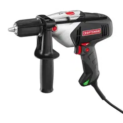
1/2 in. 19.2 VOLT HAMMER DRILL
VARIABLE SPEED
TALADRO DE PERCUSION DE 1/2 pulg. (13 mm), 19,2 V
VELOCIDAD VARIABLE
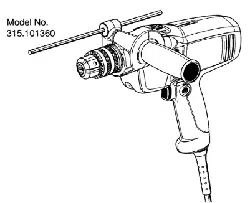
Model No.
315.HD2000
NQmero de modelo
315.HD2000
_, WARNING: To reduce the risk of injury,
the user must read and understand the
operator's manual before using this
product.
A
AlL ADVERTENCIA: Para reducir el riesgo
de lesiones, el usuario debe leer y com-
prender el manual del operador antes de
usar este producto.
BATTERIES AND CHARGERS
SOLD SEPARATELY
LAS BATERiAS Y LOS CARGADORES
SE VENDEN POR SEPARADO
Customer Help Line: 1-800-932-3188
Tel_fono de atenci6n al consumidor: 1-800-932-3188
Sears Brands Management Corporation, 3333 Beverly Rd., Hoffman Estates, IL 60179 USA
Visit the Craftsman web page: www.sears.com/craftsman
Visite etsitio web de Craftsman: www.sears.com/craftsman
990000594
5-28-13 (REV:02)
Save this manual for future reference
Guarde este manual para futuras consulta
0Qus
ENGLISH
• Warranty ...................................................................... 2
• Introduction ................................................................. 2
• General Power Tool Safety Warnings ..................... 3-4
• Hammer Drill Safety Warnings .................................... 4
• Symbols ...................................................................... 5
• Features ...................................................................... 6
• Assembly .................................................................... 7
• Operation .............................................................. 7-10
• Maintenance ............................................................. 11
• Illustrated Parts List .................................................. 12
• Figure numbers (illustrations) ................................... i-iii
• Parts Ordering / Service .............................. Back Page
ESPANOL
• Garantfa ...................................................................... 2
• Introducci6n ................................................................ 2
• Advertencias de seguridad para herramientas
el_ctricas ................................................................. 3-4
• Advertencias de seguridad taladro de percusi6n ....... 5
• Sfmbolos ..................................................................... 6
• Caracterfsticas ............................................................ 7
• Armado ....................................................................... 8
• Funcionamiento .................................................... 8-11
• Mantenimiento .......................................................... 12
• Figura numeras (ilustraciones) ................................. i-iii
• Pedidos de piezas / Servicio ................. Pag. posterior
CRAFTSMAN ®ONE YEAR LIMITED WARRANTY
FOR ONE YEAR from the date of purchase, this product is warranted against any defects in material or workmanship.
With proof of purchase, defective product will be replaced free of charge.
For warranty coverage details to obtain free replacement, visit the web site: www.craftsman.com
This warranty does not cover the bits, which are expendable parts that can wear out from normal use within the warranty
period.
This warranty is void if this product is ever used while providing commercial services or if rented to another person.
This warranty gives you specific legal rights, and you may also have other rights which vary from state to state.
Sears Brands Management Corporation, Hoffman Estates, IL 60179
GARANTiA LIMITADA DE CRAFTSMAN POR UN ANO
Este producto tiene garantfa por cualquier defecto en material o mano de obra DURANTE UN ANO desde la fecha de
compra. Los productos defectuosos se remplazaran sin cargo si presenta un comprobante de pago.
Si desea conocer los detalles de la cobertura de la garantia para conseguir reparaciones o recambios, visite el
sitio Web: www.craftsman.com
Esta garantfa no cubre las brocas, que es una pieza fungible que puede desgastarse por el uso normal durante el
perfodo de garantfa.
La garantfa pierde validez si este producto se utiliza mientras se prestan servicios comerciales o si se alquila a otra per-
sona.
Esta garantfa le otorga derechos legales especfficos y tambi_n puede gozar de otros derechos que varfan segOn el
estado.
Sears Brands Management Corporation, Hoffman Estates, IL 60179
This tool has many features for making its use more pleasant and enjoyable. Safety, performance, and dependability
have been given top priority in the design of this product making it easy to maintain and operate.
Esta herramienta ofrece numerosas caracterfsticas para hacer mas agradable y placentero su uso. En el dise_o de
este producto se ha conferido prioridad a la seguridad, el desempe_o y la fiabilidad, por Io cual se facilita su manejo y
mantenimiento.
2

A
WARNING Read all safety warnings and all
instructions. Failure to follow the warnings and
instructions may result in electric shock, fire and/or
serious injury.
Save all warnings and instructions for future reference.
The term "power tool" in the warnings refers to your
mains-operated (corded) power tool or battery-operated
(cordless) power tool.
WORK AREA SAFETY
• Keep work area clean and well lit. Cluttered or dark
areas invite accidents.
• Do not operate power tools in explosive atmo-
spheres, such as in the presence of flammable liq-
uids, gases or dust. Power tools create sparks which
may ignite the dust or fumes.
• Keep children and bystanders away while operat-
ing a power tool. Distractions can cause you to lose
control.
ELECTRICALSAFETY
• Power tool plugs must match the outlet. Never
modify the plug in any way. Do not use any adapter
plugs with earthed (grounded) power tools. Unmodi-
fied plugs and matching outlets will reduce risk of
electric shock.
• Avoid body contact with earthed or grounded sur-
faces such as pipes, radiators, ranges and refrig-
erators. There is an increased risk of electric shock if
your body is earthed or grounded.
• Do not expose power tools to rain or wet condi-
tions. Water entering a power tool will increase the risk
of electric shock.
• Do not abuse the cord. Never use the cord for car-
rying, pulling or unplugging the power tool. Keep
cord away from heat, oil, sharp edges or moving
parts. Damaged or entangled cords increase the risk of
electric shock.
• When operating a power tool outdoors, use an
extension cord suitable for outdoor use. Use of a
cord suitable for outdoor use reduces the risk of elec-
tric shock.
• If operating a power tool in a damp location is
unavoidable, use a ground fault circuit interrupter
(GFCl) protected supply. Use of a GFCI reduces the
risk of electric shock.
• Use battery only with charger listed. For use with
19.2V nickel-cadmium and 19.2V lithium-ion battery
packs, see tool/appliance/battery pack/charger cor-
relation supplement 988000-272.
PERSONAL SAFETY
• Stay alert, watch what you are doing and use com-
mon sense when operating a power tool. Do not use
a power tool while you are tired or under the influ-
ence of drugs, alcohol or medication. A moment of
inattention while operating power tools may result in
serious personal injury.
• Use personal protective equipment. Always wear
eye protection. Protective equipment such as dust
mask, non-skid safety shoes, hard hat, or hearing
protection used for appropriate conditions will reduce
personal injuries.
• Prevent unintentional starting. Ensure the switch
is in the off-position before connecting to power
source and/or battery pack, picking up or carrying
the tool. Carrying power tools with your finger on the
switch or energising power tools that have the switch
on invites accidents,
• Remove any adjusting key or wrench before turning
the power tool on. A wrench or a key left attached to
a rotating part of the power tool may result in personal
injury.
• Do not overreach. Keep proper footing and balance
at all times. This enables better control of the power
tool in unexpected situations.
• Dress properly. Do not wear loose clothing or jewel-
lery. Keep your hair, clothing and gloves away from
moving parts. Loose clothes, jewellery or long hair can
be caught in moving parts.
• If devices are provided for the connection of dust
extraction and collection facilities, ensure these are
connected and properly used. Use of dust collection
can reduce dust-related hazards.
• Do not wear loose clothing or jewelry. Contain long
hair. Loose clothes, jewelry, or long hair can be drawn
into air vents.
• Do not use on a ladder or unstable support. Stable
footing on a solid surface enables better control of the
power tool in unexpected situations.
POWER TOOL USE AND CARE
• Do not force the power tool. Use the correct power
tool for your application. The correct power tool will
do the job better and safer at the rate for which it was
designed.
• Do not use the power tool if the switch does not
turn it on and off. Any power tool that cannot be
controlled with the switch is dangerous and must be
repaired.
• Disconnect the plug from the power source and/or
the battery pack from the power tool before making
any adjustments, changing accessories, or storing
power tools. Such preventive safety measures reduce
the risk of starting the power tool accidentally.
• Store idle power tools out of the reach of children
and do not allow persons unfamiliar with the power
tool or these instructions to operate the power tool.
Power tools are dangerous in the hands of untrained
users.
• Maintain power tools. Check for misalignment or bind-
ing of moving parts, breakage of parts and any other
3 - English
condition that may affect the power tool's operation.
If damaged, have the power tool repaired before use.
Many accidents are caused by poorly maintained power
tools.
• Keep cutting tools sharp and clean. Properly main-
tained cutting tools with sharp cutting edges are less
likely to bind and are easier to control.
• Use the power tool, accessories and tool bits etc.
in accordance with these instructions, taking into
account the working conditions and the work to be
performed. Use of the power tool for operations different
from those intended could result in a hazardous situation.
BATTERY TOOL USE AND CARE
• Recharge only with the charger specified by the
manufacturer. A charger that is suitable for one type
of battery pack may create a risk of fire when used with
another battery pack.
• Use power tools only with specifically designated bat-
tery packs. Use of any other battery packs may create a
risk of injury and fire.
• When battery pack is not in use, keep it away from
other metal objects, like paper clips, coins, keys, nails,
screws or other small metal objects, that can make a
connection from one terminal to another. Shorting the
battery terminals together may cause burns or a fire.
• Under abusive conditions, liquid may be ejected
from the battery; avoid contact. If contact acciden-
tally occurs, flush with water. If liquid contacts eyes,
additionally seek medical help. Liquid ejected from the
battery may cause irritation or burns.
SERVICE
• Have your power tool serviced by a qualified repair
person using only identical replacement parts. This will
ensure that the safety of the power tool is maintained.
• When servicing a power tool, use only identical
replacement parts. Follow instructions in the Mainte-
nance section of this manual. Use of unauthorized parts
or failure to follow Maintenance instructions may create a
risk of shock or injury.
• Wear ear protectors when impact drilling. Exposure to
noise can cause hearing loss.
• Use auxiliary handle(s), if supplied with the tool. Loss
of control can cause personal injury.
• Hold power tool by insulated gripping surfaces, when
performing an operation where the cutting accessory
may contact hidden wiring. Cutting accessory
contacting a "live" wire may make exposed metal parts
of the power tool "live" and could give the operator an
electric shock.
• Know your power tool. Read operator's manual
carefully. Learn its applications and limitations, as well
as the specific potential hazards related to this power
tool. Following this rule will reduce the risk of electric
shock, fire, or serious injury.
• Always wear eye protection with side shields marked
to comply with ANSI Z87.1 when assembling parts,
operating the tool, or performing maintenance.
Following this rule will reduce the risk of serious personal
injury.
• Protect your lungs. Wear a face or dust mask if the
operation is dusty. Following this rule will reduce the risk
of serious personal injury.
• Protect your hearing. Wear hearing protection during
extended periods of operation. Following this rule will
reduce the risk of serious personal injury.
• Battery tools do not have to be plugged into an
electrical outlet; therefore, they are always in
operating condition. Be aware of possible hazards
when not using your battery tool or when changing
accessories. Following this rule will reduce the risk of
electric shock, fire, or serious personal injury.
• Do not place battery tools or their batteries near fire
or heat. This will reduce the risk of explosion and possibly
injury.
• Do not crush, drop or damage battery pack. Do not
use a battery pack or charger that has been dropped
or received a sharp blow. A damaged battery is subject
to explosion. Properly dispose of a dropped or damaged
battery immediately.
• Batteries can explode in the presence of a source
of ignition, such as a pilot light. To reduce the risk of
serious personal injury, never use any cordless product
in the presence of open flame. An exploded battery can
propel debris and chemicals. If exposed, flush with water
immediately.
• Do not charge battery tool in a damp or wet location.
Following this rule will reduce the risk of electric shock.
• For best results, your battery tool should be charged
in a location where the temperature is more than
50°F but less than 100°F. To reduce the risk of serious
personal injury, do not store outside or in vehicles.
• Under extreme usage or temperature conditions,
battery leakage may occur. If liquid comes in contact
with your skin, wash immediately with soap and water.
If liquid gets into your eyes, flush them with clean
water for at least 10 minutes, then seek immediate
medical attention. Following this rule will reduce the risk
of serious personal injury.
• Save these instructions. Refer to them frequently and
use them to instruct others who may use this tool. If you
loan someone this tool, loan them these instructions also.
4 - English
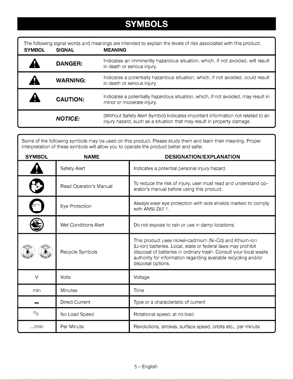
Thefollowingsignalwordsandmeaningsareintendedtoexplainthelevelsofriskassociatedwiththisproduct.
SYMBOL SIGNAL MEANING
,_ DANGER:
Indicates an imminently hazardous situation, which, if not avoided, will result
in death or serious injury.
,_ WARNING:
Indicates a potentially hazardous situation, which, if not avoided, could result
in death or serious injury.
,_ CAUTION:
Indicates a potentially hazardous situation, which, if not avoided, may result in
minor or moderate injury.
NOTICE:
(Without Safety Alert Symbol) Indicates important information not related to an
injury hazard, such as a situation that may result in property damage.
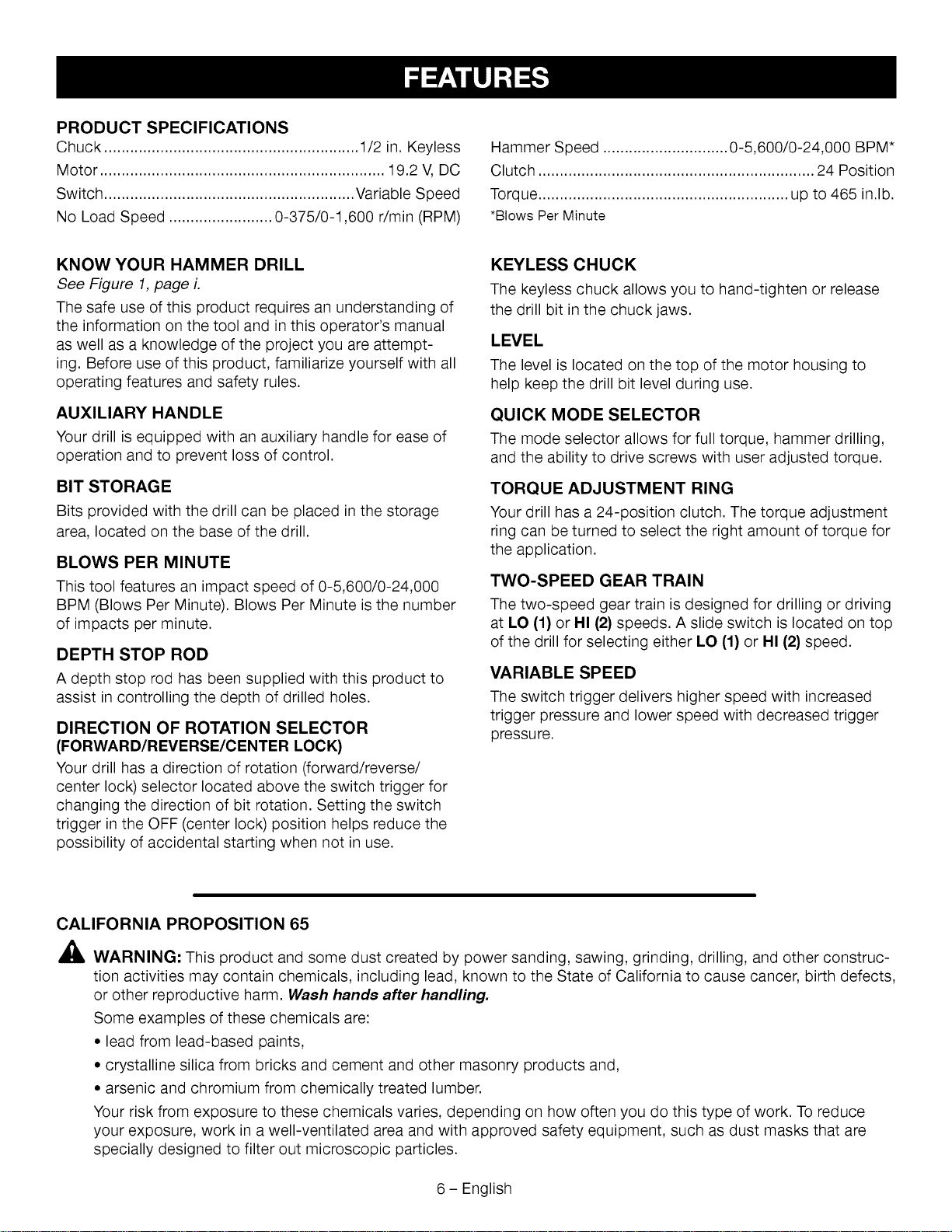
Some of the following symbols may be used on this product. Please study them and learn their meaning. Proper
interpretation of these symbols will allow you to operate the product better and safer.
SYMBOL NAME
A
@
0
@
_._Yc2_ ....
DESIGNATION/EXPLANATION
Safety Alert
Read Operator's Manual
Eye Protection
Wet Conditions Alert
Recycle Symbols
Indicates a potential personal injury hazard.
To reduce the risk of injury, user must read and understand op-
erator's manual before using this product.
Always wear eye protection with side shields marked to comply
with ANSI Z87.1.
Do not expose to rain or use in damp locations.
This product uses nickel-cadmium (Ni-Cd) and lithium-ion
(Li-ion) batteries. Local, state or federal laws may prohibit
disposal of batteries in ordinary trash. Consult your local waste
authority for information regarding available recycling and/or
disposal options.
V Volts Voltage
min Minutes Time
..-, Direct Current Type or a characteristic of current
no No Load Speed Rotational speed, at no load
.../min Per Minute Revolutions, strokes, surface speed, orbits etc., per minute
a
5 - English
PRODUCTSPECIFICATIONS
Chuck ........................................................... 1/2 in. Keyless
Motor .................................................................. 19.2 V, DC
Switch .......................................................... Variable Speed
No Load Speed ........................ 0-375/0-1,600 r/min (RPM)
Hammer Speed ............................. 0-5,600/0-24,000 BPM*
Clutch ................................................................ 24 Position
Torque .......................................................... up to 465 in.lb.
*Blows Per Minute
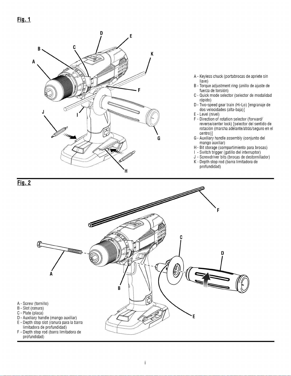
KNOW YOUR HAMMER DRILL
See Figure 1, page L
The safe use of this product requires an understanding of
the information on the tool and in this operator's manual
as well as a knowledge of the project you are attempt-
ing. Before use of this product, familiarize yourself with all
operating features and safety rules.
AUXILIARY HANDLE
Your drill is equipped with an auxiliary handle for ease of
operation and to prevent loss of control.
BIT STORAGE
Bits provided with the drill can be placed in the storage
area, located on the base of the drill.
BLOWS PER MINUTE
This tool features an impact speed of 0-5,600/0-24,000
BPM (Blows Per Minute). Blows Per Minute is the number
of impacts per minute.
DEPTH STOP ROD
A depth stop rod has been supplied with this product to
assist in controlling the depth of drilled holes.
DIRECTION OF ROTATION SELECTOR
(FORWARD/REVERSE/CENTER LOCK)
Your drill has a direction of rotation (forward/reverse/
center lock) selector located above the switch trigger for
changing the direction of bit rotation. Setting the switch
trigger in the OFF (center lock) position helps reduce the
possibility of accidental starting when not in use.
KEYLESS CHUCK
The keyless chuck allows you to hand-tighten or release
the drill bit in the chuck jaws.
LEVEL
The level is located on the top of the motor housing to
help keep the drill bit level during use.
QUICK MODE SELECTOR
The mode selector allows for full torque, hammer drilling,
and the ability to drive screws with user adjusted torque.
TORQUE ADJUSTMENT RING
Your drill has a 24-position clutch. The torque adjustment
ring can be turned to select the right amount of torque for
the application.
TWO-SPEED GEAR TRAIN
The two-speed gear train is designed for drilling or driving
at LO (1} or HI (2} speeds. A slide switch is located on top
of the drill for selecting either LO (1} or HI (2} speed.
VARIABLE SPEED
The switch trigger delivers higher speed with increased
trigger pressure and lower speed with decreased trigger
pressure.
CALIFORNIA PROPOSITION 65
_1_ WARNING: This product and some dust created by power sanding, sawing, grinding, drilling, and other construc-
tion activities may contain chemicals, including lead, known to the State of California to cause cancer, birth defects,
or other reproductive harm. Wash hands after handling.
Some examples of these chemicals are:
• lead from lead-based paints,
• crystalline silica from bricks and cement and other masonry products and,
• arsenic and chromium from chemically treated lumber.
Your risk from exposure to these chemicals varies, depending on how often you do this type of work. To reduce
your exposure, work in a well-ventilated area and with approved safety equipment, such as dust masks that are
specially designed to filter out microscopic particles.
6 - English
UNPACKING
This product requires assembly.
• Carefully remove the tool and any accessories from the
box. Make sure that all items listed in the packing list
are included.
,_ WARNING: Do not use this product if it is not
completely assembled or if any parts appear to be
missing or damaged. Use of a product that is not
properly and completely assembled could result in
serious personal injury.
• Inspect the tool carefully to make sure no breakage or
damage occurred during shipping.
• Do not discard the packing material until you have
carefully inspected and satisfactorily operated the tool.
• If any parts are damaged or missing, please call
1-800-932-3188 for assistance.
PACKING LIST
Hammer Drill with Auxiliary Handle Assembly
Depth Stop Rod
Bits
Operator's Manual
,_ WARNING: If any parts are damaged or missing do
not operate this tool until the damaged or missing
parts are replaced. Use of this product with dam-
aged or missing parts could result in serious per-
sonal injury.
A
A
WARNING: Do not attempt to modify this tool
or create accessories not recommended for use
with this tool. Any such alteration or modification is
misuse and could result in a hazardous condition
leading to possible serious personal injury.
WARNING: To prevent accidental starting that
could cause serious personal injury, always remove
the battery pack from the tool when assembling
parts.
INSTALLING AUXILIARY HANDLE ASSEMBLY
See Figure 2, page i.
,_, WARNING: Always use the auxiliary handle when
using this tool to help resist torque reactions. Bind-
ing or stalling of this product could lead to serious
personal injury.
An auxiliary handle is packed with the drill for ease of
operation and to help prevent loss of control.
• Insert and push screw all the way through slot on drill.
• Attach plate and auxiliary handle to screw and tighten.
• Insert end of depth stop rod into depth stop rod slot on
the back of the plate.
,&
A
,&
WARNING: Do not allow familiarity with tools to
make you careless. Remember that a careless
fraction of a second is sufficient to inflict serious
injury.
WARNING: Always remove battery pack from
the tool when you are assembling parts, making
adjustments, cleaning, or when not in use. Removing
battery pack will prevent accidental starting that
could cause serious personal injury.
WARNING: Always wear eye protection with side
shields marked to comply with ANSI Z87.1. Failure to
do so could result in objects being thrown into your
eyes, resulting in possible serious injury.
,_ WARNING: Do not use any attachments or acces-
sories not recommended by the manufacturer of
this tool. The use of attachments or accessories not
recommended can result in serious personal injury.
APPLICATIONS
You may use this tool for the following purposes:
• Hammer drilling in concrete, brick, or other masonry
• Drilling in all types of wood products (lumber, plywood,
paneling, composition board, and hard board), ceramics,
plastics, fiberglass, laminates, and metals; driving screws
into wood and drywall with screwdriver bits.
7 - English
VARIABLE SPEED SWITCH TRIGGER
See Figure 3, page ii.
The variable speed switch trigger delivers higher speed
with increased trigger pressure and lower speed with de-
creased trigger pressure.
To turn the drill ON, depress the switch trigger. To turn
it OFF, release the switch trigger and allow the chuck to
come to a complete stop.
NOTE: A whistling or ringing noise coming from the
switch during use is a normal part of the switch function.
Avoid running the drill at low speeds for extended periods
of time. Running at low speeds under constant usage may
cause the drill to become overheated. If this occurs, cool
the drill by running it without a load and at full speed.
DIRECTION OF ROTATION SELECTOR
(FORWARD/REVERSE/CENTER LOCK)
See Figure 4, page ii.
NOTICE: To prevent gear damage, always allow the
chuck to come to a complete stop before changing
the direction of rotation.
Set the direction of rotation selector in the OFF (center
lock) position to lock the switch trigger and help prevent
accidental starting when not in use.
Position the direction of rotation selector to the left of the
switch trigger for forward drilling. Position the selector to
the right of the switch trigger to reverse the direction.
NOTE: The drill will not run unless the direction of rotation
selector is pushed fully to the left or right.
_1_ WARNING" Battery tools are always in operating
condition. Lock the switch when not in use or
carrying at your side, when installing or removing the
battery pack, and when installing or removing bits.
INSTALLING/REMOVING BATTERY PACK
See Figure 5, page ii.
• Lock the switch trigger.
• Insert the battery pack into the product as shown.
• Make sure the latches on each side of the battery pack
snap in place and that battery pack is secured in the
product before beginning operation.
• Depress the latches to remove the battery pack.
INSTALLING/REMOVING BITS
See Figures 9 - 10,page ii.
The arrows on the keyless chuck indicate which direction
to rotate the chuck body to tighten or release the drill bit.
Do not use a wrench to tighten or loosen the chuck jaws.
• To install bits, lock the switch trigger.
• Open or close the chuck jaws until the opening is
slightly larger than the bit size you intend to use.
• Raise the front of the drill slightly and insert the drill bit.
_1_ WARNING: Make sure to insert the drill bit straight
into the chuck jaws. Do not insert the drill bit into
the chuck jaws at an angle, then tighten. This could
cause the drill bit to be thrown from the drill, result-
ing in possible serious personal injury or damage to
the chuck.
• Rotate the chuck body to close and tighten the chuck
jaws.
_I_ WARNING: Do not hold the chuck body with one
hand and use the power of the drill to tighten the
chuck jaws on the drill bit. The chuck body could slip
in your hand, or your hand could slip and come in
contact with the rotating drill bit. This could cause an
accident resulting in serious personal injury.
• To remove bits, lock the switch trigger and open the
chuck jaws.
• The bits provided with the drill can be placed in the bit
storage area, located on the base of the drill.
USING THE AUXILIARY HANDLE ASSEMBLY
See Figures 9 - 10,page ii.
An auxiliary handle is packed with the drill for ease of
operation and to help prevent loss of control. The handle
can be mounted on the opposite side for left hand use.
Be sure the auxiliary handle is securely tightened against
the depth gauge clamp. This secures the depth stop rod
at the desired depth of cut. It also secures the auxiliary
handle.
NOTE: For convenience and ease of starting threads, the
hex nut has been trapped inside the molded slot in the
auxiliary handle.
The depth stop rod helps control the depth of drilled
holes.
NOTE: When properly installed, the teeth on the depth
stop rod should be aligned with the teeth indicator on the
depth gauge clamp.
Adjust the depth stop rod so that the drill bit extends
beyond the end of the rod to the required drilling depth.
8 - English
Whendrillingholeswiththedepthstoprodinstalled,the
desiredholedepthhasbeenreachedwhentheendofthe
rodcomesincontactwiththesurfaceoftheworkpiece.
ADJUSTING THE AUXILIARY HANDLE ASSEMBLY
See Figure 9, page ii.
• Loosen the auxiliary handle assembly by turning the
knob counterclockwise.
• Rotate the auxiliary handle assembly to the desired
location.
• Tighten the auxiliary handle assembly securely by turn-
ing the knob clockwise.
ADJUSTING THE DEPTH STOP ROD
See Figure 10, page ii.
• Lock the switch trigger by placing the direction of rota-
tion selector in the center position.
• Loosen the auxiliary handle assembly by turning the
knob counterclockwise.
• Adjust the depth stop rod so that the drill bit extends
beyond the end of the rod to the required drilling depth.
• Tighten the auxiliary handle assembly by turning the
knob clockwise.
TWO-SPEED GEAR TRAIN (HI-LO SWITCH)
See Figure 11, page ii.
• Select LO (1} speed for applications requiring higher
power and torque.
• Select HI (2} speed for fast drilling or driving
applications.
NOTICE: Never change speeds while the tool is
running. Failure to obey this caution could result in
serious damage to the drill.
ADJUSTABLE TORQUE CLUTCH
See Figure 12, page ii.
This product is equipped with an adjustable torque clutch
for driving different types of screws into different materi-
als. To use the torque settings, rotate the mode selector to
the screw (_-,-) setting. (The hammer mode ((=..)
and drill mode (*._) are for full torque operations.) The
proper setting depends on the type of material and the
application.
ADJUSTING TORQUE
See Figure 12, page ii.
Use carbide-tipped bits and select hammer mode when
drilling in hard materials such as brick, concrete, etc.
Use carbide-tipped bits and select drill mode when drilling
in materials with hard, brittle surfaces such as tile, etc.
Use twist drills, hole saws, etc. and drill mode when
drilling in soft materials.
Rotate the adjustment ring to the proper torque setting for
the type of material and size of screw you are using.
= 1 - 4 For driving small screws
= 5 - 8 For driving screws into soft material
= 9 - 12 For driving screws into soft and hard
materials
= 13 - 16 For driving screws into hard wood
= 17 - 23 For driving large screws
= *,_'q For heavy drilling
DRILLING/DRIVING SCREWS
See Figures 12 - 13, page iii.
A level is located on the top of the motor housing to help
keep the drill bit level during use.
• Install the auxiliary handle.
• Rotate mode selector to the screw (_-_-,)setting.
• Check the direction of rotation selector for the correct
setting (forward or reverse).
• Use LO (1} speed for high torque applications and
HI (2} speed for fast drilling or driving applications.
Refer to Two-Speed Gear Train and Adjusting Torque.
• Secure the workpiece in a vise or with clamps to keep
it from turning as the bit rotates.
• Hold the drill firmly and place the bit at the point to be
drilled, or where the screw is to be driven.
A
WARNING: Do not drive a screw where there is
likely to be hidden wiring behind the surface. Con-
tact with a "live" wire will make exposed metal parts
of the tool "live" and possibly shock the operator.
If you must drive a screw where hidden wire may
be present, always hold tool by insulated gripping
surfaces (handle) when performing the operation to
prevent a shock to the operator.
Depress the switch trigger to start the drill.
Move the bit into the workpiece, applying only enough
pressure to keep the bit cutting or driving the screw.
Do not force the drill or apply side pressure to elongate
a hole. Let the tool do the work.
9 - English
A
WARNING: When drilling, be prepared for binding
at bit breakthrough. When these situations occur,
drill has a tendency to grab and kick opposite to the
direction of rotation and could cause loss of control
when breaking through material. If not prepared, this
loss of control can result in possible serious injury.
• With hard, smooth surfaces, use a center punch to
mark the desired hole location. This will prevent the bit
from slipping off-center as the hole is started.
• If the bit jams in the workpiece or if the drill stalls,
stop the tool immediately. Remove the bit from the
workpiece and determine the reason for jamming.
NOTE: This drill has an electric brake. When the switch
trigger is released, the chuck stops turning. When the
brake is functioning properly, sparks will be visible
through the vent slots on the housing. This is normal and
is the action of the brake.
WOOD AND METAL DRILLING
For maximum performance, use high speed steel bits for
wood or metal drilling. Select drilling mode. Begin drilling
at a very low speed to prevent the bit from slipping off the
starting point.
Wood Drilling
• Increase the speed as the drill bit bites into the
material.
• When drilling through holes, place a block of wood
behind the workpiece to prevent ragged or splintered
edges on the back side of the hole.
Metal and Steel Drilling
• Use a light oil on the drill bit to keep it from
overheating. The oil will prolong the life of the bit and
increase the drilling action.
• Maintain a speed and pressure which allows cutting
without overheating the bit. Applying too much
pressure will:
• Overheat the drill;
• Wear the bearings;
• Bend or burn bits; and
• Produce off-center or irregular-shaped holes.
• When drilling large holes in metal, start with a small bit,
then finish with a larger bit.
MASONRY DRILLING
For maximum performance, use carbide-tipped masonry
impact bits or designated hammer drill bits when drilling
holes in brick, concrete, etc. Select hammer mode.
• Apply light pressure at medium speed for best results
in brick.
Apply additional pressure for hard materials such as
concrete.
When drilling holes in tile, practice on a scrap piece to
determine the best speed and pressure. Begin drilling
at a very low speed to prevent the bit from slipping off
the starting point.
10 - English
A
A
A
WARNING: When servicing, use only identical
Craftsman replacement parts. Use of any other part
can create a hazard or cause product damage.
WARNING: Always wear eye protection with side
shields marked to comply with ANSI Z87.1. Failure to
do so could result in objects being thrown into your
eyes, resulting in possible serious injury.
WARNING: To avoid serious personal injury, always
remove the battery pack from the tool when cleaning
or performing any maintenance.
GENERAL MAINTENANCE
Avoid using solvents when cleaning plastic parts. Most
plastics are susceptible to damage from various types of
commercial solvents and may be damaged by their use.
Use clean cloths to remove dirt, dust, oil, grease, etc.
_k WARNING: Do not at any time let brake fluids,
gasoline, petroleum-based products, penetrating
oils, etc. come in contact with plastic parts. Chemi-
cals can damage, weaken or destroy plastic which
can result in serious personal injury.
Only the parts shown on the parts list are intended to be
repaired or replaced by the customer. All other parts
should be replaced at a Sears Service Center.
BATTERY PACK REMOVAL AND PREPARATION
FOR RECYCLING
_, WARNING: Upon removal, cover the battery pack's
terminals with heavy-duty adhesive tape. Do not
attempt to destroy or disassemble battery pack
or remove any of its components. Lithium-ion and
nickel-cadmium batteries must be recycled or dis-
posed of properly. Also, never touch both terminals
with metal objects and/or body parts as short circuit
may result. Keep away from children. Failure to
comply with these warnings could result in fire and/
or serious injury.
CHUCK REMOVAL
See Figures 14 - 16, page iii.
The chuck may be removed and replaced by a new one.
• Lock the switch trigger by placing the direction of rota-
tion selector in center position.
• Insert a 5/16 in. or larger hex key into the chuck of the
drill and tighten the chuck jaws securely.
• Tap the hex key sharply with a mallet in a clockwise
direction. This will loosen the screw in the chuck for
easy removal.
• Open the chuck jaws and remove the hex key. Using a
screwdriver, remove the chuck screw by turning it in a
clockwise direction.
NOTE: The chuck screw has left hand threads.
• Insert the hex key into the chuck and tighten the chuck
jaws securely. Tap sharply with a mallet in a counter-
clockwise direction. This will loosen the chuck on the
spindle. It can now be unscrewed by hand.
TO RETIGHTEN A LOOSE CHUCK
The chuck may become loose on the spindle and develop
a wobble. Also, the chuck screw may become loose,
causing the chuck jaws to bind and prevent them from
closing.
To tighten:
• Lock the switch trigger by placing the direction of rota-
tion selector in the center position.
• Open the chuck jaws.
• Insert the hex key into the chuck and tighten the chuck
jaws securely. Tap the hex key sharply with a mallet in
a clockwise direction. This will tighten the chuck on the
spindle.
• Open the chuck jaws and remove the hex key.
• Tighten the chuck screw.
11 - English
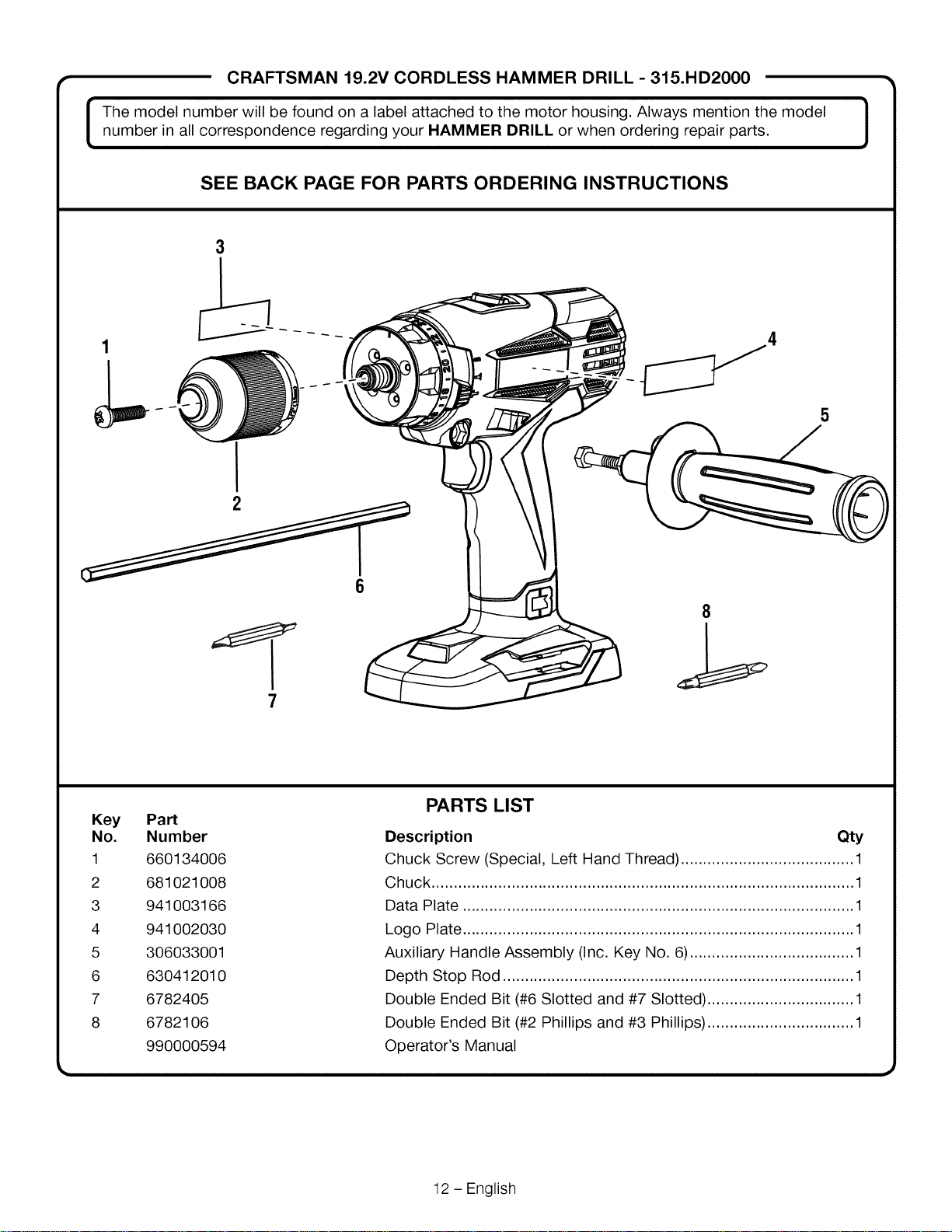
CRAFTSMAN 19.2V CORDLESS HAMMER DRILL - 315.HD2000
The model number will be found on a label attached to the motor housing. Always mention the modelnumber in all correspondence regarding your HAMMER DRILL or when ordering repair parts.
SEE BACK PAGE FOR PARTS ORDERING INSTRUCTIONS
3
1
L
2
5
7
8
Key
No.
1
2
3
4
5
6
7
8
PaN
Number
660134006
681021008
941003166
941002030
306033001
630412010
6782405
6782106
990000594
PARTS LIST
Description Qty
Chuck Screw (Special, Left Hand Thread) ....................................... 1
Chuck ............................................................................................... 1
Data Plate ........................................................................................ 1
Logo Plate ........................................................................................ 1
Auxiliary Handle Assembly (Inc. Key No. 6) ..................................... 1
Depth Stop Rod ............................................................................... 1
Double Ended Bit (#6 Slotted and #7 Slotted) ................................. 1
Double Ended Bit (#2 Phillips and #3 Phillips) ................................. 1
Operator's Manual
12 - English
D
,I
I
A- Keylesschuck (portabrocasde aprietesin
Ilave)
B- Torqueadjustment ring (anillo deajustede
fuerza detorsion)
C- Quickmode selector (selectordemodalidad
rapido)
D- Two-speedgeartrain (Hi-Lo) [engranajede
dosvelocidades(alta-baja)]
E- Level(nivel)
F- Directionof rotation selector (forward/
reverse/centerlock) [selectordel sentidode
rotacion(marchaadelante/atras/seguroenel
centro)]
G- Auxiliary handleassembly (conjunto del
mangoauxiliar)
H- Bit storage(compartimiento parabrocas)
I - Switchtrigger (gatillo del interruptor)
J - Screwdriverbits (brocas dedestornillador)
K- Depthstop rod (barra limitadorade
profundidad)
A- Screw (tornillo)
B- Slot (ranura)
C- Plate(placa)
D- Auxiliary handle(mango auxiliar)
E- Depth stop slot (ranurapara labarra
limitadora de profundidad)
F - Depthstop rod (barra limitadora de
profundidad)
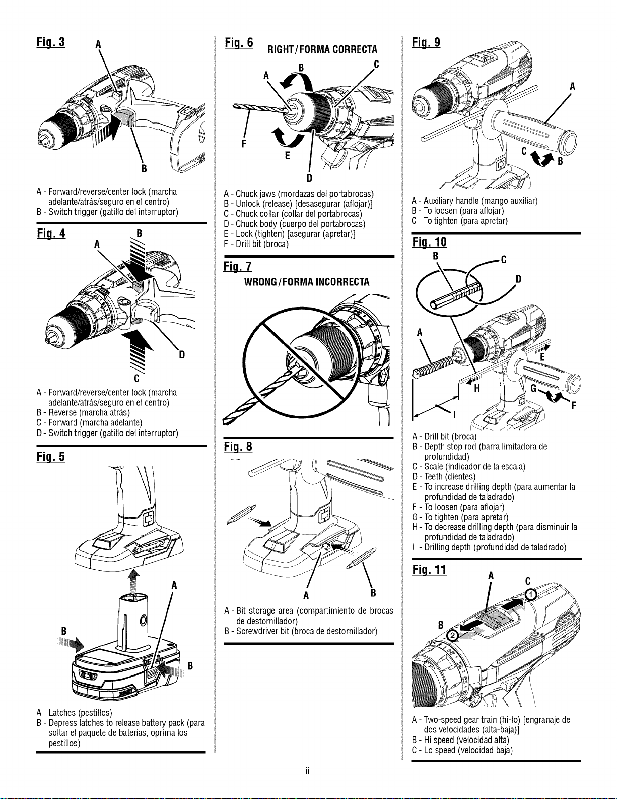
A
A- Forward/reverse/centerlock (marcha
adelante/atrds/seguroenel centro)
B- Switchtrigger (gatillo delinterruptor)
B
A
A- Forward/reverse/centerlock (marcha
adelante/atras/seguroen elcentro)
B- Reverse(marchaatr_,s)
C- Forward (marchaadelante)
D- Switchtrigger (gatillo delinterruptor)
A
A- Latches(pestillos)
B- Depresslatchesto releasebatterypack (para
soltarel paquetedebaterias,oprima los
pestiiios)
RIGHT/FORMA CORRECTA
B C
A
\
F
E
A- Chuckjaws (mordazasdelportabrocas)
B- Unlock(release)[desasegurar(aflojar)]
C- Chuckcollar (collar delportabrocas)
D- Chuckbody (cuerpo delportabrocas)
E- Lock (tighten) [asegurar(apretar)]
F - Drill bit (broca)
WRONG/FORMA INCORRECTA
A B
A-Bit storage area (compartimiento de brocas
dedestornillador)
B- Screwdriver bit (brocadedestornitlador)
A
A-Auxiliaryhandle(mangoauxiliar)
B-Toloosen(paraaflojar)
C- Totighten(paraapretar)
Fi_ .10
E
A- Drill bit (broca)
B- Depthstop rod (barra limitadorade
profundidad)
C- Scale(indicador de laescala)
D- Teeth(dientes)
E- To increasedrilling depth (paraaumentarla
profundidad detaladrado)
F- To loosen(paraaflojar)
G- Totighten (paraapretar)
H- To decreasedrilling depth(para disminuir la
profundidad detaladrado)
I - Drilling depth(profundidad detaladrado)
A
A- Two-speedgeartrain (hi-Io) [engranajede
dos velocidades(alta-baja)]
B- Hispeed(velocidadalta)
C- Lo speed(velocidad baja)
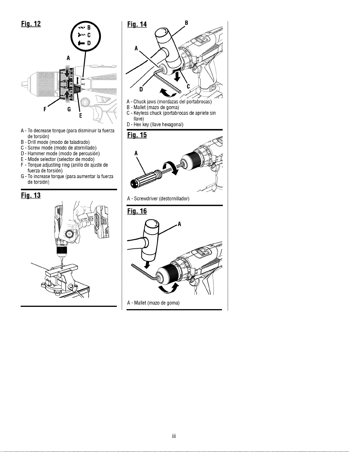
A
F G
E
A- To decreasetorque (paradisminuir lafuerza
detorsi6n)
B- Drill mode (modo detaladrado)
C- Screw mode (modo deatornillado)
D- Hammer mode(modo de percusi6n)
E- Mode selector (selectordemodo)
F- Torqueadjusting ring (anillo de ajustede
fuerza detorsi6n)
G-Toincreasetorque (paraaumentarlafuerza
detorsi6n)
Fi__.13
Fi__.14
A
\
A- Chuckjaws (mordazasdelportabrocas)
B- Mallet(mazode goma)
C- Keylesschuck (portabrocasde aprietesin
Ilave)
D- Hexkey(llave hexagonal)
A
A- Screwdriver(destornitlador)
A- Mallet (mazode goma)

_, ADVERTENCIA Lea todas las advertencias de
seguridad y las instrucciones. El inoumplimiento
de las advertencias e instruooiones puede ocasionar
descarga el_ctrica, fuego o lesiones graves.
Guarde todas las advertencias e instrucciones para
futuras consultas. El termino "herramienta electrica"
empleado en todos los avisos de advertencia enumerados
abajo se refiere alas herramientas electricas de cord6n
(alambricas) y de baterias (inalambricas).
SEGURIDAD EN EL AREA DE TRABAJO
• Mantenga limpia y bien iluminada el _rea de trabajo.
Un &rea de trabajo mal despejada o mal iluminada
propicia accidentes.
• No utilice herramientas motorizadas en atm6sferas
explosivas, como las existentes alrededor de liquidos,
gases y polvos inflamables. Las herramientas electricas
generan chispas que pueden encender el polvo y los
vapores inflamables.
• Mantenga alejados a los niSos y circunstantes al
maniobrar una herramienta el6ctrica. Toda distracci6n
puede causar perdida del control de la herramienta.
SEGURIDAD ELI=CTRICA
• Las clavijas de las herramientas el6ctricas deben
corresponder alas tomas de corriente donde se
conectan. Nunca modifique la clavija de ninguna
forma. No utilice ninguna clavija adaptadora con
herramientas el6ctricas dotadas de contacto a tierra.
Conectando las clavijas originales en las tomas de
corriente donde corresponden se disminuye el riesgo de
una descarga electrica.
• Evite el contacto del cuerpo con las superficies de
objetos que est6n haciendo tierra o est6n conectados
a 6sta, como tuberias, radiadores, estufas y
refrigeradores. Existe un mayor riesgo de descargas
electricas si el cuerpo est& haciendo tierra.
• No exponga las herramientas el6ctricas a la Iluvia ni
a condiciones de humedad. La introducci6n de agua en
una herramienta electrica aumenta el riesgo de descargas
electricas.
• No maltrate el cord6n el6ctrico. Nunca utilice el
cord6n para trasladar, desconectar o tirar de la
herramienta el6ctrica. Mantenga el cord6n alejado
del calor, del aceite, de bordes afilados y de piezas
m6viles. Los cordones electricos dadados o enredados
aumentan el riesgo de descargas electricas.
• AI utilizar una herramienta electrica a la intemperie,
use un cord6n de extensi6n apropiado para el
exterior. Usando un cord6n adecuado para el exterior se
disminuye el riesgo de descargas electricas.
• Si debe operar una herramienta en lugares h6medos,
use un suministro protegido por un interruptor de
circuito con p6rdida a tierra (GFCl). El uso de un GFCI
reduce el riesgo de descargas electricas.
Cargue las baterias solamente con el cargador
indicado. Para utilizar con paquetes de baterias de
niquel-cadmio de 19,2 V o de iones de litio de 19,2 V,
consulte el folleto de la herramienta/aparato/paquete de
baterias/cargador complementario 988000-272.
SEGURIDAD PERSONAL
• Permanezca alerta, preste atenci6n a Io que est6
haciendo y aplique el sentido com_n al utilizar
herramientas el6ctricas. No utilice la herramienta
el6ctrica si est_ cansado o se encuentra bajo los
efectos de alguna droga, alcohol o medicamento.
Un momento de inatenci6n al utilizar una herramienta
el_ctrica puede causar lesiones corporales serias.
• Use equipo de seguridad. Siempre p6ngase
protecci6n ocular. El uso de equipo de seguridad como
mascarilla para el polvo, calzado de seguridad, casco y
protecci6n para los o[dos en las circunstancias donde
corresponda disminuye el riesgo de lesiones.
• Evite un arranque accidental de la unidad. Aseg_rese
de que el interruptor este en la posici6n de apagado
antes de conectar la herramienta. Portar las
herramientas el_ctricas con el dedo en el interruptor,
o conectarlas con el interruptor puesto, propicia
accidentes.
• Retire toda Ilave o herramienta de ajuste antes
de encender la herramienta electrica. Toda Ilave o
herramienta de ajuste dejada en una pieza giratoria de la
herramienta el_ctrica puede causar lesiones.
• No estire el cuerpo para alcanzar mayor distancia.
Mantenga una postura firme y buen equilibrio en
todo momento. De esta manera se Iogra un mejor
control de la herramienta el6ctrica en situaciones
inesperadas.
• Vistase adecuadamente. No vista ropas holgadas
ni joyas. Mantenga el cabello, la ropa y los guantes
alejados de las piezas m6viles. Las ropas holgadas,
las joyas y el cabello largo pueden engancharse en las
piezas m6viles.
• Si se suministran dispositivos para conectar
mangueras de extracci6n y captaci6n de polvo,
aseg_rese de que estas esten bien conectadas y
se usen correctamente. La utilizaci6n de captador de
polvo puede disminuir los peligros relacionados con el
polvo.
• No vista ropas holgadas ni joyas. Rec6jase el cabello
si esta largo. Las ropas holgadas y las joyas, asi como
el cabello largo, pueden resultar atraidas hacia el interior
de las aberturas de ventilaci6n.
• No utilice la unidad al estar en una escalera o en
un soporte inestable. Una postura estable sobre
una superficie s61ida permite un mejor control de la
herramienta el_ctrica en situaciones inesperadas.
EMPLEO Y CUIDADO DE LA HERRAMIENTA
ELI_CTRICA
• No fuerce la herramienta electrica. Utilice la
herramienta electrica adecuada para cada trabajo.
La herramienta el_ctrica adecuada efect0a mejor y de
3 - Espafiol
maneramasseguraeltrabajo,siademassemanejaa la
velocidadparalaqueestadisedada.
• Noutilicelaherramientasielinterruptornoenciende
onoapaga.Cualquierherramientael_ctricaqueno
puedacontrolarseconelinterruptorespeligrosaydebe
repararse.
• Desconecte la clavija del suministro de corriente
o retire el paquete de baterias de la herramienta
electrica, seg_n sea el caso, antes de efectuarle
cualquier ajuste, cambiarle accesorios o guardarla.
Tales medidas preventivas de seguridad reducen
el riesgo de poner en marcha accidentalmente la
herramienta.
• Guarde las herramientas electricas desocupadas
fuera del alcance de los nifios y no permita que las
utilicen personas no familiarizadas con las mismas
o con estas instrucciones. Las herramientas el_ctricas
son peligrosas en manos de personas no capacitadas
en el uso de las mismas.
• Preste servicio alas herramientas electricas. Revise
para ver si hay desalineaci6n o atoramiento de
piezas m6viles, ruptura de piezas o cualquier otra
condici6n que pueda afectar el funcionamiento de la
herramienta. Siesta dafiada la herramienta electrica,
permita que la reparen antes de usarla. Numerosos
aooidentes son causados pot herramientas el_ctrioas
mal cuidadas.
• Mantenga las herramientas de corte afiladas y
limpias. Las herramientas de corte bien cuidadas y
con bordes bien afilados, tienen menos probabilidad de
atascarse en la pieza de trabajo y son mas faciles de
controlar.
• Utilice la herramienta electrica, los accesorios y
brocas, hojas y cuchillas de corte, ruedas de esmeril,
etc. de conformidad con estas instrucciones,
tomando en cuenta las condiciones de trabajo y la
tarea por realizar. Si se utiliza la herramienta el_ctrica
para operaciones diferentes de las indicadas podria
originar una situaci6n peligrosa.
EMPLEO Y CUIDADO DE LA HERRAMIENTA DE
BATERiAS
• $61o cargue el paquete de baterias con el cargador
especificado pot el fabricante. Un cargador adecuado
para un tipo paquete de baterfas puede significar un
riesgo de incendio si se emplea con un paquete de
baterias diferente.
• Utilice las herramientas electricas s61ocon los
paquetes de baterias especificamente indicados.
El empleo de paquetes de baterias diferentes puede
presentar un riesgo de incendio.
• Cuando no este utilizandose el paquete de baterias,
mantengalo lejos de otros objetos metalicos, como
clips, monedas, Ilaves, clavos, tornillos o otros
objetos metalicos, pequefios que puedan establecer
conexi6n entre ambas terminales. Establecer una
conexi6n directa entre las dos terminales de las baterias
puede causar quemaduras o incendios.
• Si se maltratan las baterias, puede derramarse
liquido de las mismas; evite todo contacto con este.
En caso de contacto, lavese con agua. Si el liquido
Ilega a tocar los ojos, ademas busque atenci6n
medica. El I[quido de las baterias puede causar
irritaci6n y quemaduras.
SERVICIO
• Permita que un tecnico de reparaci6n calificado
preste servicio a la herramienta electrica, y s61o
con piezas de repuesto identicas. De esta manera se
mantiene la seguridad de la herramienta el_ctrica.
• AI dar servicio a una herramienta electrica,
s61o utilice piezas de repuesto identicas. Siga
las instrucciones sefialadas en la secci6n
Mantenimiento de este manual. El empleo de piezas
no autorizadas o el incumplimiento de las instrucciones
de mantenimiento puede significar un riesgo de
descarga el6ctrica o de lesiones.
4 - Espa_ol
• AI utilizar taladros de impacto p6ngase protectores
para los oidos. La exposici6n a ruido puede producir
la p_rdida de la audici6n.
• Utilice el o los mangos auxiliares, de venir provistos
junto con la herramienta. Cualquier p_rdida de
control puede causar lesiones personales.
• Sujete las herramientas electricas por las
superficies aisladas de sujeci6n al efectuar una
operacion en la cual la herramienta de corte pueda
entrar en contacto con cables ocultos o con su
propio cord6n electrico. Todo contacto de una
herramienta con un cable cargado carga las piezas
metalicas expuestas de la herramienta y da una
descarga el_ctrica al operador.
• Familiaricese con su herramienta electrica. Lea
cuidadosamente el manual del operador. Aprenda
sus usos y limitaciones, asi como los posibles
peligros especificos de esta herramienta electrica.
Con el cumplimiento de esta regla se reduce el riesgo
de una descarga el_ctrica, incendio o lesi6n seria.
• Siempre use protecci6n ocular con laterales
protectores con la marca de cumplimiento
con la norma ANSI Z87.1 al ensamblar piezas,
utilizar la herramienta o Ilevar a cabo tareas de
mantenimiento. Con el cumplimiento de esta regla se
reduce el riesgo de lesiones corporales serias.
• Prot_jase los pulmones. Use una careta o
mascarilla contra el polvo si la operaci6n genera
mucho polvo. Con el cumplimiento de esta regla se
reduce el riesgo de lesiones serias.
• Prot_jase los oidos. Durante periodos prolongados
de utilizaci6n del producto, p6ngase protecci6n
para los oidos. Con el cumplimiento de esta regla se
reduce el riesgo de lesiones corporales serias.
• No se necesita conectar a una toma de corriente
las herramientas de baterias; por Io tanto, siempre
estan en condiciones de funcionamiento. Est_
consciente de los posibles peligros cuando no
est_ usando la herramienta de baterias o cuando
est_ cambiando los accesorios de la misma. Con el
cumplimiento de esta regla se reduce el riesgo de una
descarga el_ctrica, incendio o lesi6n corporal seria.
• No coloque herramientas de baterias ni las baterias
mismas cerca del fuego odel calor. De esta manera
se reduce el riesgo de explosiones y de lesiones.
• No aplaste, deje caer o dahe de baterias. Nunca
utilice una bateria o cargador que se ha caido,
aplastado, recibido un golpe contundente o ha sido
da5ado(a) de alguna manera. Las baterias daSadas
pueden sufrir explosiones. Deseche de inmediato toda
bateria que haya sufrido una caida o cualquier da_o.
• Las baterias pueden explotar en presencia de
fuentes de inflamaci6n, como los pilotos de gas.
Para reducir el riesgo de lesiones serias, nunca use
un producto inalambrico en presencia de llamas
expuestas. La explosi6n de una bateria puede lanzar
fragmentos y compuestos quimicos. Si ha quedado
expuesto a la explosi6n de una bateria, lavese de
inmediato con agua.
• No cargue herramientas de baterias en lugares
mojados o ht_medos. Con el cumplimiento de esta
regla se reduce el riesgo de una descarga el_ctrica.
• Para obtener resultados 6ptimos, debe cargar
la herramienta de baterias en un lugar donde la
temperatura est_ entre 10 y 38 °C (entre 50 y 100
°F}. No guarde la herramienta a la intemperie ni en el
interior de vehiculos.
• En condiciones extremas de uso o temperatura las
baterias pueden emanar liquido. Si el liquido Ilega
a tocarle la piel, lavese de inmediato con agua y
jab6n. Si le entra liquido en los ojos, laveselos con
agua limpia por Io menos 10 minutos, y despues
busque de inmediato atenci6n medica. Con el
cumplimiento de esta regla se reduce el riesgo de
lesiones corporales serias.
• Guarde estas instrucciones. ConsOltelas con
frecuencia y empl_elas para instruir a otras personas
que puedan utilizar esta herramienta. Si presta
a alguien esta herramienta, facilitele tambi_n las
instrucciones.
5 - EspaSol
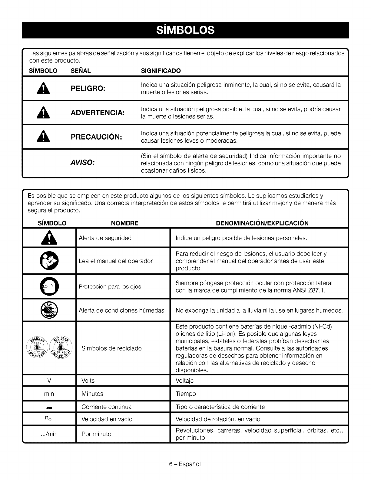
Lassiguientespalabrasdese_alizaci6nysussignificadostienenelobjetodeexplicarlosnivelesderiesgorelacionados
conesteproducto.
SiMBOLO SENAL SIGNIFICADO
,_ PELIGRO:
Indica una situaci6n peligrosa inminente, la cual, si no se evita, causara la
muerte o lesiones serias.
ADVERTENCIA:
Indica una situaci6n peligrosa posible, la cual, si no se evita, podria causar
la muerte o lesiones serias.
,_ PRECAUCION:
Indica una situaci6n potencialmente peligrosa la cual, si no se evita, puede
causar lesiones leves o moderadas.
AVISO:
(Sin el sfmbolo de alerta de seguridad) Indica informaci6n importante no
relacionada con ningOn peligro de lesiones, como una situaci6n que puede
ocasionar da_os fisicos.
Es posible que se empleen en este producto algunos de los siguientes sfmbolos. Le suplicamos estudiarlos y
aprender su significado. Una correcta interpretaci6n de estos simbolos le permitira utilizar mejor y de manera mas
segura el producto.
SJMBOLO NOMBRE
A
@
O
@
DENOMINACION/EXPLICACION
Alerta de seguridad
Lea el manual del operador
Protecci6n para los ojos
Alerta de condiciones hOmedas
Simbolos de reciclado
Indica un peligro posible de lesiones personales.
Para reducir el riesgo de lesiones, el usuario debe leer y
comprender el manual del operador antes de usar este
producto.
Siempre p6ngase protecci6n ocular con protecci6n lateral
con la marca de cumplimiento de la norma ANSI Z87.1.
No exponga la unidad a la Iluvia ni la use en lugares hOmedos.
Este producto contiene baterfas de nfquel-cadmio (Ni-Cd)
o iones de litio (Li-ion). Es posible que algunas leyes
municipales, estatales o federales prohiban desechar las
baterfas en la basura normal. Consulte alas autoridades
reguladoras de desechos para obtener informaci6n en
relaci6n con las alternativas de reciclado y desecho
disponibles.
V Volts Voltaje
min Minutos Tiempo
..--, Corriente continua Tipo o caracteristica de corriente
no Velocidad en vacio Velocidad de rotaci6n, en vacio
.../min Por minuto Revoluciones, carreras, velocidad superficial, 6rbitas, etc.,
por minuto
6 - Espa_ol
ESPECIFICACIONES DEL PRODUCTO
Portabrocas .................. 1/2 pulg. (13 mm), de apriete sin Ilave
Motor ............................................................ 19,2 V, corr. cont.
Interruptor .................................................... Velocidad variable
Velocidad en vacfo ........................ 0-375/0-1 600 r/min (RPM)
FAMILIARiCESE CON EL TALADRO DE
PERCUSI(3N
Vea la figura 1, pbgina i.
Para usar este producto con la debida seguridad se debe
comprender la informaci6n indicada en la herramienta
misma yen este manual, y se debe comprender tambien
el trabajo que intenta realizar. Antes de usar este producto,
familiaricese con todas las caracteristicas de funcionamiento
y normas de seguridad del mismo.
MANGO AUXILIAR
El taladro esta equipado de un mango auxiliar para facilitar
su manejo y evitar la perdida de control.
COMPARTIMIENTO DE BROCAS DE
DESTORNILLADOR
Las brocas de destornillador suministradas con el taladro
pueden colocarse en el compartimiento situado en la base
de la unidad.
GOLPES PeR MINUTe
Esta herramienta ofrece una velocidad de
0-5 600/0-24 000 GPM (golpes por minuto). La frecuencia de
impacto se expresa como el nOmero de golpes que
aplica la herramienta cada minuto.
BARRA LIMITADORA DE PROFUNDIDAD
Con esta herramienta se suministra una barra limitadora de
profundidad para ayudar a controlar la profundidad de los
orificios taladrados.
SELECTOR DEL SENTIDO DE ROTACI(3N
(MARCHA ADELANTE, ATRAS, SEGURO EN EL
CENTRe)
El taladro dispone de un selector de sentido de giro (marcha
adelante/atras/seguro en el centro) situado arriba del gatillo
del interruptor para cambiar el sentido de giro de la broca. Si
Velocidad de percusi6n ...................... 0-5 600/0-24 000 GPM*
Embrague ........................................................... 24 posiciones
Fuerza de torsi6n ........................ hasta 465 Ib.pulg. (47,5 Nm)
*Golpes por minuto
se pone el gatillo del interruptor en la posici6n de APAGADO,
(seguro en el centro), se evita el peligro de arrancar
accidentalmente la herramienta cuando no este usandose.
PORTABROCAS DE APRIETE SIN LLAVE
El portabrocas de apriete sin Ilave permite apretar o aflojar a
mano la broca en las mordazas del portabrocas.
NIVEL
Un niveau est situe sur le dessus du Iogement du moteur pour
faire en sorte que la meche de pergage demeure a la m_me
hauteur pendant I'utilisation.
SELECTOR DE MODALIDAD RAPIDO
El selector de modalidad permite escoger fuerza de torsi6n
maxima, taladrado de percusi6n y la capacidad de enroscar
tornillos con fuerza de torsi6n ajustada por el usuario.
ANILLO DE AJUSTE DE FUERZA DE TORSI(3N
El taladro incorpora un embrague de 24 posiciones. El anillo
de ajuste de la fuerza de torsi6n puede girarse para escoger
la cantidad correcta de torsi6n necesaria en cada caso.
ENGRANAJE DE DOS VELOCIDADES
El engranaje de dos velocidades fue creado para taladrar o
atornillar a velocidad BAJA posici6n (1) o ALTA
posici6n (2). Un interruptor deslizante en la parte superior del
taladro permite seleccionar velocidad BAJA,
posici6n (1) o ALTA, posici6n (2).
VELOCIDAD VARIABLE
La velocidad de giro se incrementa gradualmente al aplicar
mayor presi6n en el gatillo, y a la inversa, se reduce al
disminuir esta presi6n.
CALIFORNIA - PROPUESTA DE LEY NUM. 65
,_ ADVERTENCIA: Este product y el polvo que crea pueden contener productos quimicos, como plomo, queen el estado
de California se reconocen como cancerigenos o causantes de defectos de nacimiento u otros dados reproductivos./_,_vese
las manes despues de utilazar el aparate.
Algunos ejemplos de estas sustancias quimicas son:
• plomo de las pinturas a base de plomo,
• silicio cristalino de los ladrillos, del cemento y de otros productos de albadileria, y
• arsenico y cromo de la madera quimicamente tratada.
El riesgo de la exposici6n a estos compuestos varia, segOn la frecuencia con que se realice este tipo de trabajo. Para
reducir la exposici6n personal, trabaje en areas bien ventiladas, y con equipo de seguridad aprobado, tal como las caretas
para el polvo especialmente dise_adas para filtrar partfculas microsc6picas.
7 - Espa_ol
DESEMPAQUETADO
Este producto requiere armarse.
• Extraiga cuidadosamente de la caja la herramienta y los
accesorios. Compruebe que esten presentes todos los
articulos enumerados en la lista de empaquetado.
_, ADVI=RTI=NClA; No use este producto si no esta
totalmente ensamblado o si alguna pieza falta o esta
dadada. Si utiliza un producto que no se encuentra
ensamblado de forma correcta y completa, puede sufrir
lesiones graves.
• Inspeccione cuidadosamente la herramienta, para
verificar que no haya sufrido ninguna rotura o dado
durante el transporte.
• No deseche el material de empaquetado hasta que haya
inspeccionado la herramienta con cuidado y la haya
utilizado satisfactoriamente.
• Si hay piezas dadadas o faltantes, sirvase Ilamar al
1-800-932-3188, donde le brindaremos asistencia.
LISTA DE EMPAQUETADO
Taladro de percusi6n con conjunto de mango auxiliar
Barra limitadora de profundidad
Brocas de destornillador
Manual del operador
_ ADVERTENCIA: Si hay piezas dadadas o faltantes,
no utilice esta herramienta sin haber reemplazado las
piezas dadadas o faltantes. Usar este producto con
partes dadadas o faltantes puede causar lesiones
serias al operador.
A,
A
ADVERTENCIA: No intente modificar esta
herramienta ni fabricar accesorios no recomendados
para ella. Cualquier alteraci6n o modificaci6n constituye
maltrato y puede causar una condici6n peligrosa, con
las consecuentes lesiones corporales graves.
ADVERTENCIA: Para evitar un arranque accidental
que podria causar lesiones corporales serias, siempre
desmonte de la herramienta el paquete de baterias al
montarle piezas a aquella.
INSTALACI()N DEL MANGO AUXILIAR
Vea la figura 2, pbgina i.
_k ADVI=RTI=NClA; Siempre utilice el mango auxiliar
cuando emplee esta herramienta para resistir mejor las
reacciones de fuerza de torsi6n. Si este producto se
atora o se cala, se podrian producir lesiones personales
graves.
Este taladro esta provisto de un mango auxiliar que facilita su
manejo y ayuda a evitar la perdida de control.
• Introduzca el tornillo a traves de la ranura del taladro y
empOjelo hasta el fondo.
• Coloque la placa y el mango auxiliar en el tornillo y
aprietelos.
• Introduzca el extremo de la barra limitadora de
profundidad en la ranura situada en la parte posterior de
la placa.
A
A
ADVERTENCIA: No permita que su familarizaci6n
con las herramientas Io vuelva descuidado. Tenga
presente que basta un instante de descuido para que
se produzca una lesi6n grave.
ADVERTENCIA: Siempre retire el paquete de
baterias de la herramienta cuando este ensamblando
partes, realizando ajustes, limpiando o cuando esta
no este en uso. Retirando el paquete de baterias se
evita arrancar accidentalmente la unidad, Io cual puede
causar lesiones serias.
ADVERTENCIA: Siempre p6ngase protecci6n ocular
con protecci6n lateral con la marca de cumplimiento
de la norma ANSI Z87.1. La inobservancia de esta
advertencia puede permitir que los objetos lanzados
hacia los ojos puedan provocarle lesiones graves.
_ ADVERTENCIA: No utilice ningOn aditamento o
accesorio no recomendado por el fabricante de esta
herramienta. El empleo de aditamentos o accesorios no
recomendandos puede causar lesiones graves.
APLICACIONES
Esta herramienta puede emplearse para los fines siguientes:
• Taladrado de percusi6n en hormig6n, ladrillo y otros tipos
de mamposteria
• Taladrado productos de madera (madera aserrada,
madera contrachapada, paneles, madera compuesta
y madera dura), ceramica, plasticos, fibra de vidrio y
material laminado, y metales; Enroscar tornillos con
puntas de destornillador
8 - Espa_ol
GATILLO DEL INTERRUPTOR DE VELOCIDAD
VARIABLE
Vea la figura 3, pbgina ii.
El gatillo de velocidad variable produce mayor velocidad
cuanta mayor presi6n se aplica en el gatillo, y menor
velocidad cuanta menor presi6n se aplica en el mismo.
Para ENCENDER el taladro, oprima el gatillo del interruptor.
Para DETENER el taladro, suelte el gatillo del interruptor y
permita que se detenga completamente el portabrocas.
NOTA: Un silbido o zumbido que viene del interruptor
durante el uso es una parte normal de la funci6n del
interruptor.
Evite hacer funcionar el taladro a baja velocidad por periodos
largos. El trabajo constante a velocidades bajas puede
causar recalentamiento del taladro. De ocurrir esto, enfrie el
taladro haciendolo funcionar sin carga a plena velocidad.
SELECTOR DE SENTIDO DE ROTACION
(MARCHA ADELANTE, ATR._.S, SEGURO EN EL
CENTRO)
Vea la figura 4, pbgina ii.
AVISO: Para no dadar el engranaje, antes de cambiar
el sentido de rotaci6n espere a que el portabrocas se
detenga por completo.
Ajuste el selector de sentido de rotaci6n en la posici6n de
APAGADO (seguro en el centro) para bloquear el gatillo
del interruptor y ayudar a prevenir un arranque accidental
cuando no este en uso.
Ubique el selector de sentido de rotaci6n a la izquierda del
gatillo del interruptor para taladrar hacia adelante. Ubique el
selector a la derecha del gatillo del interruptor para taladrar
hacia atras.
NOTA: El taladro no funciona a menos que se empuje el
selector de direcci6n de giro completamente a la izquierda o
derecha.
,_ ADVERTENCIA: Las herramientas de baterfas
siempre estAn en condiciones de funcionamiento.
Bloquee el interruptor cuando no este en uso o Io Ileve
a su lado, al instalar o extraer el paquete de baterfas y al
instalar o extraer brocas.
INSTALACION/DESMONTAR DEL PAQUETE DE
BATER|AS
Vea la figura 5, pbgina ii.
• Bloquee el gatillo del interruptor.
• Coloque el paquete de baterias en el producto como se
muestra.
• AsegOrese de que los pestillos situados a ambos lados
del paquete de baterias entren completamente en su
lugar con un chasquido y de que el paquete quede
bien asegurado en la herramienta antes de comenzar a
utilizarla.
• Oprima los pestillos para extraer el paquete de baterias.
INSTALACION / DESMONTAR DE LAS BROCAS
Vea las figuras 6 - 8, pbgina ii.
Las flechas en el portabrocas sin Ilaves indican en que
direcci6n girar el cuerpo del portabrocas para apretar o soltar
la broca.
No utilice ninguna Ilave para apretar o aflojar las mordazas
del portabrocas.
• Para instalar las brocas, bloquee el gatillo del
interruptor.
• Abra o cierre las mordazas del portabrocas a tal punto
que la abertura sea levemente mas grande que la broca
deseada.
• Levante la parte delantera del taladro ligeramente e
inserte la broca.
_, ADVERTENCIA: AsegOrese de introducir la broca
recta en las mordazas del portabrocas. No introduzca
en angulo la broca en las mordazas del portabrocas
para despues apretarla. Podria causar que la broca
salga disparada del taladro, y por consecuencia,
posibles lesiones corporales serias, o dados al
portabrocas.
• Con la otra mano, gire el cuerpo del portabrocas para
cerrar y apretar las mordazas del portabrocas.
_, ADVERTENCIA: No sujete con la mano el cuerpo
del portabrocas con la intenci6n de usar la fuerza de
giro del taladro para apretar la broca en las mordazas.
El portabrocas podria resbalarsele en la mano, o esta
misma resbalarse y entrar en contacto con la broca
que gira. Esto puede causar un accidente y lesiones
corporales graves.
• Para extraer las brocas, bloquee el gatillo del interruptor
y abra las mordazas del portabrocas.
• La broca suministrada con el taladro pueden colocarse en
el compartimiento situado en la base de la unidad.
EMPLEO DEL CONJUNTO DEL MANGO
AUXILIAR
Vea las figuras 9 a 10, pbgina ii.
Este taladro est& provisto de un mango auxiliar que facilita
su manejo y ayuda a evitar la perdida de control. El mango
montarse en el lado opuesto para utilizarse con la mano
izquierda.
Aseg0rese de que el mango auxiliar quede firmemente
apretado contra la abrazadera de graduaci6n de
profundidad. De esta manera, la barra limitadora de
profundidad se ajusta a la profundidad deseada de
taladrado. Tambien queda asegurado el mango auxiliar.
NOTA- Para mayor comodidad y facilidad al comenzar a
perforar, la tuerca hexagonal est& hundida dentro de la
ranura moldeada del mango auxiliar.
La barra limitadora de profundidad sirve para controlar la
profundidad de los agujeros taladrados.
9 - Espadol
NOTA: Cuando esta bien instalada, los dientes de la barra
limitadora de profundidad coinciden con el indicador de
dientes de la abrazadera correspondiente.
Ajuste la barra limitadora de profundidad de tal manera
que la broca rebase la punta de la barra en la medida de la
profundidad de taladrado deseada.
AI taladrar con la barra limitadora de profundidad instalada,
la profundidad deseada del orificio se alcanza cuando la
punta de la barra toca la superficie de la pieza de trabajo.
AJUSTE DEL CONJUNTO DEL MANGO
AUXILIAR
Vea la figura 9, pbgina ii.
• Afloje el conjunto del mango; para ello gire a la izquierda
el mango.
• Gire el conjunto del mango a la posici6n de trabajo
deseada.
Apriete firmemente el conjunto del mango auxiliar; para
ello, gfrelo a la derecha.
AJUSTE DE LA FUERZA DE TORSION
Vea la figura 12, pagina ii.
Emplee brocas con punta de carburo y seleccione el modo
de percusi6n al taladrar en materiales duros como ladrillo,
hormig6n, etc.
Utilice brocas puntas de carburo y seleccione el modo tal-
adro al perforar materiales de superficies duras y quebradi-
zas tal como la Iosa, etc.
Utilice brocas helicoidales, sierras caladoras, etc. y el modo
taladro al perforar materiales blandos.
Gire el anillo de ajuste a la configuraci6n de torsi6n
adecuada para el tipo de material y tamado de tornillo que
esta utilizando.
• Gire el anillo de ajuste a la marca deseada.
• 1 - 4 Para introducir tornillos peque_os
• 5 - 8 Para introducir tornillos en material blando
• 9 - 12 Para introducir tornillos en materiales
blandos o duros
• 13 - 16 Para introducir tornillos en madera dura
AJUSTE DE LA BARRA LIMITADORA DE
PROFUNDIDAD
Vea la figura 10, pbgina iii.
• Asegure el gatillo del interruptor; para ello, coloque el
selector de sentido de rotaci6n en la posici6n central.
• Afloje el conjunto del mango auxiliar girando la perilla
hacia la izquierda.
• Ajuste la barra limitadora de profundidad de tal manera
que la broca rebase la punta de la barra en la medida de
la profundidad de taladrado deseada.
• Apriete el conjunto del mango auxiliar girando la perilla
hacia la derecha.
TREN DE ENGRANAJES DE DOS
VELOCIDADES
Vea la figura 11, pbgina ii.
• Seleccione la velocidad LO (1) (BAJA} para aplicaciones
que requieren una mayor potencia y torsi6n.
• Seleccione la velocidad HI (2} (ALTA) para aplicaciones de
taladrado o atomillado rapidas.
AVISO: Nunca cambie de gama de velocidad mientras
este funcionando la herramienta. El incumplimiento
de esta precauci6n puede producir dados serios en el
taladro.
• 17-23
Para introducir tornillos grandes
Para taladrado pesado
TALADRADO/INTRODUCCION DE TORNILLOS
Vea las figuras 10 a 11, pagina ii.
Un niveau est situe sur tedessus du logement du moteur pour faire
en sorte que la meche de pergage demeure & la m_me hauteur
pendant I'utitisation.
• Instalar el mango auxiliar.
• Gire el selector de modo a la posici6n del tomillo (_.',).
• Revise el selector de sentido de rotaci6n para ver siesta
en la posici6n correcta (marcha o atras).
• Use velocidad LO (1) BAJA para aplicaciones de
alta fuerza de torsi6n y velocidad HI (2) ALTA para
aplicaciones rapidas de taladrado o con destomilladores.
Consulte tren de Tren de engranajes de dos velocidades.
• Asegure la pieza de trabajo en una prensa de banco, o
con abrazaderas de mano, para evitar que rote al girar la
broca.
• Sostenga firmemente el taladro y coloque la broca en el
punto donde va a taladrar, o en el punto donde el tornillo
vaya a introducir este.
A
EMBRAGUE DE FUERZA DE TORSION
AJUSTABLE
Vea la figura 12, pbgina ii.
El taladro esta provisto de un embrague de torsi6n ajustable
para introducir diferentes tipos de tornillos en distintos
materiales. Para usar los ajustes de la fuerza de torsi6n, gire
el selector de modo para ponerlo en el modo de atomillado
(_-,-). (El modo de taladrado (_) o percusi6n (*.'_'_) es para
operaciones a toda la fuerza de torsi6n.) El ajuste adecuado
depende del tipo de material y del tamado del tornillo.
10 - Espa_ol
ADVERTENCIA: No introduzca tornillos donde
pudiera haber cables ocultos detras de la superficie.
Todo contacto de una herramienta con un cable
cargado carga las piezas metalicas expuestas de la
herramienta y da una descarga electrica posiblemente
al operador. Si debe introducir tomillos donde pudiera
haber cables ocultos, siempre sujete la herramienta por
las superficies aisladas de sujeci6n (mango) al efectuar
una operaci6n para evitar una descarga electrica al
operador.
Oprimaelgatillodelinterruptorparaencendereltaladro.
Introduzcalabrocaenlapiezadetrabajoaplicando
justamentelapresi6nsuficienteparamantenerlabroca
perforandoelmaterial.Nofuerceeltaladroniaplique
presi6nlateralparaovalarelorificio.Permitaquela
herramientarealiceeltrabajo.
A
ADVERTENCIA: AI taladrar, este preparado por
si se atasca la broca al traspasar la pieza de trabajo.
Cuando ocurren estas situaciones, el taladro presenta
una tendencia a trabarse y dar un contragolpe en
la direcci6n opuesta, y podria causar una perdida
de control al perforar el material. Si usted no esta
preparado, esta perdida de control podria ser causa de
lesiones serias.
• Para taladrar superficies lisas y duras utilice un punz6n
de marcar para se_alar la ubicaci6n de la perforaci6n. De
esta manera se evita que la broca se desplace del centro
al iniciar la perforaci6n.
• Si se atora la broca en la pieza de trabajo, o si se detiene
el taladro, apague de inmediato la herramienta. Retire
la broca de la pieza de trabajo y determine la raz6n
causante del atoramiento.
NOTA: Este taladro tiene un freno electrico. Cuando se
suelta el gatillo del interruptor, el portabrocas deja de girar.
Cuando el freno funciona correctamente, pueden verse
chispas a traves de las ranuras de ventilaci6n de la caja del
motor. Es un efecto normal de la acci6n del freno.
TALADRADO EN MADERA Y EN METAL
Para obtener un desempe_o 6ptimo de la unidad, utilice
brocas de acero de alta velocidad para taladrado en madera.
o en metal. Seleccione el modo de taladrado. Comience a
taladrar a una velocidad muy baja para impedirle a la broca
abandonar el punto inicial.
Taladrado en madera-
• Aumente la velocidad a medida que la broca penetra en
el material.
• AI taladrar orificios de lado a lado, coloque un bloque de
madera detras de la pieza de trabajo para evitar producir
orillas deshilachadas o astilladas en la parte posterior del
orificio.
Taladrado en metal y en acero:
• Aplique aceite de baja viscosidad en la broca para evitar
el recalentamiento de la misma. El aceite prolonga la
vida de servicio de la broca y aumenta la eficacia de la
operaci6n de taladrado.
• Mantenga una velocidad y una presi6n tales que permitan
taladrar sin recalentar la broca. Si se aplica demasiada
presi6n:
• Se recalienta el taladro;
• Se gastan los cojinetes;
• Se doblan o queman las brocas; y
• Se producen orificios descentrados o de forma irregular.
• AI taladrar agujeros grandes en metal, comience con una
broca peque_a y termine con una grande.
TALADRADO EN OBRAS DE ALBANILER|A
Para obtener un desempe_o 6ptimo de la unidad, utilice
brocas de impacto con puntas de carburo para albadileria al
taladrar en ladrillo, hormig6n, etc.
• Ponga el bot6n de ajuste a la izquierda para el modo de
taladrado de percusi6n.
• Para obtener resultados 6ptimos en ladrillo, aplique
presi6n leve y velocidad mediana.
• En materiales duros como el hormig6n, aplique presi6n
adicional.
• AI taladrar orificios en azulejo o baldosa, practique
con una pieza de desecho para determinar la mejor
combinaci6n de velocidad y presi6n. Comience a taladrar
a una velocidad muy baja para impedirle a la broca
abandonar el punto inicial.
11 - Espa_ol
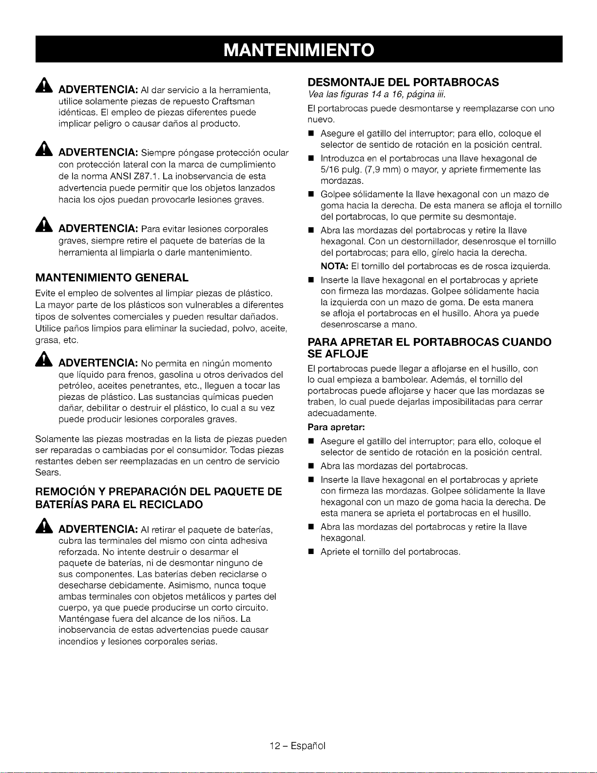
A
A
,il
ADVERTENClA: AI dar servicio a la herramienta,
utilice solamente piezas de repuesto Craftsman
identicas. El empleo de piezas diferentes puede
implicar peligro o causar dados al producto.
ADVERTENClA: Siempre p6ngase protecci6n ocular
con protecci6n lateral con la marca de cumplimiento
de la norma ANSI Z87.1. La inobservancia de esta
advertencia puede permitir que los objetos lanzados
hacia los ojos puedan provocarle lesiones graves.
ADVERTENClA: Para evitar lesiones corporales
graves, siempre retire el paquete de baterfas de la
herramienta al limpiarla o darle mantenimiento.
MANTENIMIENTO GENERAL
Evite el empleo de solventes al limpiar piezas de pl&stico.
La mayor parte de los pl&sticos son vulnerables a diferentes
tipos de solventes comerciales y pueden resultar dadados.
Utilice pados limpios para eliminar la suciedad, polvo, aceite,
grasa, etc.
_i ADVERTENCIA: No permita en ning0n momento
que Nquido para frenos, gasolina u otros derivados del
petr61eo, aceites penetrantes, etc., Ileguen a tocar las
piezas de pl&stico. Las sustancias qufmicas pueden
dadar, debilitar o destruir el pl&stico, Io cual a su vez
puede producir lesiones corporales graves.
Solamente las piezas mostradas en la lista de piezas pueden
ser reparadas o cambiadas por el consumidor. Todas piezas
restantes deben ser reemplazadas en un centro de servicio
Sears.
REMOCI()N Y PREPARACI()N DEL PAQUETE DE
BATERiAS PARA EL RECICLADO
,&
ADVERTENCIA: AI retirar el paquete de baterfas,
cubra las terminales del mismo con cinta adhesiva
reforzada. No intente destruir o desarmar el
paquete de baterfas, ni de desmontar ninguno de
sus componentes. Las baterfas deben reciclarse o
desecharse debidamente. Asimismo, nunca toque
ambas terminales con objetos met&licos y partes del
cuerpo, ya que puede producirse un corto circuito.
Mantengase fuera del alcance de los nifios. La
inobservancia de estas advertencias puede causar
incendios y lesiones corporales serias.
DESMONTAJE DEL PORTABROCAS
Vea las figuras 14 a 16, pagina iii.
El portabrocas puede desmontarse y reemplazarse con uno
nuevo.
• Asegure el gatillo del interruptor; para ello, coloque el
selector de sentido de rotaci6n en la posici6n central.
• Introduzca en el portabrocas una Ilave hexagonal de
5/16 pulg. (7,9 mm) o mayor, y apriete firmemente las
mordazas.
• Golpee s61idamente la Ilave hexagonal con un mazo de
goma hacia la derecha. De esta manera se afloja el tornillo
del portabrocas, Io que permite su desmontaje.
• Abra las mordazas del portabrocas y retire la Ilave
hexagonal. Con un destomillador, desenrosque el tomillo
del portabrocas; para ello, gffelo hacia la derecha.
NOTA: El tornillo del portabrocas es de rosca izquierda.
• Inserte la Ilave hexagonal en el portabrocas y apriete
con firmeza las mordazas. Golpee s61idamente hacia
la izquierda con un mazo de goma. De esta manera
se afloja el portabrocas en el husillo. Ahora ya puede
desenroscarse a mano.
PARA APRETAR EL PORTABROCAS CUANDO
SE AFLOJE
El portabrocas puede Ilegar a aflojarse en el husillo, con
Io cual empieza a bambolear. Adem&s, el tomillo del
portabrocas puede aflojarse y hacer que las mordazas se
traben, Io cual puede dejarlas imposibilitadas para cerrar
adecuadamente.
Para apretar:
• Asegure el gatillo del interruptor; para ello, coloque el
selector de sentido de rotaci6n en la posici6n central.
• Abra las mordazas del portabrocas.
• Inserte la Nave hexagonal en el portabrocas y apriete
con firmeza las mordazas. Golpee s61idamente la Nave
hexagonal con un mazo de goma hacia la derecha. De
esta manera se aprieta el portabrocas en el husillo.
• Abra las mordazas del portabrocas y retire la Nave
hexagonal.
• Apriete el tomillo del portabrocas.
12 - Espafiol


Your Home
Forexperttroubleshooting and homesolutionsadvice:
aHa e
zz For repair- in your home - of all major brand appliances,
lawn and garden equipment, orheating and cooling systems,
nomatterwhomadeit, nomatterwhosold it!
Forthe replacement parts, accessories and
owner's manuals that you need to do-it-yourself.
For Sears professional installation of home appliances
and items like garage door openers and water heaters.
;;;;;;;;;;;;;;;;;;;;
iiiiiiiiiiiiiiiiiiii
;;;;;;;;;;;;;;;;;;;;
;;;;;;;;;;;;;;;;;;;;
;;;;;;;;;;;;;;;;;;;;
;;;;;;;;;;;;;;;;;;;;
;;;;;;;;;;;;;;;;;;;;
;;;;;;;;;;;;;;;;;;;;
;;;;;;;;;;;;;;;;;;;;
!i!i!_ilililililililililililililililililili
1-800-4-MY-HOME ® (1-800-4694663)
Call anytime, day or night (U.S.A. and Canada)
www.sears.com www.sears.ca
Our Home
For repair of carry-in items like vacuums, lawn equipment,
and electronics, call anytime for the location of your nearest
Sears Parts & Repair Service Center
1-800-488-1222 (U.S.A.) 1-800-469-4663 (Canada)
www.sears.com www.sears.ca
To purchase a protection agreement on a product serviced by Sears:
1-800-827-6655 (U.S.A.) 1-800-361-6665 (Canada)
Para pedir servicio de reparaci6n
a domicilio, y para ordenar piezas:
1-888-SU-HOGAR ®
(1-888-784-6427) .....
Au Canada pour service en fran£ais:
1-800-LE-FOYER Mc
(1-800-533-6937)
www.sears.ca
TM SM
® Registered Trademark / Trademark / Service Mark of Sears Brands, LLC
TM
® Marca Registrada / Marca de Fabrica / SMMarca de Servicio de Sears Brands, LLC
MCMarque de commerce / MDMarque depos6e de Sears Brands, LLC ® Sears Brands, LLC