Loading ...
Loading ...
Loading ...
12
13
MAINTENANCE INSTRUCTIONS FOR
SMALL AND LARGE BYPASS HUMIDIFIERS
9
6
3
7
8
5
2
1
4
1. Note Humidifier Control setting and turn dial to the “OFF” position.
2. Turn off water supply. Turn the integral bypass damper (3) to the SUMMER position.
3. Press the tabs in the latches on the top and bottom of front cover (1) and pull cover off base with
both hands. Set aside.
4. Carefully pull the plastic feed tube (2) out of the distribution tray (5) at the top of the evaporative
assembly (4). Pull this assembly out by grasping at top and tipping out.
5. Unsnap the distribution tray (5) from the scale control insert (8). Lightly scrape out or brush off
any mineral deposits, being careful not to stretch or loosen the synthetic fabric liner. Soaking
the tray in vinegar or a lime‑removing agent is helpful when trying to remove stubborn mineral
deposits.
6. Slide the Humidifier Pad (7) out from the scale control insert (8). Clean the scale control
insert of mineral deposits. Replace the Humidifier Pad (Part No. P110‑1045 for Small Bypass
Humidifier and Part No. P110‑3545 for Large Bypass Humidifier) with a new Humidifier Pad.
Slide the Humidifier Pad back into the scale control insert with the colored spot up and snap the
distribution tray (5) back into place.
7. Inspect the plastic feed tube (2) by gently flexing it and looking for cracks or signs of wear.
Replace tube if it is cracked, brittle, or has been damaged.
8. Reinstall the evaporative assembly (4) into the humidifier by fitting its drain into the round
receptacle at the base of the humidifier. Push the assembly in at the top until it snaps into place.
Push the end of the feed tube back firmly into the distribution tray and replace the front cover.
9. Remove the drain line (9) from the bottom of the humidifier. If applicable, flex it to loosen any
mineral deposits or blockage. Then flush it with water under pressure. If it does not properly
clear, replace it. Slip drain line back onto the drain fitting. Make sure the drain line has a
constant downward slope and is not flattened or blocked.
10. Turn on the water supply. Return integral bypass damper to appropriate position.
11. Check system operation:
Manual Humidifier Control: With the furnace blower operating and the furnace calling for heat,
turn up Control and check system operation.
Humiditrac
™
Humidifier Control: (Automatic or Manual mode) Check system operation and
reset Change Humidifier Pad indicator by setting the knob to “Test/Reset”. With furnace blower
operating and furnace calling for heat, humidifier will operate for one minute. DO NOT LEAVE IN
TEST MODE AS HUMIDIFIER WILL NOT OPERATE.
12. Set Humidifier Control to its original position.
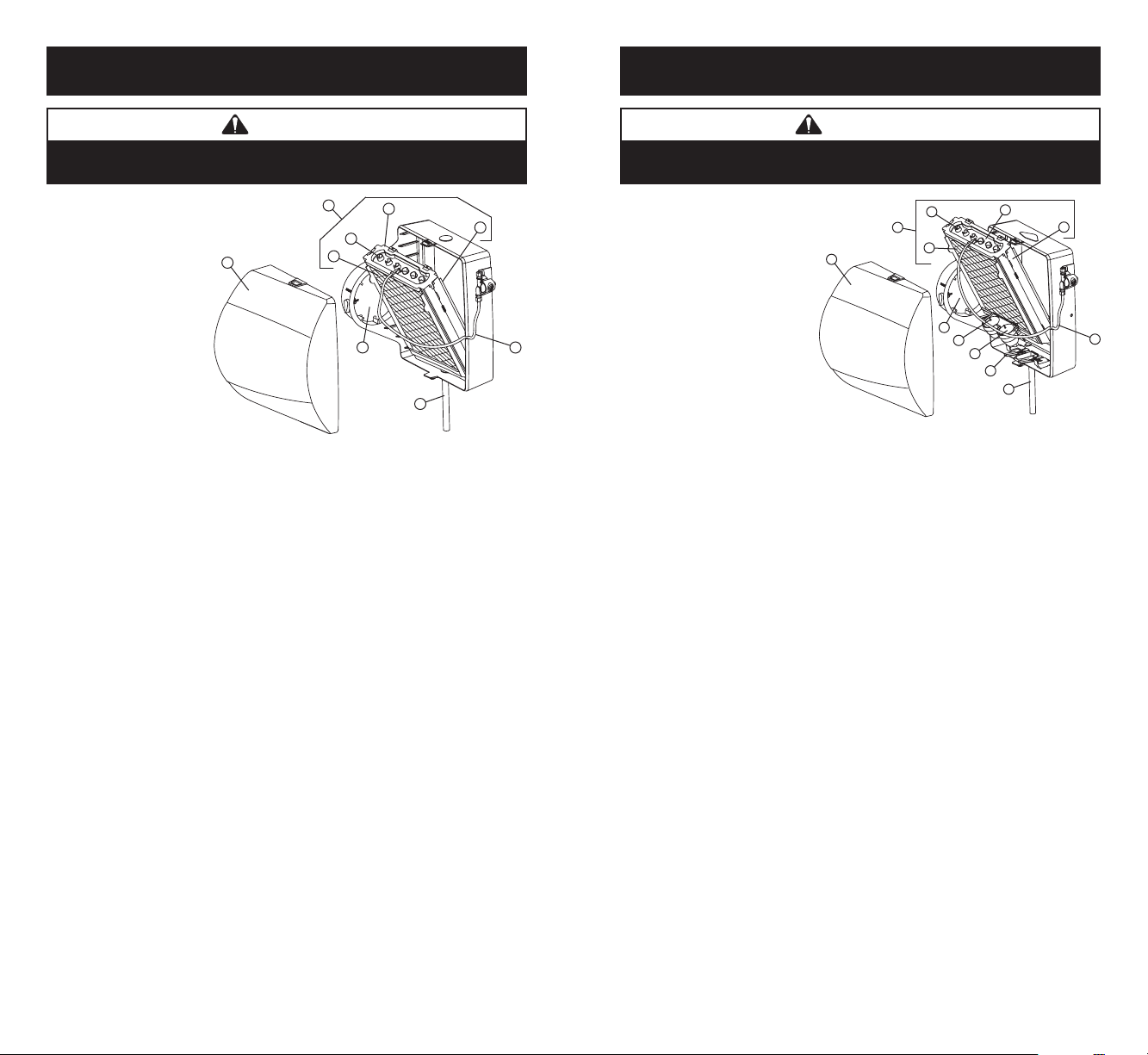
1. Front Cover
2. Feed Tube
3. Integral Bypass Damper
4. Evaporative Assembly
5. Distribution Tray
6. “V” Notches
7. Humidifier Pad
8. Scale Control Insert
9. Drain Line
CAUTION
Sudden operation may cause personal injury or property damage.
Turn Humidifier Control to “OFF” or lowest setting before servicing.
90-1173
MAINTENANCE INSTRUCTIONS FOR
WATER SAVER HUMIDIFIER
1. Note Humidifier Control setting and turn dial to the “OFF” position.
2. Turn off water supply. Turn the integral bypass damper (3) to the “SUMMER” position.
3. Press the tabs in the latches on the top and bottom of front cover (1) and pull cover off base with
both hands.
4. Carefully pull the plastic feed tube (2) out of the distribution tray (5) at the top of the evaporative
assembly (4). Tip the evaporative assembly forward and lift it out of the humidifier. Do not tip the
evaporative assembly more than needed to clear the housing to avoid over‑bending the water level
sensor assembly (12).
5. Unsnap the distribution tray (5) from the scale control insert (8). Lightly scrape out or brush off any
mineral deposits, being careful not to stretch or loosen the synthetic fabric liner. Soaking the tray in
vinegar or a lime‑removing agent is helpful when trying to remove stubborn mineral deposits.
6. Slide the used Humidifier Pad (7) out of the scale control insert/float chamber and dispose of it.
7. Remove the float cover (10) and inspect the floats (11) and float chamber for mineral build‑up.
Remove deposits as needed from floats, float chamber and scale control insert. Wash the parts with
a disinfecting cleaner. Reassemble the floats and float cover. Make sure stems of both floats extend
through openings in float cover and that floats move freely up and down.
8. Inspect the plastic feed tube (2) by gently flexing it and looking for cracks or signs of wear. Replace
tube if it is cracked, brittle, or has been damaged.
9. Slide a new Humidifier Pad Part No. P110‑4545 (7) into the scale control insert/float chamber (8).
Snap the distribution tray (5) back on the scale control insert (8). Note: using non‑recommended
pads may result in leaks or improper operation.
10. Reinstall the evaporative assembly (4) into the humidifier. Take care not to over‑bend the water level
sensor assembly. Push the top of the evaporative assembly firmly back until it snaps into place.
11. Push the end of the feed tube back firmly into the distribution tray. Replace the front cover.
12. Under normal operation the overflow drain line (9) will never have water in it. However, inspect it for
mineral deposits and replace if necessary. Make sure the drain line has a constant downward slope
and is not flattened or blocked.
13. Turn on the water supply. Return integral bypass damper to appropriate position.
14. Check system operation:
Manual Humidifier Control: With the furnace blower operating and the furnace calling for heat,
turn up Control and check system operation.
Humiditrac
™
Humidifier Control: (Automatic or Manual mode) Check system operation and
reset Change Humidifier Pad indicator by setting the knob to “Test/Reset”. With furnace blower
operating and furnace calling for heat, humidifier will operate for one minute. DO NOT LEAVE IN
TEST MODE AS HUMIDIFIER WILL NOT OPERATE.
15. Set Humidifier Control to its original position.
1. Front Cover
2. Feed Tube
3. Integral Bypass Damper
4. Evaporative Assembly
5. Distribution Tray
6. “V” Notches
7. Humidifier Pad
8. Scale Control Insert /Float
Chamber
9. Overflow Drain Line
10. Float Cover
11. Float
12. Water Level Sensor Assembly
CAUTION
Sudden operation may cause personal injury or property damage.
Turn Humidifier Control to “OFF” or lowest setting before servicing.
9
12
6
11
10
3
7
8
5
2
1
4
90-1077
Loading ...
Loading ...