Loading ...
Loading ...
Loading ...
page 6
7. Canopy Assembly.
This fan is remote control adaptable (remote control
sold separately). Note: Only remote controls approved
for WET locations can be used with this fan.
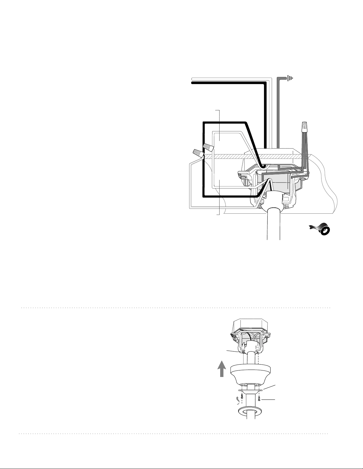
6. Wiring.
CAUTION: Be sure outlet box is properly grounded
and that a ground wire (GREEN or Bare) is present.
Make sure all electrical connections comply with
Local Codes or Ordinances and the National Electrical
Code. If you are unfamiliar with electrical wiring or if
the house/building wires are different colors than
those referred to in the instructions below, please use
a qualified electrician.
Note: Excess lead wire length from the fan can be cut
to the desired length and then stripped.
WARNING: If using this fan in a WET or DAMP
location, this fan must be connected to a supply
circuit that is protected by a Ground Fault Circuit
Interrupter (GFCI) to reduce the risk of personal
injury, electrical shock or death.
When fan is secured in place on the hanging
bracket, electrical wiring can be made as follows:
Connect BLACK and BLUE wires from fan to
BLACK wire from ceiling with wire connector
provided.
Connect WHITE wire from fan to WHITE wire from
ceiling with wire connector provided.
Connect all GROUND (GREEN) wires together
from fan to BARE/GREEN wire from ceiling with
wire connector provided.
If you intend to control the fan light with a
separate light switch connect BLUE wire from fan
to the BLACK (or RED) supply from the
independent switch.
* Wrap each wire connector separately with
electrical tape as an extra safety measure.
black supply wire
white supply wire
ground
(green or bare)
*
black
black
white
white
blue
ground
(green
or bare)
from ceiling
from fan
canopy
hanging bracket
screw
screw
canopy cover
Remove 2 screws on underside of hanging bracket.
Lift canopy to hanging bracket. Align holes in
canopy with holes in hanging bracket. While holding
canopy in place, slide anti-sway adapter up to
canopy. Align holes in anti-sway adapter with holes
in bottom of canopy and then re-insert the screws
that were previously removed. Tighten both screws
securely.
Slide canopy cover up to anti-sway adapter, aligning
rounded part of slotted holes in canopy cover with
screw heads in bottom of anti-sway adapter. Turn
canopy cover to the right (clockwise) until it stops.
anti-sway adapter
Loading ...
Loading ...
Loading ...