
Owner's Manual
I(RRFTSMRH°I
23.0 HP
ELECTRIC START
48" MOWER
AUTOMATIC
GARDEN TRACTOR
Model No.
917.275020
• Safety
• Assembly
• Operation
• Maintenance
• Repair Parts
CAUTION:
Read and follow all Safety
Rules and Instructions before
operating this equipment.
For answers to your questions
about this product, Calh
1-800-659-5917
Sears Craftsman Help Line
5 am - 5 pro, Mon- Sat
Sears, Roebuck and Co., Hoffman Estates, II 60179
Visit our Craftsman website:www.sears.com/craftsman

Warranty ............................................... 2
Safety Rules ......................................... 3
Product Specifications .......................... 6
Assembly .............................................. 8
Operation ............................................ 13
Maintenance Schedule ...................... 20
Maintenance ....................................... 20
Service and Adjustments.................... 24
Storage ............................................... 32
Troubleshooting ................................. 33
Repair Parts........................................ 38
Parts Ordedng ..................... Back Cover
LIMITED TWO YEAR WARRANTY ON CRAFTSMAN RIDING EQUIPMENT PARTS
For two (2) years from the date of purchase, if this Craftsman Riding Equipment is
maintained, lubricated and tuned up according to the instructions in the owner's
manual, Sears will repair or replace, free of charge, any parts found to be defective in
matedal or workmanship. Warranty service is available free of charge by returning
your Craftsman riding equipment to your nearest Sears Service Center. In-home
warranty service is available but a trip charge will apply. This warranty applies only
while this product is in the United States.
This Warranty does not cover:
• Expendable items which become worn during normal use, suchas blades, spark
plugs, air cleaners, belts and oil filters.
• Tire replacement or repair caused by punctures from outside objects, such as nails,
thorns, stumps, or glass.
• Repairs necessary because of operator abuse, includingbut notlimited to, damage
caused by towing objects beyond the capability of the dding equipment, impacting
objects that bend the frame or crankshaft, or over speeding the engine.
• Repairs necessary because of operator negligence, including but not limited to,
electrical and mechanical damage caused by imp_'operstorage, failure to use the
proper grade and amount of engine oil,failure to keep the deck clear offlammable
debds, or the failure to maintain the equipment according to the instructions
contained in the owner's manual.
• Engine (fuel system) cleaning or repairs caused by fuel determined to be contami-
nated or oxidized (stale). In general, fuel should be used within thirty(30) days of its
purchase date.
• Riding equipment used for commercial or rental purposes. A product is "used for
commerdal purpose" if is used for any purpose other than singlefamily household
dwellingsor in usage where profit is made.
LIMITED 90 DAY WARRANTY ON BATTERY
For ninety (90) days from date of purchase, if any battery included with this riding
equipment proves defective in material or workmanship and our testing determines
the battery will not hold a charge, Sears will replace the battery at no charge. War-
renty service is available free of charge by returning your Craftsman ddleg equipment
to your nearest Sears Service Center. In-home warranty service is available but a trip
charge will apply. This warranty applies only while this product is in the United States.
TO LOCATE THE NEAREST SEARS SERVICE CENTER ORTO SCHEDULE IN-
HOME WARRANTY SERVICE, SIMPLY CONTACT SEARS AT 1-800-4-MY-HOME
This Warranty gives you specificlegal rights, and you may also have other rights
whichmay vary from state to state.
Sears, Roebuck and Co., D/817 WA, Hoffman Estates, IL 60179

IMPORTANT: This cuttingmachine is capable of amputating hands and feet and
throwingobjects. Failure to observe the followingsafety instructionscould result in
serious injuryor death.
I. GENERAL OPERATION
• Read, understand, and follow all
instructionsin the manual and on the
machine before starting.
• Only allow responsible adults, who are
familiar with the instructions,to operate
the machine.
• Clear the area of objects such as
rocks,toys,wire, etc., whichcould be
picked up and thrown by the blade.
• Be sure the area isclear of other
people before mowing. Stop machine
ff anyone enters the area.
• Never sam] passengers.
• Do not mow in reverse unless abso-
lutely necessary. Always look down
and behind before and while backing.
• Be aware of the mower discharge
direction and do not point itat anyone.
Do not operate the mower without
either the entire grass catcher or the
guard in place.
• Slow down before turning.
• Never leave a running machine
unattended. Always turn off blades, set
parking brake, stop engine, and
remove keys before dismounting.
• Turn off blades when not mowing.
• Stop engine before removing grass
catcher or unclogging chute.
• Mow only in daylightor good artificial
tight.
• Do not operate the machine while
under the influence of alcohol or drugs.
• Watch for traffic when operating near or
crossing roadways.
• Use extra care when loading or
unloading the machine intoa trailer or
truck.
• Data indicates that operators, age 60
years and above, are involvedin a
large percentage of riding mower-
related injudes. These operators
should evaluate their ability to operate
the ddieg mower safely enough to
protect themselves and others from
sedous injury.
• Keep machine free of grass, leaves or
other debds build-up which san touch
hotexhaust / engine parts and bum.
Do not allow the mower deck to plow
leaves or other debris which can cause
build-up to occur.
Clean any oil or fuel spillage before
operatingor storingthe machine.
Allow machine to cool before storage.
II. SLOPE OPERATION
Slopes are a majorfactor related toloss-of-
control and tipover accidents, which can
result in severe injury or death. All slopes
require extra caution. Ifyou cannot backup
the slope or if youfeel uneasy on it, do not
mow it,
DO:
• Mow up and down slopes, not across.
• Remove obstacles suchas rocks, tree
limbs,etc.
• Watch for holes, ruts, or bumps.
Uneven terrain could overturn the
machine. Taftgrass can hide ob-
stacles.
• Use slow speed. Choose a low gear
so that you will nothave to stop or shift
while on the slope.
• Follow the manufacturer's recommen-
datlens for wheel weights or counter-
weights to improve stability.
• Use extra care with grass catchers or
other attachments. These san change
the stabilityof the machine.
• Keep all movement on the slopes slow
and gradual Do not make sudden
changes in speed or direction.
• Avoid startingor stoppingon a slope. If
tires lose traction, disengage the
blades and proceed slowly straight
down the slope.
DO NOT:
• Do not turn on slopes unless neces-
sary, and then, turn slowly and gradu-
ally downhill, if possible.
• Do not mow near drop-offs, ditches, or
embankments. The mower could
suddenly turnover if a wheel is over
the edge ofa cliffor ditch, or if an edge
saves in.
• Do not mow on wet grass. Reduced
traction could cause sliding.
• Do not try to stabilize the machine by
putting your foot on the ground.
• Do not use grass catcher on steep
slopes.
3
IlL CHILDREN
Tragicaccidents can occur if the operator
is not alert to the presence of children.
Childrenare often attracted tothe
machineand the mowing activity. Never
assume that children will remain where
you last saw them.
• Keep chit{ben out of the mowing area
and under the watchful care of another
responsible adult.
• Be alert and turn machine off if children
enterthe area.
• Before and when backing, look behind
and down for small children.
• Never carry children. They may fall off
and be seriously injured or interfere
with safe machine operation.
• Never allow children to operate the
machine.
• Use extra care wben approaching blind
comers, shrubs, trees, or other objects
that may obscure vision.
IV. SERVICE
• Use extra care in handling gasoline
and other fuels. They are flammable
and vapors are explosive.
- Use only an approved container.
- Never remove gas cap or add fuel
with the engine running. Allow
engine to cool before refueling. Do
notsmoke.
-Never refuel the machine indoors
-Never store the machine or fuel
container inside where there is a_
open flame, such as a water heat
• Never run a machine inside a closq
area.
• Keep nuts and bolts, especially bl_
attachment bolts, tightand keep
equipment in good condition.
• Never tamper with safety devices.
Check their proper operation regul
• Keep machine free ofgrass, leave,,
other debds build-up. Clean oil or
spillage. Allow machine to cool b_
stodng.
• Stop and inspect the equipment if !
stdke an object. Repair, ifnecessz
before restarting.
• Never make adjustments or repair,'
with the engine running.
• Grass catchercomponents are sul
to wear, damage, and deterioratioi
which could expose moving parts
allow objects to be thrown. Frequ_
check components and replace wi
manufacturer'srecommended pad
when necessary.
• Mower blades are sharp and can (
Wrap the blade(s) or wear gloves,
use extra caution when servicingt
• Check brake operation frequently.
Adjust and service as required.
• Be sure the area is clear ofother
people before mowing. Stop machine if
anyone enters the area.
• Never carry passengers or children
even with the blades off.
• Do not mow in reverse unless abso-
lutely necessary. Always look down
and behind before and while backing.
• Never carry children. They may fall off
and be sedously injured or interfere
with safe machine operation.
• Keep children out of the mowing area
and under the watchful care of another
responsible adult.
• Be alert and turn machine off ifchi
enter the area.
• Before and when hacking, look be
and down for small children.
• Mow up and down slopes (15° Ma
not across.
• Remove obstacles such as rocks,
limbs,etc,
• Watch for holes, ruts, orbumps.
Uneven terrain could overturn the
machine. Tall grass can hide obst
4
• Use slow speed. Choose a low gear so
that you willnot have tostop or shift
while on the slope.
• Avoid startingor stoppingon a slope. If
tires lose traction, disengage the
blades and proceed slowly straight
down the slope.
• If machine stops while going uphill,
disengage blades, shift into reverse
and back down slowly.
• Do not turn on slopes unless neces-
.sary,and then, turn slowly and gradu-
ally downhill,if possible.
,_Look for this symbol to point out
importantsafety precautions. It means
CAUTION!!f BECOMEALERTII! YOUR
SAFETY IS INVOLVED.
CAUTION: In order to prevent
accidental starting when setting up,
transporting, adjusting or making repairs,
always disconnect spark plug wire end
place wire where it cannot contact spark
plug.
,_ CAUTION: Do not ccast down e hill
in neutral, you may lose control of the
tractor.
,_ CAUTION: Tow onlythe attachments
that are recommended by and comply
with specificationsof the manufacturer of
your tractor. Use common sense when
towing. Operate only at the lowest
possiblespeed when on a slope. Too
heavy of a load, while on a slope, is
dangerous. Tires can lose tractionwith
the ground and cause you to lose control
of yourtractor.
_I, WARNING: Engine exhaust, some of
its constituents,and certain vehicle
components contain or emit chemicals
known to the State of California to cause
cancer and birth defects or other repro-
ductive harm.
_WARNING: Battery posts, terminals
and related accessories contain lead and
lead compounds, chemicals known to the
State of California to cause cancer and
birthdefects or other reproductive harm.
Wash hands after handling.
5

PRODUCTSPECIFICATIONS
GASOLINE
CAPACITY
AND TYPE:
OiL TYPE
API-SF-SJ):
OIL CAPACITY:
3.5 GALLONS
UNLEADED
REGULAR
SAE tOW30
(ABOVE 32°F)
SAE 5W-30
(BELOW 32°F)
WlFILTER: 4,5PINTS
W/O FILTER:4.0PINTS
SPARK PLUG: CHAMPION
IGAP: .030") RC_2YC
GROUND FORWARD: 5.8
SPEED(MPH): REVERSE: 2.1
TIRE FRONT: 14 PSi
PRESSURE: REAR: 10 PSi
CHARGING tSAMPS @3600RPM
SYSTEM:
BATTERY: AMP/HR: 35
MIN. CCA: 280
CASE SIZE:U1R
BLADE BOLT 45-55 FT. LBS
TORQUE:
CONGRATULATIONS on your purchase
of a new trsctor. It has been designed,
engineered and manufactured to give
you the best possible dependability and
performance.
Should you experience any problem you
cannot easily remedy, please contact a
Sears or other qualified service center.
We have competent, well-trained techni.
clans and the proper toolsto service or
repair this tractor,
Please road and retain this manual. The
instructionswill enable you to assemble
and maintain your tractorproperly.
Always observe the "SAFETY RULES".
REPAIR AGREEMENT
A Repair Agreement is available on this
product. Contact your nearest Sears
store for details.
CUSTOMER RESPONSIBILITIES
• Read and observe the safety rules.
• Follow a regular schedule in maintair
ing. caring for and using your !ractor.
• Follow the instructionsunder Mainte
nance" and "Storage" sections of this
owner's manual.
_IWARNING: This tractor is equippec
with an internal combustion engine and
should not be used on or near any
unimproved forest-covered, brush-
covered or grass-coverod land unless tJ
engine's exhaust system is equipped w
a spark arrester meeting applicable Ioc.
or state laws (if any). If a spark arrester
used, it should be maintained Jneffecfi',
working order by the operator.
In the state of California the above is
reqairod by law (Sectlan 4442 of the
California Public Resources Code).
Other states may have similarlaws.
Federal laws apply on federal lands. A
spark arrester for the muffler is availabl
through your nearest Sears service
center (See REPAIR PARTS section of
this manual).
6
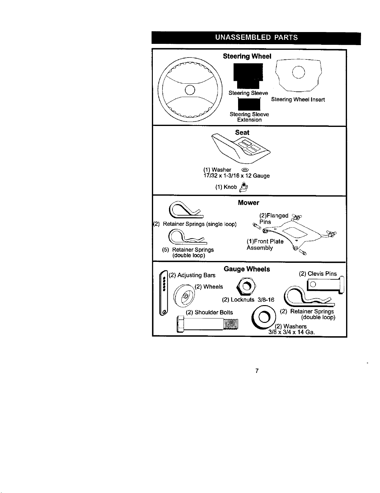
Steering Wheel
Steering Sleeve
SteeringWheelInsert
Steering Sleeve
Extension
Seat
(1) Washer
17/32 x 1-3/16 x 12 Gauge
(1) Knob
Mower
12) Retainer Springs (single loop)
(5) Retainer Springs
(double loop)
(2)Flanged
_Pins
(1)Front Plate
Assembly
Gauge Wheels
(2) AdjustingBars (2) Clevis Pins
_(2) Wheels _
(2) Locknuts 3/8-16
_"_ (2) Retainer Springs
2) Shoulder Bolts _k (_) (double loop)
(2) Washers
3/8 x 3/4 x 14 Ga.
7
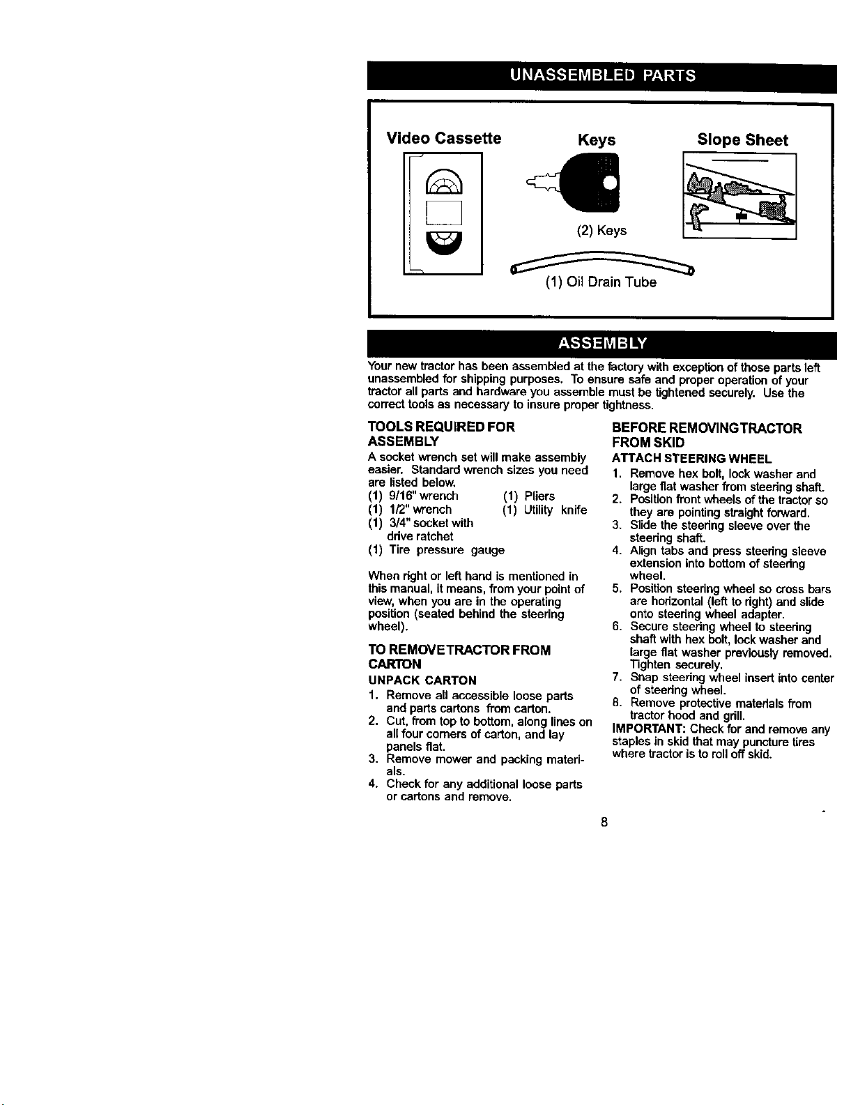
Video Cassette
Keys Slope Sheet
(1) Oil Drain Tube
Your new tractor has been assembled at the factory with exceptionof those parts left
unassembled for shipping purposes. To ensure safe and proper operaticn of your
tractor all parts and hardware you assemble must be tightened securely. Use the
correct tools as necessary to insure proper tightness.
TOOLS REQUIRED FOR
ASSEMBLY
A socket wrench set will make assembly
easier. Standard wrench sizes you need
are listed below.
(1) 9/16"wrench (1) Pliers
(1) 1/2"wrench (1) Utility knife
(1) 3/4" socket with
ddve ratchet
(1) Tire pressure gauge
When dght or left hand is mentioned in
this manual, it means, from your point of
view,when you are in the operating
position (seated behind the steering
wheel).
TO REMOVETRACTOR FROM
CARTON
UNPACK CARTON
1. Remove all accessible loose parts
and parts cartons from carton.
2. Cut, from top to bottom, along lines on
all four comers of carton, and lay
panels fiat.
3. Remove mower and packing materi-
als.
4. Check for any additional loose parts
or cartons and remove.
BEFORE REMOVINGTRACTOR
FROM SKID
ATTACH STEERING WHEEL
1. Remove hex bolt, lockwasher and
large fiat washer from steeringshaft.
2. Positionfront wheels ofthe tractor so
they are pointingstraight forward.
3. Slide the steering sleeve over the
steedng shaft.
4. Align tabs and press steering sleeve
extension into bottom of steering
wheel.
5. Positionsteering wheel so crossbars
are horizontal (left to right) and slide
onto steedng wheel adapter.
6. Secure steedng wheel to steedng
shaft with hex bolt, leekwasher and
large fiat washer previouslyremoved.
Tighten securely,
7. Snap steering wheel insert intocenter
of steedng wheel.
8. Remove protective materials from
tractor hood and gdll.
IMPORTANT: Check for and remove any
staples in skid that may puncture tires
where tractor isto roll off skid.
8
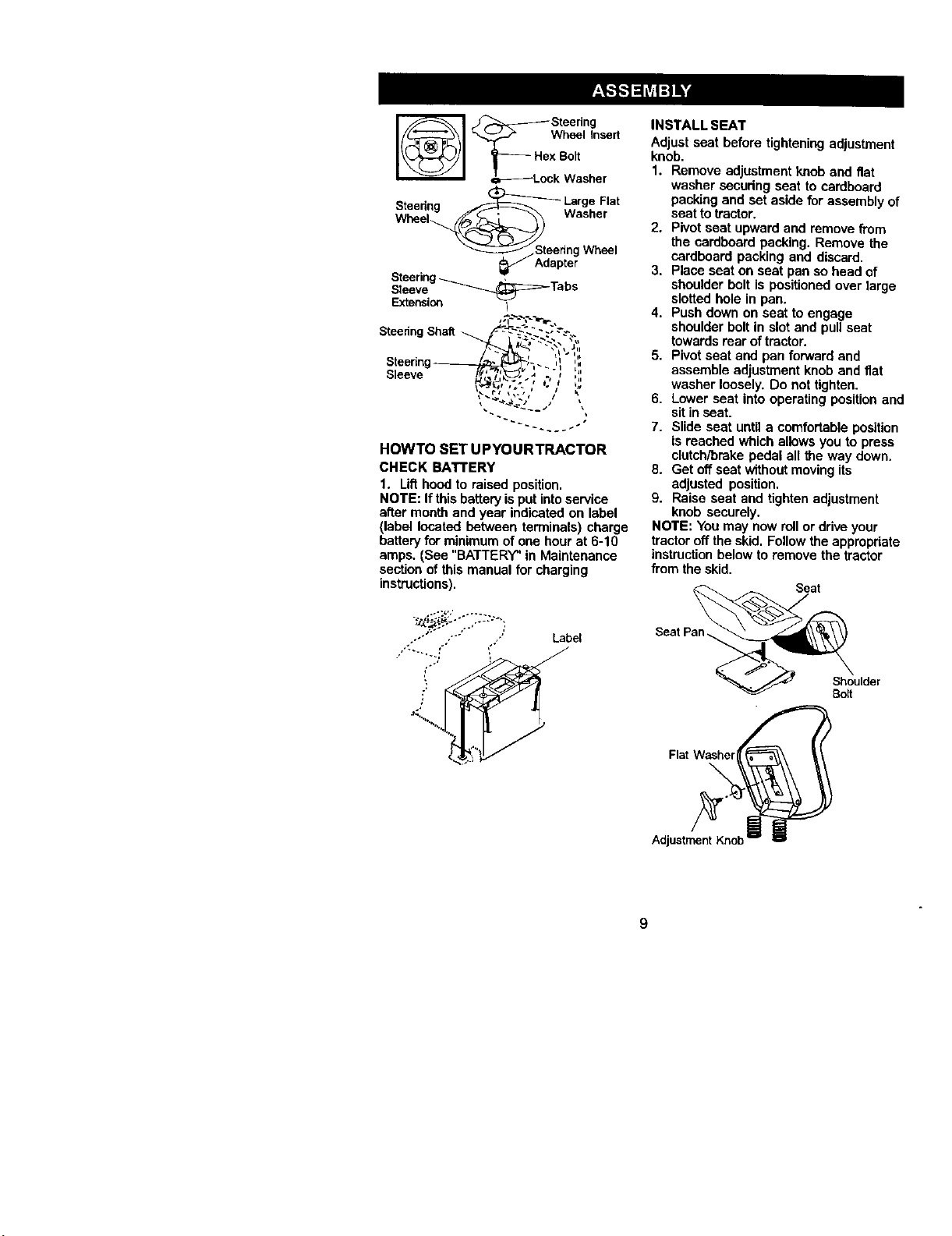
x Bolt
_-d--Lock Washer
Steedng _ LargeFlat
Wheel__ Washer
_/Steerlng Wheel
_J Adapter
Steering_ ,
Sleeve _....._:=_- Tabs
Extension I
Steering
Shaft
Steermg_-_',_-. ,_ ',,,
seeve -,,' ",',
HOWTO SET UPYOURTRACTOR
CHECK BATTERY
1. Lifthoed to raised position.
NOTE: If thisbatteryis put intoservice
after month and year indicated on label
(label located between terminals) charge
battery for minimum of one hour at 6-10
amp& (See "BATTERY" in Maintenance
section of this manual for charging
instructions),
.}._£{g:..-..._. _-,,.
'_" "" " Label
• _';::_
INSTALL SEAT
Adjust seat before tightening adjustment
knob•
1. Remove adjustment knob and flat
washer securing seat to cardboard
packing and set aside for assembly of
seat totractor.
2. Pivot seat upward end remove from
the cardboard packing. Remove the
cardboard packing and discard.
3. Place seat on seat pan so head of
shoulder bolt is positioned over large
slotted hole in pan.
4. Push down on seat to engage
shoulder belt in slot and pull seat
towards rear of tractor.
5. Pivot seat and pan forward and
assemble adjustment knob and flat
washer loosely. Do not tighten.
6. Lower seat into operating position and
sit in seat.
7. Slide seat until a comfortable position
is reached which allows you to press
clutch/brake pedal all the way down.
8. Get off seat withoutmovingits
adjusted position.
9. Raise seat and tighten ad)ustment
knob securely.
NOTE: You may now rollor drive your
tractor off the skid. Follow the appropriate
instructionbelow to remove the tractor
from the skid.
Seat
SeatP_
_'_. _ Shoulder
Bolt
FlatWasher_ _
Adjustm_n_tK'_ncb_

TOROLLTRACTOROFFSKiD(See
Operationsectionforlocationand
functionofcontrols)
1. Pressliftleverplungerandraise
attachment _lftlever to its highest
position.
2. Release parking brake by depressing
brake pedal.
3. Place freewheel control in freewheel-
ing position to disengage transmis-
sion(See =TOTRANSPORT" in the
Operation section of this manual).
4. Roll tractorforward off skid.
TO DRIVETRACTOR OFF SKID (See
Operation section for location and
function of controls)
,_WARNING: Before starting, read, .
understand and follow a_llestructtons in
the Operation section of this manual. Be
sure tractor is in a well-ventilated area. Be
sere the area in front of tractor isclear of
other people and objects.
1. Be sure all the above assembly steps
have been completed.
2. Check engine oil level and flUfuel
tank with gasoline.
3. Place freewheel control in "transmis-
sion engaged" position.
4. Sit on seat in operating position,
depress brake pedal and set the
parking brake.
5. Press liftlever plunger and raise
attachment liftlever to its highest
position.
6. Startthe engine. After engine has
started, move throttle control to idle
position.
7. Release parking brake.
8. Slowly move the motion control lever
forward and slowly ddve tractor off
skid.
g. Apply brake tostop tractor and set
parking brake.
10.Turn Ignition key to "OFF" positien.
Continue with the instructionsthat follow.
ASSEMBLE GAUGE WHEELST,
MOWER DECK
The gauge wheels are designed to,
the mower deck in proper position w
operating mower. Be sure theyare
propedy adjusted to ensure optimun
mower performance.
1. Slide gauge wheel bar down int¢
bracket channel, Be sure that gal
wheel bar aligning holes are on t
Assemble gauge wheels as sho'+
using shoulder bolts, 3/8 washer.
3/8-16 center lecknuts and tighte
securely.
2. For ease of mower totractor ass_
bly, raise gauge wheels to hlghe:
positionand retain with clevis pit
and spdng retainers.
NOTE: Adjustgauge wheels before
operating mower. See %0 ADJUST
GAUGE WHEELS" in the Operation
section of this manual.
Retainer
Pin_
10
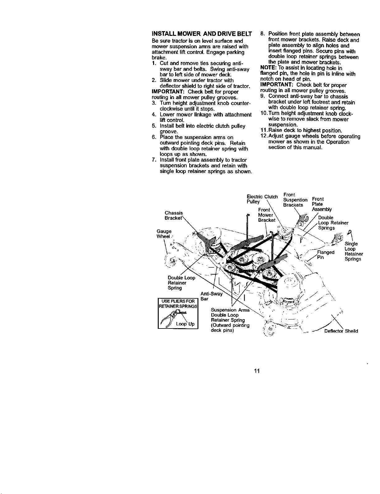
INSTALL MOWER AND DRIVE BELT
Be sure tractoris on level surface and
mower suspension arms are raised with
attachment liftcontrol. Engage parking
brake.
1. Cutand remove ties securing anti-
sway bar and belts. Swing anti-sway
barto left side of mower deck.
2. Slide mower under tractor with
deflector shield to fight side of tractor.
IMPORTANT: Check belt for proper
routingin all mower pulley grooves.
3. Turn height adjustment knob counter-
clockwiseuntil it stops.
4. Lower mower linkage with attachment
liftcontrol.
5. Install belt intoelectric clutchpulley
groove.
6. Place the suspensionarms on
outward pointingdeck pins. Retain
with double loop retainer spring with
loops up as shown.
7. Installfront plate assembly to tractor
suspensionbrackets and retain with
single loop retainer springs as shown•
8. Positionfront plate assembly between
front mower brackets. Raise deck and
plate assembly to align holes and
insert flanged pins. Secure pinswith
double loop retainer springs between
the plate and mower brackets.
NOTE: To assist in locatinghole in
flanged pin, the hole in pin is inlinewith
notch on head of pin.
IMPORTANT: Check belt for proper
routingin all mower pulley grooves.
9. Connect anti-sway bar to chassis
bracket under leftfootrest and retain
with double loop retainer spring.
10.Turn height adjustment knob clock-
wise to remove slack from mower
suspension•
11.Raise deck to highest position.
12.Adjust gauge wheels before operating
mower as shown in the Operation
section of this manual•
Chassis
Gauge
Wheel .-
Double Loop
Retainer
Spring
USE PLIERS FOR
RETAINER SPRINGS
Electric Clutch Front
Pulley Suspention Front
Brackets Plate
Assembly
.Loop Retainer
Anti-Sway
Bar
Double Loop
Retainer Spring
(Outward pointing
deck pins)
Loop
Retainer
Springs
11

CHECK TIRE PRESSURE
The fires on your tractor were ovefinflated
at the factory for shipping purposes.
Correct tire pressure is importantfor best
cutting performance.
• Reduce tire pressure to PSI shown in
"PRODUCT SPECIFICATIONS" section
of this manual.
CHECK MOWER LEVELNESS
For best cuttingresults, mower should be
propedy leveled. See "TO LEVEL
MOWER HOUSING" in the Service and
Adjustments section of this manual.
CHECK FOR PROPER POSITION OF
ALL BELTS
See the figuresthat are shown for
replacing motion, mower drive, and
mower blade drive belts in the Service
and Adjustmentssection ofthis manual.
Verify that the beltsare routed correctly.
V'CHECKMST
Before you operate and enjoy your new
tractor,we wishto assure thatyou receive
the best performance and satisfaction
from this Quality Product.
Please review the following checklist:
,/All assembly instructionshave been
completed.
,/No remaining loose parts in carton.
,/Battery is preperly prepared and
charged. (Minimum 1 hourat 6 amps).
,/Seat is adjusted comfortablyand
tightened securely.
,/All tires are properly inflated. (For
shipping purposes, the tires were
ovednflated at the factory).
,/Be sure mower deck is properly leveled
side-to-side/front-to-rear for best cutting
results. (Tires must be propedy inflated
for leveling).
,/Check mower and ddve belts. Be sure
they are routed properly around pulleys
and inside all belt keepers.
,/Check wiring. See that all connecUons
are still secure and wires are prepedy
clamped.
,/Before ddving tractor, be sure free-
wheel control is in drive position.
While learning how to use your tractor,
pay extra attention to the following
important items:
,/ Engine oilis at proper level.
,/Fuel tank isfilled withfresh, clean,
regular unleaded gasoline.
,/Become familiar with all controls- their
location and function. Operate them
before you start the engine.
,/Be sure brake system is in safe
operating condition.
,/It is important to purge the transmission
before operating your tractor for the first
time. Follow proper starting and
transmission purging instructions (See
"TO START ENGINE" and "PURGE
TRANSMISSION" in the Operation
section of this manual).
12
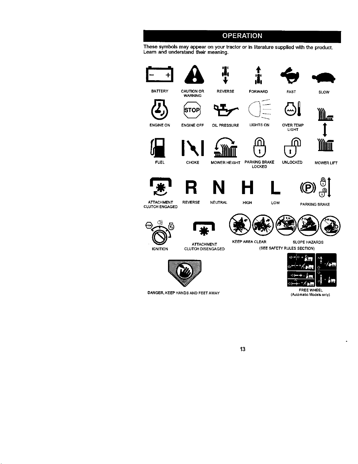
These symbols may appear on your tractor or in literature supplied with the product.
Learn and understand their meaning.
& =.
BATTERY CAUTION OR REVERSE FORWARD FAST SLOW
WARNING
ENGINE ON ENGINE OFF OIL PRESSURE LIGHTS ON OVER TEMP
LIGHT
1
FUEL CHOKE MOWER HEIGHT PARKING BRAKE UNLOCKED
LOCKED
MOWER LIFT
_r_t R N H L
ATTACHMENT REVERSE NEUTRAL HIGH LOW
CLUTCH ENGAGED
PARKING BRAKE
ATTACHMENT KEEP AREA CLEAR SLOPE HAZARDS
IGNmON CLUTCH DISENGAGED
DANGER, KEEP HANDS AND FEET AWAY
(SEE SAFETY RULES SECTION)
FREE WHEEL
(AutomaticModels only)
13

KNOWYOURTRACTOR
READ THIS OWNER'S MANUAL AND SAFETY RULES BEFORE OPERATING
YOUR TRACTOR
Compare the illustrationswith your tractor to familiarize yourself with the locations of
various controlsand adjustments. Save this manual for future reference.
Choke
Control
Throttle
Ammeter Ignition
Switch
Light
Switch
Attachment
Clutch
Lift
Plunger
Motion Ddve
Belt Tension
Alachment
Lift Lever
Parking Brake
Lever
Height
Adjustment
Knob _
Free
Wheel
Control
n Control
Lever
Our tractorsconform to the safety standards of the Amedcan National Standards
Institute.
ATTACHMENT CLUTCH SWITCH -
Used to engage the mower blades, or
other attachments mounted to your
tractor.
UGHT SWITCH - Turns the headlightson
and off.
THROTTLE CONTROL - Used tocontrol
engine speed.
BRAKE PEDAL - Used for brakingthe
tractor and starting the engine.
CHOKE CONTROL - Used when starting
a cold engine.
HEIGHT ADJUSTMENT KNOB - Used to
adjust the mower cuttingheight.
IGNITION SWITCH - Used for starting
and stoppingthe engine.
AI"rACHMENTUFT LEVER - Usedto raise
and lowerthe mowerdeckorotherattach-
meritsmountedto yourtractor.
LIFT LEVER PLUNGER - Used to
release attachment lift lever when
changing its position.
AMMETER - Indicatescharging (+) or
discharging (-) of battery.
PARKING BRAKE LEVER - Locks brake
pedal intothe brake position.
MOTION CONTROL LEVER - Selects the
speed and directionof tractor.
FREEWHEEL CONTROL - Disengages
transmissionfor pushing or slowly
towing the tractorwith the engine off.
MOTION DRIVE BELTTENSION
HANDLE-Used when changing motion
ddve belt and, if necessary,starting
engine under extremely cold conditions.
14
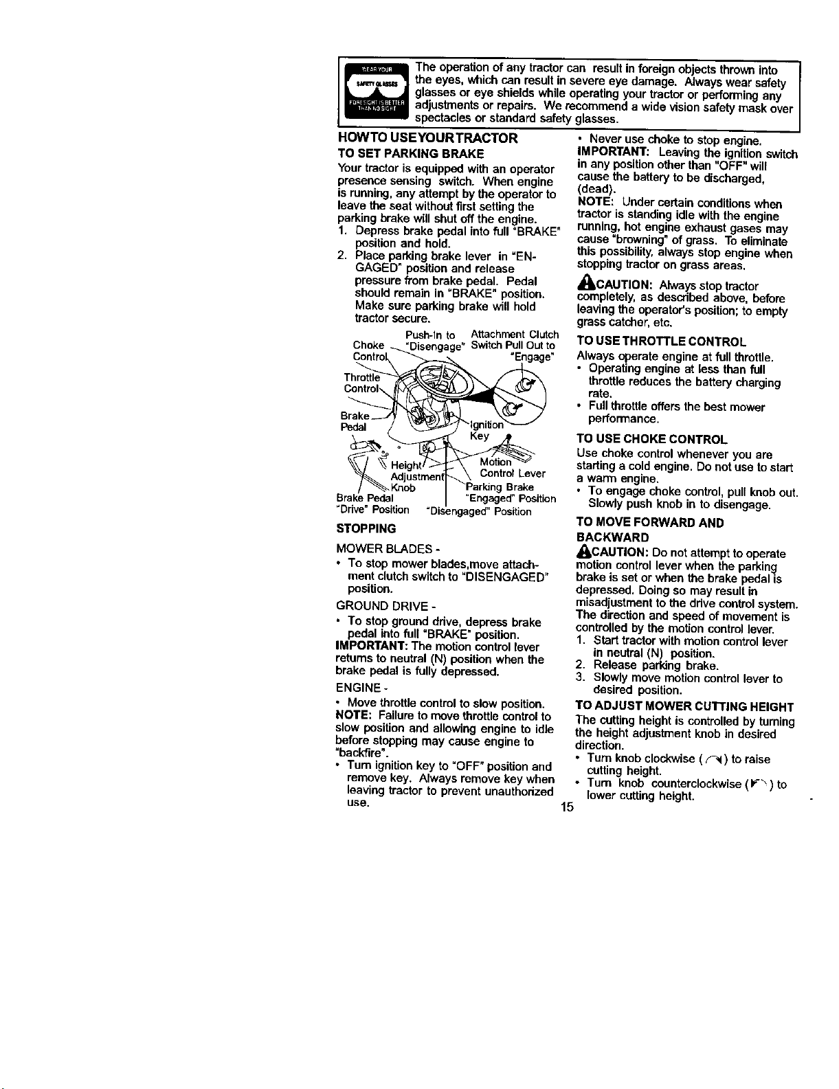
The operation of any tractor can result in foreign objects thrown into
u_=,=_ the eyes, whichcan result in severe eye damage. Always wear safety
glasses or eye shields while operating your tractor or performing any
adiustments or repairs. We recommend a wide vision safety mask over
spectacles or standard safety glasses.
HOWTO USEYOURTRACTOR
TO SET PARKING BRAKE
Your tractor is equipped with an operator
presence sensing switch. When engine
is running,any attempt by the operatorto
leave the seat withoutfirst setting the
parking brake will shut off the engine.
1. Depress brake pedal intofull "BRAKE"
position and hold.
2. Place parking brake lever in "EN-
GAGED" positionand release
pressure from brake pedal. Pedal
should remain in =BRAKE" position.
Make sure parking brake will hold
tractor secure.
Push-Into Attachment Clutch
Choke _._"Disengage" SwitchPullOutto
Control _< =Engage"
Throttle
Brake
--,_.T,:.?.-2___,T_\ ControlLever
P_]jus[rnen
BraiSeP__edaL I "Engaged"Position
"Drive"Posit_m7 "Disengaged"Posltion
STOPPING
MOWER BLADES -
• "re stop mower blades,move attach-
ment clutch switch to "DISENGAGED"
position.
GROUND DRIVE -
• To stop ground drive, depress brake
pedal into full "BRAKE" position.
IMPORTANT: The motion control lever
returnsto neutral (N) position when the
brake pedal is fully depressed.
ENGINE -
• Move throttle control to slow position.
NOTE: Failure to move throttle controlto
slow position and allowing engine to idle
before stopping may cause engine to
"backfire".
• Turn ignition key to =OFF" positionand
remove key. Always remove key when
leaving tractor to prevent unauthorized
use.
• Never use choke to stop engine.
IMPORTANT: Leaving the ignitionswitcl-
in any positionother than "OFF" will
cause the battery to be discharged,
(dead).
NOTE: Under certain conditionswhen
tractor is standing idle with the engine
running, hot engine exhaust gases may
cause "browning" of grass, To eliminate
this possibility,always stop engine when
stoppingtractor on grass areas.
,_CAUTION: Alwaysstop tractor
completely, as described above, before
leaving the operator'sposition;to empty
grass catcher, etc.
TO USE THROTTLE CONTROL
Always operate engine at full throttle.
• Operating engine at less then full
throttlereduces the battery charging
rate.
• Full throttleoffers the best mower
performance.
TO USE CHOKE CONTROL
Use choke controlwhenever you are
starting a cold engine. Do not use to start
a warm engine.
• To engage choke control, pull knob out
Slowly push knob in to disengage.
TO MOVE FORWARD AND
BACKWARD
A_LCAUTION: Do notattempt tooperate
motion control lever when the parking
brake is set or when the brake pedal is
depressed. Doing so may result in
misadjustmentto the drive controlsystem.
The direction and speed of movement is
controlled by the motion control lever,
1. Start tractor with motion controllever
in neutral (N) position.
2. Release parking brake.
3. Slowly move motion control lever to
desired position.
TO ADJUST MOWER CuI"rlNG HEIGHT
The cuttingheight is controlled by turning
the height adjustment knob in desired
direction.
• Turn knob clockwise (F'd ) to raise
cuttingheight.
• Turn knob counterclockwise (F '_) to
lower cutting height.
15
The cuttingheight range is approximately
1-1/2" to4-1/2". The heights are mea-
sured from the ground to the blade tip
with the engine not running.
These heights are approximate and may
vary depending upon soil conditions,
height of grass and types of grass being
mowed.
• The average lawn should be cut to
approximately 2-1/2 inches dudng the
coolseason and to over 3 inches
duringhot months. For healthier and
better lookinglawns, mow often and
after moderate growth.
• For best cutting performance, grass
over 6 inches in height should be
mowed twice. Make the firstcut
relatively high;the second to desired
height.
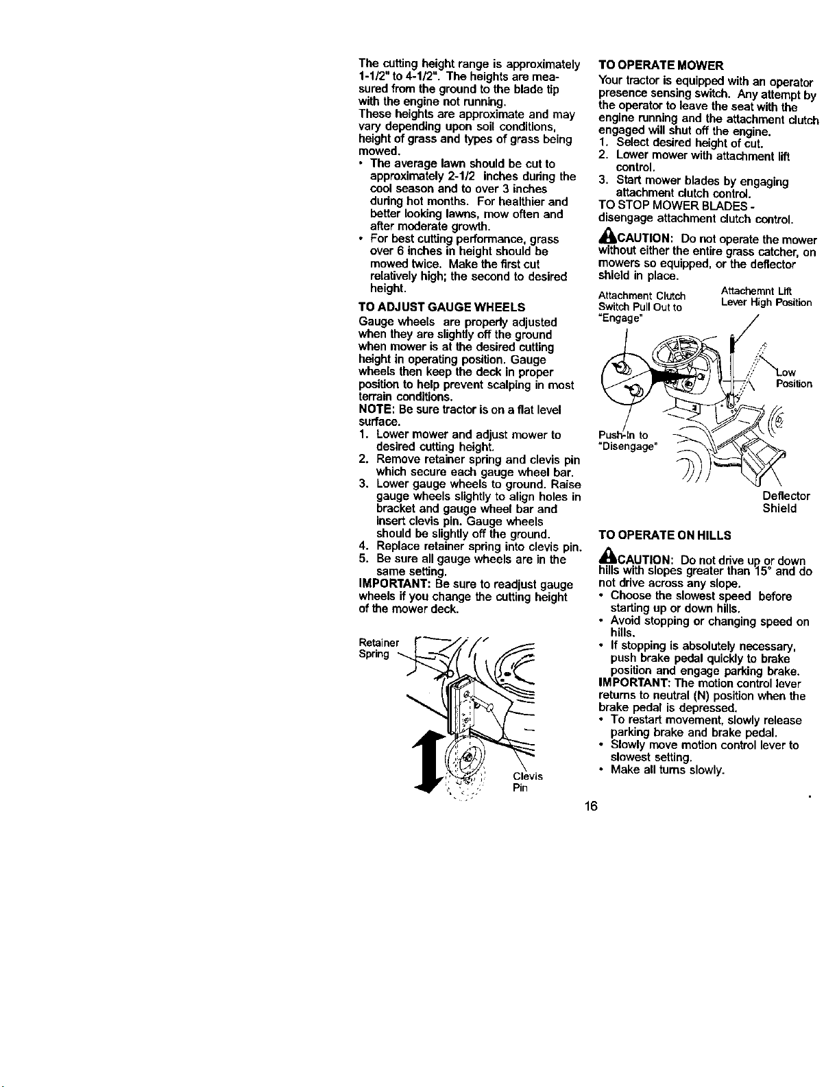
TO ADJUST GAUGE WHEELS
Gauge wheels are properly adjusted
when they are slightly off the ground
when mower is at the desired cutting
height in operating position. Gauge
wheels then keep the deck in proper
position to help prevent scalping in most
terrain conditions.
NOTE: Be sure tractoris on a flat level
surface.
1. Lower mower and adjust mower to
desired cutting height.
2. Remove retainer spdng and clevis pin
which secure each gauge wheel bar,
3. Lowergauge wheels to ground. Raise
gauge wheels slightly to align holes in
bracket and gauge wheel bar and
insert clevis pin. Gauge wheels
should be slightlyoff the ground,
4. Replace retainer spdng into clevis pin.
5. Be sure all gauge wheels are in the
same setting.
IMPORTANT: Be sure to readjust gauge
wheels if you change the cutting height
of the mower deck,
Retainer
Spring
Clevis
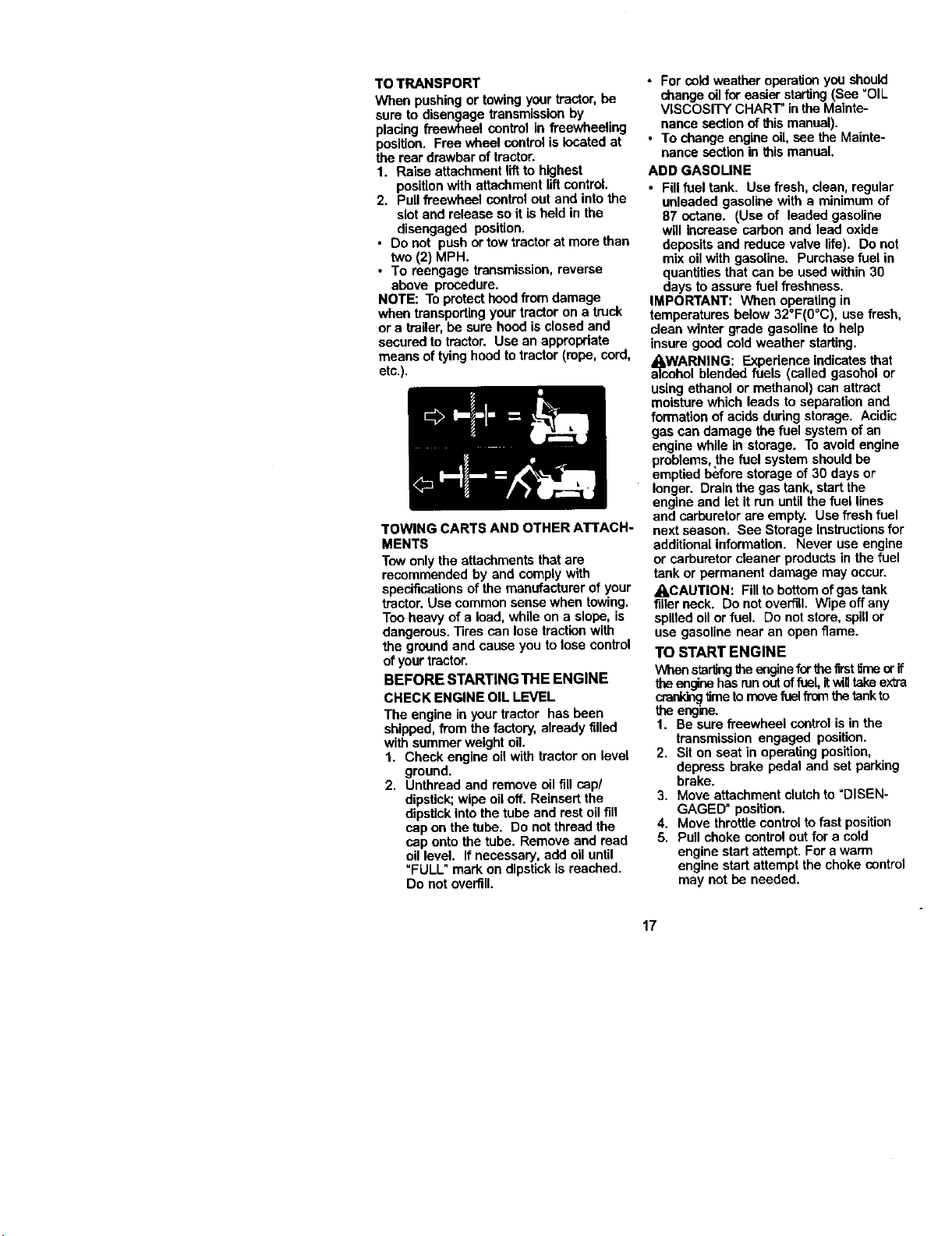
TO OPERATE MOWER
Your tractor is equipped with an operator
presence sensing switch. Any attempt by
the operator toleave the seat with the
engine running and the attachment clutch
engaged will shut off the engine.
1. Select desired height ofcut.
2. Lowermower with attachment lift
control.
3. Start mower blades by engaging
attachment clutchcontrel.
TO STOP MOWER BLADES -
disengage attachment clutch control.
,_CAUTION: Do notoperate the mower
withouteither the entire grass catcher, on
mowers so equipped, or the deflector
shield in place.
AttachmentClutch AttachemntLil_
SwitchPullOutto LeverHighPosition
"Engage"
Position
"Disengage"
Deflector
Shield
TO OPERATE ON HILLS
_'CAUTION: Do notddve up or down
hillswith slopes greater than 15° and do
notddve across any slope.
• Choose the slowest speed before
starting up or down hills.
• Avoid stoppingor changing speed on
hills.
• If stoppingis absolutely necessary,
push brake pedal quickly to brake
position and engage parking brake,
IMPORTANT: The motioncontrollever
returnsto neutral (N) positionwhen the
brake pedal is depressed.
• To restart movement, slowly release
parking brake and brake pedal.
• Slowly move motioncontrol lever to
slowest setting.
• Make all turns slowly.
16
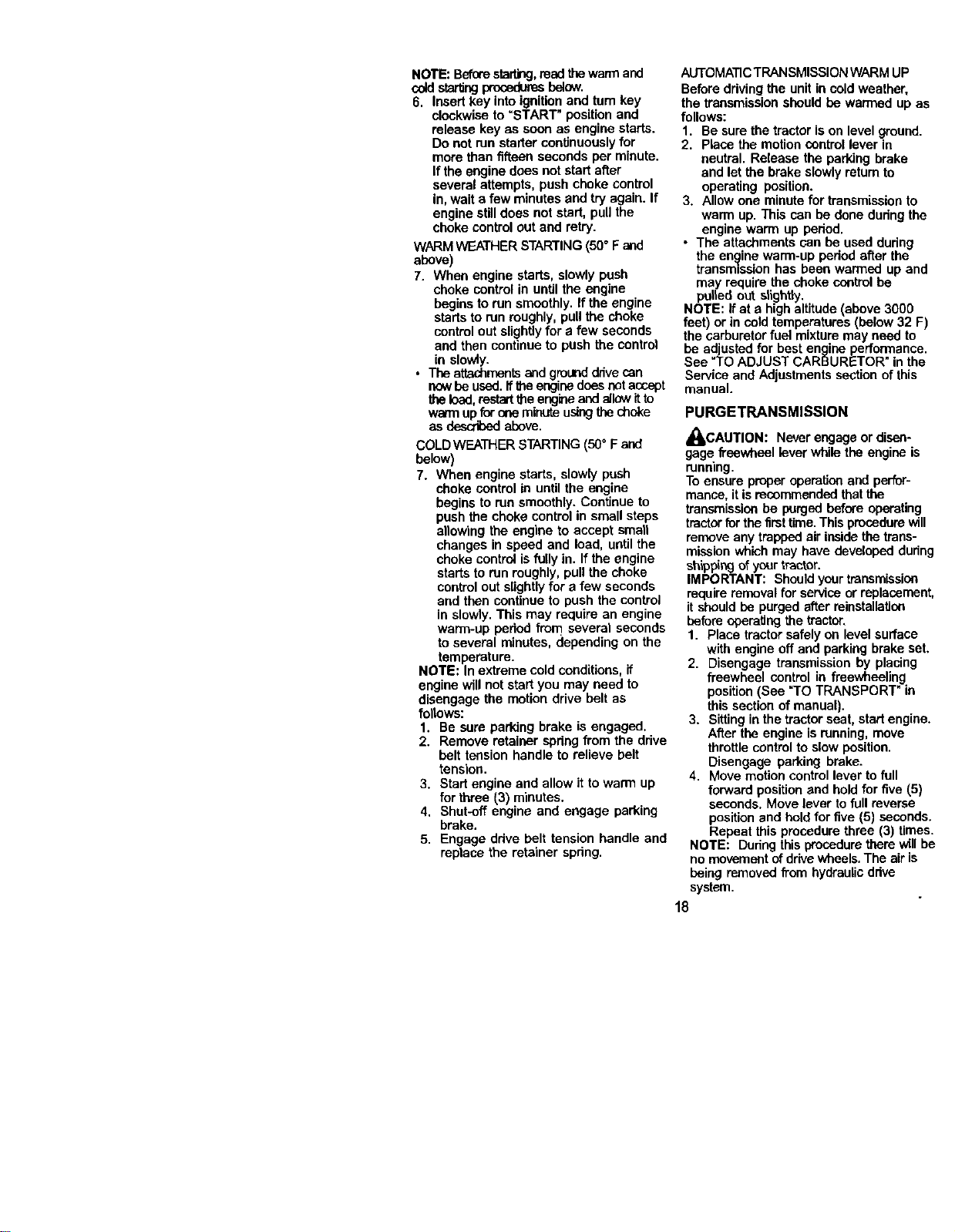
TO TRANSPORT
When pushing or towing yourtractor, be
sure to disengage transmission by
placing freewheel control in freewheeling
position. Free wheel control is located at
the rear drawbar oftractor.
1. Raise attachment liftto highest
position with attachment liftcontrol.
2. Pull freewheel control out and into the
slot and release so it is held in the
disengaged position.
• Do not push or towtractor at more than
two (2) MPH.
• To reengege transmission, reverse
above procedure.
NOTE: To protect hood fromdamage
when transportingyour tractor on a truck
or a trailer,be sure hood is closed and
securedto tractor. Use an appropriate
means of tying hoodto tractor (rope, cord,
etc.).
TOWING CARTS AND OTHER ATTACH-
MENTS
Tow only the attachments that are
recommended by and complywith
specificationsof the manufacturer of your
tractor.Use common sense when towing.
Too heavy of a load, while on a slope, is
dangerous. ]]ros can lose tractionwith
the ground and cause you to lose control
of yourtractor.
BEFORE STARTING THE ENGINE
CHECK ENGINE OIL LEVEL
The engine in your tractor has been
shipped, from the factory, already filled
with summer weight oil.
1. Check engine oil with tractoron level
ground.
2. Unthread and remove oil fill cap/
dipstick;wipe oiloff. Reinsert the
dipstick into the tube and rest oil fill
cap on the tube. Do not thread the
cap onto the tube. Remove and read
oil level. If necessary, add oil until
=FULL" mark on dipstick is roached.
Do not overfill.
• For cold weather operation you should
change oilfor easier starting (See =OIL
VISCOSITY CHART" in the Mainte-
nance sectionof this manual).
• To change engine oil,see the Mainte-
nance section in this manual.
ADD GASOLINE
• Fill fuel tank. Use fresh, clean, regular
unleaded gasoline with a minimum of
87 octane. (Use of leaded gasoline
will increase carbon and lead oxide
depositsand reduse valve life). Do not
mix oil with gasoline. Purchase fuel in
quantitiesthat can be used within 30
days to assure fuel freshness.
IMPORTANT: When operatingin
temperatures below 32°F(0°C), use fresh,
clean winter grade gasoline to help
insure good cold weather starting.
a_WhARNING: Experience indicatesthat
ol blended fuels (called gasohol or
using ethanol or methanol) can attract
moisture which leads to separation and
formation of acids dudng storage. Acidic
gas can damage the fuel systemof an
engine while in storage. To avoid engine
problems, the fuel system should he
emptied befere storage of 30 days or
longer. Drain the gas tank, start the
engine and let it run untilthe fuel lines
and carburetor are empty. Use fresh fuel
nextseason. See Storage Instructionsfor
additional information. Never use engine
or carburetor cleaner productsin the fuel
tank or permanent damage may occur.
_,CAUTION: Fillto bottom of gas tank
fillerneck. Do not overfill. Wipe off any
spilled oilor fuel. Do not store, spillor
use gasoline near an open flame.
TO START ENGINE
Whenstartingtheenginefor_e timtlime orif
theenginehasrunout offuel, itwintakeextra
crank_ time tomovefuelfromthetankto
the engine.
1. Be sure freewheel control is in the
transmission engaged position.
2, Sit on seat in operating position,
depress brake pedal and set parking
brake.
3. Move attachment clutchto "DISEN-
GAGED" position.
4. Move throttle control to fast position
5. Pull choke control out for a cold
engine start attempt. For a warm
engine start attempt the choke control
may not he needed.
17
NOTE: Beforestarting,readthewarmand
coldstarlingproceduresbelow.
6. Insert key into ignitionand tum key
clockwise to "START" positionand
release key as soon as engine starts.
Do not run stader continuouslyfor
more than fifteen seconds per minute.
If the engine does notstad after
several attempts, push choke control
in, wait a few minutes and try again. If
engine stilldoes not start, pull the
choke control out and retry.
WARMWEATHER STARTING(50° F and
above)
7. When engine starts, slowly push
choke control in until the engine
begins to run smoothly. If the engine
starts to run roughly, pull the choke
control out slightly for a few seconds
and then continue to push the control
in slowly.
• The attachmentsand grounddrive can
nowbe used.Ifthe enginedoesnotaccept
theload,restartthe engineand allowitto
warm upforone minute usingthechoke
as d_,cribed above.
COLDWEATHER STARTING (50° F and
below)
7. When engine starts, slowly push
choke control in untilthe engine
begins to run smoothly. Continue to
push the choke control in small steps
allowing the engine to accept smart
changes in speed and load, until the
choke contro_isfully in. If the engine
startsto run roughly, pull the choke
controlout slightlyfor a few seconds
and then continue to push the control
in slowly. This may require an engine
warm-up period from several seconds
to several minutes, depending on the
temperature.
NOTE: In extreme coldconditions,if
engine will notstartyou may need to
disengage the motion drive belt as
follows:
1. Be sure parking brake is engaged.
2. Remove retainer spring from the drive
belt tension handle to relieve belt
tension.
3. Start engine and allow it to warm up
for three (3) minutes.
4. Shut-off engine and engage parking
brake.
5. Engage drive belt tension handle and
replace the retainer spring.
AUTOMATICTRANSMISSION WARM UP
Before drivingthe unitin cold weather,
the transmissionshould be warmed up as
follows:
1. Be sure the tractor ison level ground.
2. Place the motioncontrol lever in
neutral. Release the parking brake
and let the brake slowly retum to
operating position.
3. Allow one minute for transmissionto
warm up. This can be done duringthe
engine warm up period.
• The attachments can be used during
the engine warm-up period after the
transmissionhas been warmed up and
may require the choke control he
pulled out slightly.
NOTE: Ifat a high altitude (above 3000
feet) or in coldtemperatures (below 32 F)
the carburetor fuel mixture may need to
be ad__ustedfor best engine performance.
See TO ADJUST CARBURETOR in the
Service and Adjustments section of this
manual.
PURGETRANSMISSION
_CAUTION: Never engage or disen-
gage freewheel lever while the engine is
running.
To ensure proper operationand perfor-
mance, itis recommendedthat the
transmissionbe purged before operating
tractorfor the firsttime.This procedurewill
removeany trapped sir insidethe trans-
mission which may have developed during
shipping ofyour tractor.
IMPORTANT: Should your trsnsmissise
require removal for service or replacement,
it should be purged after ralestallatiou
beforeoperatingthe tractor.
1. Place tractor safely on level surface
with engine off and parking brake set.
2. Disengage transmission by placing
freewheel control in freewheeling
position (See "TO TRANSPORT" in
this section of manual).
3. Sitting in the tractor seat, start engine.
After the engine isrunning, move
throttle control to slow position.
Disengage parking brake.
4. Move motion control lever to full
forward positionand hold for five (5)
seconds. Move lever to full reverse
position and hold for five (5) seconds.
Repeat this procedure three (3) times.
NOTE: During this procedurethere will be
no movement of drive wheels. The air is
being removed from hydraulic drive
system.
18
5. Move motion control lever to neutral
(N) position. Shut- off engine and set
parking brake.
6. Engage transmission by placing
freewheel ceetrol in driving position
(See "TO TRANSPORT" in this section
of manual).
7. Sittingin the tractor seat, start engine.
After the engine is running, move
throttlecontrol tohaft (1/2) speed.
Disengage parking brake.
8. Slowly move motioncontrol lever
forward, after the tractormoves
approximately five (5) feet, slowly
move motion control lever to reverse
position. After the tractormoves
approximately five (5) feet returnthe
motioncontrol lever to the neutral (N)
position. Repeat this procedure with
the motion control lever three (3)
times.
Your tractor is now purged and now ready
for normal operation.
MOWlNGTIPS
• Tire chains cannot be used when the
mower housing isattached to tractor,
• Mower should be propadyleveled for
best mowing performance. See "TO
LEVEL MOWER HOUSING" in the
Service and Adjustmentssection of this
manual.
• The left hand side of mower should be
used for trimming.
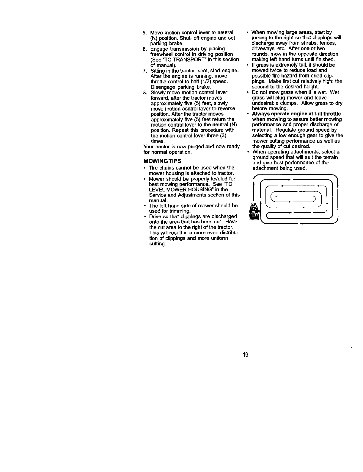
• Ddve so that clippings are discharged
onto the area that has been cut. Have
the cut area to the dght ofthe tractor.
This will result in a more even distribu-
tion of clippings and more uniform
cutting,
• 'Whenmowinglarge areas, start by
turningto the rightso that clippingswill
discharge away from shrubs, fences,
driveways, etc. After one or two
rounds, mow in the opposite direction
making left hand turns untilfinished.
• If grass is extremely tall, it should be
mowed twice to reduce load and
possiblefire hazard from dded clip-
pings. Make firstcut relativelyhigh;the
second to the desired height.
• Do not mow grass when itis wet. Wet
grass will plug mower and leave
undesirable clumps. Allow grass to dry
before mowing.
• Always operate engine at full throttle
when mowing toassure better mowing
performance and proper discharge of
matedal. Regulate ground speed by
selecting a low enough gear to give the
mower cuttingperformance as well as
the qualityof cut desired.
• When operatingattachments, select a
ground speed that will suit the terrain
and give best performance ofthe
attachment being used.
J
19
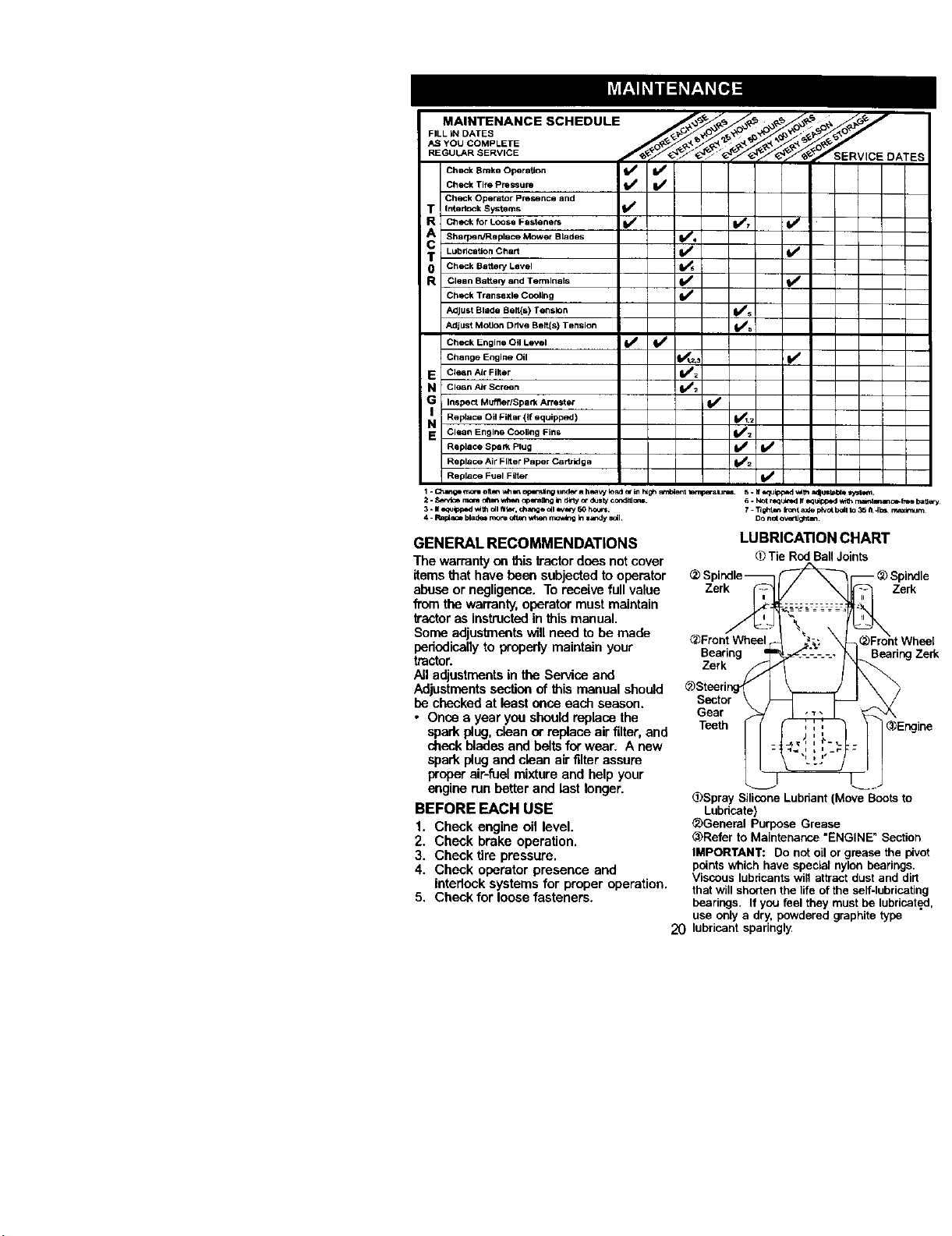
AS YOU COMPLETE
.EOU .s .v.o o*T a
CheckBrake Operation _ If
Check Tire Pressure fl_ I_/
Check Operator presence and
T !l r_dockSystems I1_
R Check for LOOSe Fasteners I1_ 1_7 If
CA SharpelVReplece Mower Blades I_,
T Lubrtcation Chart V t V w
0 CheCk BetteP/Level
R clean Battery and Tenmlnals ll_ (1_
Check Tranaaxle Cooling
Adjust Blade Belt(s) Tension [l_s
Adjust Motion Drive Belt(s) Tension _5
Check Engine Oil Level I_ ll_
Change Engine Oil I_t 2._ I_
E CleanAirFilter If=
a Clean A_rScreen I_=
G Inspect Muffler/Spark Arrester I_
Replace Oil Filter (If equipped) I_1.=
N Clean Engine CCollng Fins I_=
Replace Spall_ Plug [1_ I_
Replace Air Filter Paper Cartridge 1_2
ReplaCe Fuel Filter I_
1- Change r;"_rwoft m_v_ an opersJng undo" a h_'_ load _" Lnhd_ _t _a_ 5. ff _ilpped v_lh _Ul s,_t_.
2 - Sir, ice rr_ _n v.@_t _n;_g In _ly _" dusW cond_J _r4. 6. Not rJq_h_d ffe.quipped _ mam_ce.;_e_ battery
3 - If_q_tpped v.lth cq _. chang_ C_l_e_3' 60 hOUr. 7. "rlght_ Ir_t _ I_VOt b_l to 35 h 4_ rn_m_ m
4 - Rar_ blad_ nxxo _t_ v.t_m rr_v_O kl =andy soil DO n_ ov_lJght_.
GENERAL RECOMMENDATIONS
The warranty on thistractordons not cover
itemsthat have been subjectedto operator
abuse or negligence. To receivefull value
from the warranty,operator must maintain
tractor as instructedin this manual.
Soma adjustmentswill need tobe made
periodically to properly maintain your
tractor.
All adjustmentsin the Service and
Adjustmentssectionof this manual should
be checked at least once each season.
• Once a year yea should replace the
spark plug,clean or replace air filter, and
check blades and beltsforwear. A new
spark plug andclean air filter assure
proper air-fuelmixture and help your
engine run better and last longer.
BEFORE EACH USE
1. Check engine oil level.
2. Check brake operation.
3. Check tire pressure.
4. Check operator presence and
interlocksystems for proper operation.
5. Check for loose fasteners.
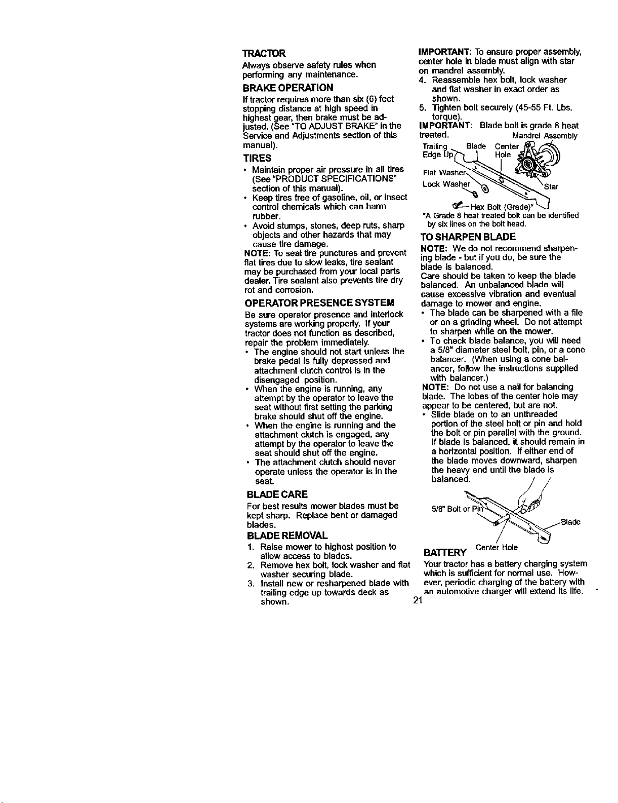
LUBRICATION CHART
(T)Tie RodBallJoints
Zerk Zerk
_Fmnl
Bearing
Zerk
Gear
Teeth
Bearing Zerk
(]._SpraySilicone Lubdant (Move Boots to
Lubricate)
_General Purpose Grease
@Refer to Maintenance "ENGINE" Section
IMPORTANT: Do not oil or grease the pivot
pointswhich have special nylon bearings.
Viscous lubricants wifl attract dust and dirt
that will shorten the life ofthe self-lubricating
bearings. If you feel they must be lubricated,
use only a dry, powdered graphite type
20 lubricant sparingly
TRACTOR
Always observe safety rules when
performing any maintenance.
BRAKE OPERATION
Iftractor requires more than six (6) feet
stopping distance at high speed in
highestgear, then brake must be ad-
justed. (See =TOADJUST BRAKE" in the
Service and Adjustments section ofthis
manual).
TIRES
• Maintain proper air pressure in all tires
(See "PRODUCT SPECIFICATIONS"
section of this manual).
• Keep tires free of gasoline, oil, or insect
control chemicals which can harm
rubber.
• Avoid stumps, stones, deep ruts, sharp
objects and other hazards that may
cause tire damage.
NOTE: To seal tire punctures and prevent
fiat tires due to slow leeks, tire sealant
may be purchased from your local parts
dealer. Tire sealant also prevents tire dry
rot and corrosion.
OPERATOR PRESENCE SYSTEM
Be sure operator presence and interlock
systems are working properly. If your
tractor does not function as described,
repair the problem immediately.
• The engine should not start unless the
brake pedal is fully depressed and
attachment clutchcontrol isin the
disengaged position.
• When the engine is running, any
attempt by the operator to leave the
seat without first setting the parking
brake should shut off the engine.
• When the engine is running and the
attachment clutch is engaged, any
attempt by the operator to leave the
seat should shut off the engine.
• The attachment clutch should never
operate unless the operator is in the
seat.
BLADE CARE
For best results mower blades must be
keptsharp. Replace bent or damaged
blades.
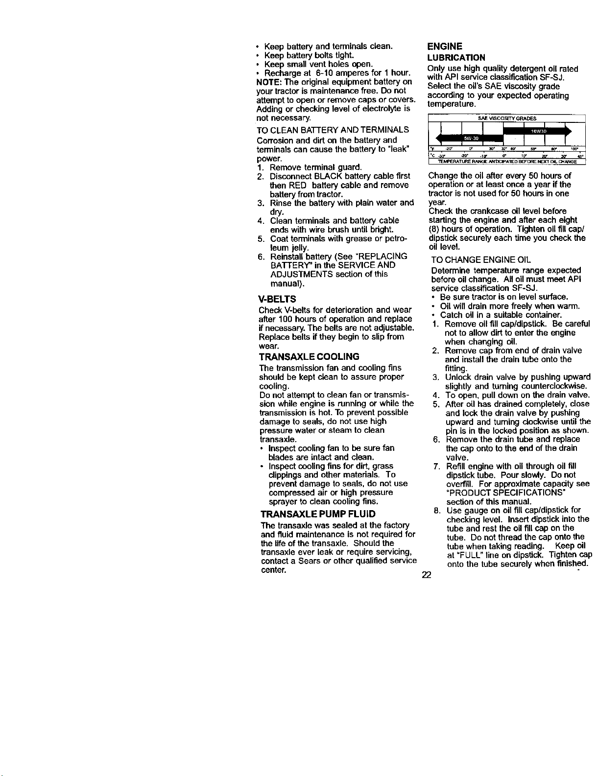
BLADE REMOVAL
1. Raise mower to highest positionto
allow access to blades.
2. Remove hex bolt, lock washer and fiat
washer securing blade.
3. install new or resharpened blade with
trailingedge up towards deck as
shown.
IMPORTANT: To ensure proper assembly,
center hole in blade must alignwith star
on mandrel assembly.
4. Reassemble hex bolt, lock washer
and fiat washer in exact order as
shown.
5. Tighten boltsecurely (45-55 Ft. Lbs.
torque).
IMPORTANT: Blade boltis grade 8 heat
treated. Mandrel Assembly
Trailin Blade Center
EdgeUI: Hole
_-_ HexBolt
*A Grade8 heattreatedbolt can beidentified
bysixlinesont_e bolt head.
TO SHARPEN BLADE
NOTE: We do not recommend sharpen-
ing blade - but ifyou do, be sure the
blade is balanced.
Care should be taken to keep the blade
balanced. An unbalanced blade will
cause excessive vibrationand eventual
damage to mower and engine.
• The blade can be sharpened with a file
or on a gdndingwheel. Do notattempt
to sharpen while on the mower.
• To check blade balance, you will need
a 5/8" diameter steel bolt, pin, or a cone
balancer. (When using a cone hal-
ancar, follow the instructionssupplied
with belancer.)
NOTE: De net use a nailfor balancing
blade. The lobes of the center hole may
appear to be centered, but are not,
• Slide blade on to an unthreaded
portionof the steel boltor pin and hold
the boltor pin parallel with the ground.
If blade is balanced, it should remain in
a hodzontal position. If either end of
the blade moves downward, sharpen
the heavy end untilthe blade is
Blade
Center Hole
BA'I-rERY
Your tractor has a battery chargingsystem
which is sufficientfor normal use. How-
ever, periodic charging of the battery with
an automotive charger will extend its life.
21
• Keep battery and terminals clean.
• Keep battery bolts tight.
• Keep small vent holes open.
• Recharge at 6-10 amperes for 1 hour.
NOTE: The original equipment battery on
your tractor ismaintenance free. Do not
attempt to open or remove caps or covers.
Adding or checking level of electrolyte is
notnecessary.
TO CLEAN BATTERY AND TERMINALS
Corrosion and dirt on the battery and
terminalscan cause the battery to "leak"
power.
1. Remove terminal guard.
2. Disconnect BLACK battery cable first
then RED battery cable and remove
batteryfrom tractor.
3. Rinse the battery with plain water and
dry.
4. Clean terminals and battery cable
ends with wire brush until bright.
5. Coat terminals with grease or petro-
leum jelly.
6. Reinstall battery (See "REPLACING
BATTERY" in the SERVICE AND
ADJUSTMENTS section of this
manual).
V-BELTS
Check V-belts for deterioration and wear
after 100 hours of operation and replace
if necessary.The bolts are not adjustable.
Replace belts if they begin to slipfrom
wear.
TRANSAXLE COOLING
The transmission fan and coolingfins
should be kept clean to assure proper
cooling.
Do not attempt toclean fan or transmis-
sion while engine is running or while the
transmission is hot. To prevent possible
damage to seals, do not use high
pressure water or steam to clean
transaxle.
• Inspect coolingfan to be sure fan
blades are intact and clean.
• Inspect coolingfinsfor dirt, grass
clippingsand other materials. To
prevent damage to seals, do not use
compressed air or high pressure
sprayer to clean cooling fins.
TRANSAXLE PUMP FLUID
The transaxle was sealed at the factory
and fluid maintenance is not required for
the life ofthe transaxle. Should the
transaxle ever leak or require servicing,
contact a Sears or other qualified service
center.
ENGINE
LUBRICATION
Only use high quality detergent oil rated
withAPI service classificationSF-SJ.
Select the oil's SAE viscosity grade
according to your expected operating
temperature.
Change the oil after every 50 hours of
operationor at least once a year if the
tractor is not usedfor 50 hours in one
year.
Check the crankcase oil level before
starting the engine and after each eight
(8) hours ofoperation. Tighten oilfill cap/
dipstick securely each time you check the
oil level.
TO CHANGE ENGINE OIL
Determine temperature range expected
before oil change. All oil must meet API
service classification SF-SJ.
• Be sure tractor is on level surface.
• Oil will drain more freely when warm.
• Catch oil in a suitable container.
1. Remove oil fill cap/dipstick. Be careful
not to allow dirt to enter the engine
when changing oil.
2. Remove cap from end of drain valve
and install the drain tube onto the
fitting.
3. Unlock drain valve by pushing upward
slightly and turning counterclockwise.
4. To open, pull down on the drain valve.
5. After oil has drained completely, close
and lock the drain valve by pushing
upward and turning clockwise untilthe
pin is in the locked position as shown.
6. Remove the drain tube and replace
the cap onto to the end of the drain
valve.
7. Refill engine with oil through oil fill
dipstick tube. Pour slowly. Do not
overfill. For approximate capacity see
"PRODUCT SPECIFICATIONS"
section of this manual.
8. Use gauge on oil fill cap/dipstlek for
checking level. Insert dipstick into the
tube and rest the oil fill cap on the
tube. Do not thread the cap onto the
tube when taking reading. Keep oil
at "FULL" line on dipstick. Tighten cap
onto the tube securely when finished.
22
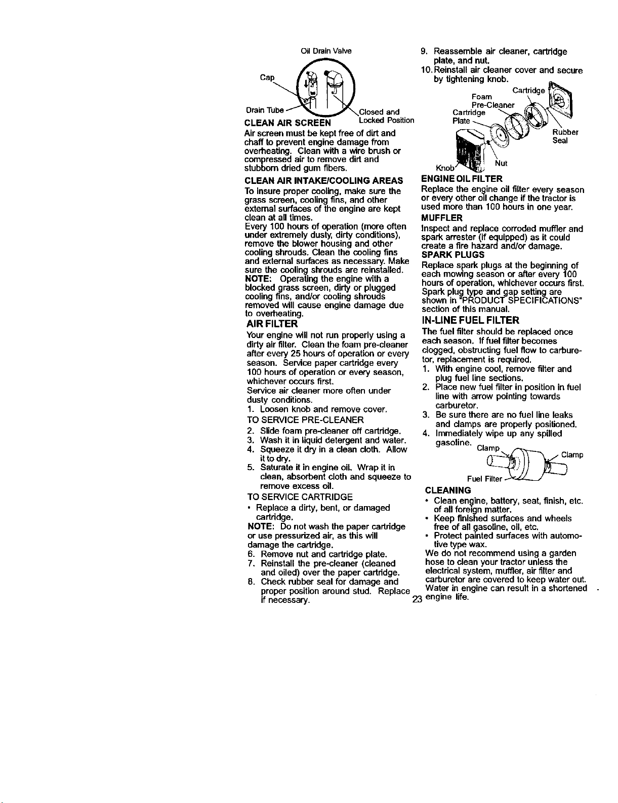
OilDrainValve
Draii_ube_closed and
CLEAN AIR SCREEN LockedPosition
Air screen must be keptfree of dirt and
chaff to prevent engine damage from
overheating. Clean with a wire brush or
compressed air to remove dirt and
stubbom dried gum fibers.
CLEAN AIR INTAKEICOOLING AREAS
To insure proper cooling, make sure the
grass screen, cooling fins, and other
external surfaces of the engine are kept
clean at all times.
Every 100 hours of operation (mare often
under extremely dusty, dirty conditions),
remove the blower housing and other
cooling shrouds. Clean the cooling fins
and external surfaces as necessary. Make
sure the cooling shrouds are reinstalled.
NOTE: Operating the engine with a
blocked grass screen, dirty or plugged
coolingfins, and/or cooling shrouds
removed will cause engine damage due
to overheating.
AIR FILTER
Your engine will not run properly using a
dirty air filter. Clean the foam pre-cleaner
after every 25 hours of operation or every
season. Service paper cartridge every
100 hours of operation or every season,
whichever occurs first.
Service air cleaner more often under
dusty conditions.
1. Loosen knob and remove cover.
TO SERVICE PRE-CLEANER
2. Slide foam pre-cleaner off cartridge.
3. Wash it in liquid detergent and water.
4. Squeeze it dry in a clean cloth. Allow
itto dry.
5. Saturate it in engine oil. Wrap it in
clean, absorbent cloth and squeeze to
remove excess oil.
TO SERVICE CARTRIDGE
• Replace a dirty,bent, or damaged
cartridge.
NOTE: Do not wash the paper cartridge
or use pressurized air, as this will
damage the cartridge.
6. Remove nut and cartridge plate.
7. Reinstall the pre-cleaner (cleaned
and oiled) over the paper cartridge.
8. Check rubberseal for damage and
proper position around stud. Replace
if necessary.
9. Reassemble air cleaner, cartridge
plate, and nut.
10. Reinstall air cleaner cover and secure
by tighteningknob.
Cartridge
Foam
Pre-Cleaner
Cartridge
Rubber
Seal
Nut
Knob
ENGINE OIL FILTER
Replace the engine oil filter every season
or every other oilchange if the tractor is
used more than 100 hours in one year.
MUFFLER
Inspect and replace corroded muffler and
spark arrester (ifequipped) as it could
create a fire hazard and/or damage.
SPARK PLUGS
Replace spark plugs at the beginning of
each mowing season or after every 100
hours ofoperation, whichever occurs first.
Spark plug type and gap setting are
shown in "PRODUCT SPECIFICATIONS"
section of this manual.
IN-LINE FUEL FILTER
The fuel filtershould be replaced once
each season. Iffuel filter becomes
clogged, obstructingfuel flow to carbure-
tor, replacement is required.
1. With engine cool, remove filter and
plug fuel line sections,
2. Place new fuel filter in position in fuel
line with arrow pointingtowards
carburetor.
3. Be sure there are no fuel line leaks
and damps are properly positioned.
4. Immediately wipe up any spilled
gasoline. Cl_Lam p
FuelFilter
CLEANING
• Clean engine, battery, seat, finish,etc.
of all foreign matter.
Keep finished surfaces and wheels
i free of all etc,
gasoline,
ell,
Protect painted surfaces with automo-
tive type wax.
We do not recommend using a garden
hose to clean your tractor unless the
electrical system, muffler, air filterand
carburetor are covered to keep water out.
Water in engine can result in a shortened .
23 engine life.
_CAUTIONt BEFORE PERFORMING ANY SERVICE ORADJUSTMENTS:
1. Depress brake pedal fully and set parking brake.
2. Place attachment clutch in °DISENGAGED" position.
3. Turn ignitionkey "OFF" and remove key.
4, Make sure the blades and all moving parts have completely stopped.
5. Disconnect spark plug wire from spark plug and place wire where it cann(
come in contactwith plug,
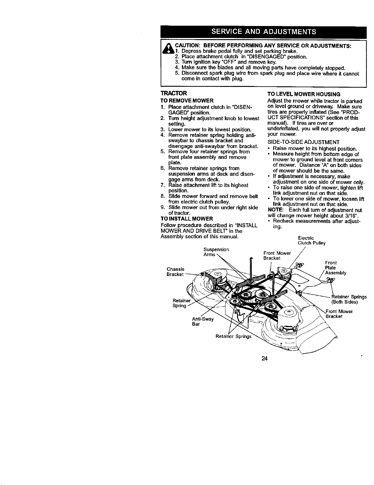
TRACTOR
TO REMOVE MOWER
1. Place attachment clutchin "DISEN-
GAGED" position.
2. Turn height adjustment knob to lowest
setting.
3. Lower mower to its lowest position.
4. Remove retainer spdng holding anti°
swaybar to chassis bracket and
disengage anti-swayber from bracket.
5. Remove four retainer springsfrom
front plate assembly and remove
plate.
6, Remove retainer springs from
suspension arms at deck and disen-
gage arms from deck.
7. Raise attachment liftto its highest
position.
8. Slide mower forward and remove belt
from elect_c clutch pulley.
9. Slide mower out fTomunder dght side
oftractor.
TO INSTALL MOWER
Follow procedure described in "INSTALL
MOWER AND DRIVE BELT"in the
Assembly section of this manual.
Suspension
Chassis
TO LEVEL MOWER HOUSING
Adjust the mower while tractor is park
on level ground or driveway. Make st
tires are propedy inflated (See =PRO[
UCT SPECIFICATIONS" sectionofthi
manual). If tires are over or
undednflated, you will not propedy a(
your mower.
SIDE-TO-SIDE ADJUSTMENT
• Raise mower to its highest position
• Measure height from bottomedge
mower to ground level at front corn
of mower. Distance "A"on both sic
of mower should be the same.
• If adjustmentis necessary, make
adjustment on one side of mower {
• To raise one side of mower, tighter
linkadjustment nut on that side.
• To lower one side of mower, loose
linkadjustment nut on that side.
NOTE: Each full tam of adjustment r
will change mower height about 3/16'
• Recheck measurements after adju,_
ing,
Electric
Clutch Pulley
Front Mower
Bracket
Front
Plate
Retainer
Sprin!
Anti-Sway
Bar
Retainer St_
(Both Side_
Bracket
24
BottomEdgeof BottomEdgeof
Mowerto Ground Mowerto Ground
\ /
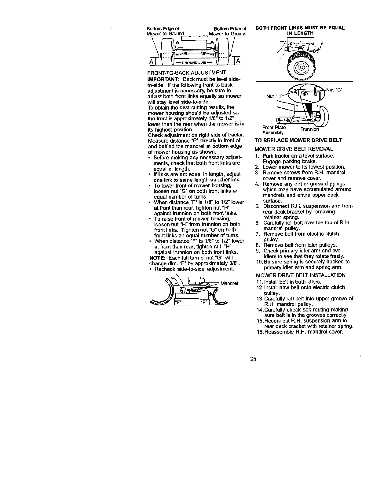
FRONT-TO-BACK ADJUSTMENT
IMPORTANT: Deck must be level side-
to-side. If the following front-to-back
adjustment is necessary, be sure to
adjust both front links equally so mower
will stay level side-to-side.
To obtain the bestcutting results,the
mower housing should be adjusted so
the front isapproximately 1/8" to 1/2"
lower than the rear when the mower is in
its highest position.
Check adjustment on right side of tractor.
Measure distance "F"directlyin front of
and behind the mandrel at bottom edge
of mower housing as shown.
• Before making any necessary adjust-
ments, check that both front links are
equal in length.
• If links are notequal in length, adjust
one link to same length as other link.
• To lower front of mower housing,
loosen nut"G"on both front linksan
equal number of turns.
• When distance "F"is 1/8" to 1/2" lower
at front than rear, tighten nut "H"
against trunnionon both front links.
• To raise front of mower housing,
loosen nut "H"from trunnionon both
front links. Tighten nut "G"on both
front links an equal number of turns.
• When distance "F"is 1/8" to 1/2" lower
at frontthan rear, tightennut "H"
against trunnionon both front links.
NOTE: Each full rum ofnut =G" will
change dim. "F" by approximately 3/8".
• Recheck side-to-side adjustment.
Mandrel
BOTH FRONT LINKS MUSTBE EQUAL
IN LENGTH
Front Plate Trunnion
Assembly
TO REPLACE MOWER DRIVE BELT
MOWER DRIVE BELT REMOVAL
1. Park tractor ona level surface.
Engage parking brake.
2. Lower mower to its lowest position.
3. Remove screws from R.H. mandrel
cover and remove cover.
4. Remove any dirtor grass clippings
which may have accumulated around
mandrels and entire upper deck
surface.
5. Disconnect R.H. suspensionarm from
rear deck bracket by removing
retainer spdng.
6. Carefully roll belt over the top of R.H.
mandrel pulley.
7. Remove belt from electdc clutch
pulley.
8. Remove belt from idler pulleys.
9. Check primary idler arm and two
idlersto see that they rotate freely.
10. Be sure spdng is securely hooked to
pdmary idler arm and spdng arm.
MOWER DRIVE BELT INSTALLATION
11. Install belt in both idlers.
12.Install new belt onto electric clutch
pulley.
13.Carefully roll belt into upper grooveof
R.H. mandrel pulley.
14.Carefully check belt routingmaking
sure belt is in the grooves correctly.
15. Reconnect R.H. suspension arm to
rear deck bracket with retainer spdng.
16.Reassomble R.H. mandrel cover,
25

ElectrLc
Idler
Spring
R.H,
Primary
TO REPLACE MOWER BLADE DRIVE
BELT
Park the tractoron level surface. Engage
parking brake.
1. Remove mower ddve belt (See "TO
REPLACE MOWER DRIVE BELT"in
this section of this manual).
2. Remove mower (See "TO REMOVE
MOWER" In this section ofthis
manual).
3. Remove screws from L.H. mandrel
cover and remove cover.
4. Carefully roll belt off L.H. mandrel
pulley.
5. Remove belt from center mandrel
pulley, idler pulley, and R.H. mandrel
pulley.
6. Remove any dirt or grass which may
have accumulated around mandrels
and entire upper deck surface.
7. Check secondary idler arm and idler
pulleyto see that they rotate freely.
8. Be sure spdng is hooked in secondary
idler ann and secondary spring arm.
9. Install new belt in lower groove of R.H.
mandrel pulley, idler pulley, and
center mandrel pulley as shown.
10.Carefully roll belt over L.H. mandrel
pulley. Make sure belt is in all
grooves properly.
11.Reinstall L.H. mandrel cover.
12.Reinstall mower to tractor (See
"INSTALL MOWER AND DRIVE
BELT" in the Assembly section of this
manual).
13. Reassemble mower drive belt (See
=TO REPLACE MOWER DRIVE BELT"
in this section of this manual).
Secondary Idler
LH. Idler Arm
Mandrel Pulley Spring
Secondary
Center
Mandrel
R.H.
Mandrel
TO ADJUST ATTACHMENT CLUTCH
The electric dutch should provideyears
of service. The clutchhas a built-inbrake
that stops the pulleywithin 5 seconds.
Eventually, the internal brake will wear
which may cause the mower blades to
notengage, or, to not stopas required.
Adjustments should be made by a Sears
or other qualified service center.
1. Make sure attachment clutch and
ignitionswitches are in "OFF" position.
2. Adjust the three nylonIocknutsuntil
space between clutch plate and rotor
measures .012" at all three slot
locationscut in the side of brake plate.
26

NOTE: After installinga new electric
clutch,run tractorat full throttleand
engage and disengage electdc clutch 10
cycles towear in clutch plate.
Rotor--_' ' ClutchPlate_...._. [012"
Slot(3)_ /! _ Brake
._>_F--_::_ , Plate
NylonLocknut(3)/
TO REPLACE MOTION DRIVE BELT
Park the tractor on level surface. Engage
parkingbrake. For ease of service there
is a belt installation guide decal on
bottomof leftfootrest.
1. Remove mower (See =TO REMOVE
MOWER" in this section of this
manual.)
BELTREMOVAL -
2. Create slack in belt by removing
retainer spdngfrom ddve belt tension
handle.
3. Remove belt from all idler pulleys,
trensaxle pulley and then from engine
pulley.
Retainer
Spring
DriveBelt""
Tension
Handle
e Pulley Transaxle Pulley
Belt Keeper
Clutching
Keeper V-Idler Clutching Flatldler
Idler
BELT INSTALLATION -
1. Install new belt around engine pulley
first, then around transaxle pulley and
lastly into all the idler pulleys.
2. Check to be sure belt is positioned
correctly and is on proper side of all
belt keepers.
3. Engage the ddve belt tension handle
and replace the retainer spring.
4. Reinstall mower.
TRANSAXLE MOTION CONTROL
LEVER NEUTRAL ADJUSTMENT
The motion control lever has been preset
at the factory and adjustment should not
be necessary.
1, Park Tractor on level surface, Stop
tractor byturningignitionkey to"OFF"
position and engage parking brake.
2. Loosen the adjustment bolt in front of
the right rear wheel,
3, Move motioncontrol lever to the
neutral position,
4, Tighten the adjustment bolt,
_ AdjustmentBolt
TRANSMISSION REMOVAL/REPLACE-
MENT
Should your transmission require
removal for service or replacement, it
should be purged after reinstallationand
before operating the tractor. See
"PURGE TRANSMISSION" in the
Operation section of this manual.
TO ADJUST STEERING WHEEL ALIGN-
MENT
If steering wheel crossbars are not
horizontal (left to right)when wheels are
positionedstraightforward, remove
steering wheel and reassemble per
instructionsin the Assembly section of
this manual.
FRONT WHEEL TOE-IN ADJUSTMENT
Frontwheel toe-in is required for proper
steering operation. Toe-inwas set at the
factory and adjustment should not be
necessary. If parts in the front axle or
steedng mechanism have been replaced
or damaged, check toe-in and adjust if
necessary.
TO CHECK TOE-IN -
1, Positionfront wheels straight ahead.
2. Measure distance between wheels at
front and rear of tires (dimensions =A"
and "B").
• Front dimension "A" should be 1/8" to
1/4" less than rear dimension =B".
TO ADJUST TOE-IN -
1. Loosen jam nuts at adjustment
sleeves on tie rod.
2. Adjust tie red until dimension °A" is
1/8" to 1/4" lessthan dimension=B".
3. Tighten jam nuts securely.
27
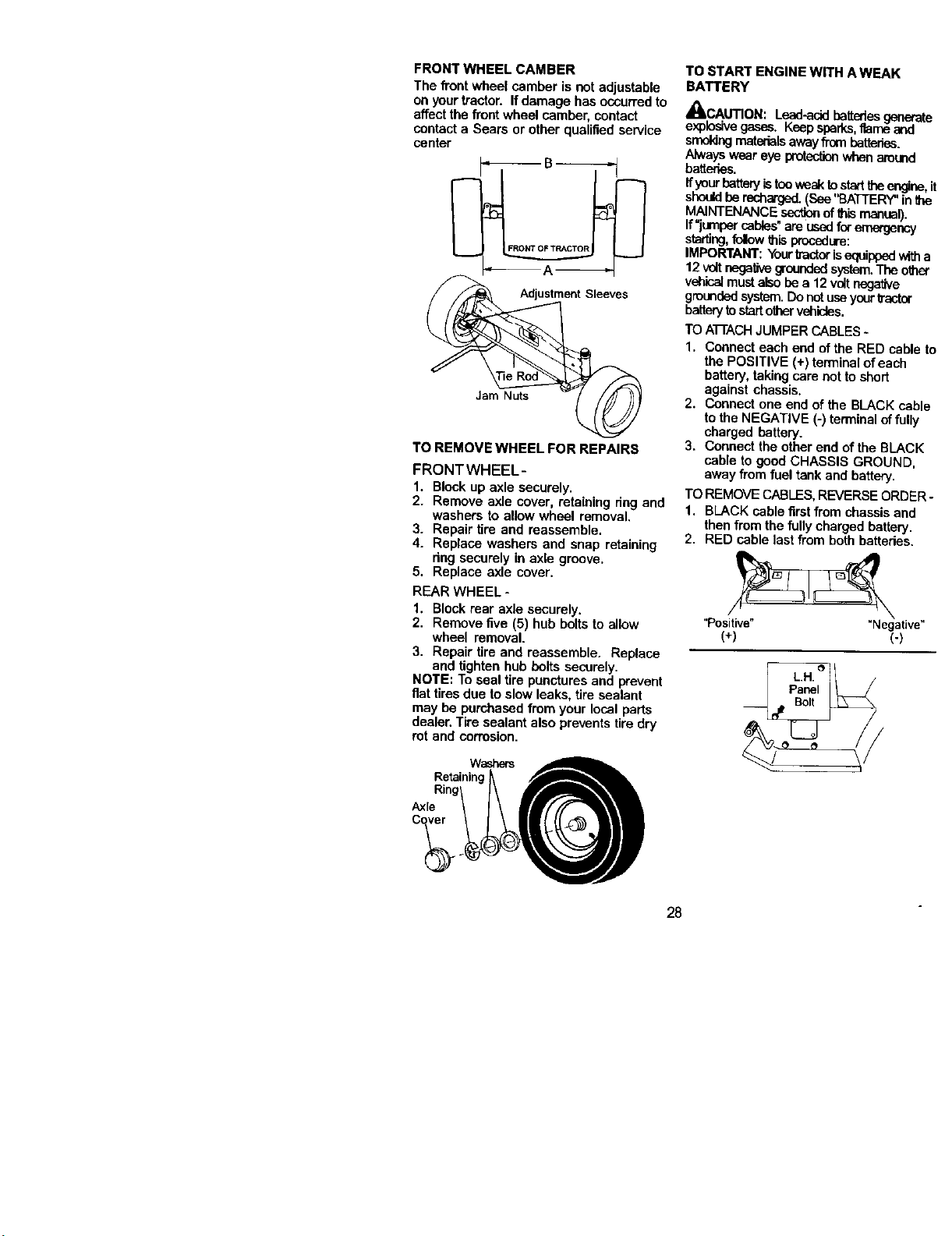
FRONTWHEELCAMBER
The front wbeel camber is not adjustable
onyour tractor. If damage has occurred to
affect the front wheel camber, contact
contact a Sears or other qualified service
center
Jam Nuts
TO REMOVE WHEEL FOR REPAIRS
FRONTWHEEL-
1. Block up axle securely.
2. Remove axle cover, retaining ring and
washers to allow wheel removal.
3. Repair tire and reassemble.
4. Replace washers and snap retaining
ring securely in axle groove.
5. Replace axle cover.
REAR WHEEL -
1. Block rear axle securely,
2. Remove five (5) hub bolts to allow
wheel removal.
3. Repair tire and reassemble. Replace
and tighten hub belts securely.
NOTE: To seal tire punctures and prevent
fiat tiresdue toslow leaks, tire sealant
may be purchased from your local parts
dealer. Tire sealant also prevents tire dry
rot and corrosion.
TO START ENGINE WITH A WEAK
BATTERY
_CAUTION: L.epd-acidbatteriesgen
explosivegases, i,_eepsparks,flame ar
srnoldngmaterialsawayfrom batteries.
Always wear eye protec_onwhen aro_
batteries,
Ifyourbetteryistooweaktostartg'leor_
shouldberechan:jed.(See "BATTERY"i
MAINTENANCE sectionof _ mam.taL/.
If=jumpercables"are usedforemergerK
starting,folow thisprocedure:
IMPORTANT: Yourtractorisequippedw
12volt negativegroundedsystem,The c
vehicalmustalsobe a 12voltnegative
groundedsystem.Donot useyour'6_actc
batterytostartothervehicles.
TO A'I-I'ACHJUMPER CABLES-
1. Connect each end of the RED cal
the POSITIVE (+) terminal ofeaci_
battery,takieg care not to short
against chassis,
2. Connect one end of the BLACK c
tothe NEGATIVE (-) terrnleaLoffL
charged battery.
3. Connect the other end of the BLA
cable to good CHASSIS GROUN _
away from fuel tank and battery.
TO REMOVE CABLES,REVERSE OR[
1. BLACK cable first from chassisal
then fromthe fully charged batter
2. RED cable lastfrom both betterie_
"Positive" "Negat_
(*) (-)
28

REPLACING BATFERY
_CAUTION: Do not short battery
terminalsby aUowing a wrench or any
other objectto contact both terminals at
the same time. Before connectingbattery,
remove metal bracelets, wristwatch
bands, dngs, etc.
Positiveterminal must be connected first
to prevent sparking from accidental
grounding.
1. Lift hoed to raised position.
2. Remove terminal guard.
3. Disconnect BLACK battery cable then
RED battery cable and carefully
remove batteryfrom tractor.
4. Install new batterywith terminals in
same position as old battery.
5. Reinstall terminal guard.
6. First connect RED battery cable to
positive (+) battery terminal with hex
bolt and keps nut as shown. Tighten
securely.
7. Connect BLACK groundingcable to
negative (-) battery terminal with
remaining hex holt and keps nut.
Tighten securely
8. Close terminal access doors.
9. Close hood.
Terminal Keps Nut Hex Bolt
Accesi_
Door
Positive
Terminal (Red)
Guard Cable
(Black)
,1__ Cable
TO REPLACE HEADLIGHT BULB
1. Raise hood.
2. Pull bulb holder out of the hole in the
backside of the grill
3. Replace bulb in holder and push bulb
holder securely back into the hole in
the backside of the gdll.
4. Close hoed.
INTERLOCKS AND RELAYS
Looseor damaged wiring may cause your
b'actortorun pnody,stopnJnning,or
preventitfrom starting.
• Check widng. See electdcal wiring
diagram in the Repair Parts section.
TO REPLACE FUSE
Replace with 30 amp automotive-type
plug-infuse. The fuse holder islocated
behind the dash.
TO ADJUST ATTACHMENT LIFT
SPRING
1. While holding spdng bushing with
wrench, loosen jam nut.
• Turn adjustment boltctockwise to
extend spdng and reduce lif_effortfor
heavier attachments.
• Turn adjustment holt counterclockwise
for lighter attachments.
2. Retighten jam nut against spdng
bushing.
IMPORTANT: Do not adjust for maxi-
mum spdng tensionwhen using light
attachments such as a mower. Adjustlift
lever spdng to aid in liftingattachment.
Do not overpower spdng. When remov-
ing attachment, always adjust spdng
tension toits lowest position.
ustment Bolt
Bushing
TO REMOVE HOOD AND GRILL
ASSEMBLY
1. Raise hood.
2. Unsnap headlight wire connector.
3. Stand infront of tractor. Grasp hood
at sides, tilttoward engine and liftoff
oftractor.
4. To replace, reverse above procedure.
Headlight Wire
Connector
29
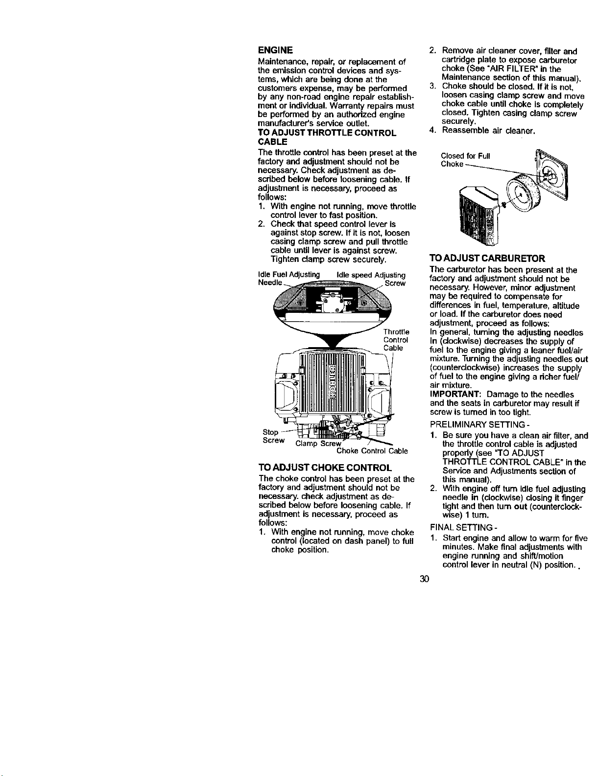
ENGINE
Maintenance, repair, or replacement of
the emission control devices and sys-
tems, which are being done at the
customers expense, may be performed
by any non-road engine repair establish-
ment or individual.Warranty repairs must
be performed by an autbedzed engine
manufacturer'sservice outlet.
TO ADJUST THROTTLE CONTROL
CABLE
The throttlecontrol has been preset at the
factory and adjustment should not be
necessary. Check adjustment as de-
scdbed below before loosening cable. If
adjustment is necessary, proceed as
follows:
1. With engine not running, move throttle
control lever to fast position.
2. Check that speed control lever is
against stop screw. If it is not, loosen
casing clamp screw and pull throttle
cable untillever is against screw.
Tighten clamp screw securely.
Idle Fuel Adjusting Idle speed Adjusting
Needle. Screw
Throttle
Control
Cable
Screw Clamp Screw
Choke Control Cable
TO ADJUST CHOKE CONTROL
The choke control has been preset at the
factory and adjustment should not be
necessary, check adjustment as de-
scdbed below before loosening cable. If
adjustment is necessary, proceed as
fellows:
1. With engine not running, move choke
control (located on dash panel) tofull
choke position.
2. Remove air cleaner cover, filter and
cartddge plate to expose carburetor
choke (See "AIR FILTER" in the
Maintenance section of this manual).
3. Choke should be closed. Ifit is not,
loosen casing clamp screw and move
choke cable untilchoke is completely
closed. Tighten casing clamp screw
securely.
4. Reassemble air cleaner.
Closed for Full
TO ADJUST CARBURETOR
The carburetor has been present at the
factory and adjustment should not be
necessary. However, minor adjustment
may be required to compensate for
differences in fuel, temperature, altitude
or load. If the carburetordoes need
adjustment, proceed as follows:
In general, turning the adjustingneedles
In (clockwise) decreases the supplyof
fuel to the engine giving a leaner fuel/air
mixture. Turningthe adjustingneedles out
(ceunterclockwise) increases the supply
of fuel to the engine givinga dcherfuel/
air mixture.
IMPORTANT: Damage to the needles
and the seats in carburetor may result if
screw isturned in tootight.
PRELIMINARY SETTING -
1. Be sure you have a clean airfilter, and
the throttle control cable is adjusted
propedy (see =TOADJUST
THROTTLE CONTROL CABLE" in the
Service and Adjustments section of
this manual).
2. With engine off turn idlefuel adjusting
needle in (clockwise) closingit finger
tight and then turn out (counterclock-
wise) 1 turn.
FINAL SETTING -
1. Start engine and allow to warm for five
minutes. Make final adjustments with
engine running and shift/motion
control lever in neutral (N) position..
3O
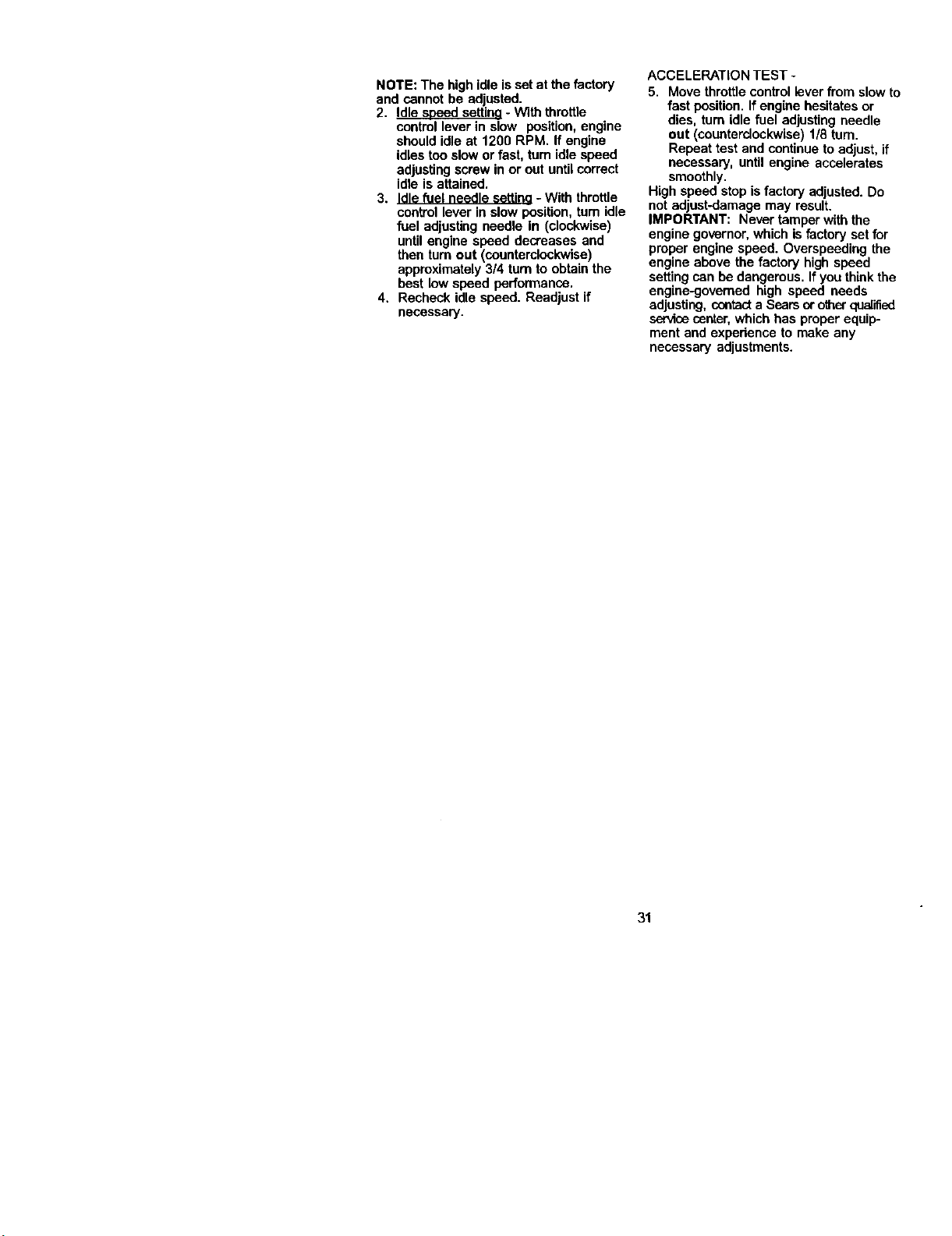
NOTE: The high idleis setat the factory
and cannot be adjusted.
2. Idle soeed settina - With throttle
control lever in slow position, engine
should idle at 1200 RPM. If engine
idles too slow or fast, turn idle speed
adjustingscrew in or out until correct
idle is attained.
3. Idle fuel needle settina- With throttle
control lever in slow position, tum idle
fuel adjusting needle in (clockwise)
untilengine speed decreases and
then turn out (counterclockwise)
approximately 3/4 turnto obtain the
best low speed performance.
4. Recheck idle speed. Readjust if
necessary.
ACCELERATION TEST -
5. Move throttle control lever from slow to
fast position. If engine hesitates or
dies, turn idle fuel adjustingneedle
out (counterclockwise) 1/8 turn.
Repeat test and continue to adjust, if
necessary, until engine accelerates
smoothly.
High speed stop isfactory adjusted. Do
notadjust-damage may result.
IMPORTANT: Never tamper with the
engine governor, which isfactory set for
proper engine speed. Overspeeding the
engine above the factory high speed
setting can be dangerous. If you thinkthe
engine<jovemed high speed needs
adjusting, contacta Searsor o_'_erqualified
servicecenter,which has proper equip-
ment and expedence to make any
necessary adjustments.
31

Immediately prepare your tractor for
storage at the end of the season or if the
tractor will not be used for 30 days or
more.
,_ CAUTION: Never store the tractor
with gasoline in the tank inside a building
where fumes may reach an open flame or
spark. Allow the engine to cool before
stodng in any enclosure.
TRACTOR
Remove mower from tractor for winter
storage. When mower is to be storedfor
a period of time, clean it thoroughly,
removeall dirt,grease, leaves, etc. Store
in a clean, dry area.
1. Clean entire tractor (See "CLEANING"
in the Maintenance section of this
manual).
2. Inspect and replace belts, if necessary
(See belt replacement instructions in
the Service and Adjustments section
of this manual).
3. Lubdcate as shown in the Mainte-
nance section of this manual.
4. Be sure that all nuts, bolts and screws
are securely fastened. Inspect moving
parts for damage, breakage and wear.
Replace if necessary.
5. Touch up all rusted or chipped paint
surfaces; sand lightly before painting.
BATTERY
• Fully charge the battery for storage.
• After a peded of time in storage, battery
may require recharging.
• To help prevent corrosion and power
leakage dudng long periods of storage,
battery cables should be disconnected
and battery cleaned thoroughly (see
"TO CLEAN BATTERY AND TERMI-
NALS" in the Maintenance section of
this manual).
• After cleaning, leave cables discon-
nected and place cables where they
cannot come in contact with battery
terminals.
• If battery isremoved from tractorfor
storage, do not store battery directly on
concrete or damp surfaces.
ENGINE
FUEL SYSTEM
IMPORTANT: It isimportant to prevent
gum deposites from forming in essential
fuel system parts such as carburetor,fuel
hose, or tank dudng storage. Also,
experience indicates that alcohol
blended fuels (called gasohol or using
ethanol or methanol) can attract moisture
which leads to separation and formation
of acids dudng storage. Acidic gas can
damage the fuel system of and engine
while in storage.
1. Drain the fuel tank.
2. Start the engine and let it run until the
fuel lines and carburetor are empty.
• Never use engine or carburetor cleaner
products in the fuel tank or permanent
damage may occur.
• Use fresh fuel next season.
NOTE: Fuel stabilizer is an acceptable
alternative in minimizing the formation of
fuel gum deposits dudng storage. Add
stabilizer to gasoline in fuel tank or
storage container. Always follow the mix
ratio found on stabilizer container. Run
engine at least 10 minutes after adding
stabilizer to allow the stabilizerto reach
the carburetor. Do not drain the gas tank
and carburetor if using fuel stabilizer.
ENGINE OIL
Drain oil (with engine warm) and replace
with clean engine oil. (See "ENGINE" in
the Maintenance section of this manual).
CYLINDER(S)
1. Remove spark plug(s).
2. Pour one ounce of oil through spark
plug hole(s) into cylinder(s).
3. Turn ignitionkey to "START" position
for a few seconds to distributeoil.
4. Replace with new spark plug(s).
OTHER
• Do not store gasoline from one season
to another.
• Replace your gasoline can if your can
startsto rust. Rustand/or dirtin your
gasoline will cause problems.
• If possible, store your tractorindoors
and cover it to give protectionfromdust
and dirt.
• Cover your tractor with a suitable
protective cover that does not retain
moisture. Do not use plastic. Plastic
cannot breathe which allows conden-
sation to form and will cause your
tractorto rust.
IMPORTANT: Never covertractor while
engine and exhaust areas are stillwarm.
32
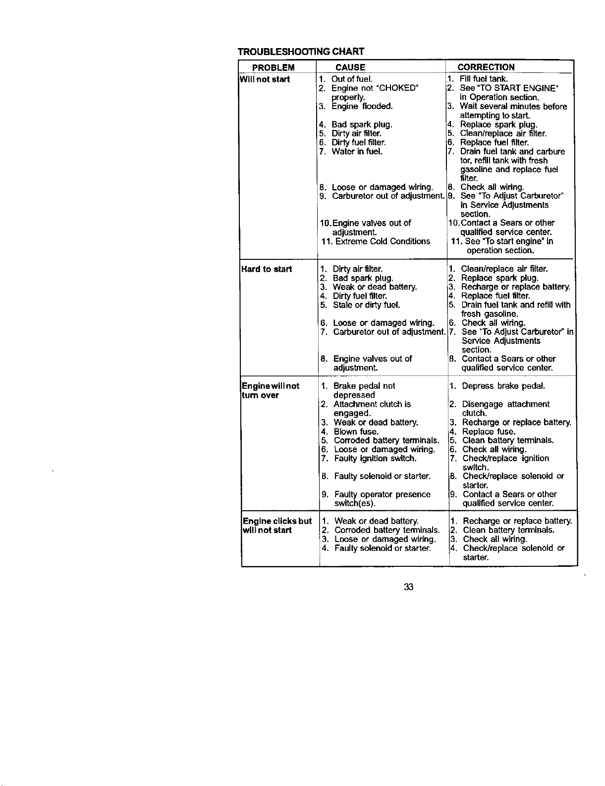
TROUBLESHOOTINGCHART
PROBLEM
Will not start
_lard to start
Enginewillnot
lure over
Engine clicks but
will not start
CAUSE
1. Out offuel.
2. Engine not =CHOKED°
properly,
3. Engine flooded.
4. Bad spark plug.
5. Dirty air tilter.
6. Dirty fuel tilter.
7. Water in fuel.
8. Loose or damaged wiring.
9. Carburetor out of adjustment.
10.Engine valves out of
adjustment.
11, Extreme Cold Conditions
1. Dirty airtilter.
2. Bad spark plug.
3. Weak or dead battery.
4. Dirty fuel tilter.
5. Stale or dirty fuel,
6. Loose or damaged widng.
7. Carburetor out of adjustment.
8. Engine valves out of
adjustment.
1. Brake pedal not
depressed
2. Attachment clutch is
engaged.
3. Weak or dead battery,
4. Blown fuse.
5. Corroded battery terminals.
6, Loose or damaged widng.
7. Faulty ignition switch.
8. Faultysolenoid or starter.
9, Faulty operator presence
switch(es).
1. Weak or dead battery.
2. Corroded battery terminals.
3. Loose or damaged wiring.
4. Faultysolenoid or starter.
CORRECTION
1. Fill fuel tank.
2. See "TO START ENGINE"
in Operation section.
3. Wait several minutes before
attemptingto start.
4. Replace spark plug.
5. Clean/replace air filter.
6. Replace fuel tilter.
7. Drain fuel tank and carbure
tor. refilltank with fresh
gasoline and replace fuel
filter.
8. Check all widng.
9. See "To Adjust Carburetor"
in Service Adjustments
section.
lO,Contact a Sears or other
qualified service center.
11. See "To start engine"in
operationsection.
1. Clean/replace air filter.
2. Replace spark plug.
3. Recharge or replace battery.
4. Replace fuel filter.
5. Drainfuel tank and refillwith
fresh gasoline.
6. Check all widng.
7. See =ToAdjust Carburetor" in
Service Adjustments
section.
8. Contact a Sears or other
qualified service center.
1. Depress brake pedal.
2. Disengage attachment
clutch.
3, Recharge or replace battery.
_.. Replace fuse.
5. Clean battery terminals.
5. Check all wiring.
7. Check/replace ignition
switch.
B. Check/replace solenoid or
starter.
9. Contact a Sears or other
qualified service center.
1. Recharge or replace battery.
2. Clean battery terminals,
3. Check all widng.
4. Check/replace solenoid or
starter.
33

TROUBLESHOOTING CHART
PROBLEM CAUSE
LossMpower 1. Cuffingtoomuchgms_
Excessive
vibration
Engine contin ues
to run when
operator leaves
seat with
attachment
clutch engaged
Poor cut - uneven
fast.
2. Throttle in "CHOKE"
position.
3. Build-up of grass, leaves
and trash under mower.
4. Dirty air filter.
5. Low oil level/dirty oil.
6. Faulty spark plug.
7. Dirtyfuel filter,
8. Stale or dirty fuel.
9. Water in fuel.
10.Spark plug wire loose.
11.Dirty engine air screen/fins.
12.Dirty/clogged muffler.
13.Loose or damaged wiring.
14.Carburetor out of
adjustment.
15.Engine valves outof
adjustment,
1. Worn, bent or loose blade,
2, Bent blade mandrel,
3. Loose/damaged part(s).
1. Faulty operator-safety
presence control system.
1. Wom, bent or loose blade.
2. Mower deck not level.
3. Buildup of grass, leaves,
and trash under mower.
4. Bent blade mandrel.
5. Clogged mower deck vent
from build-up of grass,
leaves, and trash around
mandrels.
CORRECTION
1. Set in "Higher Cut" position/
reduce speed.
2. Adjust throttlecontrol.
3, Clean underside of mower
housing.
4, Clean/replace air filter.
5. Check oil level/change oil.
6, Clean and regap or change
spark plug.
7. Replace fuel filter.
8, Drainfuel tank and refill
with fresh gasoline.
9, Drainfuel tank and
carburetor, refill tank with
fresh gasoline and replace
fuel filter.
10.Connect and tighten spark
plug wire.
11. Clean engine air screen/
fins.
12. Clean/replace muffler.
13.Check all widng.
14.See "To Adjust Carburetor"
in Service Adjustments
section.
15.Contact a Sears or other
qualified service center.
1. Replace blade.
Tighten blade bolt.
2. Replace blade mandrel.
3. Tighten loose part(s).
Replace damaged parts.
1. Check wiring, switches and
connections. If notcorrected
contacta Sears or other
qualified service center.
1. Replace blade. Tighten
blade bolt.
2. Level mower deck.
3. Clean underside of mower
housing.
4. Replace blade mandrel.
5. Clean around mandrels to
open vent holes.
34

TROUBLESHOOTING CHART
CAUSE CORRECTION
1. Remove obstruction,
PROBLEM
Vlower blades will
motrotate
Poor grass
discharge
Headlight(s) not
iworking
f so equipped)
Battery will not
charge
Loss of drive
Engine "backfires'
whentumlng
engine
"OFF"
1. Obstruction in clutch
mechanism,
2, Worn/damaged mower
ddve belt.
3. Frozen idler pulley.
4, Frozen blade mandrel.
1. Engine speed too slow.
2. Travel speed too fast.
3. Wet grass.
4. Mower deck not level.
5. Low/uneven tire air pressure,
6. Wom, bent or loose blade.
i7. Buildup of grass, leaves and
trash under mower.
B. Mower ddve belt wom.
9. Blades improperly installed.
10. Improper blades used.
11.Clogged mower deck vent
holes from buildup of
grass, leaves, and trash
around mandrels.
1. Switchis"OFF".
2. Bulb(s) burned out.
3. Faultylight switch.
4. Loose or damaged wiring.
5. Blown fuse.
1. Bad battery call(s).
2. Poor cable connections.
3. Faulty regulator
(if so equipped).
4. Faultyalternator.
1. Freewheel control in
"disengaged" position.
2. Motion drive belt wom,
damaged, or broken,
3. Air trapped in transmission
during shipment or
servicing.
1. Engine throttlecontrol not
set at "SLOW"
positionfor 30 seconds
before stopping engine.
2. Replace mower drive belt.
3. Replace idler pulley.
4. Replace blade mandrel.
1. Place throttlecontrol in
"FAST"position.
2. Shiftto slower speed.
3. Allow grass to dry before
mowing.
4. Level mower deck.
5. Check tires for proper air
pressure.
6. Replace/sharpen blade.
Tighten blade bolt.
7. Clean underside of mower
housing.
B. Replace mower drive belt.
;). Reinstall blades sharp edge
down.
10.Replace with blades listed
in this manual.
11.Clean around mandrels to
open vent holes.
1. Turn switch"ON".
2. Replace bulb(s).
3. Checldreplace light switch.
4. Check wiring and connec-
tions.
5. Replace fuse.
1. Replace battery.
2. Check/clean all connec-
tions.
3. Replace regulator.
4. Replace alternator.
1. Place freewheel control in
"engaged" position.
2. Replace motion drive belt.
3. Purge transmission.
1. Move throttle control to
"SLOW" position and allow
to idle for 30 seconds before
stopping engine.
35

NOTES
36
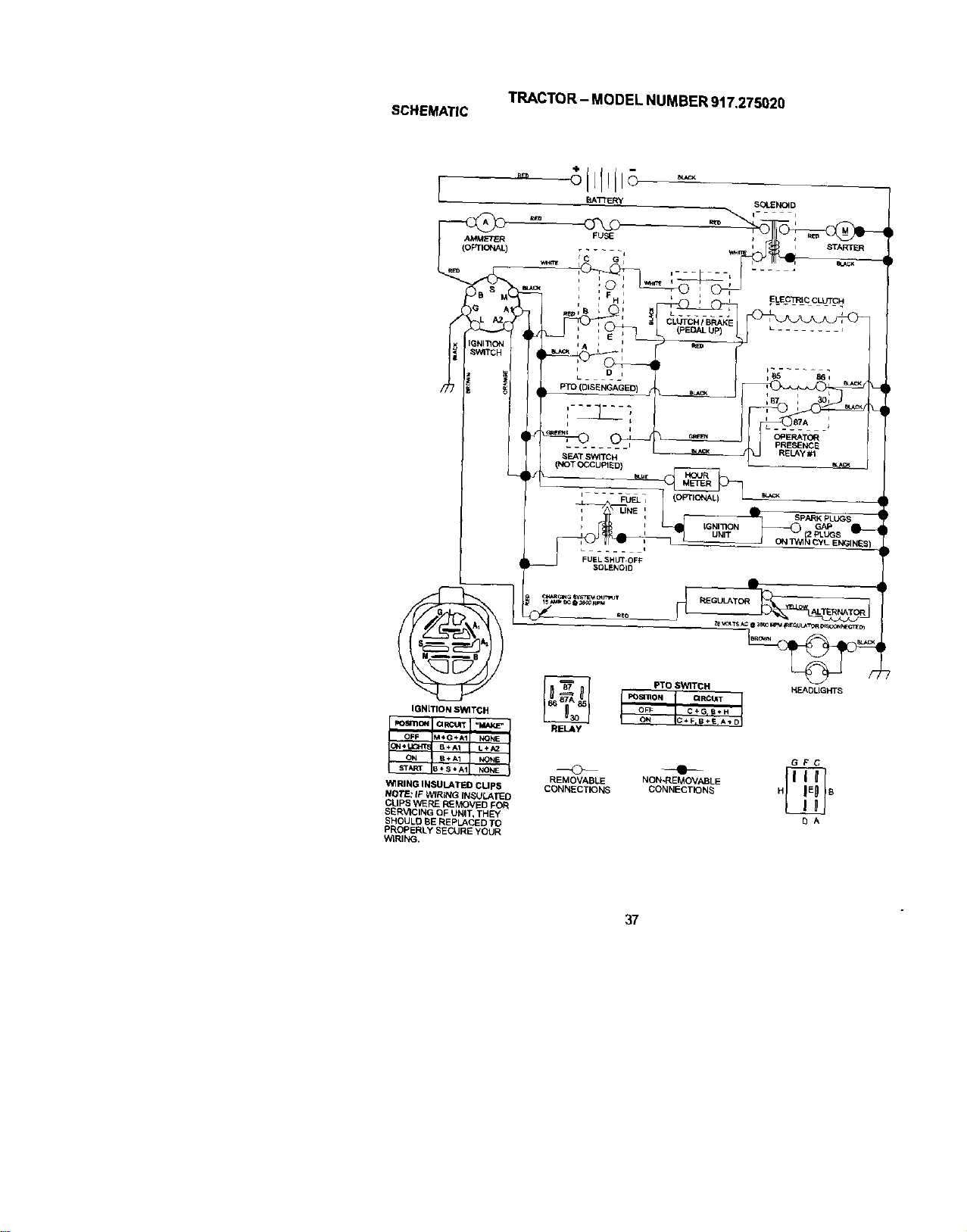
TRACTOR- MODELNUMBER917.275020
SCHEMATIC
BATTERY
IGNITION SWITCH
OFF M+G÷A1 ' NONE
ON÷ LIGHT 8+AI L+i_
ON # ÷A1 NONE
WIRING INSULATED CUPS
NOTE: IF WIRING IN_JLATEO
CUPS VV]ERE REMOVED FOR
SERVICING OF UNIT, THEY
S_OULD 1BEREPLACI_D TO
PROPBRLY SECURE YOUR
WIRING.
A
_EGULATOR_
PTO SWITCH HEADUGHTS
REMOVABLE
CONNECTK_NS
GFC
NON-REf_OVABLE
CONNECTIONS H B
SA
37
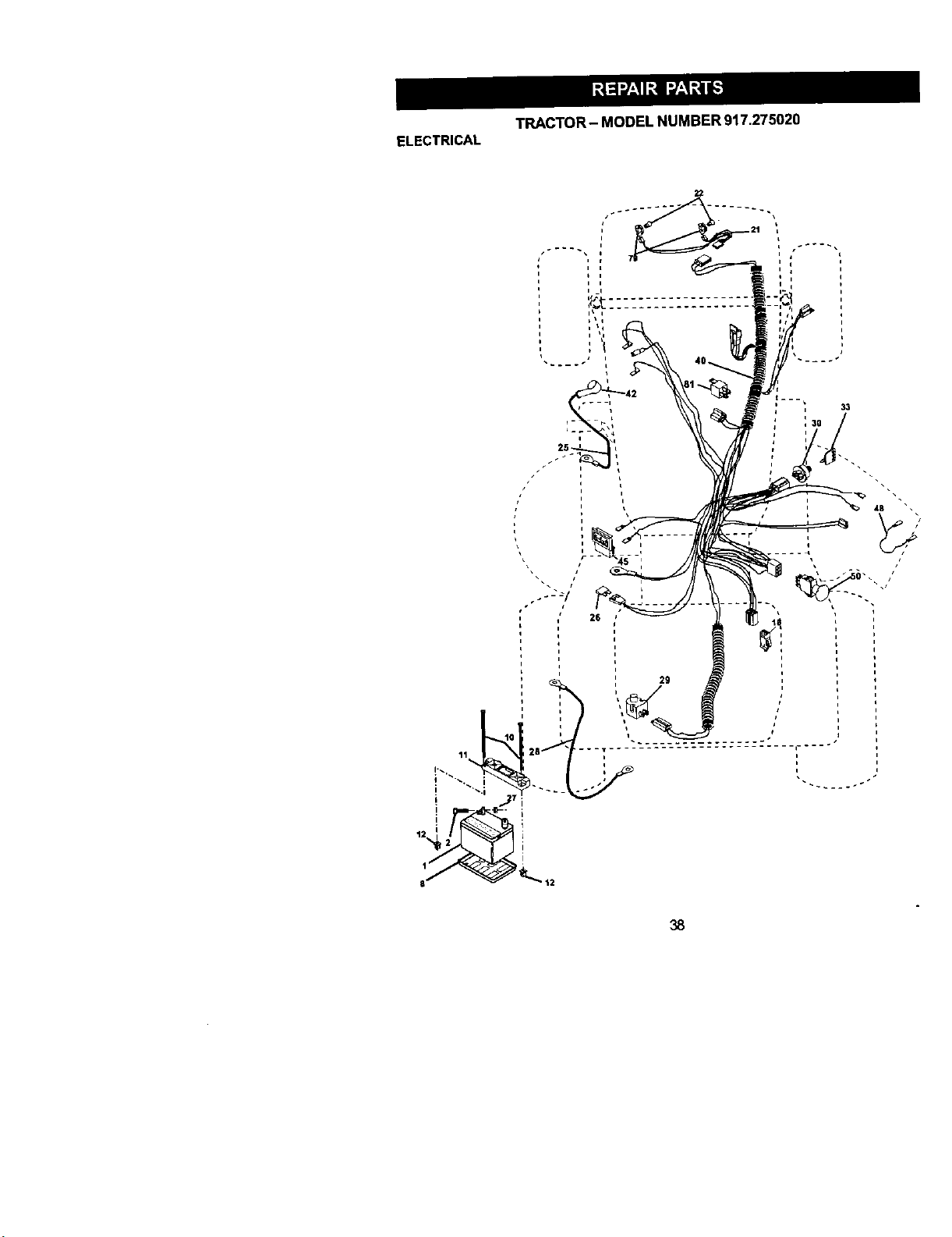
TRACTOR-MODELNUMBER917.275020
ELECTRICAL
4B
/
11
q"
[
26
i
J
i
i
i
38

TRACTOR- MODELNUMBER917.275020
ELECTRICAL
KEY PART
NO. NO. DESCRIPTION
1 144927 Battery
2 74760412 Boll Hex Head 1/4-30 X3/4
8 7603J Tray, Battery
10 145211 Bolt 114-20 x 7,5 Zinc
11 150109 Hold down Battery Dash Mount
12 145769 Nut Push Nylon 1/4"
16 153664 Switch Interlock Push-In
21 166184 Harness socket Light W/4152J
22 4152J BulbLight
25 150755 Cable, Battery
26 108824X Fuse
27 73510400 Nut Keps Hex 1/4-20 Unc
28 170697 Cable,Ground
29 160784 Switch,Plunger
30 175566 Switch, Ign
33 140403 Key, Ignitio_
40 170238 Harness Ign,
42 154336 Cover1Termir_t
45 122022X Ammeter
48 141940 protection Wire Loop
50 174652 Switch, PTO
79 163896 BulbhotderAsm Incandescent SV
81 109748X Relay Asm.
NOTE: All compor_nt dimensions given in U. S,
ir_hes 1 ii_ch= 25.4 turn
39

TRACTOR- MODELNUMBER917.275020
CHASSISANDENCLOSURES
4O
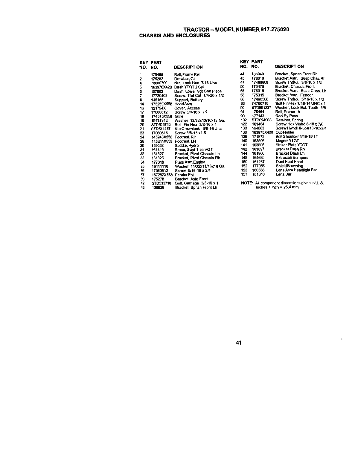
TRACTOR-MODELNUMBER917.275020
CHASSISANDENCLOSURES
KEY PART KEY PART
NO. NO. DESCRIPTION NO. NO. DESCRIPTION
1 175465 Rail, Frame RH 44 136940 Bracket, Spnsn Front Rh
2 175282 Drawbar,Gt 45 176018 Bracket Asrn., Susp Chas.Rh
4 73680700 Nut, Lock Hex 7116 Unc 47 174gC_o08 Screw Thdrol. 3/8-16 x 1/2
5 163976X420 Dash YTGT 2 Cyl 50 175476 Bracket, Chassis Front
6 157882 Dash, Lower Vgt One Piece 56 176016 Bracket Asm., Susp Chas. Lh
7 17720408 Screw, Thd Cut 114-20 x 1/2 58 175315 Bracket Asm,, Fender
8 145166 Support, Battery 68 17490508 Screw Thdrol 5118-18 x 1/2
14 175259)(558 Hood Asm 86 74760716 Bolt Fin Hex 7/16-14 UNC x 1
16 121794X Cover, Access 90 STD551237 Washer, Lock Ext. TOOth 3/8
17 17(60612 Screw 3/8-16 x .75 91 175464 Rail, Frame Lh
16 174515X558 Gdl_e 99 177143 Rod By pass
19 19131312 Washer 13/32x13/16x12Ga. 1(_ 8TD624003 Retainer, Spring
20 STD523710 Bolt, Fin Hex 3/8-16 x 1 122 161464 Screw Hex Wshd 8-18 x 718
21 STD541437 NutCroWrgock 3/8-16Unc 130 164863 ScrewHwhdHi-Lo#13*16x3/4
23 17060616 Screw318-18x1.5 138 163975)(428 CupHolder
24 145243)(558 FootreSt,RH 139 171873 BoltShoulder5116-18TT
28 145244X558 Footrest, LH 140 1638(;6 MagnetYTGT
30 145052 SaddLe,Hydro 141 163805 Striker Plate YTGT
31 161419 Brace, SLtpt1-pcVGT 142 161897 Bracket Cash Rh
32 161327 Br_ket, Pivot Chassis Lh 144 161900 Bracket Cash Lh
33 161326 Bracket, Pivot Chassis Rh 148 164655 ExtruslonBumpers
34 177018 plate Asm Engine 150 161237 Duot Heat Hood
35 19111116 Washer 11/32x11/16x16 Ga, 152 177956 ShieldBrowning
36 17060512 Screw 5/16-18x3/4 153 166568 LensAsmHeadlightBar
37 167287X558 FenderPnt 157 161840 LensBar
39 175278 Bracket, Axle Front
42 STD533710 Bolt, Carriage 3/8-16xl NOTE: AUcomponentdirnensionsgivenlnU. S.
43 136939 Bracket, Spnsn Front Lh inches 1 inch = 25.4 mm
41

TRACTOR- MODEL NUMBER 917.275020
GROUNDDRIVE
120
122_
33
144
07
t08
42
144
42
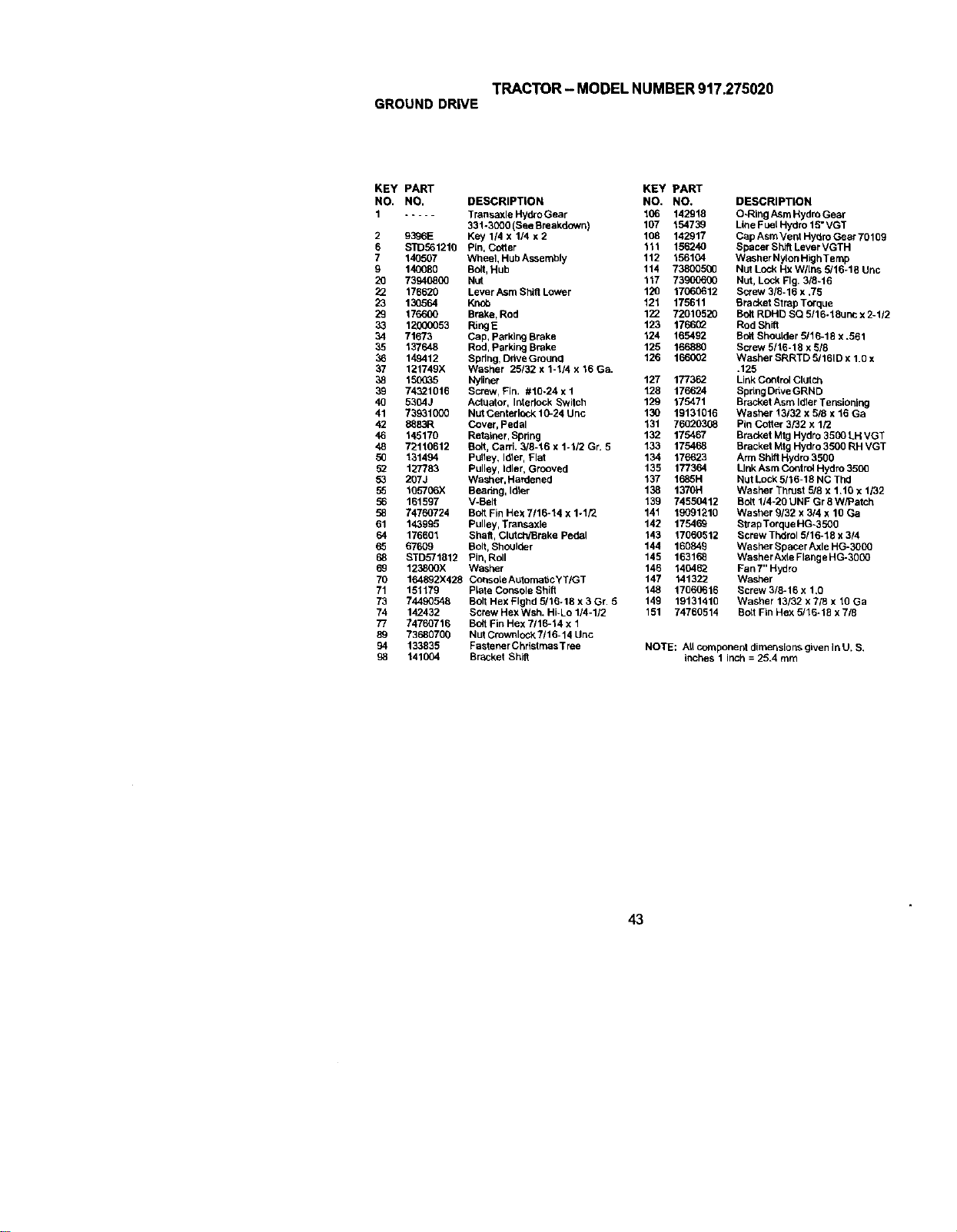
TRACTOR- MODELNUMBER917.275020
GROUNDDRWE
KEY PART KEY PART
NO. NO. DESCRIPTION NO. NO,
1 ..... Transaxle HydroGear 106 142918
331-3000 (See Breakdown) 107 154739
2 9396E Key 1/4 x 1/4 x 2 108 142917
6 S]_561210 Pin, Cotter 111 156240
7 140507 Wheel, Hub Assemoly 112 156104
g 140080 Bolt,Hub 114 73800500
20 73940800 Nut 117 73900600
22 176620 Lever Asm Shift LoWer 120 17060612
23 130564 Knob 121 175611
29 176600 Brake, Rod 122 72010520
33 12000053 RingE 123 176692
34 71673 Cap, Parking Brake 124 165492
35 137648 Rod, Parking Brake 125 166880
36 149412 Spdng, Ddve GrOUnCI 126 166092
37 121749X Washer 25/32 x 1-1/4 x 16 Ga.
38 150035 Nyllner 127 177362
39 74321016 Screw, Fin. #10-24 x 1 128 176624
40 5304J Actuator, laterlock Switch 129 175471
41 73931000 Nut Centerlock 10-24 Unc 130 19131016
42 8883R Cover, Pedal 131 769203G8
46 145170 Retatr_r, Spring 132 175467
48 72110612 Bolt, Carri. 3/8-16 x 1-1/2 Gr, 5 133 175468
50 131494 Pulley, Idler, Plat 134 176623
52 1LT/783 Pulley, Idler, Grooved 135 177364
53 267J Washer,Hardened 137 1685H
55 105706X Beadng, Idler 138 1370H
56 161597 V-Belt 139 74550412
58 74760724 Bolt Fin HexT/16-14 x 1-1/2 141 19091210
61 143995 Pulley, Transaxle 142 175469
64 176601 Shaft, Clutch/Brake Pedal 143 17060512
65 67609 Bolt, Shoulder 144 160849
68 STD571812 Pin, Roll 145 163168
69 123800X Washer 146 140462
70 1EA892X428 CorlsoleAutemattcYT/GT 147 141322
71 151179 PLateConsole Shift 148 17660616
73 74490548 Bolt Hex Flghd 5/16-18 x 3 Gr. 5 149 19131410
74 142432 Screw HexWsh, Hi-Lo 1/4-1/2 151 74760514
77 74760716 Bolt Fin Hex 7116-14 x 1
89 73680700 Nut Cmwnloak 7/16-14 Unc
94 133835 Fastener Christmas T tee
98 141004 Bracket Shift
DESCRIPTION
O-Ring Asm Hydro Gear
Line Fuel Hydro 15" VGT
Cap Asm Vent Hydro Gear 70109
Spacer Shift Lever VGTH
W_her Nylon High Temp
Nut Lock Hx Wllns 5/16-18 Unc
Nut, Lock Fig. 3/8-16
Screw 3/8-16 x ,75
Bracket Strap Torque
Bolt RDH[_ SQ 5116-18unc x 2-1/2
Rod Shift
Bolt ShouLder5115-18 x .561
Screw 5/16-18 x 9/8
Washer SRRTD 5/161D x 1.0 x
,125
LinkCo_ltrolClutch
Spdng Ddve GRND
Bracket Asm Idler Tensioning
Washer 13132 x 5/8 x 16 Ga
Pin Cotter 3/82 x 1/2
Bracket Mtg Hydro 3500 LH VGT
Bracket Mtg Hydro 3500 RH VGT
Arm Shift Hydro 3500
Llak Asrn Cordrol Hydro 3500
Nut Lock 5116-18 NC Thd
Washer Thrust 518x 1.10 x 1/82
Bolt 1/4-20 UNF Gr 8 W_atch
Washer 9132 x 3/4 x 10 Ga
Strap Torque HG-3500
Screw Thdrol 5/15-18 x 3/4
Washer SpacerAxle HG-3000
Washer Axle Flange HG-3O00
Fan 7" Hydro
Washer
Screw 3/8-16 x 1,0
Washer 13/32 x 7/8 x 10 Ga
Bolt Fin Hex 5/16-18 x 7/8
NOTE: Art component dimensions given inU. S,
inches 1 inch = 25.4 mm
43
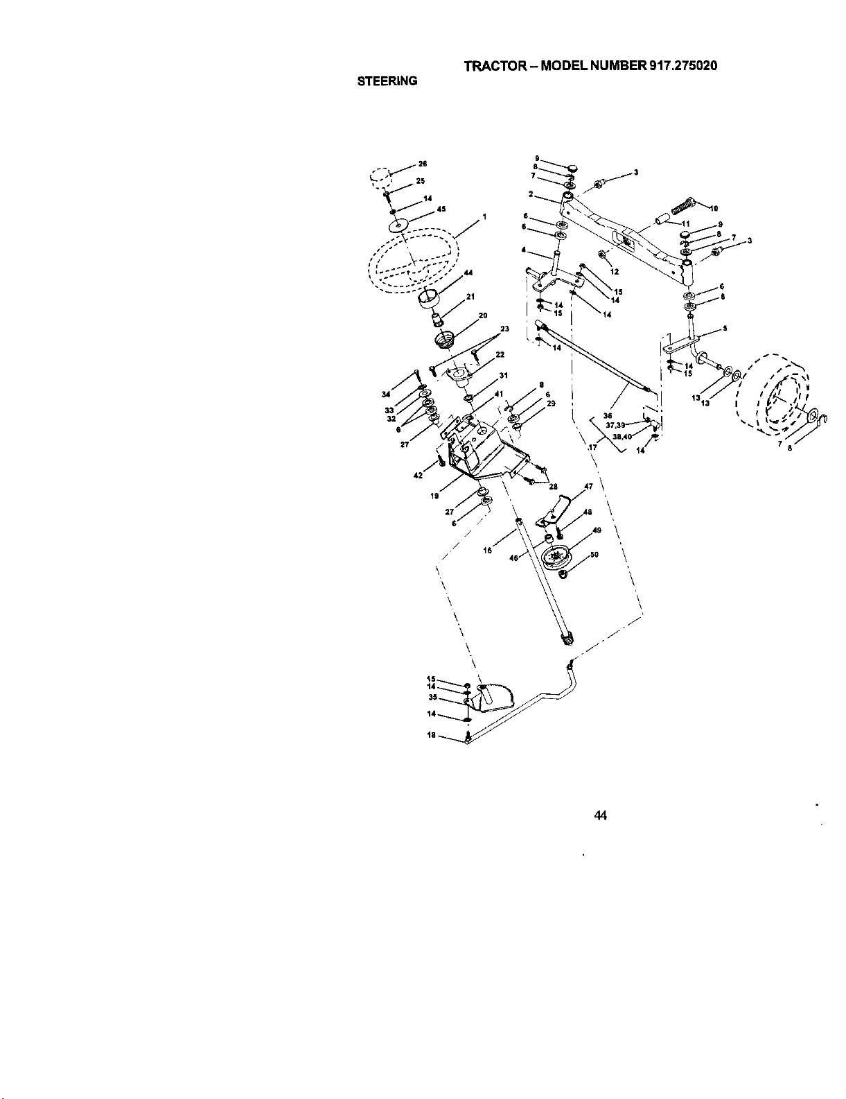
TRACTOR - MODEL NUMBER 917.275020
STEERING
45 1
32
27
42
IS
i
23
22
I
\
\
1313"
I
%
7
6
/
16
/
\
\
\
\
\ F
\ F
14
'\
\
44

TRACTOR- MODEL NUMBER 917.275020
STEERING
KEY PART
NO. NO. DESCRIPTION
1
2
3
4
5
6
7
8
9
10
11
12
13
14
15
16
17
18
19
2O
21
22
23
25
26
27
28
29
31
32
33
34
35
36
37
38
39
40
41
42
44
45
46
47
48
49
5O
159944X428 Wheel,Steering
137094 Axle Asm., Fror_t
5O55M Fitting, Grease
161849 Spindle Asm, LH
161848 Spindle Asm., RH
62O6H Bearing, RaCeThrust Harden
121748X Washer 25132 x 1-5/8 x 16 Ga.
1200C029 Ring,Klip#T5304-75
121232X Cap,Spindle
74781044 Bolt, Fin Hex 5/8-11 x 2-3/4
136518 Spacer Bearing Axle Front
739010(0 Nut, Lock Flange 5/8-11 Unc
121749X Washer 25/32 x 1-114 x 16 Ga,
STD551137 Washer, Lock Hvy Hlcl Spr 3/6
STD541537 Nut, Lock Center 318-24 UNF
145103 Shaft/_sm., Steedng
137347 Rod Asm., Tie Ball J Ball Vgt (Inc. Key No. 3640)
175572 Draglink Vgt
156011 Support Asm., Steedng Vgt
163887X428 Boot, BteeSng
159945 Adapter, Wheel Steering
155105 Bushing, Stlg. BIk
152927 Screw
74780616 Bolt, Fin Hex 3/8-16 x 1 Gr, 5
159946X428 Cap, Wheel Steeheg
335OR Bearing, Cot. Strg.
17000612 Screw, 3/8-16 x 3/4
104239X Bearing,Flange
138136 Bushing, Nyliner Sr_p
19111610 Washer 11/32 x 1 x 10 Ga,
STD551131 Washer, Lock Hvy Hlcl Spr 5/16
74780512 Bolt Fin Hex 5/16-18unc x 3/4
138(]59 Gear, Sector Steering
137156 Tie Rod
73360600 Jam NUt RH Thread
10965OX JointAsm. Ball RH Thread
73700600 Jam Nut LH Thread
1(}9651X Joint Asm, Ball LH Thread
155246 BraCket Switch Interlock VGT 97
17490508 Screw Thdrol 5116-16 x 1/2 Tyt
160135X428 Extension, Steering
19132411 Washer 13/32 x 1-1/20 x 11 Ga.
178291 Spacer .407 x .625 x .500
177863 Bracket Asm Idler Stationary
17060612 Screw 3/8-16 x .75
131494 Pulley Idler Fiat
739(]0690 NutLock Fig 3/8-16 UNC
NOTE: All component dimensions given in U. S.
inches 1 inch = 25.4 mm
45
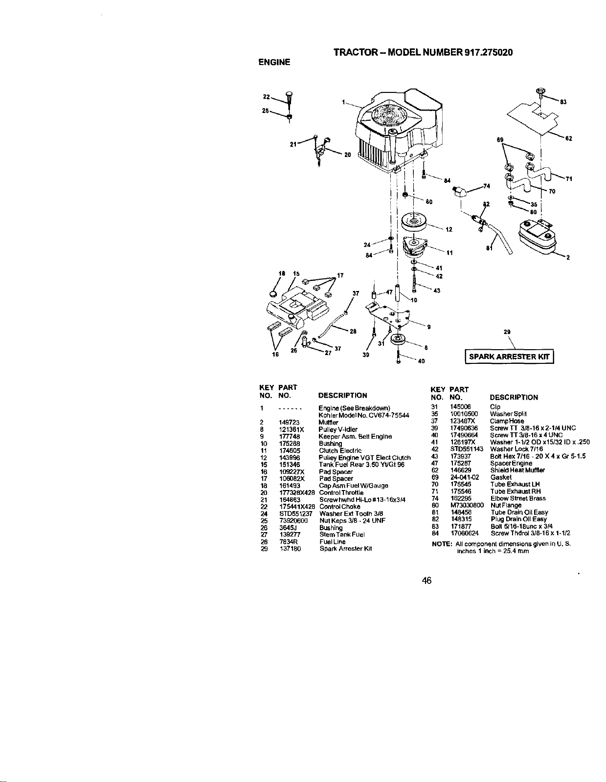
TRACTOR-MODELNUMBER917.275020
ENGINE
25
2t "_ 20
18 15 rl 7
16
89
39
29
\
J SPARK ARRESTER Kff J
KEY PART
NO. NO.
1 ......
2 149723
8 121361X
9 177748
10 175288
11 174605
12 143996
15 151346
16 109227X
17 106082X
18 161493
20 177328X428
21 164883
22 t75441X428
24 STD551237
25 73620600
26 3645J
27 139277
28 7834R
29 137180
OESCRIPTION
Engine (SeeBreakdown)
Kohler Model No. CV674-75544
Mu{fler
Pulley V-Idler
Keeper Asm. BeLtEngine
Bushing
Clutch Electric
Pulley Engine VGT Elect Clutch
Tank Fuel Rear 3,50 Yt/Gt 96
Pad Spacer
Pad Spacer
Cap Asm FuelW/Gauge
ControlThrcttle
Screw hwhd HkLo # 13-16x3/4
Contrc4Choke
W_isher Ext Tooth 3/8
Nut Keps 3/8 - 24 UNF
BUshing
Stern Tank Fuel
Fuel Line
Spark Arrester Kit
KEY PART
NO. NO. DESCRIPTION
31 145006 Clip
35 10010500 Washer Split
37 123487X CtampHose
39 17490636 Screw TT 3/8-16 x 2-114 UNC
40 17490664 Screw TT 3/8-16 x 4 UNC
41 126197X Washer 1-112OD x15/32 ID x ,250
42 STD551143 Washer Lock 7/16
43 173937 Bolt He)( 7/16 - 20 X 4 x Gr 5-1.5
47 175287 Spacer Engine
62 146629 Shield Heat Muffler
69 24_41_2 Gasket
70 175545 Tube Exhaust LH
71 175546 Tube Exhaust RH
74 162295 Elbow Street Brass
80 M73030800 Nut Flange
81 148456 Tube Drain Oil Easy
82 148315 Plug Drain OilEasy
83 171877 5olt 5/16-18unc x 3/4
84 17060624 Screw Thdro1318-16 x 1.112
NOTE: All component dimensions given in U. S.
inches 1 Inch = 25.4 rnm
46
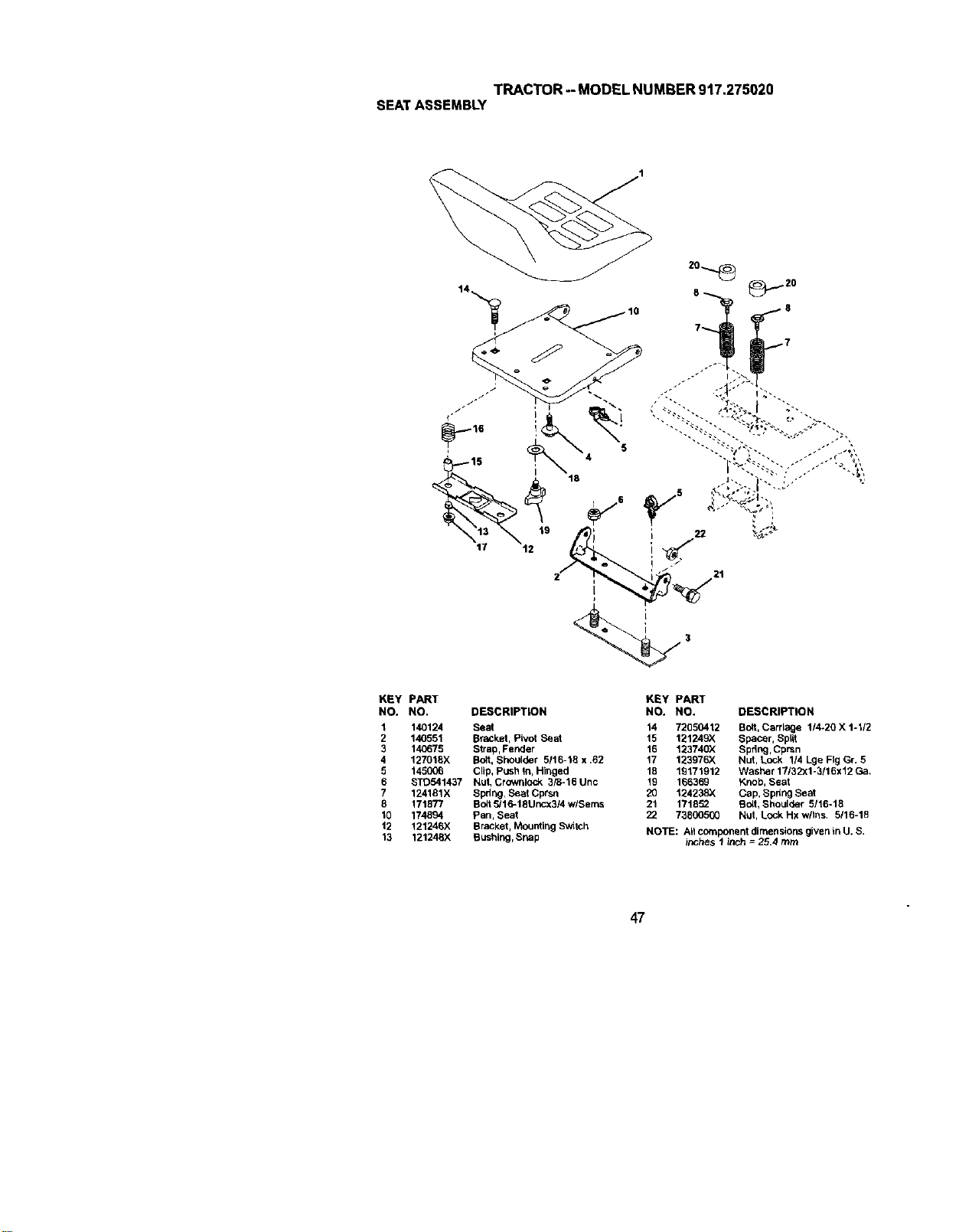
SEATASSEMBLYTRACTOR- MODELNUMBER917.275020
; o
KEY PART
NO. NO. DESCRIPTION
1 140124 Seat
2 140551 BraCkat, Pivot Seat
3 140675 Strap, Fetter
4 127018X So,_t,Shoulder 5/t6-15 x .62
5 145006 Clip_Push in,Hinged
6 STD541437 Nut, Crowrdock 3/B-16 Uric
? 124181X
Sprlr_glSeat Cprsn
8 171877 Bolt _/16-18Uncx3/4 w/Sems
_0 174894 Pan, Seat
12 121246;( Bracket, Mourdir_gSWitch
13 121248X Bushing, Snap
KEY PART
NO. NO. DESCRIPTION
14 72050.412 {]oft, Carriage 1/4-20 X 1-1/2
15 121249X
Spacer, Spl_
16 1_3740X Spring, Cprsn
17 1;_3971_K NLJt,Lock 1/4LgeF_gGr. 5
18 1_171912 Washer17J32Xl-3/16x12Ga,
19 166369 Knob, Seat
20 124238X Cap, Spdng Seat
21 171852 So_t,Shoulder 5/16-18
22 738005GO N_Jt,Lock Hx w/iris. 5116-18
NOTE: AII component dinlens_orts given inU. S,
inches I inch = 25.4 mrn
47

TRACTOR-MODELNUMBER917.275020
DECALS
18
17
6 3
15 15
17
22
KEY PART KEY PART
NO. NO, DESCRIPTION NO. NO.
1 164094 Decal Dash 13 177542
2 149516 Decal Battery DNGR/PSN 14 175291
ENGAsm 15 177415
3 171702 Decal Hood RH Crattsman 17 177375
4 171703 Decal Hood LHCraftsman 18 164065
5 140837 Decal Brake Parking Saddle 19 138047
6 133644 Decal Maintenance 22 166960
7 177416 Decal Engine 23 1C_02X
8 164884 Decal Blower HsngKohl -- 157199X428
9 163204 Decal, Fender Crallsman -- 138311
10 156439 DecalFender Danger
11 177781 DecaIFTREST - - 177758
12 177554 Decal V-Belt Dr Sch - - 177759
12
DESCRIPTION
Decal Replacement
Decal V-Belt Schem
Decal HoodSide Pnl
Decal Dash Panel
Dec_ Insert Strg
Decal Battery
DecalDrawbarCNTRL
Reflectro, Tai_light
Pad Footrest
Decal Handle Ltt Height
Adjust (LiftHandle)
Owner's Manual, English
Owner's Manual, Spanish
4
10
KEY PART
NO. NO. DESCRIPTION
1 59192 CapValve Tire
2 65139 Stem Valve
3 106228X427 Rim Asm Front
4 9134H Tube, Front (Service Item Only)
5 105588X Tire, Front
6 278H FittingGrease (FrontWbeel Only)
7 9040H Beadng Flange(Front Wbeel Only)
8 104757X428 Cap Axle (Front Wheel Only)
9 106230:( TireRear
10 7154J Tube Rear (Service Item Only)
11 106277X427 RirnAsm Rear
12 6856M Fit6ngGrease
- - 144334 Sealant, Tire ( 10 oz. Tube)
NOTE: Atlcomponent dimensions given in U. S.
inches 1 inch = 25.4 mm
48

LIFT ASSEMBLY
40
39
TRACTOR- MODEL NUMBER 917.275020
43
35 73
11 23
7O
KEY PART
NO. NO.
1 121006X
2 177535
3 159189
4 12000022
5 19292016
6 71110624
7 175830
8 175831
9 122364X
10 2876H
11 175375
12 163552
15 STD541437
16 674A247
18 143363
19 STD551037
20 5328J
21 STD523710
23 STD624008
24 73350800
26 73680800
29 150233
76 "_26
75
Z3
DESCRIPTION
Rod Asm,, Lever
Shaft Asm., Lift Vgt
Lever Asm., Lift Rh
E-Ring Truarc#5133-87
Washer 29132 x 1-1/4 x 16 Ga.
Bolt, Fin Hex 3/8-16 x 1-1/2
Grip, Handle Fluted
Button, Plunger
Ptunger, Button
Spring 2-1/8"
Link Lift
RetainerSpring
Nut, Crownlock 3/8-16 Unc
Spring Asm., Assist Lift
Bracket, Sphag Assist
Washer 13132 x 13/16 x 16 Ga,
Boit, Adjust Spring Assist
Boit, Fin Hex 3/8-16 x 1
Retainer, Spring
Nut, Jam Hex 1/2-13 Unc
NutCrownlock 1/2-13 Unc
Trunnion, Infin Height
KEY PART
NO. NO. DESCRIPTION
30 11(_07X Nut, Special
31 STD551037 Washer 13132 x 5/8 x 16 Ga.
32 137150 Spring, Compression Inf Hgt
33 STD560907 Pin, Cotter 3/32 x 112
34 137167 Rod, Adj Lift
35 138057 Knob, Inf 3/8-16 Uric
38 155097 Pointer, Height Indicator
39 123935X PLug,Hole
40 17060516 Screw Hex Wsh 5116-18 x 1
41 175994 Nut, Lift Link 7/16-20
42 19112410 Washer 11/32 x 1-1/2 x 10 Ga,
43 123934X Scale, Indicator Height
70 145212 Nut Hex Flange Lock
72 110452X Nut Push phos & Oil
73 73350600 Nut Hex Jam 3/8-16 UNC
74 175802 Arm Susp. Rear RH
75 175805 Plate Asm. Susp. Front
76 175560 Pin, Range
77 176205 Trunoion Susp. Arm
70 175689 Trunnion Susp. Front
79 175378 Arm, susp, R LH
NOTE: All component dimensions g{ven inU. S,
inches 1 inch = 25.4 mm
49

TRACTOR- MODELNUMBER917.275020
MOWERDECK
46
50

TRACTOR- MODEL NUMBER 917.275020
MOWERDECK
KEY PART KEY PART
NO. NO. DESCRIPTION NO, NO,
1 174377 Deck Weldment Mower 48 48 174368
3 138017 Bracket Asm., Sway Bar 49 73680600
5 493_M Ratalner Spdng 50 72110612
6 130832 Arm, Suspension, Rear (_vay 5_ 175820
Bar) 56 1559_
8 174365 Bolt 7/16 ._sm. Blade 57 156941
11 173920 Blade 97 133943
13 175147 Shaft Asrn. w/Lower Beartr_j 98 174370
14 174358 HouslngMandre_ 99 175080
15 110485X Beadng, Betl,Mandret 100 73110616
16 174493 StripperMandret Deck 107 175294
17 72110610 Bolt RDHD Sq Neck 3/8o16 x 1.25 108 721104G8
18 72140505 Bolt, Carriage 5116o18x 5/8 109 73680400
19 132827 Bolt, Hex Hd, Shoulder 5116-18 110 175016
20 174378 Baffle, Vodex Mower 111 174610
21 73680500 Nut, Crowniock 5/16-18 UNC 113 72110508
24 105304X Cap, Sleeve 116 137644
25 178013 Spdng,Torsion 117 174873
26 110452X NUt, Push 118 739306(_
27 174346X428 DetlectorShleld 119 19121414
28 19111016 Washer 11132 x 5/8 x 16 Ga. 121 174371
29 131491 Rod, Hinge 126 174372
30 157722 Screw, Thdmll Washer Head 130 17060616
31 129963 Washer, Spacer Mower Ventad 131 19131606
32 177865 Polley, Marbdrel - - 175396
33 178342 NUt, Fig. Top Lock Cntr. 9/16
36 19131316 Washer 13132 x 13116 x 16 Ga.
37 173437 Pulley, Idler, Flat
39 174375 Pulley, idler, Ddven
42 165723 Spacer, Retainer - - 174357
43 174373 Arm, idler Secondary
45 174343 Cover, Mandret Deck
46 137729 Screw, Thdroll. 1/4-20 x 5/9
47 174369 V-Belt, Mower, Secondary
DESCRIPTION
V-Belt, Mower, Primary
Nut, Crownlock 3/8-16 UNC
Bolt, CarT. 3/8-16 x 1-112 Gr. 5
Pulley Idler Rat
Bar Pnt Adj.
Pin Head Rivet
Washer Hardened
Spdng Pnmary Dnve
pufiey IdLer"V_
BORRDHD Sqnk 3/8-16 UNC x 2
Baffle Vac Edge Mower
Bolt Carr.
NUt Crownlock 1/4-20
Arm Spdng Secondary
Arm Spring Fixed Tension
Bolt Cart, 5116-18 x 1
Bad,Shoulder
Gauge Wheel,Wide
Nut, Centerlock 3/8-16 UNC
Washer 3/8 x 7/8 x 14 Ca.
Sprir_gSecondary DriVe
Arm, Idler, Pdrnary Deck
Screw 3/8-16 x 1.0
Washer 13/32 x 1/4 x 16 Ga.
Deck Complete (Std. Deck-
Order separately mulcher
plate and gauge wheel
components Key Nos. 101-106
arid 116÷118)
Mandret Asm. Service
(_nclades Key Nos. 13-15)
NOTE: All component dimensions given in U. S.
inches 1 inch = 25.4 mm
51

TRACTOR-MODELNUMBER917.275020
TRANSAXLE-MODELNUMBER331-3000
i

TRACTOR- MODEL NUMBER 917.275020
TRANSAXLE-MODEL NUMBER331-3000
KEY pART KEY PART
NO. NO. DESCRIPTION NO. NO. DESCRIPTION
1 161122 Main Housing Assembly 74 169535 Ball Brg 6205-1
2 178317 R.H. Housing Assembly 75 161157 Seal l"ld X 2.0472" X
3 169522 Center Section Assembly 0.375"
4 161125 Spacer 76 161153 Shaft, Axle
5 142932 Seal-Lip 77 142884 Washer
6 142928 Wire Retaining Ring 79 178322 Gasket Material
7 142933 Retaining Ring 80 161159 Torx Head Screw, 5/16-18
8 142934 Ball Beadng 81 161160 Needle Bearing (Sce1412)
9 169523 CradLe Bearing 82 161161 Washer2
10 169524 Variable Swashpl_late 83 161162 Retaining Ring
11 150771 Thrust Bearing 30 84
X 52 X 13 161163 Lip Seal
12 161126 Input Shaft (6.875LD.X1.3o.D.X0.25
13 142978 Block Thrust Washer 85 161164 Brake Disk
14 142977 Arm-Trunnion 87 178323 Washer
15 196050 10cc Cylinder Block 88 178324 Screw 5/16-24
Assembly 89 178325 Bearing
21 169525 21cc Cytlnder Block 90 178326 Spacer
Assembly 91 169536 Oring, 0.070 X 0.239
24 161127 Output (Motor) Shaft 92 178327 Screw
25 169526 Thrust Beadng 42 X 68 X 16 93 142969 Spring, Fdctlon pack
26 161128 Control Arm 94 142980 Spacer, Friction Pack
27 161129 SD;acer 95 169537 Hex Lock Nut 5116-24
28 161130 l_t Pinion Gear 96 169538 Sleeve Bearing
29 169527 Capscrew, M6 X 1-22 97 150798 Oil
30 142941 Slot Guide 106 161166 Spacer, Trunnion
31 161132 Trunnion Arm 108 178328 Plug
32 161133 Trunnion Bushing 110 142918 FItting-O Ring Ass'y
33 142946 Lip Seal 111 142917 Cap Vent Ass'y
34 178318 Arm Return 116 169539 Retaining Ring
36 178319 Arm Actuating 117 161168 Std Hdls Pin
36 169528 5/16-24 Stud 120 142883 Puck, Brake
37 142967 Puck, FdcBon 121 169546 Rib Neck Bolt, 2"
38 150787 Bypass Plate 122 178329 Brake Yoke
39 169529 Bypass Actuator 124 178330 Arm, Brake
40 142945 Lip Seal 125 142887 Pins, Brake
41 142952 Bypass Arm 126 161172 Lockwasher, 1/4"
42 142953 Retaining Ring 127 161173 Nut, 1/4-20
43 142966 Pin 128 142885 Nut, Castle
44 150797 Screw 129 142886 Cotter Pin
48 178320 Puck 130 161174 Spacer
50 178343 Screw-Self Tapping 131 142882 Puck Plate
61 169530 Lower Cover 132 169544 Rib Neck Bolt, 3" 1
52 169531 Gerotor Assembly 134 178331 Spring
53 144581 O-Ring 136 178332 Spring Extension
54 161139 Gerotor Cover 137 178333 Pin Spdng
55 178321 Filter 138 178334 Bolt Se Talf pplng
56 169533 Charge Manifold 139 161176 Washer, 7/8o(:1 X 6.265id X
57 161142 Retainer, Motor Bearing 0.128 Thk
58 161143 Pin, Cantar 141 178335 Spring Brake
59 161144 15t Planet Gear 144 169545 O Ring, 2.864 Id X 0.676
60 161145 7t Spur Gear Thk
61 161146 21t Bun Gear 148 169546 Spring, Rellaf
62 161147 Planet Thrust Plate 146 169547 Ball, 7/16
63 161148 51t Ring Gear 151 161181 Comp. Spring, Brake Anti-
64 161149 Planetary Career Drag
65 161156 Miter Gear, Diff. (Splined) 152 178336 Brake Pull Rod
66 161151 Miter Gear, D_. 153 142914 Plug, Straight Thread
67 161152 Shaft, Differential 155 178337 Kit Fan
66 161153 Diff. Thrust Plate 157 169548 Screw O-Ring
69 169534 Flange Bearing 180 169549 Manifold Kit
76 161154 Washer 263 178338 Kit Seal
71 161155 Washer 960 166773 Transaxle, complete
73 161156 Hex Jam Nut, 8/8-18
NOTE: All component dimensions given in U.S.
inches 1 inch = 25.4 mm
53
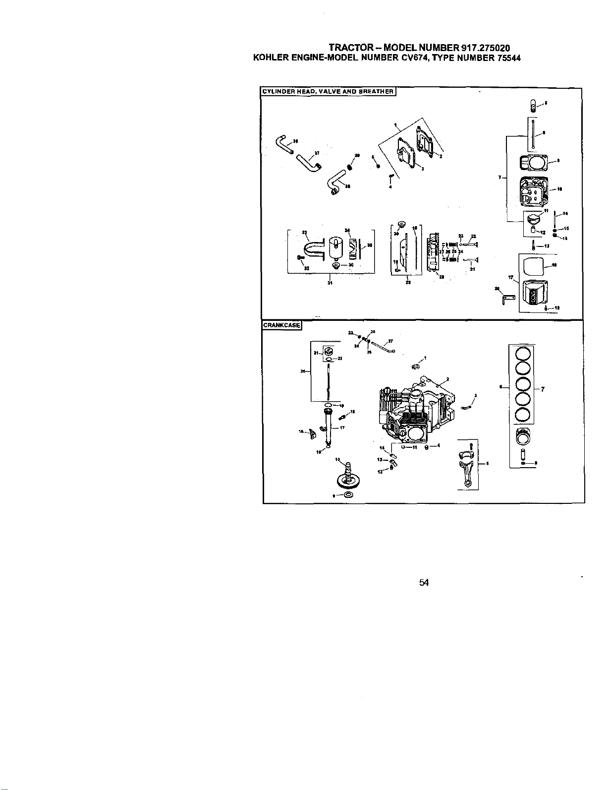
TRACTOR- MODEL NUMBER 917.275020
KOHLERENGINE-MODELNUMBERCV674,TYPE NUMBER75544
CYLINDER HEAD, VALVE AND BREATHER I
T- _--te
1--13
©
©
I-- O -7
©
©
0
54
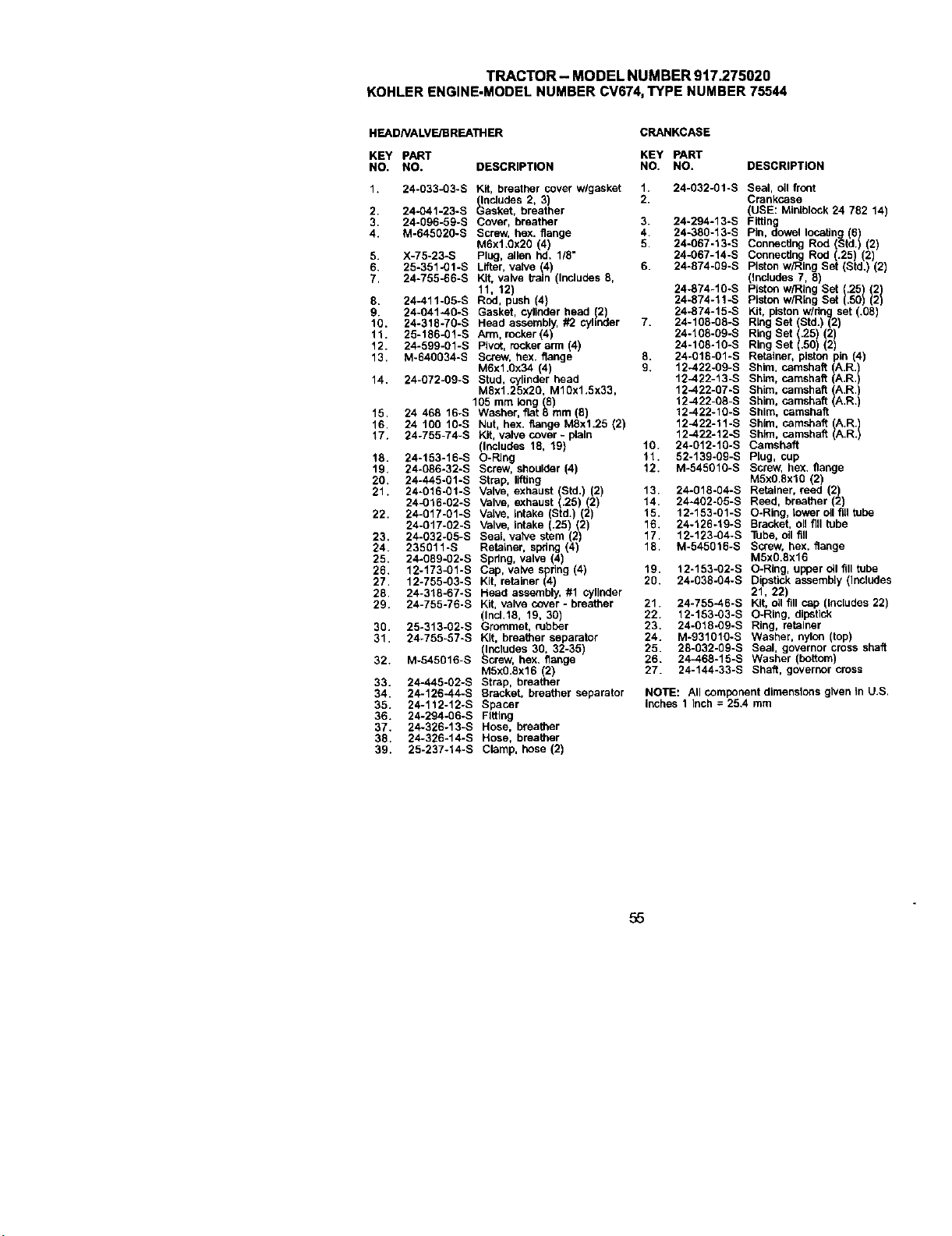
TRACTOR- MODEL NUMBER 917.275020
KOHLERENGINE-MODELNUMBERCV674,TYPE NUMBER75544
HEADNALVF.JBRP-ATH ER
CRANKCASE
KEY PART KEY PART
NO. NO. DESCRIPTION NO. NO. DESCRIPTION
1. 24-033-03-S Kit, breather cover wlgasket 1. 24-032.01-S Seal, oil front
_lncludes 2, 3) 2. Crankcase
2 24-G41-23-S uasket, breather (USE: Miniblock 24 782 14)
3, 24-096-59-S Cover, breather 3. 24-294-13-S Fitting
4. M-645020-S Screw, hex. flange 4 24-380-13-S Pin, dowel locating (6)
M6xl.gx2O (4) 5 24.067-13-S Connectthg Rod (Std.) (2)
5. X-75-23-S Plug, allen hd. 1/8" 24-067-14-S Connecting Rod (.25) (2)
6. 25-351-01-S Lifter, valve (4) 6. 24-874.09-S Piston w/Rlog Set (Std.) (2)
7, 24-755-86-S Kit, valve train (Includes 8, includes 7, 8
11,2 g.,,10sPistonw logSet1201
8. 24-411.05-S Rod, push (4) 24-874-11 -S piston w/Ring Set .50
9. 24-041-40-S Gasket, cylinder head (2) 24-874-15-S Kit piston w/dng set (.08)
10. 24-318-70-S He_d assem_y, #2 cytk_er 7. 24-108-88-S Rlog Set (Std.) (2)
11. 25-186-01-S Arm, rocker (4) 24-108-09-S Ring Set (.25 (2)
12. 24-59g-01-S Pivot, rocker arm (4) 24-108-10-S Ring Set (.50) (2)
13. M-640034-S Screw, hox. flange 8. 24-018-01-S Retainer, piston pin (4)
M6x1.Ox34 (4) 9, 12-422.09-S Shim, camshaft (A.R.)
14. 24-072-09-S Stud, cylinder head 12--422-13-S Shim, camshaft (A.R.)
MBx1.25x20, M1Ox1,5x'33, 12-422-gT-S Shim, camshaft (A.R._
105 mm long (8) 12-422-08-S Shim, camshaft (A.R.)
15. 24 468 16-S Washer, fiat 8 mm (8) 12-422-1g-s Shim, camshaft
16, 2410010-S Nut, hex. flange M8x1.25 (2) 12-422-11-S Shim, camshaftlA /
17. 24-755-74-S Kit, valve cover - plain 12-422-12-S Shim, camshaft IRRI
(Includes 18, 197 10. 24-012-10-S Camshaft
18. 24-153-16-S O-PJng 11. 52-139-09-S Plug, cup
19. 24-056-32-S Screw, shoulder (4) 12. M-545010-S Screw, hex. flange
20, 24-445-01-S Strap, lifting M5x0.Bxl0 (2
21. 24-016-01-S ValVe, exhaust Std. (2 13. 24-018-04-S Retainer, reed 2
24-016-02-S ValVe, exhaust .25 2 14. 24-402-05-S Reed, breather (2)
22. 24-_7*0%S VaLve, k_ake (Std.'J _2'_ 15. 12-153-01-S O-Ring, tower oil fill tube
24-017-02-S Valve, Intake (25) (2) 16. 24o126.19.S Bracket, oll fill tube
23. 24-032.05-S Seal, valve stem (2) 17. 12o123-04-S Tube, oil fill
24. 235011-S Retainer, spring (4) 18. M-545016-S Screw, hex. flange
25. 24-089-02-S Spdng, valve 4 M5x0.8x16
26. 12-173-01-S Cap, valve spdng (4) 19. 12°153-02-S O-Rlog, upper oll fill tube
27. 12-755-03-S Kit, retainer (4) 2g. 24-038-04-S D_sgc.k assembly _lP_udes
28. 24-318-67-S Head assembly, #1 cylinder 21, 22)
29. 24-755-76-S Kit, valve cover - breather 21. 24-755-46-S Kit, oll fill cap (Includes 22)
(Ind.18, 19, 30) 22. 12-153-03-S O-Ring, dipstick
30. 25-313-02-S Grommet, rubber 23. 24-018-09-S Ring, retainer
31. 24-755-57-S Kit, breather se arator 24. M-931010-S Washer, nylon (top)
(Includes 30, 3_35) 25. 28-032.09-S Seal, governor cross shaft
32. M-545016-S Screw, hex. flange 26. 24-468-15-S Washer (bottom)
M5X0.8x16 (2) 27. 24-144-33-S Shaft, governor cress
33. 24-445-02-S Strap, breather
34. 24-126-44-S Bracket, breather separator NOTE'. All component dimensions given in U.S.
35. 24-1_2-12-S Spacer inches 1 Inch = 25.4 mm
36. 24-294.06-S Fitting
37. 24-326-13-S Hose, breather
38. 24-326-14-S Hose, breather
39. 25-237-14-S Clamp, hose (2)
55

TRACTOR- MODELNUMBER917.275020
KOHLERENGINE-MODELNUMBERCV674,TYPENUMBER75544
GNITIONIELECTRICAL I
@
\x.___ _"
AIR INTAKE J
BLOWER HOUSING AND BAFFLES J
0--$
'\ I
56
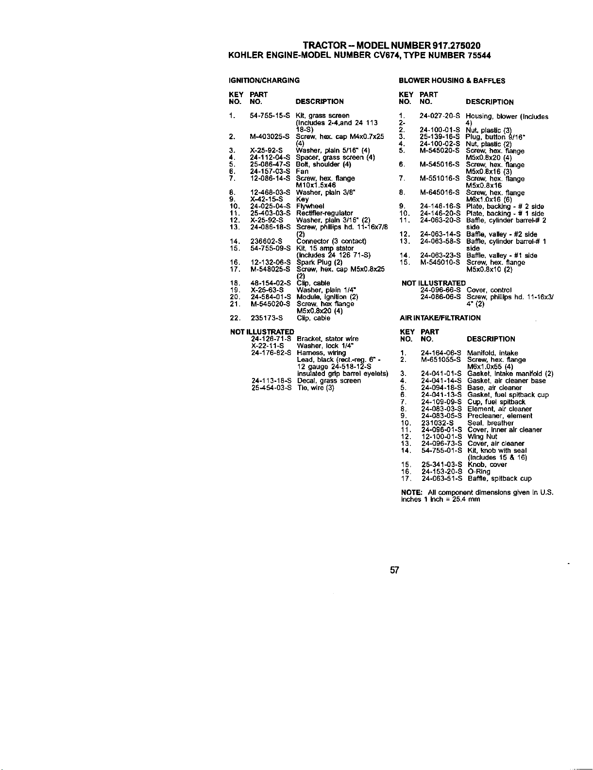
TRACTOR-MODELNUMBER917.275020
KOHLERENGINE-MODELNUMBERCV674,TYPENUMBER75544
IGNITION/CHARGING
BLOWER HOUSING & BAFFLES
KEY PART KEY PART
NO. NO. DESCRIPTION NO. NO. DESCRIPTION
2,
3.
4.
5.
6.
7.
8,
9.
10.
11.
12.
13.
14.
15.
16.
17.
18.
19,
20,
21,
54-755-15-S Kit, grass screen 1. 24-027-20-S Housing, blower (Includes
(Includes 2-4,and 24 113 2- 4)
18-S) 2. 24-100-01-S Nut, plastic (3)
M-403025-S Screw, hex. cap M4xO.7x25 3. 25-139-16-S Plug, button 9/16"
(4) 4. 24-100-02-S Nut, plastic (2)
X-25-92-S Washer. pleln 5/16" 4) 5. M-545020-S Screw, hex. flange
24-112-04-S Spacer. grass screen (4) MSx0.8x20 (4)
25-086-47-S Bolt, shoulder (4) 6. M-545016-S Screw, hex, flange
24-157-03-S Fan M5x08x16 (3)
12-086-14-S Screw. hex, flange 7. M-551016-B Screw, hex. flange
M10x1.5x46 M5xg.8x16
12-468-03-B Washer, plain 3/8" 8. M-645016-B Screw. hex. flange
X-42-15-S Key M6x1.0x16 (6
24-025-04-S Flywheel 9. 24-146-16-S Pae, backng - # 2 side
25--403-03-S Rectifier-regulator 10. 24-146-20-S Plate, backing - # 1 side
X-25-92-S Washer, pleln 3/16" (2) 11. 24-063-20-S Baffle, cylinder barrel-# 2
24-086-18-S Screw, phillips hd. 11-16x7/8 side
(2) 12. 24-063-14-B Baffle. valley - #2 side
236602-S Connector (3 contact) 13, 24-063-58-S Baffle. cylinder barrek# 1
54-755-09-S Kit, 15am=p st_tor side
(Includes 24 126 71-S) 14. 24-063-23-S Baffle. valley - #1 side
12-132-06-S Spark Plug (2) 15. M-545016-S Screw, hex. flange
M-548025-S Screw, hex. cap M5x0.8x25 M5xg,8xl0 (2)
(2)
48.154-02-S Clip, cable NOT ILLUSTRATED
X-25-63-S Washer. plain 1/4" 24-096-66-S Cover, control
24-584-01-B Module. IgnlUon (2) 24-086-06-S Screw, phiUlps hd, 11-t6x3/
M-545020-S Screw, hex flange 4" (2)
M5xO.6x2O (4)
235173-S Clip, calve AIR INTAKEtlFILTRATION
22.
NOT ILLUSTRATED
24-126-71-S Bracket. stator wire
X-22-11-S Washer, lock 114"
24-176-82-B Harness. widng
Lead, black (rect.-reg. 6" -
12 gauge 24-518-12-S
insulated grip hen'el eyelets)
24-113-18-S Decal, grass screen
25-454-03-S Tie, wire (3)
KEY PART
NO. NO. DESCRIPTION
1, 24-164-06-S Manifold, intake
2. M-651055-S Screw. hex. flange
M6x1,0x55 (4)
3. 24-041-01-S Gasket, Intake manifold (2)
4, 24-041-14-S Gasket, air cleaner base
5, 24-094-18-S Base, air cleaner
6 24-041-13-S Gasket, fuel spitback cup
7. 24-109-09-S Cup, fuel spltback
8. 24-083-03-S Element. air cleaner
9. 24-083-05-S Preoleaner, element
10. 231032-S Seal, breather
11. 24-096-01-S Cover, inner elr cleaner
12. 12-100-01-S Wing Nut
13. 24-096-73-S Cover, air cleaner
14. 54-755-01-S Kit, lomb with seal
(Includes 15 & 16)
15. 25-341-03-S Knob. cover
16. 24-153-20-S O-Ring
17, 24-063-51-S Baffle, spltback cup
NOTE: All component dimensions given In U.S.
Inches 1 inch = 25,4 mm
57

TRACTOR - MODEL NUMBER 917.275020
KOHLERENGINE-MODELNUMBERCV674,TYPE NUMBER75544
STARTING SYSTEM I
/
ENGINE CONTROLS i_
_u
OIL PAN I LUBRICATION I
,,J=
I
_7
58
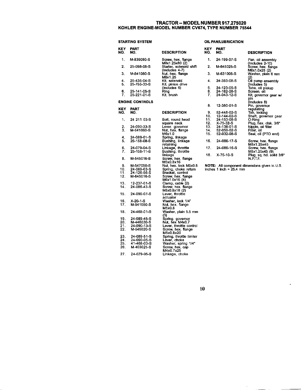
TRACTOR-MODELNUMBER917.275020
KOHLERENGINE-MODELNUMBERCV674,TYPENUMBER75544
STARTING SYSTEM
KEY PART
NO. NO.
1. M-839080-S
2. 25-098-08-S
3. M-841080-S
4. 25-435-04-S
5. 25-755-33-S
6, 25-141-05-S
7. 25-221-01-S
ENGINE CONTROLS
KEY PART
NO. NO.
1. 24 211 03-S
2. 24-090-33-S
3. M-641060-S
4. 24-089-01-S
5. 25-158-08-S
6. 24-079-04-S
7. 25-158-11-S
8. M-545016-S
9. M-547050-S
10. 24-089-03-S
11. 24-126-56-S
12. M-645016-S
13. 12-237-01 -S
14. 24-086-43-S
15. 24-090-07-S
16, X-20-1-S
17. M-541050-S
18. 24-468-01-S
19, 24-089-45-S
20. M-446030-S
21. 24-0g0-13-S
22. M-545020-S
23. 24-089-51-S
24. 24-090-05-S
25. 41-468-03-S
26. M-403025-S
27. 24-079-05-S
OIL PANILUB RICATIO N
KEY PART
DESCRIPTION NO. NO. DESCRIPTION
Screw, hex. flange 1. 24-199-07-S
M8xl,25xS0 (2)
Starter, solenoid shift 2. M-645025-S
(Includes 4-7)
Nut, hex. flange 3. M-631005-S
M8x1.25
Kit, solenoid 4. 24-393-08oS
Kit, pinion ddve
(Includes 6) 5. 24-123-05-S
Ring 6. 24-162-26-S
Kit, brush 7. 24-043-12-S
DESCRIPTION
Bolt, round head
square neck
Lever, govemor
NUt, hex. flange
M6x1.0
Spdng, linkage
Bushing, linkage
retaining
Linkage, throttle
Bushing, throttle
linkage
Screw, hex. flange
M5x0.8x16
Nut, hex. lock M5x0.8
Spdng, choke return
Bracket, control
Screw, bex. flange
M6x1.0x16 (4)
Clamp, cable (2)
Screw, hex. flange
M5x0.8x16 (2)
Lever, throttle
actuator
Washer, lock 1/4"
NUt, hex. flange
M5x0.8
Washer, plain 5.5 mm
(3)
Spring, governor
NUt, hex M4x0.7
Lever, throttle control
Screw, hex. flange
M5x0.8x20
Spdng, throttle limiter
Lever, choke
Washer, spring 1/4"
Screw, hex. cap
M4X0.7X25
Linkage, choke
8, 12-380-01-S
9. 52-448-02-S
10. 12-144-02-S
11. 24-153-08-S
12. X-75-32-S
13, 24-136-01-S
14. 52-050-02-S
15. 52-032-08-S
Pan, oll assembly
_ncludes 2-10)
crew, hex, flange
M6x1,0x25 (2)
Washer, plain 6 mm
_2_ pump assembly
(Includes 5)
Tube, oil pickup
Screen, oil
Kit, governor gear w/
,in
Includes 8)
Pin. governor
regulating
Tab, Iockthg
Shaft, governor gear
O-Ring
Plug, hex. ctsk. 3/8"
Nipple, oil filter
Fifler, oil
Seal, oil (PTO end)
16. 24-086-17-S Screw, hex. flange
M8x1.25x45
17. 24-086-16-S Screw, hex. flange
M8x1.25x45 (9)
18. X-75-10-S Plug, sq. hd. solid 3/8"
N.RT.F.
NOTE: Allcomponent dimensionsgiven in U.S.
inches 1 inch= 25.4 mm
59
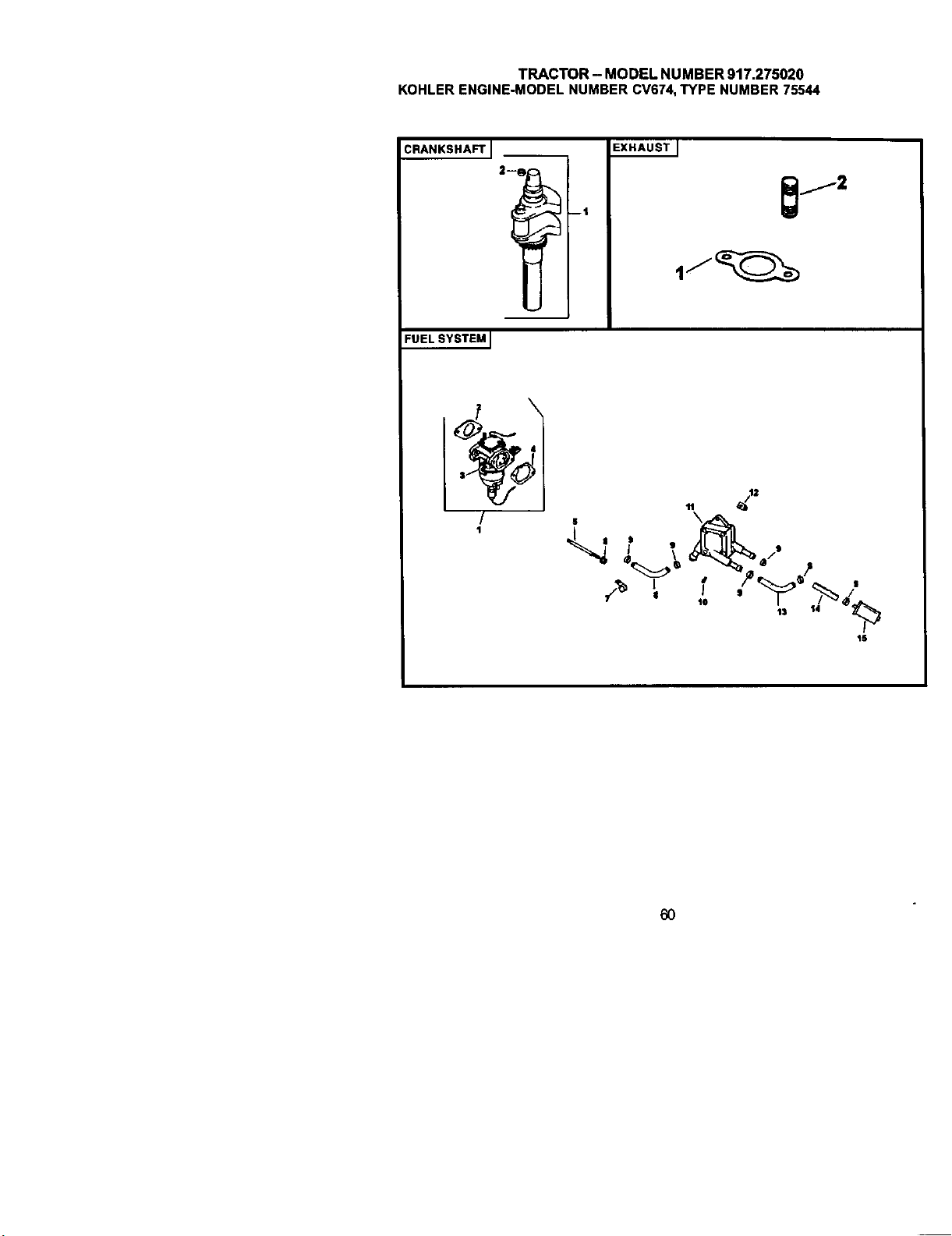
TRACTOR - MODEL NUMBER 917.275020
KOHLERENGINE-MODELNUMBERCV674,TYPE NUMBER75544
CRANKSHAFT J
FUELSYSTEM I
--I
EXHAUSTJ
11
S
I
15
60
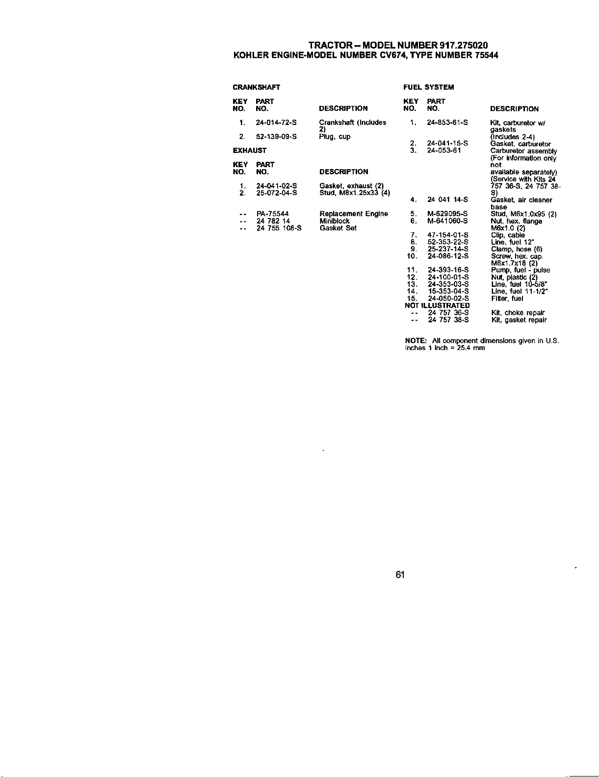
TRACTOR- MODEL NUMBER 917.275020
KOHLERENGINE-MODELNUMBERCV674,TYPE NUMBER75544
CRANKSHAFT
KEY PART
NO, NO. DESCRIPTION
I. 24-014-72-S Crankshaft (Includes
2)
2 52°139-09-S Plug, cup
EXHAUST
KEY PART
NO. NO. DESCRIPTION
I. 24-041-02-S Gasket. exhaust (2)
2. 25-072-04-S Stud. M8xf.25x33 (4)
- - PA-75544
-- 24 782 14
°- 24 755 108-S
Replacement Engine
Mtoiblock
Gasket Set
FUEL SYSTEM
KEY PART
NO. NO,
1. 24-853-61-S
2. 24-041°15oS
3. 24-053-61
4. 24 041 14-S
5. M-629095-S
6. M-641060-S
7. 47-154-gl-S
8. 52-353-22-S
9, 25-237-14-S
10. 24-0fl6-12-S
11. 24-393-16-S
12. 24-100÷01-S
13. 24-353-g3-s
14. 15-353-04-S
15. 24-050-02-S
NOT ILLUSTRATED
-- 24757 36-S
-- 24 75738-S
DESCRIPTION
Kit, carburetor wl
gaskets
_ndudes 2-4)
asket, carburetor
Carburetor assembly
(For Information only
not
available separately)
(Service with Kits 24
757 36-S, 24 757 38-
S)sket, air cleaner
base
Stud, M6xl.Oxg5 (2)
Nut, hax. flange
M6x1.0 (2)
Clip, cable
Line, fuel 12"
Clamp, hose (6)
Screw, hex. cap.
M6x1.7x18 2
Pump, fuel - pu se
Nut, plastic 2
Line, fuel 1(_-_18"
Line, fuel f1-1/2"
Filler, fuel
Kit, choke repair
Kit, gasket repair
NOTE: All component dimensionsgiven in U.S.
Inches I inch = 25.4 mm
61

NOTES
62
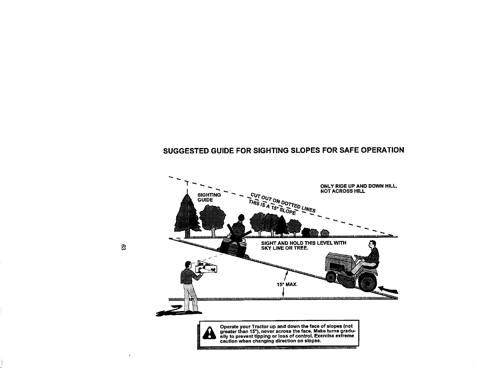
SUGGESTED GUIDE FOR SIGHTING SLOPES FOR SAFE OPERATION
ONLY RIDE UP AND DOWN HILL,
NOT ACROSS HILL
! /_ Operate your Tractor up and down the face of slopes (not I
greater than 15 ), never across the face. Make turns gradu- I
ally to prevent ttpping or loss of control. Exercise extreme
caution when changing direction on elopes. I

Forrepairofmajorbrandapptiancesinyourown home...
nomatterwhomadeit,nomatterwhosolditJ
1-800-4-MY-HOME _ AnyOne,dayor_1_
(_-800-_S3) (U.S._.andCa'ada)
Wt,_wJ_eal_,Colll www.f_all_a
Forrepairofcarry-inproductslikevacuums,lawnequipment,and
electronics,callfor thenearestSearsPartsand RepairCenter.
1-800-488-1222 Any_me,dayorrk_t(U,SAody)
www.se61_,cofn
Forthereplacementparts,accessoriesandowner'smanuals
thatyouneed todo-it-yourself,callSearsPartsDirectS"!
1-800-366-PART
(1-_o-3_-7278)
6a.m.- 11p.m., 7days aweek
(u.s._.onty)
w,w_,r.ears._,_att,d_,t
To purchaseor inquireaboutaSearsServiceAgreement
orSearsMaintenarv_ Agreement:
1-800-827-6655 (U.S.A.) 1-800-361-6665 (Canada)
7 a.m.- 5p_n.,CST,Men.- SaL 9 a.m.- 8p.m.EST, M- F,4p.m.Sat.
Parapedrseniledere_ a
domldio,yparaordenarp_zos:
1.888.SU.HOGAR_
(1-888-784-6427)
¢ Se_r_RoebuckandCo.
® Registered Trademark I TM Trademark I SMService Mark o! Seam, Roebuck and Co.
® Marca Registrada I TMMarca de F_bdca / sMMama de Sefvido de Seam, Roebuck and Co
McMarque de commerce / MeMarque d_pos_e de Seam, Roebuck and Co.
177758 2.15.01 JH Printed in U.S.A.


