Loading ...
Loading ...
Loading ...
Installation Instructions
INSTALL THE RANGE (CONT.)
[] COOKTOP BURNERS
[] ASSEMBLING THE BURNERS
CAUTION: Theelectrodeofthe
spark igniter is exposed. Be careful not to
snag the electrode of the spark igniter with
a cleaning cloth. Damage to the igniter could
occur. Be careful not to turn on any cooktop
controls while cleaning. A slight electrical
shock might result, which could cause you
to knock over hot cookware.
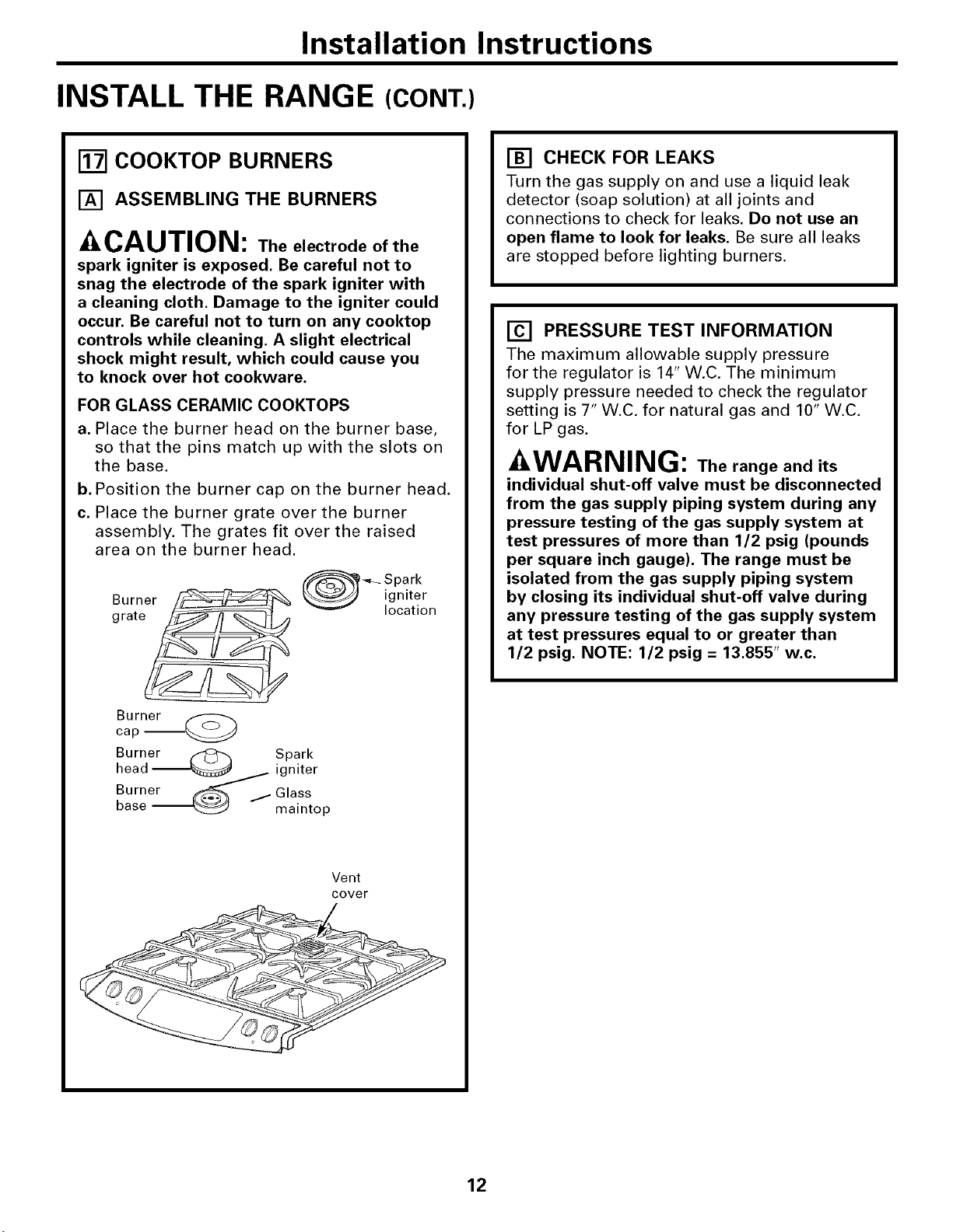
FOR GLASS CERAMIC COOKTOPS
a. Place the burner head on the burner base,
so that the pins match up with the slots on
the base.
b. Position the burner cap on the burner head,
c. Place the burner grate over the burner
assembly. The grates fit over the raised
area on the burner head.
Burner
grate_
Burner
cap --_
_-_ Spark
_ igniter
v location
Burner _ Spark
head - _ igniter
Burner _ Glass
base _ maintop
Vent
cover
[] CHECK FOR LEAKS
Turn the gas supply on and use a liquid leak
detector (soap solution) at all joints and
connections to check for leaks. Do not use an
open flame to look for leaks. Be sure all leaks
are stopped before lighting burners.
[] PRESSURE TEST INFORMATION
The maximum allowable supply pressure
for the regulator is 14" W.C, The minimum
supply pressure needed to check the regulator
setting is 7" W.C, for natural gas and 10" W.C,
for LP gas.
-&WARNING: The range and its
individual shut-off valve must be disconnected
from the gas supply piping system during any
pressure testing of the gas supply system at
test pressures of more than 1/2 psig (pounds
per square inch gauge). The range must be
isolated from the gas supply piping system
by closing its individual shut-off valve during
any pressure testing of the gas supply system
at test pressures equal to or greater than
1/2 psig. NOTE: 1/2 psig = 13.855" w.c.
12
Loading ...
Loading ...
Loading ...