Operator's Manual /
Sit
CUTOFF SAW
Model No.
351.268500
CAUTION: Read and follow
all Safety Rules and Operating
Instructions before First Use
of this Product.
Sears, Roebuck and Co., Hoffman Estates, IL 60179 U.S.A.
www, sears.condcraftsman
17682.02 Draft (09/20/02)
Warranty .................................. 2
Safety Rules .............................. 2-3
Unpacking ................................. 3
Installation ............................... 3-4
Operation ................................. 4
Maintenance ............................... 5
Troubleshooting ............................. 6
Parts Illustration and List .................... 8-9
EspaSol ............................... 10-15
FULL ONE YEAR WARRANTY
ifthis product fails due to a defect in material or work-
manship within one year from the date of purchase,
Sears will at its option repair or replace it free of
charge. Contact your nearest Sears Service Center
(1-800-4-MY-HOME) to arrange for product repair, or
return this product to place of purchase for replace-
ment.
If this product is used for commercial or rental purpos-
es, this warranty will apply for 90 days from the date of
purchase.
This warranty applies only while this product is used in
the United States.
This warranty gives you specific legal rights and you
may also have other rights which vary from state to
state.
Sears, Roebuck and Co., Dept. 817WA, Hoffman
Estates, IL 60179
WARNING: For your own safety, read all of the
instructions and precautions before operating tool.
CAUTION: Alwaysfollow proper operating procedures
as defined in this manual -- even if you are familiar
with use of this or similar tools. Remember that being
careless for even a fraction of a second can resultin
severe personal injury.
BE PREPARED FOR JOB
• Wear proper apparel. Do not wear loose clothing,
gloves, neckties, rings, bracelets or other jewelry
which may get caught in moving parts of machine.
• Wear protective hair covering to contain long hair.
• Wear safety shoes with non-slip soles.
• Wear safety glasses complying with United States
ANSI Z87.1. Everyday glasses have only impact
resistant lenses. They are NOT safety glasses.
• Wear face mask or dust mask if operation is dusty.
• Be alert and think clearly. Never operate power tools
when tired, intoxicated or when taking medications
that cause drowsiness.
© Seam, Roebuck and Co.
PREPARE WORK AREA FOR JOB
• Keep work area clean. Cluttered work areas invite
accidents.
• Do not use power tools in dangerous environments.
Do not use power tools in damp or wet locations. Do
not expose power tools to rain.
• Work area should be properly lighted.
• Proper electrical receptacle should be available for
tool. Three-prong plug should be plugged directly
into properly grounded, three-prong receptacle.
• Extension cords should have a grounding prong and
the three wires of the extension cord should be of
the correct gauge.
• Keep visitors at a safe distance from work area.
• Keep children out of workplace. Make workshop
childproof. Use padlocks, master switches or remove
switch keys to prevent any unintentional use of
power tools.
TOOL SHOULD BE MAINTAINED
• Always unplug tool prior to inspection.
• Consult manual for specific maintaining and adjust-
ing procedures.
• Keep tool lubricated and clean for safest operation.
• Remove adjusting tools. Form habit of checking to
see that adjusting tools are removed before switch-
ing machine on.
• Keep all parts in working order. Check to determine
that the guard or other parts will operate properly
and perform their intended function.
• Check for damaged parts. Check for alignment of
moving parts, binding, breakage, mounting and any
other condition that may affect a tool's operation.
• A guard or other part that is damaged should be
properly repaired or replaced. Do not perform
makeshift repairs. (Use parts list provided to order
replacement parts.)
KNOW HOW TO USE TOOL
• Use right tool for job. Do not force tool or attachment
to do a job for which it was not designed.
• Disconnect tool when changing abrasive wheel.
• Avoid accidental start-up. Make sure that the tool is
in the "off" position before plugging in.
• Do not force tool. It will work most efficiently at the
rate for which it was designed.
• Keep hands away from moving parts and cutting
surfaces.
• Never leave tool running unattended. Do not leave
tool untilit comes to a complete stop.
• Do not overreach.Keep properfooting and balance.
• Never stand on tool. Serious injurycould occurif tool
is tipped or if abrasivewheel is unintentionally
contacted.
• Know your tool. Learn the tool's operation,applica-
tion and specific limitations.
• Handle workpiece correctly. Protect hands from
possible injury.
• Turn machine off if it jams. Abrasive wheel jams
when it digs too deeply into workpiece. (Motor force
keeps it stuck in the work.) Do not remove jammed
or cut off pieces until the saw is turned off,
unplugged and the wheel has stopped.
WARNING: The operation of any power tool can result
in foreign objects being thrown into the eyes, which can
result in severe eye damage.
Always wear safety goggles complying with United
States ANSI Z87.1 before commencing power tool
operation. Safety goggles are available through your
Sears catalog.
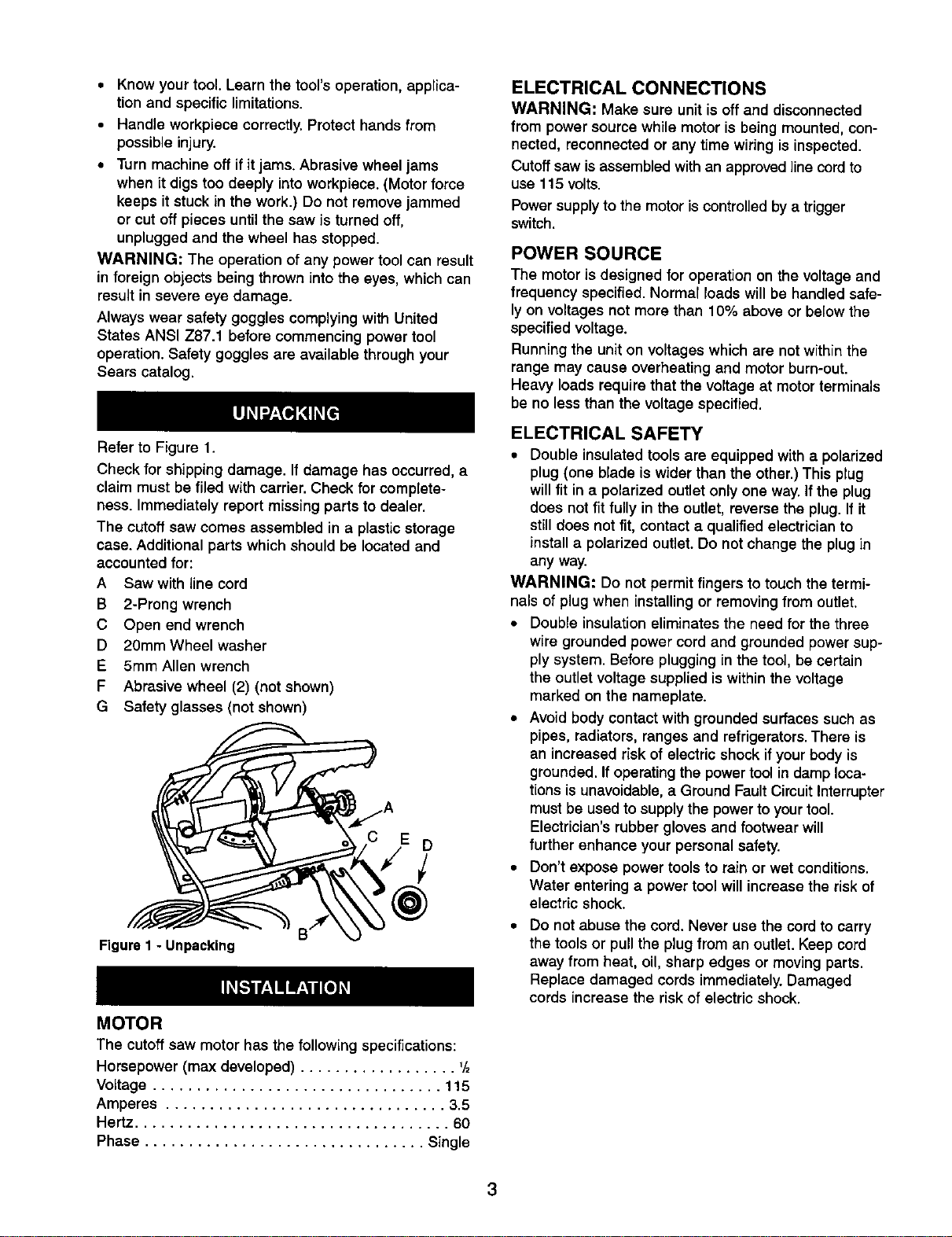
Refer to Figure 1.
Check for shipping damage. If damage has occurred, a
claim must be filed with carrier. Check for complete-
ness. Immediately report missing parts to dealer.
The cutoff saw comes assembled in a plastic storage
case. Additional parts which should be located and
accounted for:
A Saw with line cord
B 2-Prong wrench
C Open end wrench
D 20mm Wheel washer
E 5mm Allen wrench
F Abrasive wheel (2) (not shown)
G Safety glasses (not shown)
Figure I - Unpacking
MOTOR
The cutoffsaw motor has the followingspecifications:
Horsepower (max developed) .................. '/2
Voltage ................................. 115
Amperes ................................ 3.5
Hertz .................................... 60
Phase ................................ Single
ELECTRICAL CONNECTIONS
WARNING: Make sure unit is offand disconnected
from power sourcewhile motoris being mounted,con-
nected, reconnectedor any time wiring isinspected.
Cutoffsaw is assembledwith an approvedlinecordto
use 115 volts.
Powersupplyto the motoriscontrolledbya trigger
switch,
POWER SOURCE
The motoris designed for operation on the voltageand
frequency specified.Normar loads willbe handled safe-
lyon voltages not more than 10% above or belowthe
specified voltage.
Runningthe uniton voltages which are notwithinthe
range may cause overheating and motor burn-out.
Heavy loads require that the voltage at motorterminals
be no lessthan the voltagespecified.
ELECTRICAL SAFETY
• Double insulatedtools are equipped with a polarized
plug (one blade is wider than the other.) This plug
will fitin a polarized outlet onlyone way.If the plug
does notfit fullyin the outlet, reversethe plug.If it
stilldoes not fit, contact a qualified electrician to
install a polarized outlet.Do not change the plug in
any way.
WARNING: Do not permit fingers to touchthe termi-
nals of plugwhen installing or removing from outlet.
• Double insulationeliminates the need for the three
wire grounded power cordand grounded power sup-
ply system. Before plugging in the tool, be certain
the outlet voltage supplied is withinthe voltage
marked on the nameplate.
• Avoid body contactwith grounded surfaces such as
pipes, radiators, ranges and refrigerators.There is
an increased risk of electricshock ifyourbody is
grounded. If operatingthe powertoolin damp loca-
tionsis unavoidable, a Ground FaultCircuitInterrupter
must be used to supplythe power toyourtool.
Electrician'srubber gloves and footwear will
further enhance your personal safety.
• Don't expose powertoolsto rain or wet conditions.
Water enteringa powertool will increasethe risk of
electric shock.
Do not abuse the cord. Never use the cordto carry
the tools or pull the plug from an outlet. Keep cord
away from heat, oil, sharp edges or moving parts.
Replace damaged cords immediately. Damaged
cords increase the risk of electric shock.
3
EXTENSION CORDS
• The use of any extension cordwill cause some drop
in voltageand loss of power.
• Wires of the extension cord must be ofsufficientsize
to carry the current and maintain adequate voltage.
• Use the table to determine the minimum wire size
(A.W.G.) extension cord.
• If the extension cord is worn, cut, or damaged in any
way, replace it immediately.
EXTENSION CORD LENGTH
Wire Size A.W.G.
Up to 25 ft................................ 18
NOTE: Using extension cords over 25 ft. long is not
recommended.
Refer to Figures 2 and 3.
The 6" Cutoff saw is used for cutting hard and soft
metals. The cutoff saw features a lightweight frame of
plastic and aluminum construction and a stamped steel
base to ensure durability.
Vise jaws can turn 0-45° for making angle cuts. Movable
jaw has rapid approach and withdraw capability.
SPECIFICATIONS
Jaw opening ............................. 33/4"
Jaw height ............................... 13/8"
Abrasive wheel diameter ................. 150mm
Abrasive wheel inner diameter .............. 22mm
Abrasive wheel thickness ................... 2mm
Abrasive wheel speed (no load) ......... 7500 RPM
Overall dimensions ................ 6'/, x 133/,x 8"
Weight ................................ 12 Ibs
Capacity at 90°: ............. Round = 2" Diameter
Rectangular = 23/8x 1'/,"
Square = 1'/2"
Capacity at 45°: ............ Round = 1'/2"Diameter
Rectangular = 15/8x 1'/8"
Square = 1'/2"
SAFETY PRECAUTIONS
WARNING: Always observe the followingsafety pre-
cautions.
• Whenever adjustingor replacing any parts on the
cutoff saw, remove plug from powersource.
• Use a clean abrasive wheel. Replace chippedor
clogged wheels.
• Use abrasive wheels rated for saw speed
• Secure the workpieca in a stable position.
• Check that all guards are attached.
• Check t_at there isno debrison wheel or insideblade
guard.
• Keep hands away from the abrasive wheel and all
moving parts.
• Always wear eye protection or face shield.
CLAMPING WORKPIECE
Refer to Figure 3.
The vise is designed to keep the workpiece steady
while it is being cut. The proper position will help pro-
duce a safe and accurate cut.
• The entire length of long work should be supported.
Do not balance work on base. Use supports to
prevent the work from falling off after the cut.
• Vise jaw with protractor (Key No. 36) can be adjust-
ed from 0° to 45°. To change the angle of cut loosen
two socket head bolts (Key No. 45), adjust vise jaw
to desired angle and tighten socket head bolts.
• Raise lead nut (Key No. 39) off lead screw (Key No.
41). Pull lead screw out to open vise.
• Set workpiece between vise jaws. Push lead screw in
to clamp vise jaws onto workpiece. Lower lead nut to
engage lead screw. Tighten lead screw. Make sure
workpiece is securely clamped.
• Check workpiece position by lowering abrasive wheel.
CUTTING
• To cut, grip handle of housing,squeeze and main-
tain trigger. Let saw come to full speed, then press
down on handle to lower the abrasive wheel onto
workpiece.
• Do not force the tool during operation. Apply steady
but not heavy hand pressure. Heavy hand pressure
will reduce the life of the abrasive wheel.
• If the saw chatters or slows, reduce pressure. If
abrasivewheel stalls, release triggerto avoid burn-
ingout the motor.
• Note: When cutting large solid pieces (e.g. 2" dia.
round), do not overload motor-- use light to
moderate hand pressure.
• If feed pressure istoo low,the abrasive wheel will
not dig into material properly.
• Do not use to cut wood or plastic materials with
abrasive wheel. Do not use to cut flammable
materials.
• Do not use cuttingfluids. This tool uses the high
RPM of its abrasive wheel to cut through metal
workpieces.
• Do not block or cover vent slots in housing; free air
flow is needed to keep the motor cool.
4
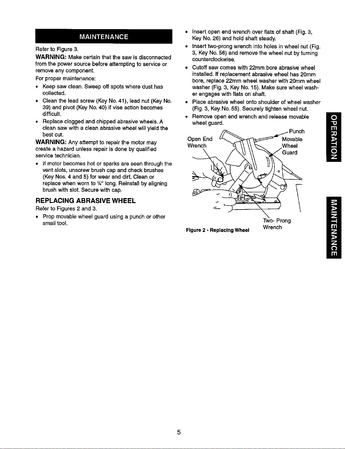
Refer to Figure 3.
WARNING: Make certain that the saw isdisconnected
from the powersource beforeattempting to service or
remove any component.
For proper maintenance:
• Keep saw clean. Sweep off spotswhere dust has
collected.
• Clean the lead screw (Key No. 41), lead nut (Key No.
39) and pivot (Key No. 40) if vise action becomes
difficult.
• Replace clogged and chippedabrasive wheels. A
clean saw with a clean abrasive wheel will yield the
best cut.
WARNING: Any attempt to repair the motor may
create a hazard unless repair is done by qualified
service technician.
If motor becomes hot or sparks are seen through the
vent slots, unscrew brush cap and check brushes
(Key Nos. 4 and 5) for wear and dirt. Clean or
replace when worn to '/," long. Reinstallby aligning
brush with slot. Secure with cap.
REPLACING ABRASIVE WHEEL
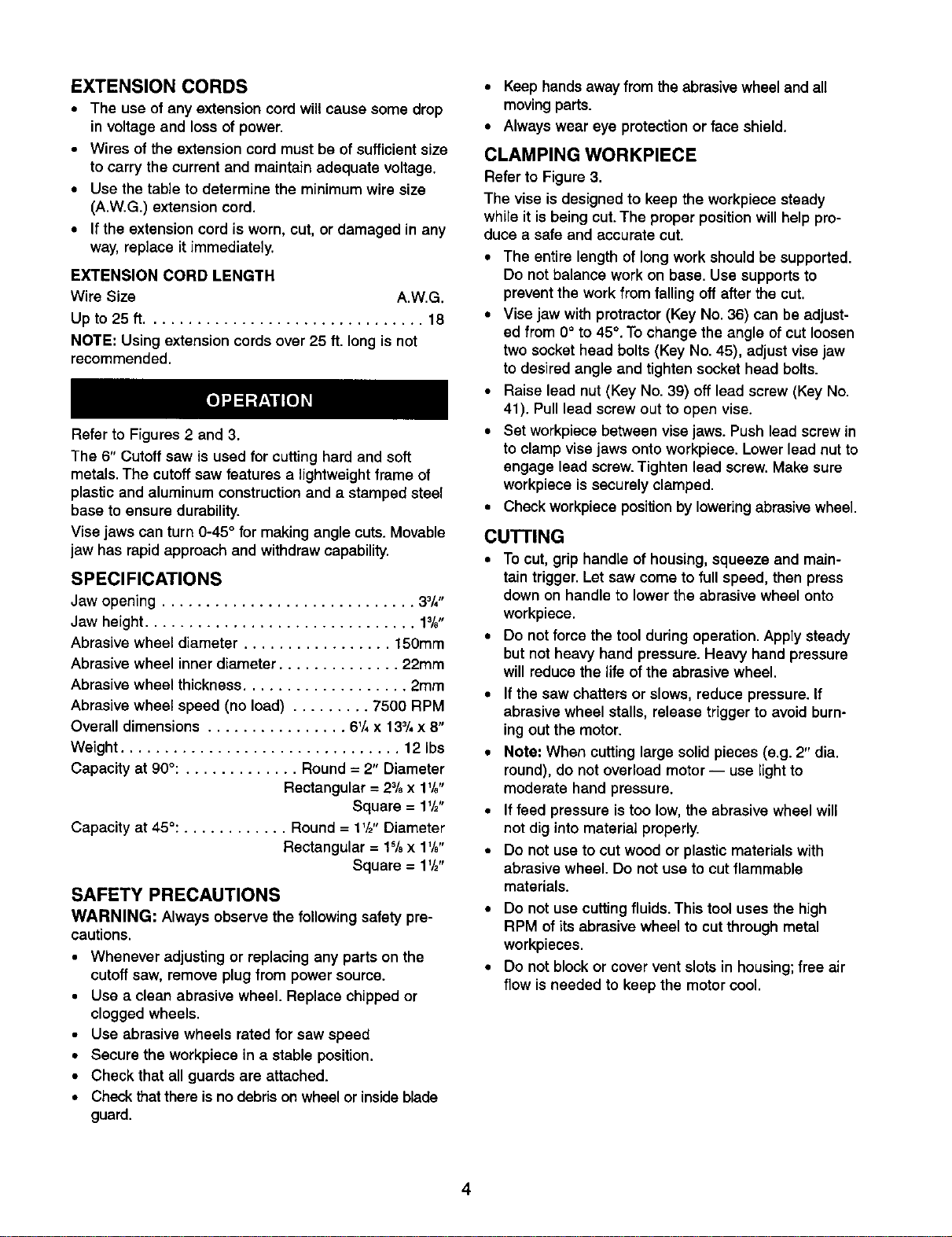
Refer to Figures 2 and 3.
• Prop movable wheel guard using a punch or other
small tool.
• Insert open end wrench over flats of shaft(Fig. 3,
Key No. 26) and hold shaft steady.
• Insert two-prong wrench into holes in wheel nut (Fig.
3, Key No. 56) and remove the wheel nut by turning
counterclockwise.
• Cutoff saw comes with 22ram bore abrasive wheel
installed. If replacement abrasive wheel has 20mm
bore, replace 22mm wheel washer with 20mm wheel
washer (Fig. 3, Key No. 15). Make sure wheel wash-
er engages with flats on shaft.
• Place abrasive wheel onto shoulder of wheel washer
(Fig. 3, Key No. 55). Securely tighten wheel nut.
• Remove open end wrench and release movable
wheel guard.
Open End Movable
Wrench
Figure 2 - Replacing Wheel
Two- Prong
Wrench
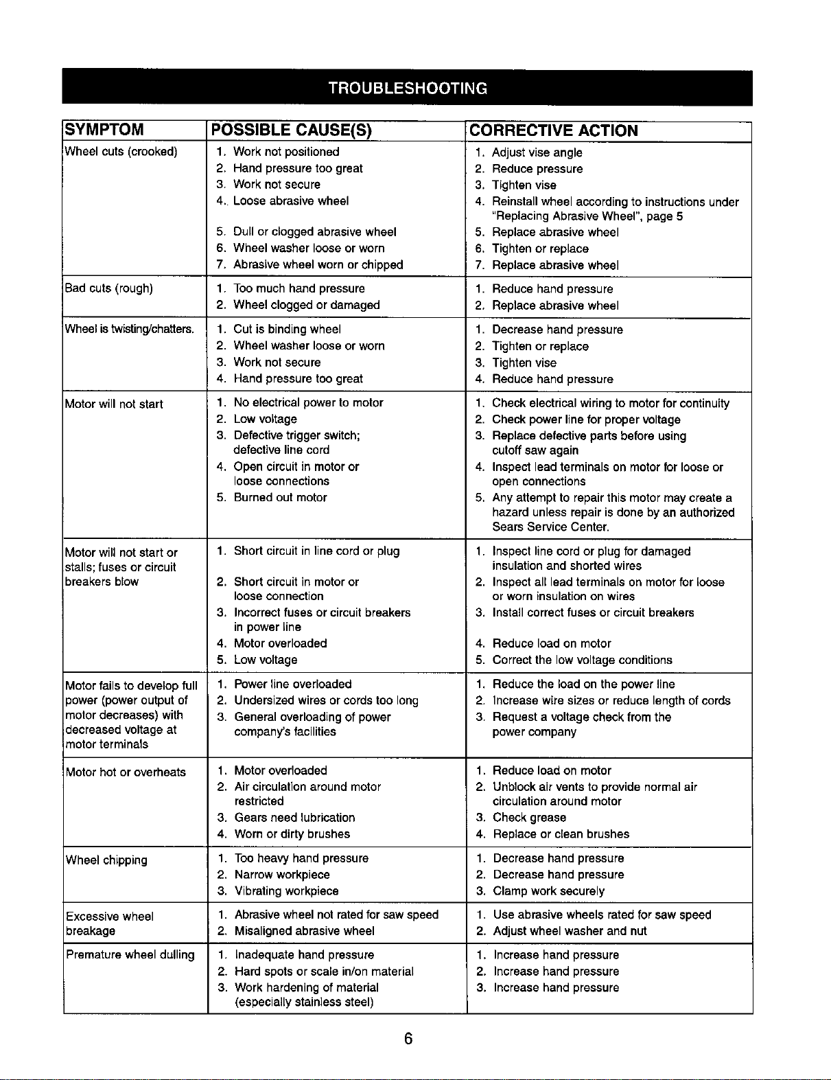
SYMPTOM POSSIBLE CAUSE(S)
Wheel cuts (crooked) 1. Work not positioned
2. Hand pressure too great
3. Work not secure
4. Loose abrasive wheel
5. Dull or clogged abrasive wheel
6. Wheel washer loose or worn
7. Abrasive wheel worn or chipped
CORRECTIVE ACTION
1. Adjustvise angle
2. Reduce pressure
3. Tighten vise
4. Reinstall wheel according to instructionsunder
"Replacing Abrasive Wheel", page 5
5. Replace abrasive wheel
6. Tighten or replace
7. Replace abrasive wheel
Bad cuts (rough) 1. Too much hand pressure 1. Reduce hand pressure
2. Wheel clogged or damaged 2. Replace abrasive wheel
Wheel is twisting/chatters. 1. Cut is binding wheel 1. Decrease hand pressure
2. Wheel washer loose or worn 2. Tighten or replace
3. Work not secure 3. Tighten vise
4. Hand pressure too great 4. Reduce hand pressure
Motor will not start
1, No electrical powerto motor
2. Low voltage
3. Defective trigger switch;
defective line cord
4. Open circuit in motor or
loose connections
5. Burned out motor
1. Short circuit in line cord or plug
2. Short circuit in motor or
loose connection
3. Incorrect fuses or circuit breakers
in power line
4. Motor overloaded
5. Low voltage
Motor will not start or
stalls; fuses or circuit
breakers blow
1. Check electrical wiringto motorfor continuity
2. Check power line for proper voltage
3. Replace defective parts before using
cutoff saw again
4. Inspect lead terminals on motor for loose or
open connections
5, Any attempt to repair this motor may create a
hazard unless repair is done by an authorized
Sears Service Center.
1. Inspect line cord or plug for damaged
insulationand shorted wires
2. Inspect all lead terminals on motor for loose
or worn insulation on wires
3. Install correct fuses or circuit breakers
4. Reduce load on motor
5. Correct the low voltage conditions
Motor fails to develop full 1. Power line overloaded 1. Reduce the load on the power line
power (power output of 2. Undersized wires or cords too long 2. Increase wire sizes or reduce length of cords
motor decreases) with 3. General overloading of power 3. Request a voltage check from the
"_ecreased voltage at company's facilities power company
imotor terminals
'vlotor hot or overheats 1. Motor overloaded 1. Reduce load on motor
2. Air circulation around motor 2. Unblock air vents to provide normal air
restricted circulationaround motor
3. Gears need lubrication 3. Check grease
4. Worn or dirty brushes 4. Replace or clean brushes
C/heel chipping 1. Too heavy hand pressure 1. Decrease hand pressure
2. Narrow workpieee 2. Decrease hand pressure
3. Vibrating workpiece 3. Clamp work securely
Excessive wheel 1. Abrasive wheel not rated for saw speed 1. Use abrasive wheels rated for saw speed
oreakage 2, Misaligned abrasive wheel 2. Adjust wheel washer and nut
Premature wheel dulling 1. Inadequate hand pressure 1. Increase hand pressure
2. Hard spots or scale in/on material 2. Increase hand pressure
3. Work hardening of material 3. Increase hand pressure
(especially stainless steel)
6
Service Record
Craftsman 6" Cutoff Saw
DATE MAINTENANCE PERFORMED REPLACEMENT PARTS REQUIRED ]
7
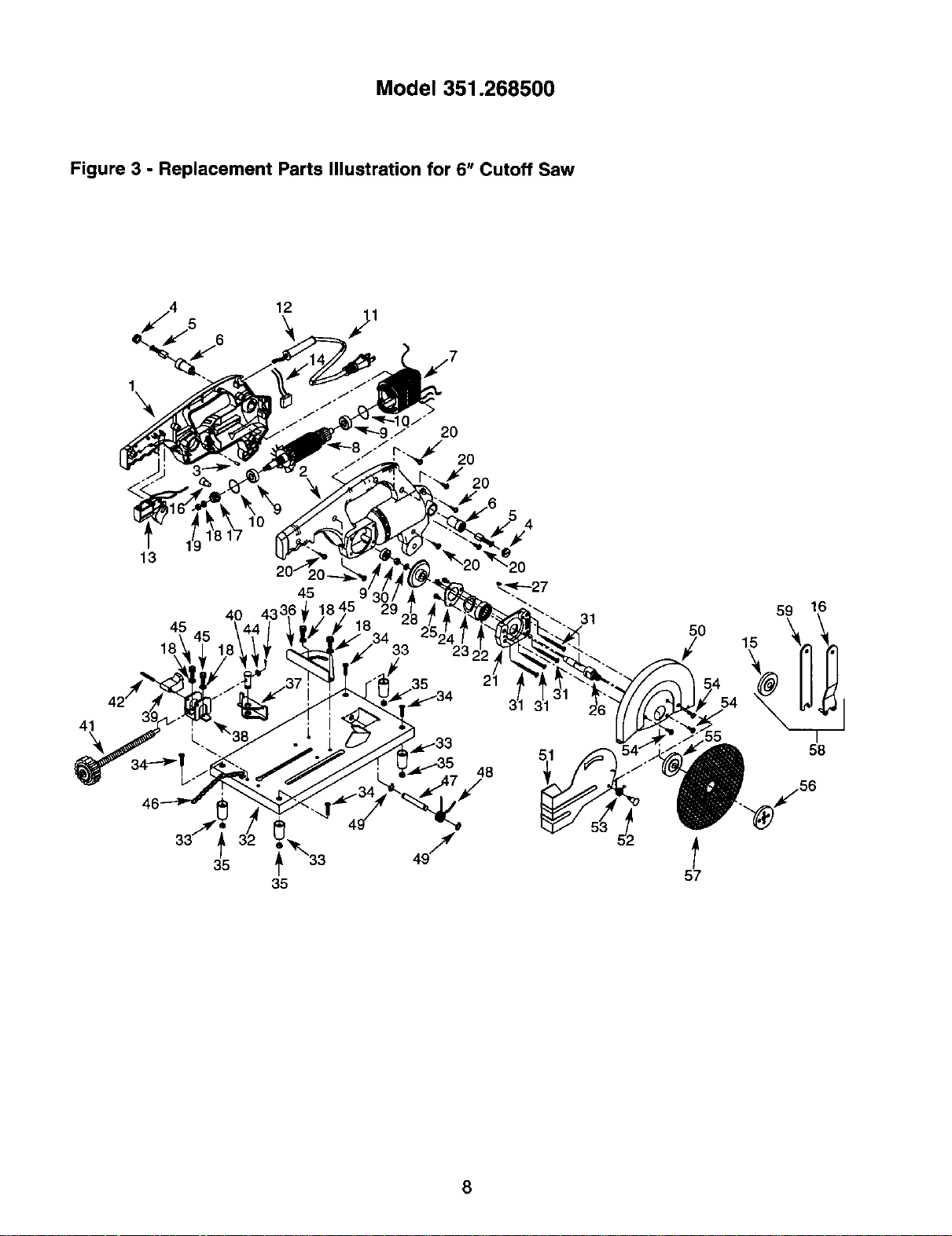
Model351.268500
Figure 3 - Replacement Parts Illustration for 6" Cutoff Saw
12
4_
13
40
45
35
45
35
4
48
31
5O
59 16
r
58
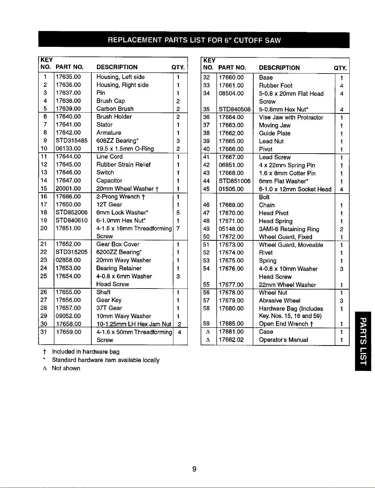
KEY
NO. PART NO.
1 17635.00
2 17636.00
3 17637.00
4 17638.00
5 17639.00
6 17640.00
7 17641.00
8 17642.00
9 STD315485
10 06133.00
11 17644.00
12 17645.00
13 17646.00
14 17647.00
15 20001.00
16 17686.00
17 17650.00
18 STD852006
19 STD840610
20 17661.00
21 17652.00
22 STD315205
23 02858.00
24 17653.00
25 17654.00
26 17655.00
27 17656.00
28 17657.00
29 09052.00
30 17658.00
31 17659.00
DESCRIPTION QTY.
Housing, Left side 1
Housing, Right side 1
Pin 1
Brush Cap 2
Carbon Brush 2
Brush Holder 2
Stator 1
Armature 1
608ZZ Bearing* 3
19.5 x 1.5mm O-Ring 2
Line Cord 1
Rubber Strain Relief 1
Switch 1
Capacitor 1
20mm Wheel Washer 1- 1
2-Prong Wrench t 1
12T Gear 1
6mm Lock Washer* 5
6-1.0mm Hex Nut* 1
4-1.6 x 16mmThreadforming 7
1
1
1
1
3
Screw
Gear Box Cover
6200ZZ Bearing*
20mm Wavy Washer
Bearing Retainer
4-0.8 x 6mm Washer
Head Screw
Shaft 1
Gear Key 1
37T Gear 1
10mm Wavy Washer 1
10-1.25mm LH Hex Jam Nut 2
4-1.6 x 50mm Threadforming 4
Screw
t Included in hardware bag
Standard hardware item available locally
A Not shown
KEY
NO. PART NO,
32 17660.00
33 17661.00
34 08504.00
35 STD840508
36 17664.00
37 17663.00
38 17662.00
39 17665.00
40 17666.00
41 17667.00
42 06851.00
43 17668.00
44 STD851006
45 01505.00
46 17669.00
47 17670.00
48 17671.00
49 05148.00
50 17672.00
51 17673.00
52 17674.00
53 17675.00
54 17676.00
56 17677.00 1
56 17678.00 1
57 17679.00 3
58 17680.00 1
59 17685.00 1
A 17681.00 1
17682.02 1
DESCRIPTION QTY.
Base 1
Rubber Foot 4
5-0.8 x 20mm Flat Head 4
Screw
5-0.8mm Hex Nut* 4
Vise Jaw with Protractor 1
Moving Jaw 1
Guide Plate 1
Lead Nut 1
Pivot 1
Lead Screw 1
4 x 22mm Spring Pin 1
1.6 x 8mm Cotter Pin 1
6mm Flat Washer* 1
6-1.0 x 12mm Socket Head 4
Bolt
Chain 1
Head Pivot 1
Head Spring 1
3AMI-8 Retaining Ring 2
Wheel Guard, Fixed 1
Wheel Guard, Moveable 1
Rivet 1
Spring 1
4*0.8 x 10mm Washer 3
Head Screw
22mm Wheel Washer
Wheel Nut
Abrasive Wheel
Hardware Bag (Includes
Key.Nos. 15, 16 and 59)
Open End Wrench t
Case
Operator's Manual
9
i!_I !i!i_
Your Home
For repair-in your home-of all major brand appliances,
lawn and garden equipment, or heating and cooling systems,
no matter who made it, no matter who sold it!
For the replacement parts, accessories and
owner's manuals that you need to do-it-yourself.
For Sears professional installation of home appliances
and items like garage door openers and water heaters.
1-800-4-MY-HOME ® (1-800-469-4663)
Call anytime, day or night (U.S.A. and Canada)
i;i_iiiiii
www.sears.com www.sears.ca
........ Our Home
For repair of carry in items like vacuums lawn equipment
!i!!_i
and electronics, call or go on-line for the location of your nearest .....:
Sears Parts & Repair Center.
1 800 488 1222 .....i i i
..... Call anytime day or night (U S A only)
.... www sears com .....
To purchase a protection agreement on a product serviced by Sears:
12
; i i
.... 1-800-827-6655 (U.S.A.) 1-800-361-6665 (Canada)
,i i_iI_
Para pedir servicio de reparaci6n
a domicilio, y para ordenar piezas:
1-888-SU-HOGAR _
(1-888-784-6427)
Au Canada pour service en fran£ais:
1-800-LE-FOYER "c
(1-800-533-6937)
www.sears.ca
® Registered Trademark / TM Trademark/ SMServiceMark ofSears, Roebuckand Co.
® Marca Registrada/ TMMama de F&brica/ SMMarcade Serviciode Sears, Roebuckand Co.
MCMarquede commerce/ MoMarqueddpos_ede Sears, Roebuck andCo. © Sears, Roebuckand Co.