EN
PKIW1UMEN-003
www.bora.com
1041652
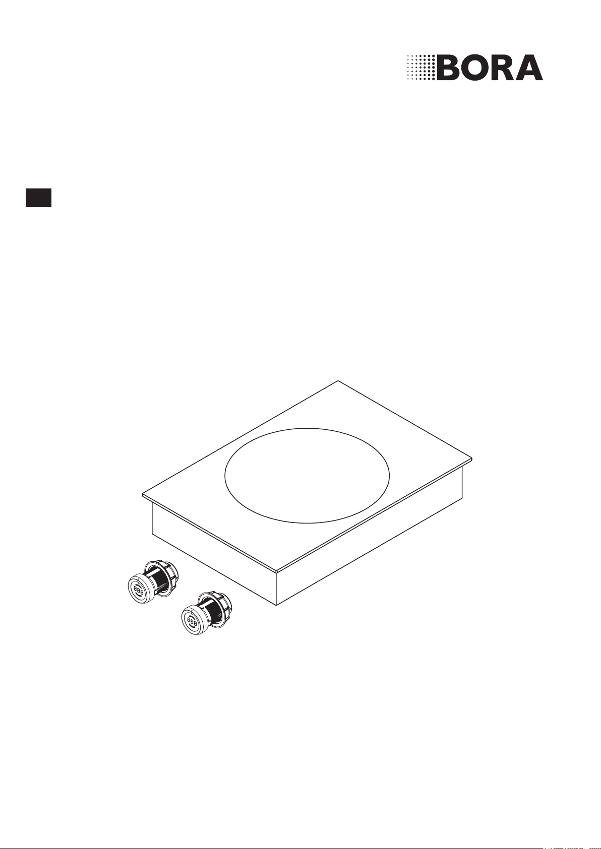
Operating and installation instructions PKIW1
BORA Pro Induction glass ceramic wok

Operating and installation instructions: Original Translation
Manufacturer
BORA Vertriebs GmbH & Co KG
Innstraße 1
6342 Niederndorf
Austria
Contact
T +43 (0) 5373 / 62250-0
www.bora.com
The distribution and duplication of this document, as well as the use and disclosure of its contents are prohibited
unless expressly authorised.
These operating and installation instructions have been drawn up with the greatest of care. But it cannot be ruled
out that subsequent technical modifications have not yet been incorporated or the relevant content has not yet been
adapted. Please accept our apologies in this eventuality. An updated version can be requested from the BORA Service
Team. Subject to printing errors and mistakes.
© BORA Vertriebs GmbH & Co KG
All rights reserved.

EN
3
www.bora.com
Table of Contents
1 General information 4
1.1 Target group ........................................................ 4
1.2 Validity of the operating and installation
instructions ......................................................... 4
1.3 Other applicable documents ............................... 4
1.4 Presentation of information ................................. 5
2 Safety 6
2.1 General safety instructions ................................. 6
2.2 Safety instructions – operation ........................... 7
2.3 Safety instructions – installation ......................... 9
2.4 Safety instructions – disassembly
and disposal ........................................................ 9
2.5 Safety instructions – spare parts ......................10
2.6 Intended use ..................................................... 10
3 Technical data 11
4 Device description 12
4.1 Structure ........................................................... 12
4.2 Operating principle ............................................12
4.3 Functional principle ........................................... 13
4.3.1 Power levels ...................................................... 13
4.3.2 Power setting .................................................... 13
4.3.3 Automatic heat up function ...............................13
4.3.4 Heat retention levels ......................................... 14
4.3.5 Suitable cookware .............................................14
4.3.6 Pan size recognition ..........................................14
4.3.7 Timer functions ................................................. 14
4.3.8 Pause function .................................................. 15
4.4 Safety devices ................................................... 15
4.4.1 Residual heat display.........................................15
4.4.2 Safety shut-down .............................................. 15
4.4.3 Overheating protection ......................................15
4.4.4 Childproofing feature .........................................15
5 Installation 16
5.1 Checking the scope of delivery .........................16
5.2 Tool and aids ..................................................... 16
5.3 Assembly instructions .......................................16
5.3.1 Safety clearances .............................................. 16
5.3.2 Work surface and kitchen units .........................16
5.3.3 Cooktop air intake ............................................. 17
5.4 Cut-out dimensions ...........................................17
5.4.1 Flush installation ............................................... 17
5.4.2 Surface mounting .............................................. 18
5.5 Installing the cooktop ........................................18
5.5.1 Removing the plastic strip from
the side of the cooktop extractor ......................18
5.5.2 Installing the control knob behind
the floor unit’s panel .........................................19
5.5.3 Installing the cooktop ........................................20
5.5.4 Sealing the cooktop ..........................................21
5.5.5 Establishing communications ............................ 21
5.5.6 Establishing the power connection....................22
5.6 Configuration menu ..........................................22
5.6.1 Opening the configuration menu ....................... 22
5.6.2 Selecting a menu item ......................................23
5.6.3 Changing the set value ......................................23
5.6.4 Exiting the configuration menu..........................23
5.7 Handover to user ............................................... 23
6 Operation 24
6.1 General operating instructions .......................... 24
6.2 Operating the cooktop ......................................24
6.2.1 Switching on the cooking zone .........................24
6.2.2 Power setting ................................................... 24
6.2.3 Automatic heat up function ...............................24
6.2.4 Heat retention level ........................................... 25
6.2.5 Childproofing feature .........................................25
6.2.6 Using the timer function ....................................26
6.2.7 Pause function .................................................. 26
6.2.8 Switching off the cooking zone .........................26
6.3 Configuration menu ...........................................27
7 Cleaning and maintenance 28
7.1 Cleaning agents ................................................. 28
7.2 Looking after the cooktop ................................. 28
7.3 Cleaning the cooktop ........................................28
7.4 Cleaning the control knobs ...............................29
7.4.1 Cleaning the knob ring ......................................29
7.4.2 Cleaning the touch surface and
the knob housing ............................................... 29
8 Troubleshooting 30
9 Decommissioning, disassembly
and disposal 31
9.1 Decommissioning .............................................. 31
9.2 Disassembly ...................................................... 31
9.3 Environmentally-friendly disposal ...................... 31
10 Warranty, technical service,
spare parts, accessories 32
10.1 Warranty ............................................................ 32
10.2 Service .............................................................. 32
10.3 Replacement parts ............................................32
10.4 Accessories ....................................................... 32
11 Notes 33
EN
4
General information
www.bora.com
1 General information
1.1 Target group
These operating and installation instructions apply for the
following target groups:
Target group Requirements
User The appliance can be used by children
aged 8 and above as well as people with
reduced physical, sensory or mental
capacities or a lack of experience and/or
knowledge if they are supervised or have
been instructed how to safely use the
appliance and understand the resultant
risks. Children must be supervised. All
safety and warning information and the
handling instructions in the installation
instructions must be complied with.
Ambitious DIYers Ambitious DIYers can independently
conduct all joinery and installation work
providing they possess the necessary
skills and expertise. They must never
independently establish electricity and
gas connections.
Installation specialists Installation specialists are authorised
to conduct all joinery and installation
work in line with
existing regulations. The
electricity and gas connections must be
certified by a certified engineer for the
applicable trade prior to commissioning.
Electricians The electrical connection may only be
established by a certified engineer.
He/she also assumes responsibility for
the proper electrical installation and
commissioning.
Gas specialists The gas connection may only be
established by certified engineers.
They also assume responsibility for
proper installation and commissioning of
the gas system.
Tab. 1.1 Target groups
INFO BORA Holding GmbH, BORA Vertriebs GmbH
& Co KG, BORA APAC Pty Ltd and BORA
Lüftungstechnik GmbH - hereinafter referred
to as BORA - do not assume any liability for
damage arising from non-adherence to these
documents and from improper assembly! The
electricity and gas connections must be made
by a qualified specialist. Installation must
comply with the valid standards, regulations
and laws. All safety and warning information
and the operating and installation instructions
must be complied with.
1.2 Validity of the operating and
installation instructions
These instructions apply to several device versions. It is
therefore possible that some of the features described do
not apply to your appliance.
1.3 Other applicable documents
These operating and installation instructions are valid
in conjunction with other documents, which must be
adhered to.
Please be sure to adhere to all documents that form part
of the scope of delivery.
INFO BORA accepts no liability for damage caused
by failure to comply with these documents!
Directives
This device meets the following EU/EC directives:
2014/30/EU EMC Directive
2014/35/EU Low Voltage Directive
2009/125/EC Ecodesign Directive
2011/65/EU RoHS Directive
2012/19/EU WEEE Directive
EN
5
General information
www.bora.com
1.4 Presentation of information
To make working with these instructions quick and
easy, consistent formatting, numbering, symbols,
safety instructions, terms and abbreviations are used
throughout.
Handling instructions are market with an arrow.
Always carry out handling instructions in the sequence
shown.
Bullet points are indicated by a square bullet point at
the edge of the line.
Bullet point 1
Bullet point 2
INFO Information points out specific points you must
always comply with.
Safety and warning information
The safety and warning information in these instructions
are highlighted with symbols and signal words.
Safety and warning information is structured as follows:
WARNING SYMBOL AND SIGNAL
WORD!
Type and source of the danger
Consequences of non-compliance
Measures to minimise risk
The following applies:
The warning symbol draws attention to the danger.
The signal word indicates the severity of the risk.
Warning sign Signal word Hazard
Danger Indicates an imminent hazardous
situation which could lead to
death or serious injury
if ignored.
Warning Indicates an imminent hazardous
situation which could lead to
death or serious injury if
ignored.
Caution Indicates a potentially hazardous
situation which could lead to slight
or minor injuries if ignored.
— Caution Indicates a situation which could
result in material damage if
ignored.
Tab. 1.2 Meaning of warning symbols and signal words

EN
6
Safety
www.bora.com
2 Safety
2.1 General safety instructions
INFO The appliance complies with the
stipulated safety requirements. The
user is responsible for appliance
cleaning and maintenance as well as
its safe use. Improper use can lead
to personal injury and damage to
property.
The operating and installation instructions
contain important information about
installation and operation. These enable you
to protect yourself against injuries and
prevent damage to the appliance. Contact
details for further information as well as
application and usage questions can be
found on the back of these operating and
installation instructions.
The term device applies to cooktops,
cooktop extractors and cooktops with
cooktops extractors.
Read the operating and installation
instructions fully before using the appliance
for the first time.
Always store the operating and installation
instructions within easy reach so that they
can be accessed if required.
Pass the operating and installation
instructions to the next owner if you sell
the appliance.
Conduct all work extremely attentively and
conscientiously.
Check the appliance for visible damage
when unpacking it.
Do not connect a damaged appliance.
Only use the appliance once all installation
activities are complete. This is the only way
to ensure safe operation.
Make sure that hot hobs are not touched.
Avoid boiling over.
Pay attention to the residual heat display.
Switch the device off after use.
Do not rely on the pan size recognition.
Keep pets away from the appliance.
CAUTION!
Risk of injury from falling device
components!
Falling device components such
as pan supports, control elements,
covers,greaselters,etc.cancause
injuries.
Place device components safely
near the devices after you remove
them.
Make sure that none of the device
components you have removed
could fall.
Recirculation mode
INFO When cooking, additional moisture is
released into the ambient air.
INFO In recirculation mode, only a slight
amount of moisture is removed from
the cooking vapour.
When using recirculation mode, ensure a
sufficient supply of fresh air, e.g. by
opening a window.
Ensure a normal and comfortable room
climate (humidity of 45–60%), e.g. by
opening natural ventilation openings or
using domestic ventilation systems.
After every use in recirculation mode,
switch the cooktop extractor to a low level
for about 20 minutes or activate the
automatic after-run function.
Effect on pacemakers, hearing aids and
metallic implants
INFO Induction cooktops generate a high-
frequency electromagnetic field near
the cooking zones. Coming too close
to the cooking zones could have a
negative influence or even cause
malfunctions of pacemakers, hearing
aids or metallic implants. Issues with
pacemakers are unlikely.
In case of doubt, please contact the
manufacturer of your medical device or
your doctor.
EN
7
Safety
www.bora.com
Make sure the base of the cookware and
the cooking zone are clean and dry.
Always lift the cookware (do not pull) to
avoid scratching or wearing the surface.
2.2 Safety instructions – operation
Cooktop
DANGER!
Unsupervised cooktops are a fire
risk!
Oilandfatcanheatupandcatchre
quickly.
Never leave hot oil or fat
unattended.
Never attempt to extinguish
burning oil or fat with water.
Stifle the fire using a lid, for
example.
DANGER!
Risk of explosion caused by
flammable liquids!
Flammable liquids in the vicinity of
the cooktop can explode and cause
serious injury.
Do not place any flammable liquids
in the vicinity of the cooktop.
DANGER!
Risk of electric shock!
Chips, cracks or breaks in the glass
ceramic panel can expose or damage
the electronics underneath. This can
lead to an electric shock.
If the glass ceramic panel gets
chipped, broken or cracked, switch
the cooktop off immediately.
Securely disconnect the appliance
from the mains using LS switches,
fuses, automatic circuit breakers
or contactors.
Households with children and people with
special needs
The appliance can be used by children aged
8 and above as well as people with reduced
physical, sensory or mental capacities or a
lack of experience and/or knowledge if
they are supervised or have been instructed
how to safely use the appliance and
understand the resultant risks.
Supervise children in the vicinity of the
appliance.
Children must not play with the appliance.
Use the childproofing feature to prevent
children accidentally switching the cooktop
on or changing the settings.
Do not store any items that could be of
interest to children in storage spaces above
or behind the appliance. Children will
otherwise be encourage to climb on the
appliance.
Keep children and other people away from
hot hobs.
Unauthorised modifications
Unauthorised modifications can cause the
appliance to pose risks.
Do not conduct any modifications to the
appliance.
Cleaning and maintenance
The device must be cleaned regularly. Dirt
can lead to damage or the buildup of odours.
Remove any dirt immediately.
Cleaning and maintenance work must not
be carried out by children unless they are
supervised at all times.
Do not use steam cleaners. The steam can
cause a short-circuit on live parts and
cause damage to property (see Cleaning
and maintenance section).
Make sure no water penetrates inside the
device when cleaning. Only use a slightly
damp cloth. Never spray water on the
device. Water ingress can cause damage!
Where possible, clean the cooktop after
every cooking session.
Only clean the cooktop when it has cooled
down.
For cleaning, only use non-abrasive
detergents to avoid scratching or wearing
the surface.
EN
8
Safety
www.bora.com
WARNING!
Risk of getting burnt!
Liquid between the cooking zone
and the pan base can evaporate and
cause burns.
Make sure that the cooking zone
and the pan base are always dry.
CAUTION!
Damage from hard and pointed
objects!
Hard and pointed objects can
damage the glass ceramic panel of
the cooktop!
Do not use the surface of the
cooktop as a worktop.
Do not use hard and pointed
objects when working on the
cooktop.
CAUTION!
Damage from sugary and salty
foods!
Sugary and salty foods and juices
can damage the hot cooking zone.
Make sure sugary and salty foods
or juices do not get onto the
cooking zone while it is hot.
Remove sugary and salty foods
and juices from the hot cooking
zone.
CAUTION!
Escaping hot liquids!
Unattended pans can boil over
allowing hot liquids to escape.
Always keep an eye on pans while
cooking.
Short cooking sessions must be
constantly monitored.
CAUTION!
Damage from objects on the
cooktop!
Objects such as pan lids on the
cooktop can damage the glass
ceramics.
Do not leave objects on the hot
cooktop.
WARNING!
Risk of burns from hot cooktop!
The cooktop and its exposed areas
get hot during use. Once the cooking
zoneisswitchedo,ittakesalittle
while to cool down below 60 °C.
Touching hot surfaces can cause
serious burns.
Never touch the cooktop when it
is hot.
Keep children away from the
cooktop when it is hot or ensure
they are supervised at all times.
WARNING!
Leaving items on the cooking
surface is a fire risk!
The cooktop and its touchable parts
are hot when the cooking zone is
switched on and during the cooling
phase. Objects on the cooktop can
gethotandcatchre.
Do not place any items on the
cooktop.
WARNING!
Risk of burns from hot items!
The cooktop and its touchable parts
are hot during both operation and the
cooling phase. Items placed on the
cooktop heat up very quickly and can
cause severe burns. This particularly
applies to metal items (e.g. knives,
forks, spoons, lids or cooktop
extractor covers).
Do not place any items on the
cooktop.
Please use suitable tools (pot
holders, oven gloves).
WARNING!
Risk of burns from hot cookware!
Handles projecting over the edge are
enticing for children to grab.
Do not turn pot and pan handles
so they stick out beyond the work
surface.
Make sure that children cannot
pull hot pots and pans over.
A special stove guard for children
(available from specialist suppliers)
reduces the risk.
EN
9
Safety
www.bora.com
2.3 Safety instructions – installation
The device must only be installed and
assembled by trained specialists who are
familiar with and comply with the standard
national regulations and supplementary
regulations of the local utility companies.
Work on electrical components must be
conducted by trained electrical personnel.
The electrical safety of the appliance is only
guaranteed if it is connected to a protective
conductor system that has been installed in
line with regulations. Ensure that this basic
safety precaution is met.
Cooktop
DANGER!
Risk of electric shock!
Incorrect connection of the device
to the mains voltage could cause
electric shocks.
Make sure that the device is firmly
connected to the mains voltage.
Make sure the device is connected
to a properly installed earth
conductor system.
Make sure a system is installed
which allows disconnection from
the network with a contact
opening width of at least 3 mm
across all poles (circuit breaker,
fuses, automatic circuit breakers,
contactors).
DANGER!
Risk of electric shock!
If the mains connection cable comes
into contact with hot hobs, it could
get damaged. A damaged mains
connection cable can cause a
(deadly) electric shock.
Make sure that the mains
connection cable cannot come
into contact with hot hobs.
Make sure that the connection
cable is not squashed or damaged.
CAUTION!
Lifting heavy loads can cause back
injuries!
If not correctly handled, removing
and installing the device can causes
injuries to the limbs or torso.
Removing the cooktop from the
packaging is a two-person job.
Placing the cooktop into the
worktop cut-out is a two-person
job.
Use appropriate aids to prevent
damage or injuries to limbs or
torso.
Check the appliance for visible damage
before installing it.
Do not install damaged devices.
A damaged device is a hazard.
Repair work must only be carried out by
specialists authorised by the manufacturer.
2.4 Safety instructions –
disassembly and disposal
The device must only be disassembled by
trained specialists who are familiar with and
comply with the standard national regulations
and supplementary regulations of the local
utility companies.
Work on electrical components must only be
conducted by trained electrical personnel.
DANGER!
Risk of electric shock!
Incorrectly disconnecting the
appliance from the mains results in a
risk of electric shock.
Securely disconnect the appliance
from the mains using LS switches,
fuses, automatic circuit breakers
or contactors.
Use an authorised measuring
device to ensure that there is no
power to the appliance.
EN
10
Safety
www.bora.com
DANGER!
Risk of asphyxiation!
Packagingcomponents(e.g.lm,
polystyrene) can be life-threatening
for children.
Store all packaging components
out of reach of children.
Dispose of the packaging properly
and immediately.
2.5 Safety instructions – spare parts
WARNING!
Risk of injury and damage to
property!
Incorrect components can lead to
personal injury or damage to the
appliance.Modications,additionsor
alterations to the appliance can lead
to safety risks.
Only use original spare parts for
repairs.
2.6 Intended use
The device cannot be used at altitudes above
2000 m (metres above sea level).
The device is designed exclusively for the
preparation of food in private households.
This appliance is not intended for:
Outdoor use
Installation in vehicles
Heating rooms
Use in non-stationary installation sites
(e.g. on ships)
Use with an external timer or a separate
remote control system (remote operation)
Any use other than that specified in these
operating and installation instructions or any
use that goes beyond that which is described
here is classed as unintended. BORA does not
assume any liability for damages caused by
improper use or incorrect operation.
All misuse is prohibited!
INFO BORA Holding GmbH, BORA Vertriebs
GmbH & Co KG, BORA APAC Pty Ltd
and BORA Lüftungstechnik GmbH do
not assume any liability for damage
arising from non-adherence
to the
safety and warning information.
EN
11
Technical data
www.bora.com
3 Technical data
Parameter Value
Supply voltage 220 - 240 V
Frequency 50/60 Hz
Power consumption 3.0 kW
Fuse protection 1 x 16 A
Dimensions (width x depth x height) 370 x 540 x 128 mm
Weight (incl. accessories/packaging) 9.5 kg
Cooktop
Power levels 1 - 9, P
Heat retention levels 3
Cooking zone power setting Ø 310 mm 2400 W
3000 W
Tab. 3.1 Technical data
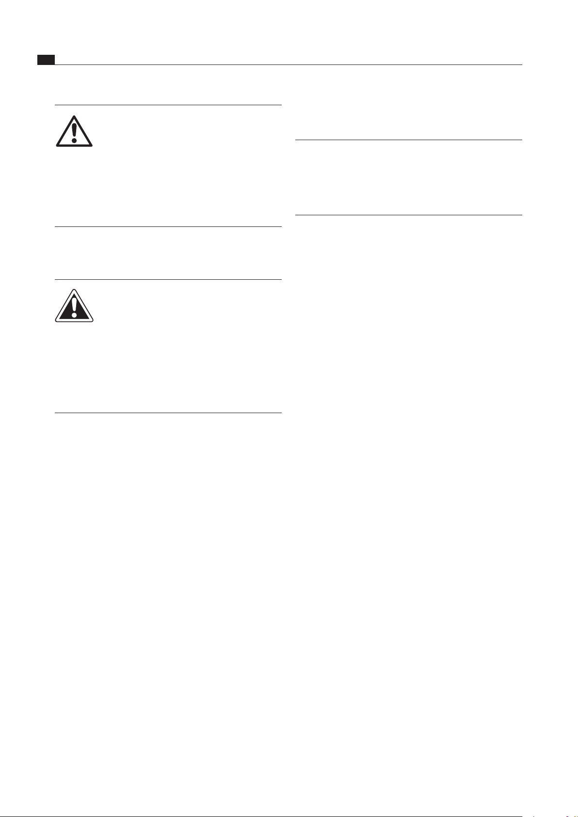
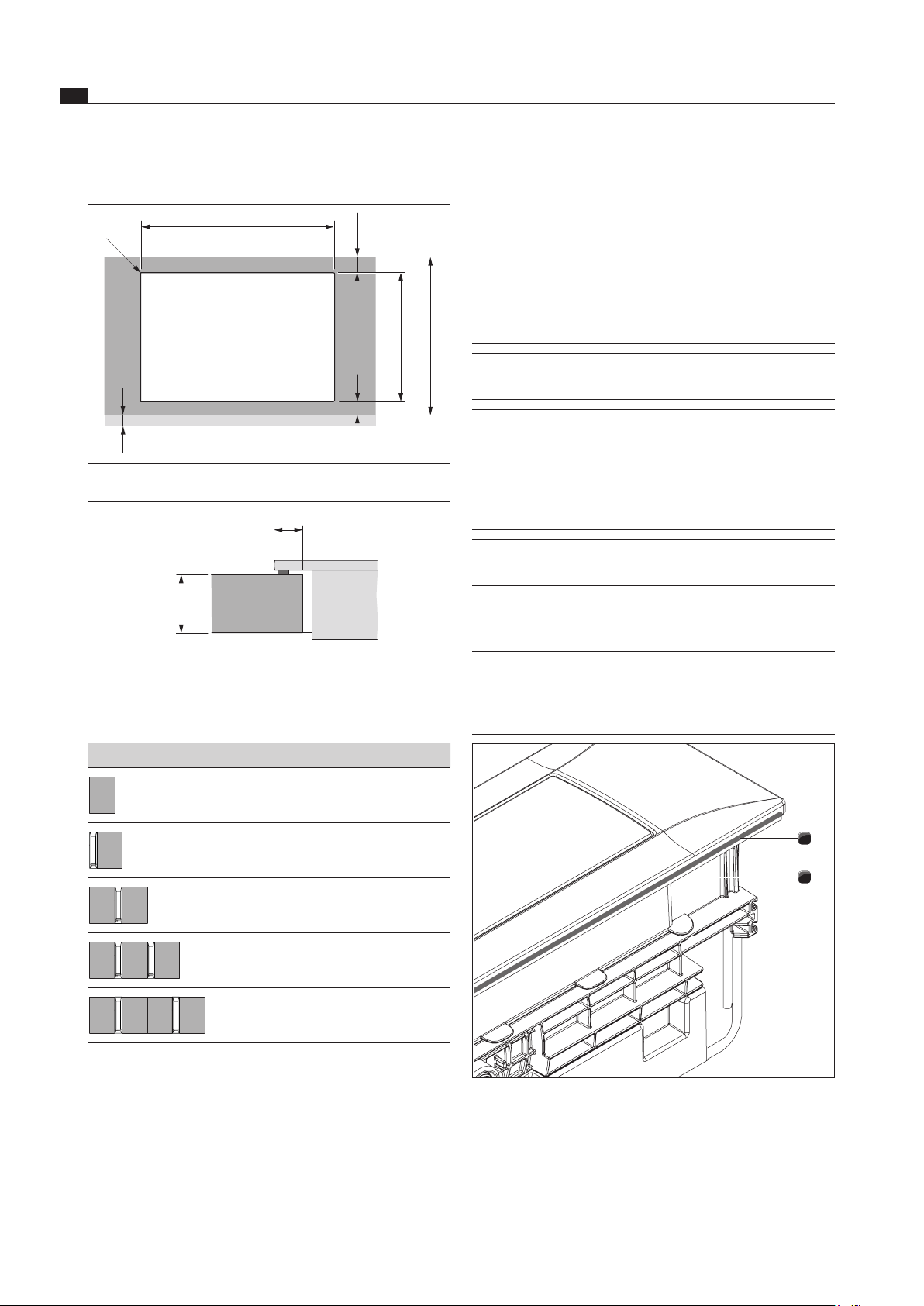
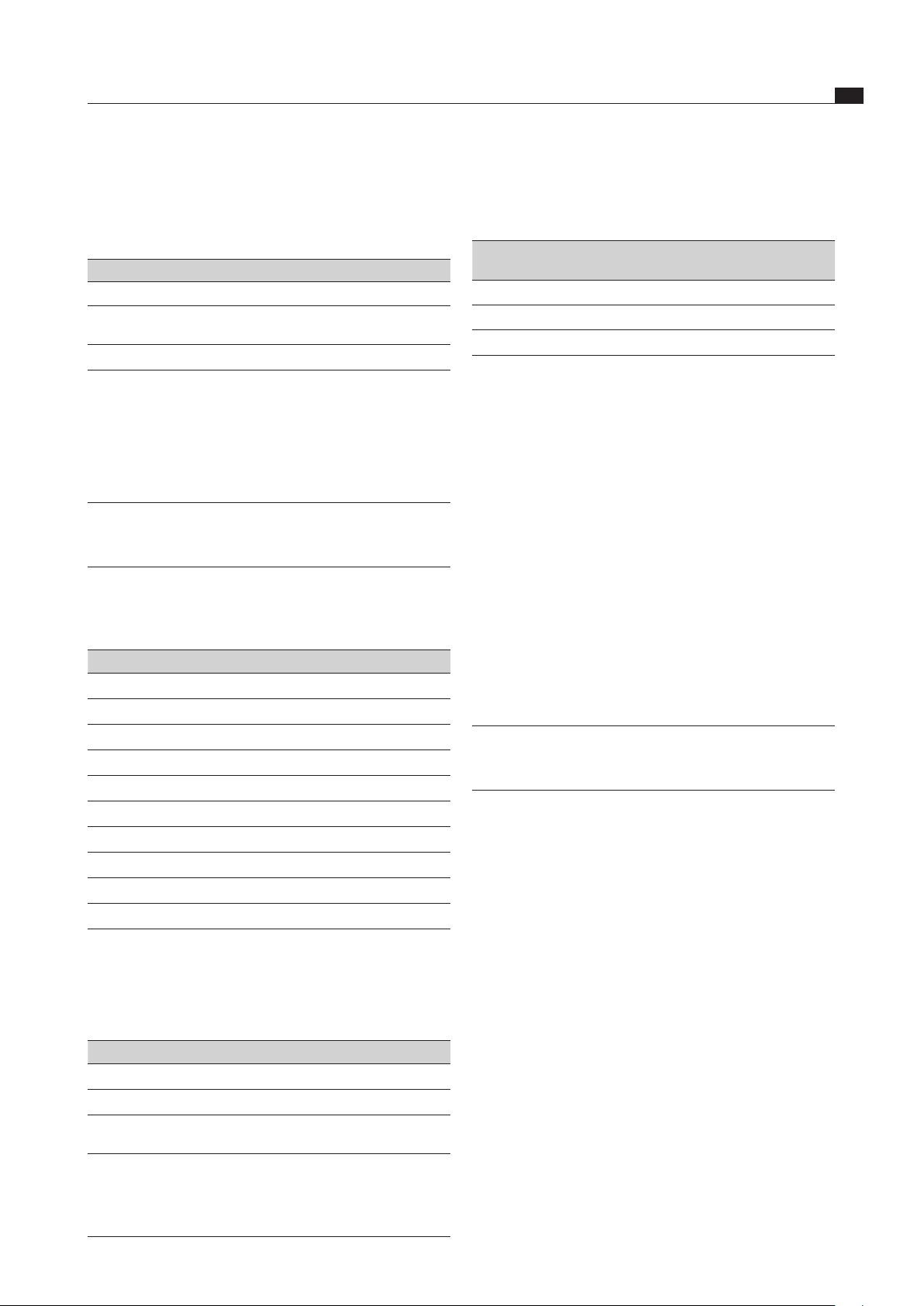
Device dimensions control knob
Ø76
Ø58
Ø49
92
22 10-40 20
Fig. 3.1 Device dimensions control knob
Device dimensions
370
Ø310
540
Fig. 3.2 PKIW1 Device dimensions aerial view
341 14,5
96
128
228 71
Fig. 3.3 PKIW1 Device dimensions front view
511 14,5
371 119
Fig. 3.4 PKIW1 Device dimensions side view
EN
12
Device description
www.bora.com
4 Device description
Observe all safety and warning information during
operation (see the Safety section).
The cooktop has the following features:
Automatic heat up function
Safety shut-down
Electronic power control (9 levels)
Power setting
Childproofing feature
Residual heat display
Stop function
Pan size recognition
Heat retention levels
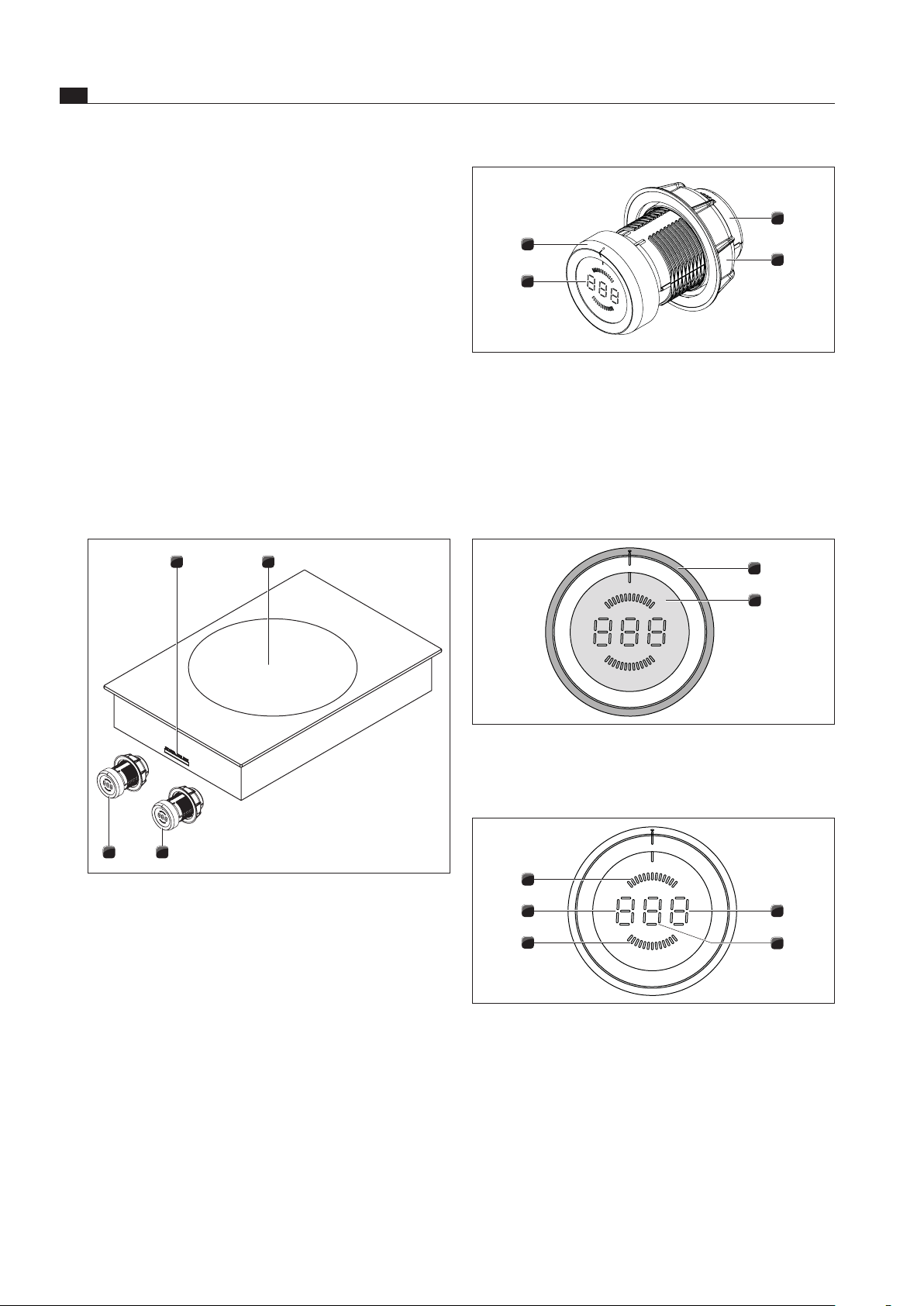
4.1 Structure
3 3
21
Fig. 4.1 Cooktop
[1] Connections for control knob and extraction system
[2] Induction cooking zone
[3] Control knob
4
3
2
1
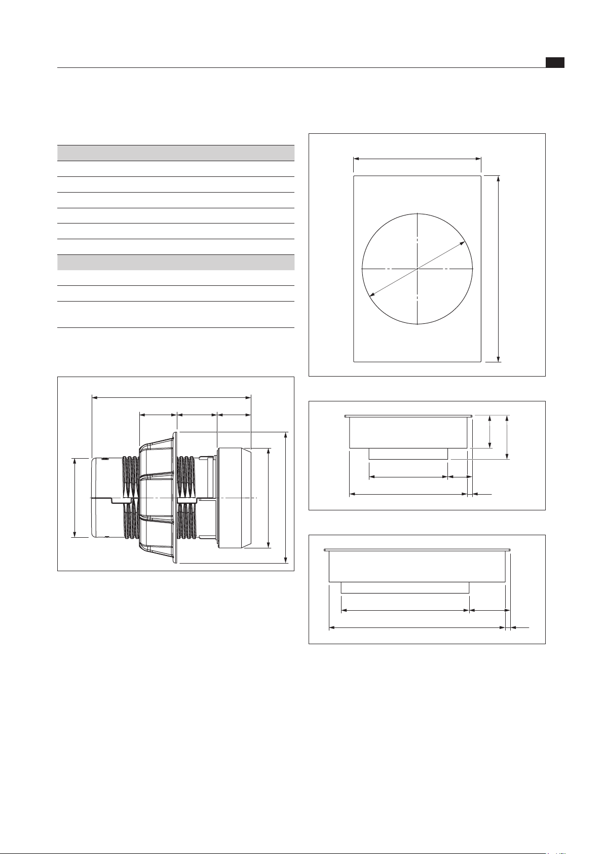
Fig. 4.2 Structure of control knob
[1] Knob casing
[2] Universal nut
[3] Control knob display
[4] knob ring
4.2 Operating principle
2
1
Fig. 4.3 Control elements of control knob
[1] knob ring
[2] Touch surface
5
4
3
2
1
Fig. 4.4 Control knob display elements
[1] Display of functions
[2] Power display
[3] Front cooking zone display
[4] Display of mode or operating mode
[5] Rear cooking zone display
EN
13
Device description
www.bora.com
Activity Power level
Melting of butter and chocolate, keeping food
warm
1
Heating up food
3-6
Roasting food
7-9
Fast roasting of food and roasting of larger
amounts
P
Tab. 4.2 Recommendations for power levels
The specifications provided in the table are standard
values.
Depending on the cookware and filling quantity, it is
recommended to either decrease or increase the power
level.
4.3.2 Power setting
The cooking zone is equipped with a power-enhancing
power setting.
P
appears on the control knob display.
The power setting can be used to quickly heat up large
quantities of food. If the power setting is activated,
the cooking zones will run at extra high power. After
10 minutes, the cooking zone is automatically switched
to power level
9
.
INFO Never heat up oil, fat and the like at this power
setting. The bottom of the pan can overheat
due to the high power output.
4.3.3 Automatic heat up function
The cooking zone is equipped with an automatic heat up
function that can be activated.
The display shows
A
.
This function enables the cooking zone to work at full
power for a certain duration after switching on. After this
time, the power level is automatically switched back to
the power level set.
Power level Cooking duration in min:sec
1
0:40
2
01:00
3
02:00
4
03:00
5
04:20
6
07:00
7
02:00
8
03:00
Tab. 4.3 Overview of the automatic heat up function
Unit Display Meaning
Control knob
display
1 - 9
Power levels
P
Power setting
A
Automatic heat up function
%
Bridging function (PKFI11 only)
t
Short-time timer function (egg
timer)
H
Residual heat display: Cooking
zone is switched off but still hot
(temperature > 60°C)
L
Childproofing feature
I I
Pause function
v
Heat retention level
v
Pan size recognition
C
Configuration menu
0
Cooktop switching off
E
...
Error message (see
Troubleshooting section)
Tab. 4.1 Meaning of display
Knob operation
The cooking zone is operated using a control knob. By
twisting the control knob and pressing the touch surface,
the power levels and functions are controlled (see
Operation section).
INFO As the cooktop only has one cooking zone,
there is only one control knob.
4.3 Functional principle
An induction coil is located underneath an induction
cooking zone. If the cooking zone is switched on, this
coil creates a magnetic field that acts directly on the
base of the pot thus heating it up. The cooking zone is
only indirectly heated up by the heat emitted by the pot.
Cooking zones with induction only work if the cookware
has a magnetisable base.
The induction automatically takes into account the size of
the used cookware which means that only the area in the
cooking zone covered by the base of the pot is heated up.
4.3.1 Power levels
The high power output of induction cooktops results
in the very quick heating up of cookware. A slight
adjustment is needed in comparison to conventional
cooking systems when selecting the power level in order
to avoid burning food.
EN
14
Device description
www.bora.com
Noises
The following noises may occur in the cookware when
using induction cooking zones, depending on the material
and the finish of the base:
Humming may occur when using a high power
level. It decreases or disappears if the power level is
decreased.
Crackling or whistling may occur due to the bases of
cookware made of different materials (e.g. sandwich
base).
Clicking sounds may occur during electronic switching
procedures especially at low power levels.
Whirring may occur when the cooling fan is switched
on. In order to increase the service life of the
electronic system, the cooktop is equipped with a
cooling fan. The cooling fan switches on automatically
if the cooktop is used intensively. You will hear a
whirring sound. The cooling fan may continue running
after the device has been switched off.
4.3.6 Pan size recognition
The cooking zone does not work if
v
is shown in the display.
If it is switched on without cookware or with unsuitable
cookware.
the base diameter of the cookware is too small;
if the cookware is removed from a switched on cooking
zone.
after 10 minutes if no pan is detected. The cooking
zone then switches off automatically and can only
be switched back on after the control knob has been
turned back to the zero position.
4.3.7 Timer functions
There are two different timer functions for each cooking
zone.
t
appears in the control knob display.
INFO You can set a time range of between 1 and
120
minutes for the timer functions.
Timer function
INFO The timer function is an automatic cut-off
which automatically switches off a cooking
zone which is in use.
Short-time timer (egg timer)
INFO The short-time timer requires the cooking
zone to be switched off and works like a
conventional egg timer.
4.3.4 Heat retention levels
The heat retention level keeps cooked foods warm.
v
appears in the control knob display.
The maximum duration for the warming function is
limited to 8 hours.
There are three different heat retention levels.
Heat retention level Symbol Temperature
1
,
42° C
2
;
74° C
3
*
94° C
Tab. 4.4 Heat retention levels
4.3.5 Suitable cookware
INFO The heating and heat through time for the base
of the cookware as well as the cooking results
are significantly influenced by the structure and
material of the cookware.
Cookware with this symbol is suitable for
induction cooktops. The cookware used for
the induction cooktop must be made of metal,
feature magnetic properties and possess a
sufficient bottom surface.
Suitable cookware is made of:
stainless steel with a magnetisable base
enamelled steel
cast iron
Cooking zone Radius
wok 210 mm
Tab. 4.5 Minimum cookware diameter
Perform a magnet test, if necessary. If a magnet sticks
to the base of the utensils, they are normally induction
compatible.
Pay attention to the cookware bottom. The base of
the cookware should not show any sign of curvature.
Due to incorrect temperature monitoring of the hob
caused by the air gap between the cookware and the
temperature sensor underneath the hob, overheating
may occur. The bottom of the cookware must not have
any sharp grooves or sharp edges to avoid scratching
the cooktop.
Place the cookware (without a mat or similar) directly
onto the glass ceramic.
EN
15
Device description
www.bora.com
4.4.3 Overheating protection
The device is fitted with overheating protection.The
overheating protection can be triggered if:
Cookware is heated up empty.
Oil or fat is heated on high power.
A hot cooking zone is switched on again after a power cut.
There is insufficient ventilation below the cooktop (see
Cooktop air intake).
Before the overheating damages the electronics, one of
the following measures is taken:
The power level can no longer be increased.
The power level set is reduced.
The cooktop switches off completely.
After a sufficient cooling period, the cooktop can be used
again in full.
4.4.4 Childproofing feature
Thechildproongfeaturepreventsthecooktopfrom
being switched on accidentally.
L
appears on the control knob display.
Thechildproongfeaturecanonlybeactivatedwhenall
thecookingzonesareswitchedo(seetheOperation
section).
4.3.8 Pause function
The cooking session can be temporarily interrupted (max.
10 minutes).
II
appears on the control knob display.
4.4 Safety devices
4.4.1 Residual heat display
INFO While
H
is displayed in the cooking zone
indicator (residual heat display), do not touch
the cooking zone or place any heat-sensitive
objects on top of it. Risk of burns and fire!
After switching it off, the cooking zone remains hot.
H
is displayed in the control knob display (residual heat
display). The display goes out after a sufficient cooling
time (temperature < 60 °C).
4.4.2 Safety shut-down
Each cooking zone is switched off automatically when the
cooking zone in the power level or heat retention level
exceeds the maximum operating duration. The control
knob display shows
H
(residual heat display).
Power level Switch off after hours:minutes
1
08:24
2
06:24
3
05:12
4
04:12
5
03:18
6
02:12
7
02:12
8
01:48
9
01:13
P
00:10
Tab. 4.6 Safety shut-down for power levels
Heat retention level Switch off after hours:minutes
1 (
,
)
08:00
2 (
:
)
08:00
3 (
*
)
08:00
Tab. 4.7 Safety shut-down for heat retention levels
Switch the cooking zone back on (see Operating
section) if you want to put the cooking zone back into
operation.
EN
16
Installation
www.bora.com
5 Installation
Observe all safety and warning information (see the
Safety section).
Follow the enclosed manufacturer’s information.
INFO The cooktop must not be installed above
cooling devices, dishwashers, stoves, baking
ovens, washing machines or driers.
INFO The contact surface of the worktops and wall
sealing strips must be made of a heat-resistant
material (up to approx. 100 °C).
INFO Worktop cut-outs must be moisture-sealed
using suitable means or, where necessary,
fitted with a thermal insulator.
INFO Control knobs have to be connected only to the
provided connections of the cooktop.
5.1 Checking the scope of delivery
Name Quantity
Control knob 2
Operating and installation instructions 1
Cooktop fixing screws 4
Height adjustment plate set 1
Cooktop 1
Cooktop mounting straps 4
Control knob cable 2
Automatic extraction system cable 1
Cleaning instructions for glass ceramic 1
Glass ceramic scraper 1
Tab. 5.1 Scope of delivery
Check the delivered items for damage and make sure
that everything has been received.
If there are any missing or damaged parts, please
notify BORA After Sales Service immediately.
Do not under any circumstances install parts which are
damaged.
Dispose of transport packaging in the proper manner
(see the Decommissioning and Disposal section).
5.2 Tool and aids
The following tools are required to correctly install the
cooktop:
Pencil
Measuring instrument
Standard or cordless drill with Forstner bit Ø 50 mm
Screwdriver/hexalobular wrench (torx) 20
Silicone sealant for sealing cutting surfaces
5.3 Assembly instructions
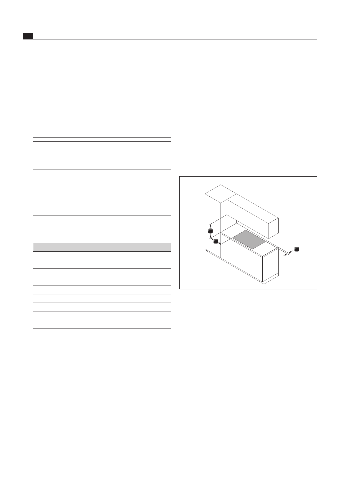
5.3.1 Safety clearances
Maintain the following safety clearances:
1
3
2
Fig. 5.1 Minimum clearances
[1] Minimum clearance of 50 mm at the back from the worktop
cut-out to the rear edge of the worktop.
[2] Minimum clearance of 300 mm from the left and right of the
worktop cut-out to the adjacent cabinet or wall.
[3] Minimum clearance of 600 mm between the worktop and
the wall unit.
5.3.2 Work surface and kitchen units
Create the worktop cut-out taking the specified cut-out
dimensions into account.
Make sure that the cutting surfaces of the worktops
are properly sealed.
Observe the instructions provided by the worktop
manufacturer.
Cross bars on the unit in the area of the worktop cut-
out may need to be removed.
A false floor underneath the cooktop with integrated
cooktop extractor is not needed.
If a cable protection shelf (false floor) is planned for
under the devices, this must be installed so as to be
removable for maintenance work.
The drawers and/or shelves in the floor unit must be
removable.
EN
17
Installation
www.bora.com
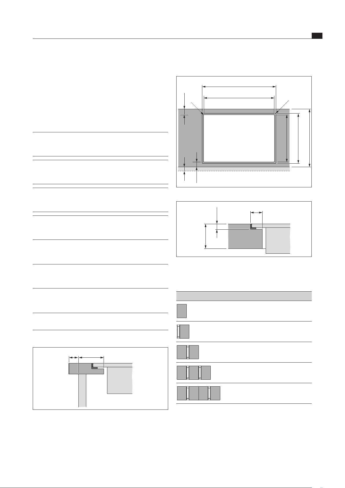
5.4.1 Flush installation
x
A ±2
B ±2
544 ±2
≤ R5
≤ R5
≥ 74
≥ 74
516 ±2
≥ 700
Fig. 5.3 Cut-out dimensions ush installation
7 +0,5
14
10 - 40
Fig. 5.4 Groove dimensions for ush installation
Cut-out dimensions when installing cooktops or cooktops
and the cooktop extractor next to each other:
Cooktops/cooktop extractor A in mm B in mm
1/0 374 346
1/1 485 457
2/1 856 828
3/2 1338 1310
4/2 1709 1681
Tab. 5.2 Cut-out dimensions appliance combinations ush
installation
A return flow aperture > 500 cm
2
is required in the
kitchen units for recirculation appliances (e.g. by
shortening the plinth boards or using suitable slatted
plinths).
5.3.3 Cooktop air intake
The components in the cooktop which generate heat are
automatically cooled. The warm air is extracted by fans
(cold air flow).
INFO In order to retain the full functionality of
the cooktop in the long term, there must be
sufficient ventilation underneath the cooktop.
INFO The performance of the cooktop is impaired or
the cooktop overheats if the warm air below
the cooktop cannot escape.
INFO If the cooktop overheats, performance
is reduced or the cooktop switches off
completely (see Overheating protection).
INFO For sufficient air intake, an opening cross-
section in the kitchen units of at least 50 cm
2
is recommended.
Ensure there is sufficient ventilation underneath the
cooktop.
INFO If there are plans for a cable protection floor
(false floor) below the device, this must not
impede the ventilation.
5.4 Cut-out dimensions
INFO All dimensions from the front edge of the front
cover.
Worktop overhang
≥ 74x
Fig. 5.2 Worktop overhang
Please note the worktop overhang x when creating
the worktop cut-out. Applies to flush installation and
surface mounting.
EN
18
Installation
www.bora.com
5.5 Installing the cooktop
INFO Clearance of one millimetre should be planned
between the built-in appliances.
In combination with an adjacent PKA/PKAS
cooktop extractor, the plastic strip on the side
of the cooktop extractor must be carefully
removed for this (see ‘Removing the plastic
strip from the side of the cooktop extractor’).
INFO A clearance of two millimetres should be
planned around the built-in appliances.
INFO A mounting rail should ideally be installed
between adjacent cooktops (PZMS mounting
rail available as an accessory).
INFO Alternatively, the cooktop can be installed with
just one control knob.
INFO Alternatively, the cooktop can be installed
rotated by 180°.
5.5.1 Removing the plastic strip from the
side of the cooktop extractor
INFO The plastic strip on the side of the cooktop
extractor only has to be removed if the
induction glass ceramic wok cooktop is
installed right next to the cooktop extractor.
2
1
Fig. 5.7 Removing the plastic strip from the side of the
cooktop extractor
[1] Side plastic strip
[2] Cooktop extractor
5.4.2 Surface mounting
x
B ±2
≤ R5
≥ 74
≥ 74
516 ±2
≥ 700
Fig. 5.5 Cut-out dimensions surface mounting
12
10 - 40
Fig. 5.6 Surface mounting cut-out
Cut-out dimensions when installing cooktops or cooktops
and the cooktop extractor next to each other:
Cooktops/cooktop extractor B in mm
1/0 346
1/1 457
2/1 828
3/2 1310
4/2 1681
Tab. 5.3 Cut-out dimensions appliance combinations surface
mounting
EN
19
Installation
www.bora.com
Installation with 1 control knob
Fig. 5.10 Installed cooktop with 1 control knob
≥70
Ø50 ±0,5
370
Fig. 5.11 Drilling diagram
[1] Cooktop
[2] Worktop
[3] Floor unit’s panel
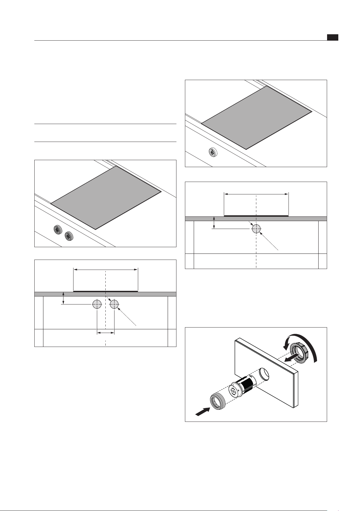
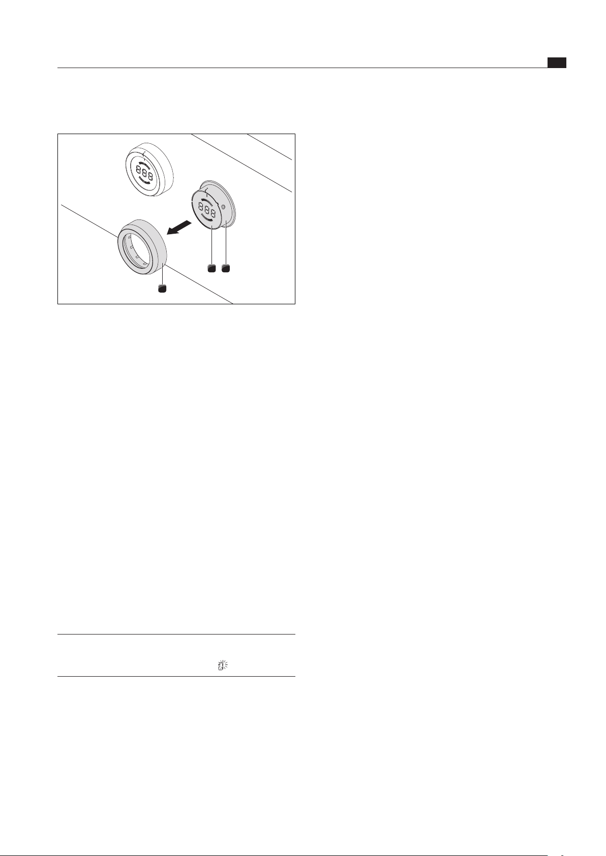
Installing the control knob
Fig. 5.12 Installing the control knob
Pull off the selector ring.
Unscrew the fixing nut.
Push the control knob through the drilled hole in the
floor unit’s panel from the front.
Screw the fixing nut onto the control knob from the
back and lightly tighten it.
Carefully remove the plastic strip [1] from the side of
the cooktop extractor [2].
Use a Stanley knife or similar suitable tool to assist
you.
5.5.2 Installing the control knob behind the
floor unit’s panel
INFO Pre-drill the bore holes to prevent tearing out
the panel.
Installation with 2 control knobs
Fig. 5.8 Installed control knobs and cooktop
≥70
Ø50 ±0,5
370
80-140
Fig. 5.9 Drilling diagram
[1] Cooktop
[2] Worktop
[3] Floor unit’s panel
EN
20
Installation
www.bora.com
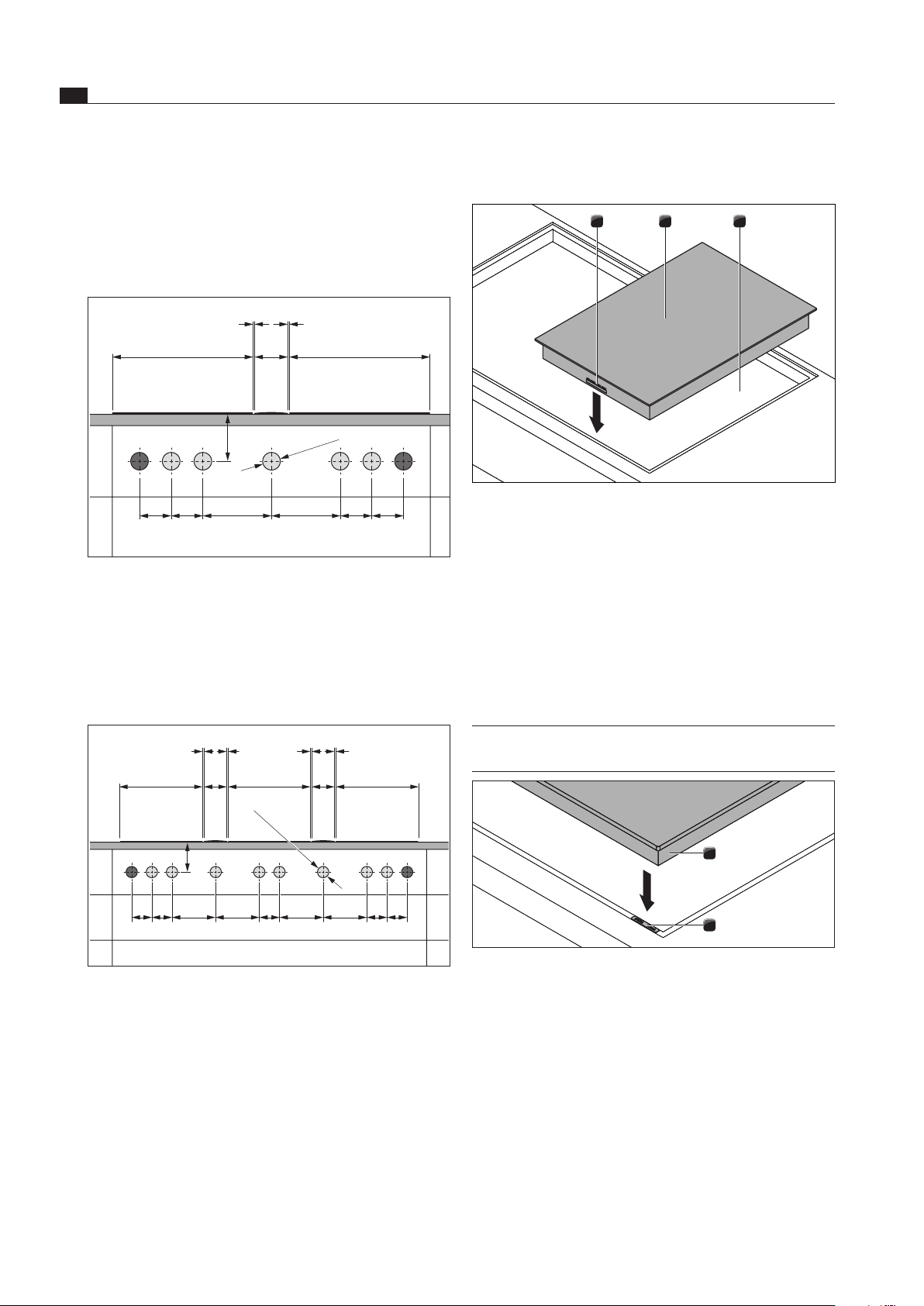
5.5.3 Installing the cooktop
321
Fig. 5.15 Inserting the cooktop
[1] Connections for the control knob and automatic extraction
system (at the front)
[2] Cooktop
[3] Worktop cut-out
Insert the cooktop [2] into the worktop cut-out [3].
Precisely align the cooktop [2].
Please note that during normal installation, the
connections for the control knob and the automatic
extraction system [1] are at the front.
INFO The device connector should be fed backwards.
Do this using the cable brackets provided.
1
2
Fig. 5.16 Cooktop and height adjustment plates
[1] Cooktop
[2] Height adjustment plates
If applicable, insert the height adjustment plates [2].
Vertically align the control knob in the 12 o’clock
position based on the markings.
Tighten the fixing nut.
Place the selector ring on the control knob.
Bore hole examples
≥70
90 90 90
Ø50 ±0,5
90 196 196
370 370
110
1 1
Fig. 5.13 Bore holes for 2 cooktops and 1 extractor
[1] Bore holes for socket (2x external)
[2] Bore holes for control knobs (5x)
[3] Cooktop (2x)
[4] Cooktop extractor
[5] Worktop
[6] Floor unit’s panel
≥70
90 90 909090 196 196 196 196
370 370
370
110
1 1 1 1
110
Ø50 ±0,5
Fig. 5.14 Bore holes for 3 cooktops and 2 extractors
[1] Bore holes for socket (2x external)
[2] Bore holes for control knobs (8x)
[3] Cooktop (3x)
[4] Cooktop extractor (2x)
[5] Worktop
[6] Floor unit’s panel
EN
21
Installation
www.bora.com
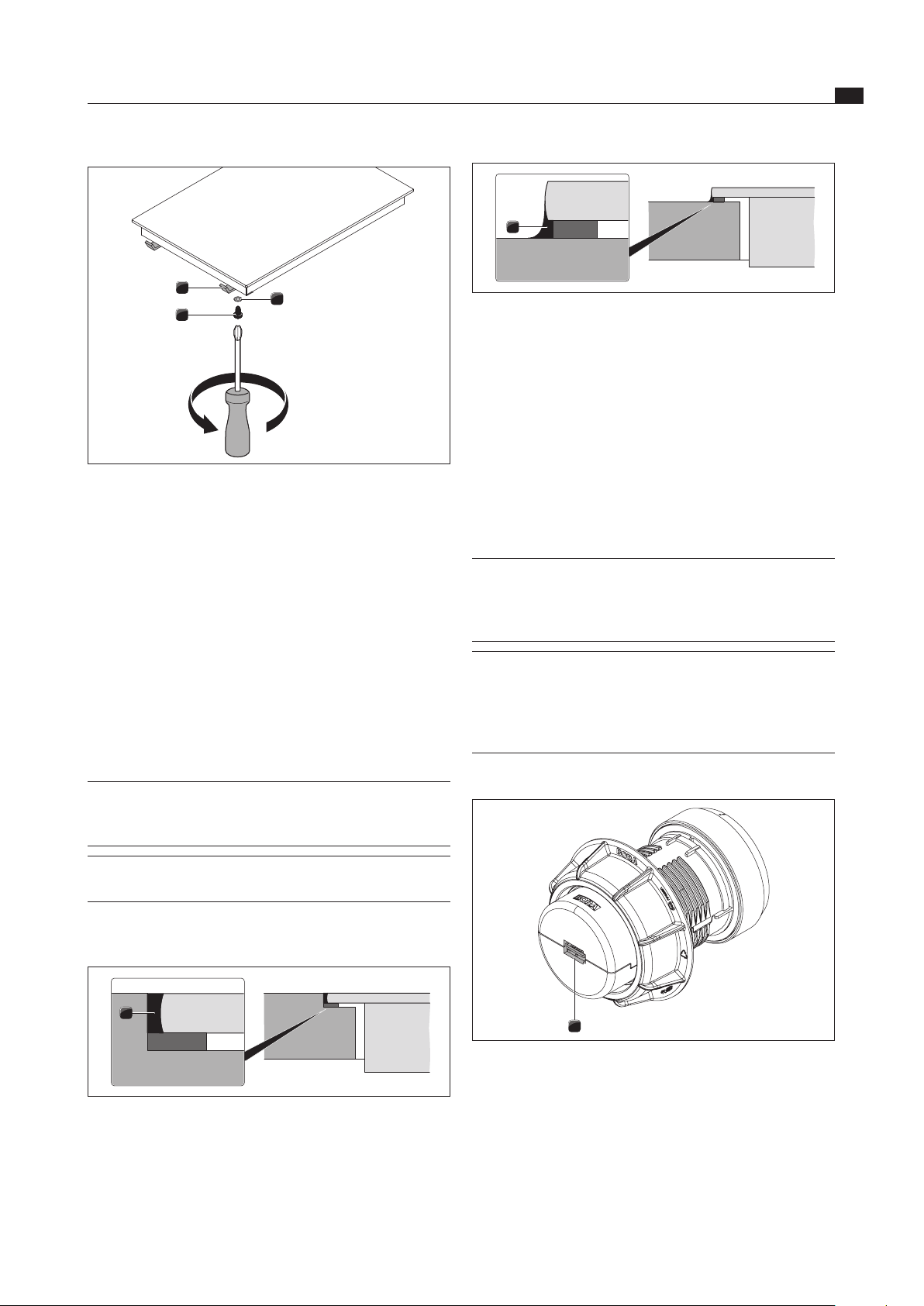
1
Fig. 5.19 Silicone sealant with surface mounting
[1] Black, heat-resistant silicone sealant
5.5.5 Establishing communications
The device components are connected using the flat-
ribbon cable supplied in the scope of delivery.
Create the connection between the cooktop and the
control knobs.
Create the connection between the cooktop and the
cooktop extractor.
Connecting the cooking zones
INFO If the PKIW1 Professional induction wok
cooktop has been installed with 2 control
knobs, it can be operated with both the left and
the right control knob.
INFO As the induction wok cooktop only has one
cooking zone, there is no need to pay attention
to the assignment of the connections when
connecting 2 control knobs (see the Operation
section).
Connection on the control knob
1
Fig. 5.20 Control knob connection at the back
[1] Control knob connection at the back
1
3
2
Fig. 5.17 Mounting brackets
[1] Mounting bracket
[2] Washer
[3] Screw
Affix the cooktop using the mounting brackets [1].
Use the screw [3] and the washer [2] to tighten the
mounting brackets with max. 10 Nm.
Check that the cooktop is positioned correctly.
Once all of the installation work is complete, seal the
devices with black, heat-resistant silicone sealant.
Installation rotated by 180°
Rotate the cooktop by 180°.
Conduct the installation as described.
INFO If the device is installed rotated by 180°, the
connections for the control knob and the
automatic extraction system are at the back.
INFO The scope of delivery includes sufficiently long
cables.
5.5.4 Sealing the cooktop
Ensure that no silicone sealant gets under the cooktop.
1
Fig. 5.18 Silicone sealant with ush installation
[1] Black, heat-resistant silicone sealant
EN
22
Installation
www.bora.com
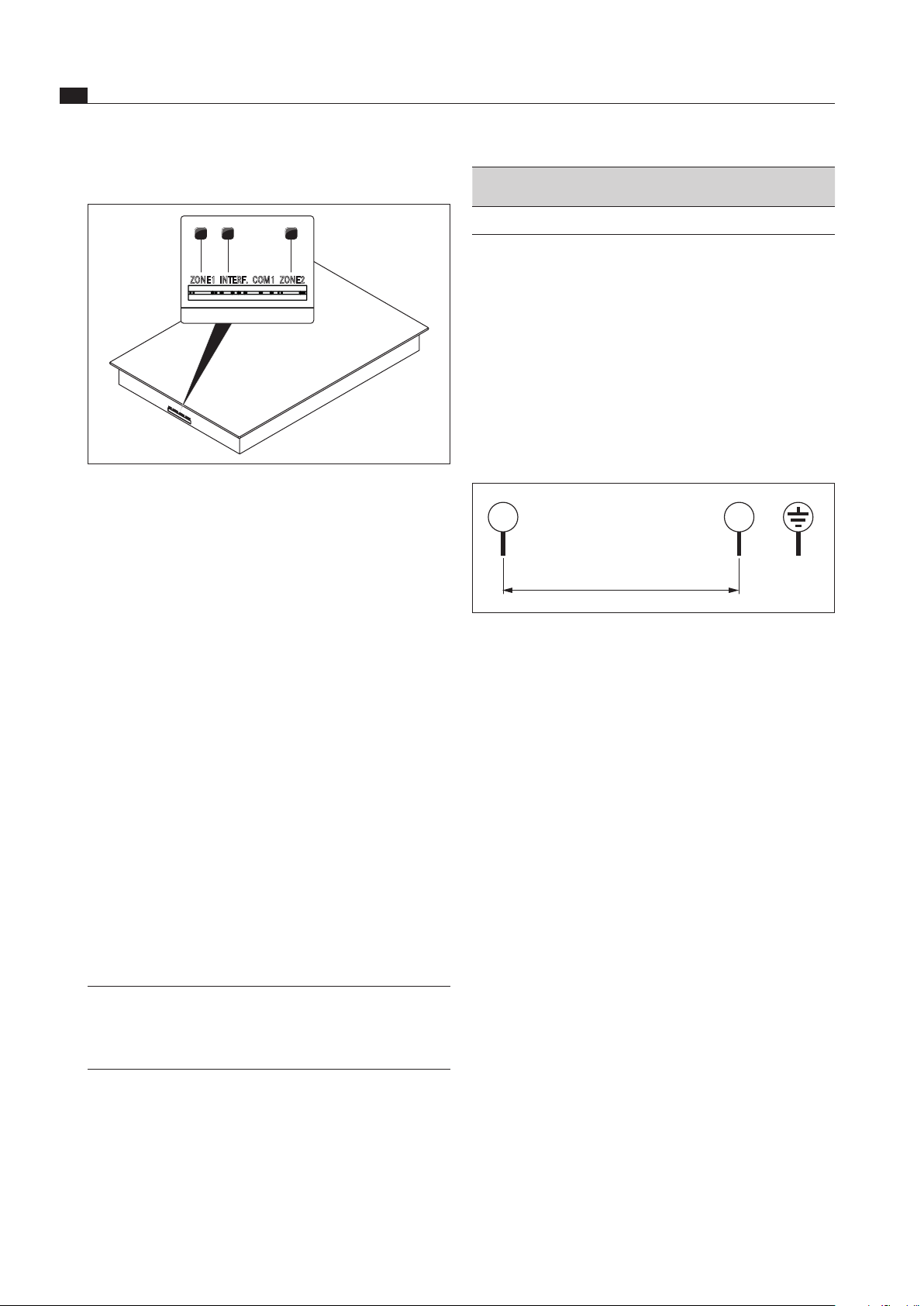
Connections on the cooktop
321
ZONE1 INTERF. COM1 ZONE2
Fig. 5.21 Connections on the cooktop
[1] Control knob connection for the front cooking zone (zone 1)
[2] Connection for the automatic extraction system
[3] Control knob connection for the rear cooking zone (zone 2)
Cooking zone connection with 1 control knob
Connect the connection on the back of the control
knob with one of the connections on the cooktop (zone
1 or zone 2).
Cooking zone connection with 2 control knobs
Connect the connections on the back of the control
knobs with the connections on the cooktop (zone 1
and zone 2).
Connecting the automatic extraction system
Connect the cooktop extractor to the connection
provided for the automatic extractor system on the
cooktop.
5.5.6 Establishing the power connection
Observe all safety and warning information (see the
Safety section).
Observe all national and regional laws and regulations
as well as the supplementary regulations of the local
utility companies.
INFO The power connection may only be established
by certified specialists. The specialist
also assumes responsibility for the proper
installation and commissioning.
The power supply line to be used (pre-assembled) must
be at least type H05VV-F or H05VVH2-F (see the Fuse
protection and minimum cross-section table).
Connection Fuse protection Minimum
cross-section
1-phase connection 1 x 16 A 1.5 mm
2
Tab. 5.4 Fuse protection and minimum cross-section
If the connection cable has been damaged, it must
be replaced. This may only be done by an authorized
member of the After Sales Service team.
Switch off the main switch/automatic circuit breaker
before connecting the cooktop.
Secure the main switch/automatic circuit breaker
against being switched back on without permission.
Make sure the power to the appliance is disconnected.
Only connect the cooktop using a permanent
connection to a power supply cable.
1
L1
2
N PE
220 - 240 V~
Fig. 5.22 Connection diagram 1-phase
Check that installation has been done correctly.
Switch on the main switch/automatic circuit breaker.
Put the cooktop into operation (see the Operation
section).
Check that all the functions are working correctly.
5.6 Configuration menu
Once installation is complete, you can configure certain
basic settings for your cooktop, which you can also
change again at any time.
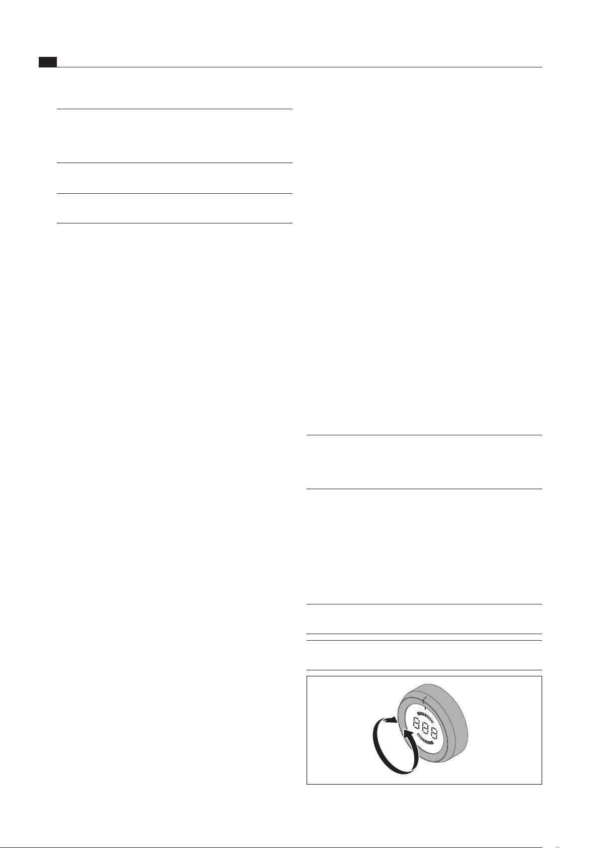
5.6.1 Opening the configuration menu
Turn the control knob to the 11 o’clock position.
t
appears on the control knob display.
Tap the control knob’s touch-operated area. The
display switches to
000
.
Press the touch-operated area again within 3 seconds,
retaining contact with it for 5 seconds.
C
appears on the control knob’s display, an acoustic
signal sounds and the configuration menu opens.
EN
23
Installation
www.bora.com
5.6.2 Selecting a menu item
Select the desired menu item by turning the selector
ring.
The following menu items are available for selection:
Menu items
C
0
Acoustic signal volume
C
1
Select an operating mode (normal operation or demo
mode)
C
9
Availability of the pause function
Tab. 5.5 Menu items in the conguration menu
Tap the touch-operated area to confirm the selected
menu item.
The submenu opens and the display switches to a
three-digit combination (e.g.
C23
).
INFO In the three-digit combination displayed, the
digit on the right indicates the value saved in
the system.
Setting the volume of the acoustic signal
If you have confirmed menu item
C0
, you can set the
volume of the acoustic signal.
Setting Acoustic signal volume
C
0
0
100% (max. volume) Factory default
C
0
1
10% (min. volume)
C
0
2
20%
C
0
3
30%
C
0
4
40%
C
0
5
50%
C
0
6
60%
C
0
7
70%
C
0
8
80%
C
0
9
90%
Tab. 5.6 Acoustic signal volume
Selecting the operating mode
If you have confirmed menu item
C 1
, you can select the
operating mode.
Setting Operating mode
C
1
0
Normal operation Factory default
C
1
1
Demo mode
Tab. 5.7 Operating modes
INFO All control knob functions are available in
demo mode. The cooktop’s heating function
is deactivated. The demo mode is used for
showrooms, for example.
Availability of the pause function
If you have confirmed menu item
C9
, you can permanently
deactivate the pause function.
Setting Pause function available/deactivated
C
9
0
Pause function activated Factory default
C
9
1
Pause function deactivated
C
9
2
Pause function with power display activated
Tab. 5.8 Availability of the pause function
5.6.3 Changing the set value
Turn the selector ring clockwise to increase the value.
Turn the selector ring anti-clockwise to reduce the
value.
Tap the touch-operated area to confirm the new value.
The value is saved and an acoustic signal sounds.
The previously selected menu item reappears on the
control knob display.
5.6.4 Exiting the configuration menu
Turn the selector ring until
C
appears on the display.
Now tap the touch-operated area to exit the
configuration menu. The display goes out and an
acoustic signal sounds.
Turn the selector ring to the 12 o’clock position.
0
appears on the display for 10 seconds. The display
then goes out and an acoustic signal sounds.
INFO If no settings are made in a menu or submenu
item for 2 minutes, the device automatically
exits the configuration menu.
5.7 Handover to user
Once installation is complete:
Explain the main functions to the user.
Explain all safety-related aspects of operation and
handling to the user.
Stick the supplied nameplate to the back of these
operating and installation instructions.
Provide the user with the accessories and operating
and installation instructions to be kept in a safe place.
EN
24
Operation
www.bora.com
6 Operation
Observe all safety and warning information during
operation (see the Safety section).
INFO The cooktop may only be operated when
the stainless steel grease filter of the
cooktop extractor is installed (see operating
instructions for cooktop extractor).
INFO Clean the cooking zone before using the
cooktop for the first time (see the Cleaning
section).
6.1 General operating instructions
INFO As the cooktop only has one cooking zone,
there is only one control knob.
INFO If two control knob are fitted, a cooking session
is operated using the control knob which is
used first. If the knob ring is moved to the
12 o’clock position (= 0 position), the device
can be controlled using the other control knob.
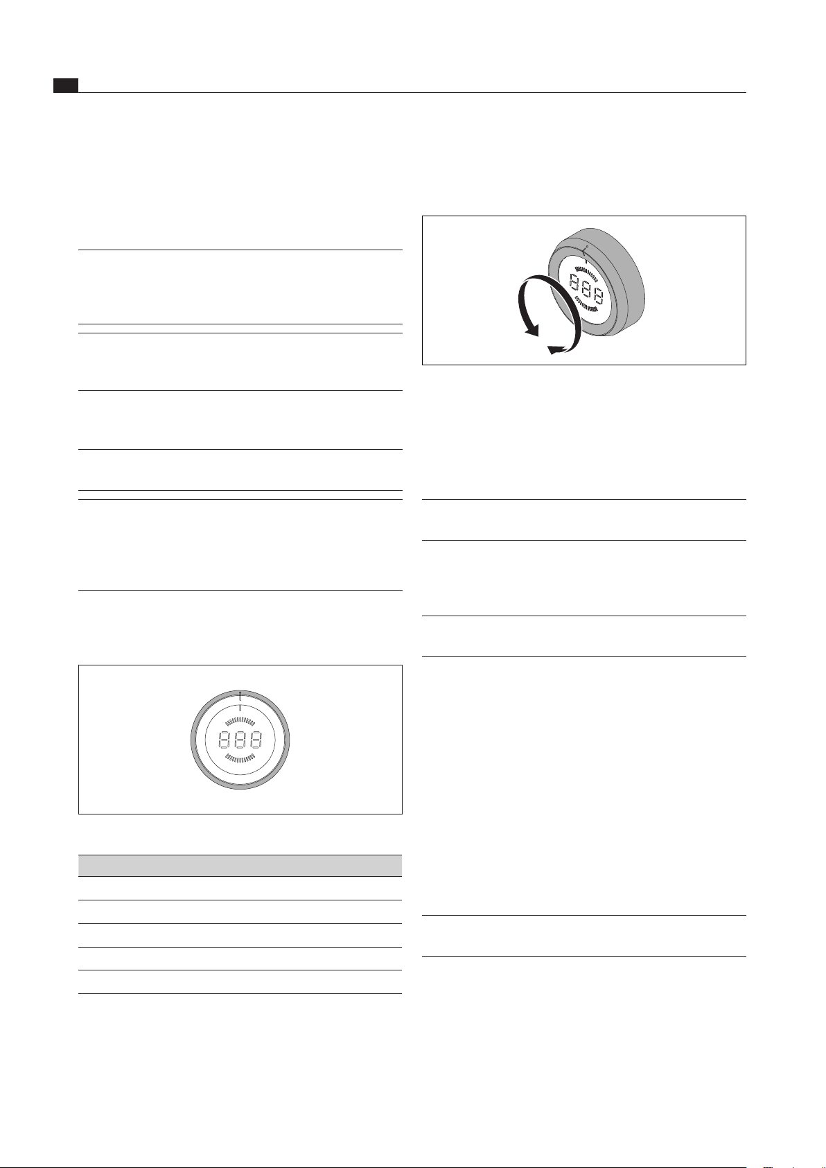
The cooktop is controlled using the control knobs.
There are 9 power levels, one power setting and various
functions available for the cooking zone.
t
P
9
8
7
6
5
4
3
2
1
v
0
Fig. 6.1 Knob ring assignment
Knob ring position Function
0
Switching off
v
Heat retention level
1 - 9
Power levels
P
Power setting
t
Timer function
Tab. 6.1 Knob ring positions
6.2 Operating the cooktop
6.2.1 Switching on the cooking zone
Fig. 6.2 Switching on the cooking zone
Turn the knob ring from the 12 o-clock position to a
power level.
Adjusting the power level
Turn the knob ring to the desired power level.
INFO Power levels are shown in the middle
7 segment display on the control knob.
6.2.2 Power setting
Switching on the power setting
INFO The cooking zone is equipped with a
power-enhancing power setting.
Twist the knob ring to the 10 o’clock position.
The control knob display shows
P
and the power
setting is activated.
After 10 minutes, the cooking zone is automatically
switched back to power level
9
.
Switching the power setting off early
Turn the knob ring to the desired power level.
The power level set is active and is shown in the
control knob display.
6.2.3 Automatic heat up function
Switching on the automatic heat up function
INFO The exact values for the heat-up time can be
found in the Device description section.
Select the desired power level (= later continuous
cooking level).
Within 3 seconds of setting the power level, press the
touch surface of the control knob for at least 1 second.
The automatic heat up function is activated and the
control knob shows an
A
in front of the continuous
cooking level selected (e.g.
A3
).
EN
25
Operation
www.bora.com
Increase heat retention level
Press the touch surface on the control knob a second
time for 1 second to activate heat retention level 2 (
;
).
Press the touch surface on the control knob a third
time for 1 second to activate heat retention level 3 (
*
).
Each time, this is confirmed by a beep and the relevant
symbol is shown on the control knob display.
Reduce heat retention level
After setting heat retention level 3, pressing the touch
surface (1 second) again reduces the level by 1.
Each time, this is confirmed by a beep and the relevant
symbol is shown on the control knob display.
Switching off heat retention level
The heat retention level activated switches off if you
select another power level
switch off the cooking zone
6.2.5 Childproofing feature
INFO The childproofing feature can only be activated
or permanently deactivated if both knob brings
are at the 12 o’clock position and no function
is active.
Activating the childproofing feature
Press the touch surface of one of the control knob for
5 seconds.
An acoustic signal can be heard and the display on
the control knob switches to
L
. The display goes blank
after 10 seconds and the childproofing feature is
activated.
Permanently deactivating the childproofing
feature
Press the touch surface of one of the control knob for
5 seconds.
A beep can be heard and the display on the control
knob switches to
0
. The display goes blank after
10 seconds and the childproofing feature is
permanently deactivated.
Deactivating the childproofing feature for a
cooking session
Turn the knob ring from the 12 o-clock position to a
power level.
L
appears in the control knob display.
Press the touch surface of the control knob for
5 seconds.
An acoustic signal can be heard and the control knob
display shows the power level selected.
The childproofing feature is only deactivated for this
cooking session and you can set the power level you
want.
The childproofing feature is reactivated next time you
switch on.
INFO An
A
is shown on the control knob display for
as long as the automatic heat up function is
active.
Once the automatic heat up period has passed, the
power is reduced to the selected continuous cooking
level.
If a higher continuous cooking level is selected while
the automatic heat up function is active, the new heat-
up time is automatically valid.
Switching off the automatic heat up function
The activated automatic heat up function will end
prematurely if you
reduce the power level (continuous cooking level).
set power level
9
.
activate power setting
P
.
activate heat retention level
v
.
switch off the cooktop.
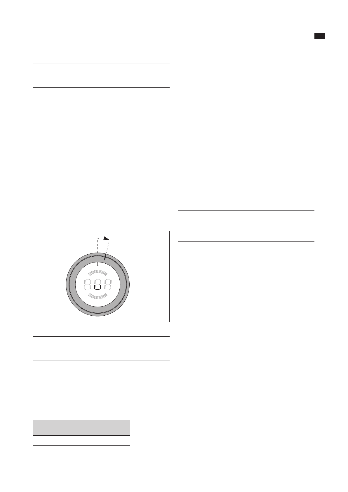
6.2.4 Heat retention level
Activating the heat retention level
15°
Fig. 6.3 Knob ring setting for heat retention level
INFO The knob ring position for the heat retention
level is between the 12 o’clock position and
the 1 o’clock position.
Turn the selector ring approximately 15° clockwise
from the 12 o’clock position until it lightly engages.
v
appears in the control knob display.
Press the touch surface on the control knob for 1
second to activate the heat retention level 1.
This is confirmed by a beep and the
,
symbol is sown
on the control knob display.
Heat retention
level
1 2 3
Symbol
. ; *
Temperature in °C 42 74 94
Tab. 6.2 Temperatures of heat retention levels
EN
26
Operation
www.bora.com
Activating the short-time timer (egg timer)
Once you have confirmed the time set, you have
3 seconds to turn the knob ring to the 12 o’clock
position.
This activates the short-time timer and the time starts
to count down.
The displays shows remaining time (accurate to the
minute for more than 2 minutes and accurate to the
second for under 2 minutes).
At the end of the time, a beep sounds for 2 minutes
and the control knob display flashes
000
.
The flashing and the beeping can be stopped by
pressing the touch surface.
Switching off the short-time timer (egg timer) early:
Press the touch surface of the knob ring.
The short-time timer is deactivated.
The control knob display shows
0
and a beep sounds.
6.2.7 Pause function
Activate pause function
Press the touch surface of the control knob for
1 second.
An acoustic signal sounds and
11
appears on the
control knob’s display.
The cooking session is interrupted.
INFO The cooking session can be paused for a
maximum of 10 minutes. If the pause function
is not deactivated in this time, the relevant
cooking zone is switched off.
Deactivate pause function
Press the touch surface of the control knob for
1 second.
A beep sounds and the power level selected is shown
on the control knob display.
The cooking session continues.
6.2.8 Switching off the cooking zone
INFO If a cooking zone indicator shows
H
,
the cooking zone is still hot.
INFO Turn the cooking zone off after use.
Do not rely on the pan size recognition.
Fig. 6.4 Switching o the cooking zone
INFO If the cooktop is switched off at the end of the
cooking session (turn the selector ring to the
12 o’clock position), the childproofing feature
is automatically re-activated.
6.2.6 Using the timer function
INFO You can set a time range of between 1 and
120 minutes for the timer functions.
Set time
Twist the knob ring to the 11 o’clock position.
t
appears on the control knob display.
Press the touch surface for one second.
A beep can be heard and the control knob display
switches to
000
.
Within 3 seconds, twist the knob ring to set the timer time.
Turning clockwise increases the time (starting at
0 minutes), while turning anticlockwise reduces the
time (starting at 120 minutes).
In the range from 0 to 20 minutes, the time reduces/
increases in both directions by one minute at a time, while
the increments are 5 minutes for the rest of the range.
If no time is set within 3 seconds, the timer is
deactivated and the control knob display switches to
t
.
Press the touch-surface within 3 seconds to confirm
the time set.
A beep sounds and the set value starts to flash on the
control knob display.
Activating the timer function
Once you have confirmed the time set, you have
3 seconds to turn the knob ring to the power level
you want.
This activates the timer function and the time starts
to count down.
The displays swaps (for 3 seconds each) between the
power level and the remaining time (accurate to the
minute for more than 2 minutes and accurate to the
second for under 2 minutes).
Once the remaining time is less than 2 minutes, only
the time is displayed.
At the end of the time, the cooking zone is switched
off, a beep sounds for 2 minutes and the control knob
display flashes
000
.
The flashing and the beeping can be stopped by
pressing the touch area or twisting the knob ring to
the 12 o’clock position.
Switching the timer off early:
Twist the knob ring to the 12 o’clock position.
The control knob display changes to
0
, a beep sounds
and the cooking zone switches off.

EN
27
Operation
www.bora.com
Twist the knob ring to the 12 o’clock position.
A beep sounds and the cooking zone is deactivated.
The cooktop is switched off when there are no longer
any active cooking zones.
Pay attention to the residual heat display
(see the Device Description section).
6.3 Configuration menu
see the Installation section

EN
28
Cleaning and maintenance
www.bora.com
7 Cleaning and
maintenance
Observe all safety and warning information
(see the Safety section).
Follow the enclosed manufacturer’s information.
When conducting scheduled cleaning and other
maintenance, make sure that the cooktop and cooktop
extractor are fully switched off so as to prevent injury
(see Operation section).
Regular cleaning and maintenance ensures the
longevity of the product and optimal function.
Adhere to the following cleaning and maintenance
cycles:
Component Cleaning cycle
Control knob Cooktop immediately they become dirty with
conventional detergents
Tab. 7.1 Cleaning cycles
7.1 Cleaning agents
INFO Due to the use of aggressive cleaning agents
and abrasion caused by the pot bases the
surface will become damaged and dark stains
will occur.
INFO Do not use the glass ceramic scraper in the
curved area of the Wok cooking zone.
To clean the cooktop, you need a special glass ceramic
scraper and suitable detergents.
Never use steam cleaners, abrasive sponges, scouring
pads or chemically aggressive cleaning agents
(e.g. oven cleaner spray).
Make sure that the cleaning agent does not contain
any sand, soda, acids, lyes or chloride.
7.2 Looking after the cooktop
Never use the cooktop as a work or storage surface.
Do not push or pull cookware over the cooktop.
Always lift pots and pans.
Keep the cooktop clean.
Remove any dirt immediately.
Only use cookware suitable for glass ceramic cooktops
(see Device description section).
7.3 Cleaning the cooktop
Make sure that the cooktop is switched off
(see the Operation section).
Wait until all cooking zones are cold.
Remove all coarse dirt and food residues from the
cooktop using a glass ceramic scraper.
Put the detergent onto the cold cooktop.
Spread the detergent using kitchen roll or a clean
cloth.
Rinse the cooktop off with water.
Dry the cooktop with a clean cloth.
If the cooktop is hot:
remove stubborn residues of plastic, aluminium foil,
sugar or sweet dishes from the hot cooking zone
immediately using a glass ceramic scraper to prevent
burning.
Heavy soiling
Remove heavy soiling and marks (limescale marks,
mother-of-pearl like shiny marks) using detergents
while the cooktop is still warm.
Wipe off food that boils over with a wet cloth.
Remove any remaining dirt with the glass ceramic
scraper.
Always remove seeds, crumbs or similar which fall onto
the cooktop during cooking immediately to prevent the
surface getting scratched.
Any changes in colour or glossy spots are not damage to
the cooktops. They do not affect the functionality of the
cooktop or the stability of the glass ceramic panel.
Changes in the colour of the cooktop are the result of
residue which has not been removed and has burnt on.
Glossy spots are the result of wear by the pan base,
especially if aluminium-based cookware or unsuitable
detergents are used. It is hard work to remove them.
EN
29
Cleaning and maintenance
www.bora.com
7.4 Cleaning the control knobs
12
3
Fig. 7.1 Pull out the knob ring
[1] Knob casing
[2] Touch surface
[3] knob ring
7.4.1 Cleaning the knob ring
The knob ring can only be cleaned by hand.
Remove the knob ring from the knob housing.
Use a cleaner and degreaser in one.
Rinse the knob ring in hot water.
Clean the knob ring with a soft brush.
Rinse the knob ring well after cleaning.
Dry the knob ring carefully.
Place the dry knob ring back on the knob housing.
Make sure it is positioned correctly (0 position).
If necessary, twist the knob ring to the 12 o’clock
position (= 0 position).
7.4.2 Cleaning the touch surface and the
knob housing
Pull off the knob ring.
Clean the touch surface and the knob housing with a
soft, damp cloth.
Dry the touch surface and the knob housing carefully.
Place the knob ring back on the knob housing.
INFO If the knob ring has not been fitted correctly, a
segment rotating clockwise is displayed in the
central control knob display .
EN
30
Troubleshooting
www.bora.com
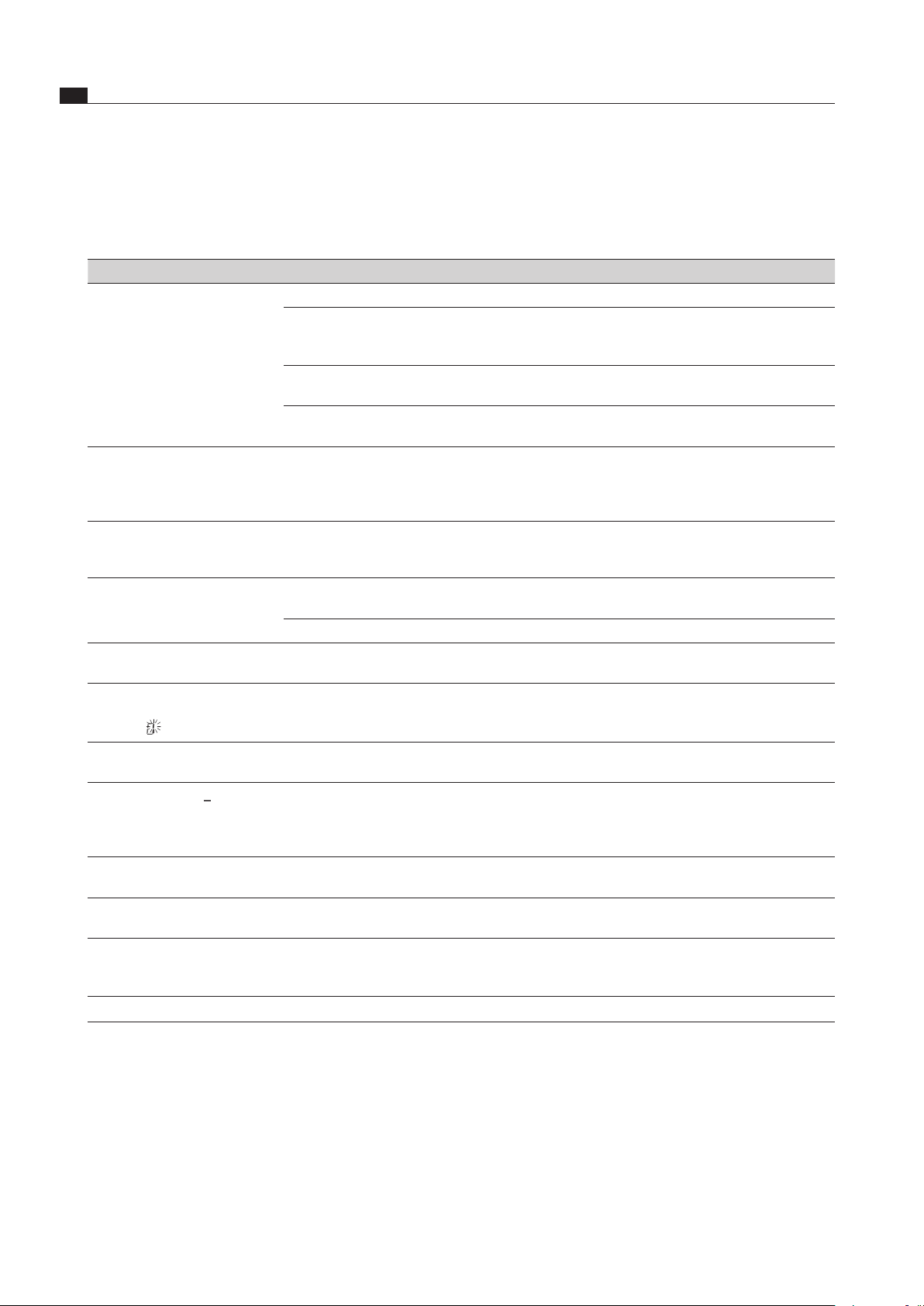
8 Troubleshooting
Observe all safety and warning information (see the Safety section).
Operating situation Cause Remedy
The cooktop cannot be
switched on.
Knob ring missing Place the knob ring on the control knob.
The fuse or automatic circuit breaker of the
electrical wiring system in the apartment and/or
house is defective.
Replace the fuse.
Switch the automatic circuit breaker back on
The fuse or the automatic circuit breaker trips
multiple times
Contact BORA Service Team
The power supply is disconnected. Have a specialist electrician inspect the power
supply
Formation of odours and vapours
when operating the new cooktop
Normal for brand new devices Wait a few hours
If the odours continue to develop, contact the
BORA Service Team
The cooling fan continues running
after switching off
The cooling fan will continue to run until the
cooktop has cooled down and will then switch off
automatically.
Wait until the cooling fan switches off
automatically.
A cooking zone or the entire
cooktop switches off automatically.
Cooking zone operating for too long Put the cooking zone back into operation
(see the Operation section).
The overheating protection has tripped (see the Device Description section)
The power setting has automatically
shut off too early.
The overheating protection has tripped (see the Device Description section)
the central control knob display
shows a segment turning
clockwise
Knob ring not in the 0 position after fitting Turn the control knob to the 12 o’clock position
(= 0 position),
Control knob display
L
The childproofing feature is activated Switch off the childproofing feature (see the
Operation section).
Control knob display
v
No or unsuitable cookware on the cooking zone Only use suitable cookware
Select the cookware size depending on the
cooking zone (see the Device Description section)
Control knob display
/
Continuous operation (30 s) of the control knob
or control knob dirty
Release or clean the control knob
Control knob display
E003
Electrical connection between touch surface and
knob ring (min. 3-5 seconds)
Remove the knob ring and wipe residual water
from the touch surface
Control knob display
E019
Error evaluating the touch surface Twist control knob to “0” position
Call BORA Service Team
Control knob display
E021
Temperature too high Allow cooktop to cool
Tab. 8.1 Resolving a fault
After troubleshooting, turn the knob ring to the 12 o’clock position (0 position).
In all other cases, contact the BORA Service Team (see section ‘Warranty, technical service and spare parts) and
enter the error number displayed and the device type.
EN
31
Decommissioning, disassembly and disposal
www.bora.com
9 Decommissioning,
disassembly and
disposal
Observe all safety and warning information
(see the Safety section).
Follow the enclosed manufacturer’s information.
9.1 Decommissioning
Decommissioning is understood as final shutdown and
disassembly. Following decommissioning, the device can
either be installed into other units, sold on privately or
disposed of.
INFO Electricity and gas connections may only be
disconnected by qualified specialists.
To decommission, switch the device off
(see Operation section)
Disconnect the device from the power supply.
9.2 Disassembly
For removal, the device must be accessible for
disassembly and disconnected from the power supply.
For gas devices, make sure the gas connection is
disconnected.
Undo the mounting brackets.
Remove the silicone joints.
Remove the device from the worktop by lifting it
upwards.
Remove any other accessories.
Dispose of the old device and any contaminated
accessories as described under “ Environmentally-
friendly disposal”.
9.3 Environmentally-friendly disposal
Disposal of transport packaging
INFO The packaging protects the device from
damage in transport. The packaging materials
have been selected from environmental and
disposal perspectives and are therefore
recyclable.
Returning the packaging to the materials cycle saves
resources and reduces waste volumes. Your specialist
supplier will take the packaging back.
Give the packaging to your specialist supplier
or
Dispose of the packaging properly in line with local
regulations.
Disposal of old appliance
Electrical devices marked with this label
may not be disposed of in domestic
waste at the end of their service
life. They must be disposed of at a
collection point for the recycling of old
electrical or electronic devices. You
can find information from your city or
district council.
Many electrical and electronic devices still contain
valuable materials. But they also contain damaging
materials which were necessary for them to function
properly and safely. These can damage human health or
the environment if disposed of improperly or incorrectly
handled.
Never put your old appliance in domestic waste.
Take the old appliance to a regional collection point
for return and recycling electrical and electronic
components and other materials.

EN
32
Warranty, technical service, spare parts, accessories
www.bora.com
10 Warranty, technical
service, spare parts,
accessories
Observe all safety and warning information
(see the Safety section).
10.1 Warranty
The warranty period is 2 years.
10.2 Service
BORA Service:
see back page of operation and installation instructions
+800 7890 0987
If there are faults which you are not able to resolve
yourself, please contact your BORA specialist supplier
or the BORA Service Team.
The BORA Service Team requires the type designation
and the build number of your appliance (FD number). Both
pieces of information can be found on the nameplate on
the back of the instructions and on the appliance base.
10.3 Replacement parts
Only use original spare parts for repairs.
Repairs may only be carried out by the BORA Service
Team.
INFO Replacement parts can be obtained from your
BORA dealer, the BORA online service website
at www.bora.com/service or by calling the
service number provided.
10.4 Accessories
HIW1 Induction Wok Pan, Controlinduc
®
,
stainless steel, Ø 360 mm

EN
33
Notes:
www.bora.com
11 Notes:

EN
34
Notes:
www.bora.com


Germany:
BORA Lüftungstechnik GmbH
Rosenheimer Str. 33
83064 Raubling
Germany
T +49 (0) 8035 / 9840-0
F +49 (0) 8035 / 9840-300
www.bora.com
Austria:
BORA Vertriebs GmbH & Co KG
Innstraße 1
6342 Niederndorf
Austria
T +43 (0) 5373 / 62250-0
F +43 (0) 5373 / 62250-90
www.bora.com
Europe:
BORA Holding GmbH
Innstraße 1
6342 Niederndorf
Austria
T +43 (0) 5373 / 62250-0
F +43 (0) 5373 / 62250-90
www.bora.com
Australia - New Zealand:
BORA APAC Pty Ltd
100 Victoria Road
Drummoyne NSW 2047
Australia
T +61 2 9719 2350
F +61 2 8076 3514
www.bora-australia.com.au
Nameplate:
(please affix)
+800 7890 0987