Loading ...
Loading ...
Loading ...
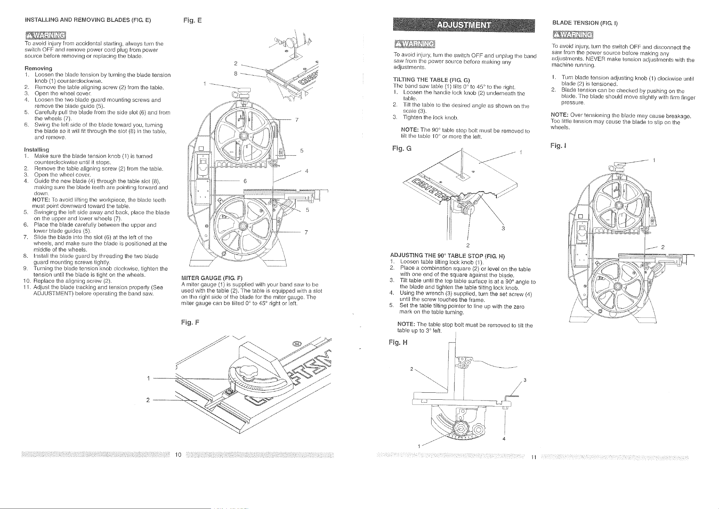
INSTALLINGANDREMOVINGBLADES(FIG.E)
Toavoidinjuryfromaccidentalstalling,alwaysturnthe
switchOFFandremovepowercordplugfrompower
soclrcebeforeremovingorreplacingtheblade.
Removing
1. Loosenthebladetensionbyturningthebladetension
knob(I) counterclockwise.
2. Removethetablealigningscrew(2)fromthetable.
3. Openthewheelcover.
4. Loosenthetwobladeguardmountingscrewsand
removethebladeguide(5).
5, CarefullypulltheMadefrom[hesideslot(6)andfrom
thewheels(7).
6. Swingtheleftsideof_hebladetowardyou,turning
thebladesoilwillfitthroughIheslot(8)inthetable,
andremove.
Installing
1. MakeSLUethebladetensionknob(1)isturned
counterclockwiseuntilitstops.
2. Removethetablealigningscrew(2)fromthetable.
3, Openthewheelcover.
4., Guidethenewblade(4)throughthetableslot(8),
makingsurethebladeteetharepointingforwardand
down.
NOTE:Toavoidliftingtheworkpiece,thebladeteeth
mustpointdownwardtowardthetable.
5. Swingingtheleftsideawayandback,placetheblade
ontheupperandlowerwheels(7),
6. Placethebladecarefullybetweentheupperand
lowerbladeguides(5),
7. Slidethebladeintothestot(6)attheleftofthe
wheels,andmakesurethebladeispositionedatthe
middleofthewheels,
8. Instal/thebladeguardbythreadingthetwoblade
guardmountingscrewstightly.
9. Turningthebladetensionknobclockwise,tighLenthe
tensionuntil[hebladeistightonthewheels.
10.Replacethealigningscrew(2).
11.Adjustthebladetrackingandtensionproperly(See
ADJUSTMENT)beforeoperatingthebandsaw.
Fig. E
MITER GAUGE (FIG. F)
A miter gauge (1) is supplied with your band saw to be
used with the table (2). The table is equipped with a slot
on the right side of the blade for the miter gauge, The
miter gauge can be tilted 0° to 45'* right or left.
To avoid injury, turn the switch OFF and unplug the band
saw from Ihe power source before making any
adjusImenls_
TILTING THE TABLE (FIG. G)
The band saw table (1} tit_s0'_to 45 ° to Ihe right
1. Loosen the handle lock knob (2) underneath fhe
lable,
2. Tilt the tabIe to the desired angle as shown on the
scale (3).
3. Tighten the tock knob.
NOTE: The 90" table stop bolt mLIS[ be removed to
tilt Ihe table 10° or more the left.
ADJUSTING THE 90 ° TABLE STOP (FIG. H)
1. Loosen table tilting lock knob (1).
2. Place a combination square (2) or level on the table
with one end of the square against the blade,
3, Tilt table until the top table surface is at a'90 ° angle to
the blade and tighten the table tilting lock knob.
4. Using the wrench (3) supplied, turn the set screw (4)
until the screw touches the frame.
5. Set the table tilting pointer to line up with the zero
mark on the table turning.
NOTE: The table stop bolt must be removed to tilt the
table up to 30 left.
Fig. H
I
/
!
\
: :::: : : :: :]: :::::: :: ;: :
BLADE TENSION (FIG. 1)
To avoid injury, turn the switch OFF and disconnect the
saw from the power source before making any
adjustmenls. NEVER make tension adjustments with the
machine running.
1, Turn blade tension adjusting knob (1) clockwise until
blade (2) is tensioned.
2. Blade tension can be checked by pushing on the
blade. The blade should move slighHy with firm finger
pressure.
NOTE: Over tensioning the blade may cause breakage.
Too Iittle tension may cause the blade to slip on the
wheels.
Fig. I
J 2
11 :: :::: :: :::: : :::;;::::
Loading ...
Loading ...
Loading ...