
CR/ F /'S
NUMBEI 917.257661
. Assembly
= Operation
- Customer Responsibilities
- Service and Adjustments
= Repair Parts
OWNER'S MANUAL
CAUTION: Read and follow all safety rules and instructions before operating this equipment.
IIIIIIIIIIIIIII IIIIIIIIIIIIIIIIIIII IHIIIIIIIIIIIIIIIIIIIIIIIIIIIIIIII II IIIIIIIIIIIII
SAFETY RULES
Safe Operation Practices for Ride-On Mowers
IMPORTANT: THIS CUTTING MACHINE IS CAPABLE OF AMPUTATING HANDS AND FEET AND THROWING OBJECTS.
FAILURE TO OBSERVE THE FOLLOWING SAFETY INSTRUCTIONS COULD RESULT IN SERIOUS INJURY OR DEATH.
L ,.GENERAL OPERATION
• Read, understand, and follow all instructions in the manual
and on the machine before starting
- Only allow responsible adults, who are familiar with the
instructions, to operate the machine
,, Clear the area of objects such as rocks, toys, wire, etc.,
which could be picked up and thrown by the blade
• Be sure the area isctearof other people before mowing. Stop
machine if anyone enters the area
° Never carry passengers
• Do not mow in reverse unlessabsolutely necessary Always
look down and behind before and while backing
• Be aware of the mower discharge direction and do not point
it at anyone Do not operate the mower without either the
entire grass catcher or the guard in place.
• Slow down before turning.
• Never leave a running machine unattended. Always turn off
blades, set paWing brake, stop engine, and remove keys
before dismounting°
• Turn off blades when not mowing.
- Stop engine before removing grass catcher or unclogging
chute,,
• Mow only in daylight or good artificial tighL
• Do not operate the machine while under the influence of
alcohol or drugs
• Watch for traffic when operating near or crossingroadways.
• Use extra care when loading or unloading the machine into
a trailer or truck
II. SLOPE OPERATION
Slopes are a major factor related to ioss,_of.oontroi and tipover
accidents, which can result in severe injury or death. All slopes
require extra caution. Ifyou cannot back up the slopeorif you feel
uneasy on it, do not mow iL
DO:
• Mow up and down slopes, not across°
• Remove obstacles such as rocks, trc_ timt:s, etc.
° Watch for holes, ruts, or bumps. Uneven terrain could
overturn the machine. Tail grass can hide obstac/es.
• Use stow speed° Choose a lowgear so that you will not have
to stop or shift while on the slope.
• Follow the manufacturer's recommendations for wheel
weights or counterweights to improve stability_
• Use extra care with grass catchers or other attachments°
These can change the stabilityof the machine°
• Keep all movement on the slopes slow and gradual. Do not
make sudden changes in speed or direction.
=,.... Avoid starting or stopping on a slop.e if tires lose traction,
disengage the blades and proceed slowly straight down the
slope
DO NOT:
o Donottumons!opesunlessnecessary, andthen,tumslowty
and gradually downhill, if possible
• Do not mow near drop oils, ditches, or embankTnents. The
mower €ould suddenly turnover if a wheel is over the edge
of a cliff or ditch, or if an edge caves in.
. Do not mow on wet grass. Reduced traction could cause
sliding.
• Do not try to stabilize the machine by putting yourfoot on the
ground.
• Do not use grass catcher on steep slopes.
IlL CHILDREN
Tragic accidents can occur if the operator [s not alert to the
presence of children. Children are often attracted to the machine
and the mowing activity Never assume that children will remain
where you last saw them
° Keep children outof the mowing area and under the watchful
care of another responsible adulL
• Be alert and turn machine off if children enter the area,
° Before and when backing, look behind and down for small
children°
. Never carry children They may fall off and be seriously
injured or interfere with safe machine operation
- Never allow children to operate the machine
° Use extra care when approaching blind comers, shrubs,
trees, or other objects that may obscure vision.
IV. SERVICE
° Use extracare inhandlinggasoIine and other fuels. They are
flammable and vapors are exptosiveo
Use only an approved container
Never remove gas cap or add fuel with the engine
running. Allow engine to cool before refueling. Do not
smoke.
- Never refuel the machine indoors
Never store the machine or fuel container inside where
there is an open flame, such as a water heater.
° Never run a machine inside a closed area.
• Keep nuts and belts, especially blade attachment bolts, tight
and keep equipment in good cond_on.
• Never tamper with safety devices. Check their proper
operation regularly
- Keep machine free of grass, teaves, or other debris build-up
Clean oil or fuel spillage Allow machine to cool before
storing.
° Stop and inspect the equipment if you strike an object.
Repair, if necessary, before restarting.
° Never make adjustments or repairs with the engine running.
• Grass catchercomponents aresubject to wear, damage, and
deterioration, which could expose moving parts or allow
objects to be thrown. Frequently check components and
replace with manufacturer's recommended parts, when nec-
essary..
• Mower blades are sharp and can cut. Wrap the blade(s) or
wear gloves, and use extra caution when servicing them.
- Check brake operation frequently. Adjust and service as
required.
J tj_ L.ook for this symbol to point out [mpor- I
tant safety precautions. It means J
CAUTION!!! BECOME ALERT_.!! YOUR J
SAFETY iS INVOLVED. J
IIIIIII II II I IllU III IJlllll III IIIII
CAUTION: Always disconnect spark
plug wire and place wire where it cannot
contact spark plug in order to prevent
accidental starting when setting up,
transporting, adjusting or making
repa,rs.
L I IIU LI I IILIIIILIIIII : Illl II _ J_lll
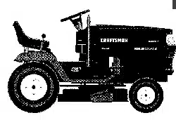
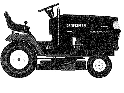
CONGRATULATIONS on your purchase of a Sears
tractor. It has been designed, engineered and manufac-
tured to give you the best possible dependability and
pedormance.
Should you experienceany problem you cannoteasily
remedy, please contact your nearest Sears Service Cen-
ter/Department. We have competent, well-trained tech-
nicians and the proper tools to service or repair this unit.
Piease read and retain this manual. The ins|_ctions will
enable you to assemble and maintain your unit properly,.
Always observe the "SAFETY RULES"°
MODEL
NUMBER
SERIAL
NUMBER
917o257661
DATE OF PURCHASE
THE MODELAND SERIAL NUMBERSWlLL BE FOUND
ON A PLATE UNDER THE SEAT.
YOU SHOULD RECORD BOTH SERIAL NUMBERAND
DATE OF PURCHASE AND KEEP IN A SAFE PLACE
FOR FUTURE REFERENCE.
MAINTENANCE AGREEMENT
A Sears maintenance agreement is available on this prod-
uct. Contact your nearest Sears store for details.
CUSTOMER RESPONSIBILITIES
. Read and observe the safety rules.
. Followaregularschedulein maintaining, caring forand
using your unit.
,, Follow the instructions under "Customer Responsibili-
ties" and "Storage" sections of this owner's manual.
................. _..................... ,, ,,, _ Ullllll i ,11 iiiii i ii i i
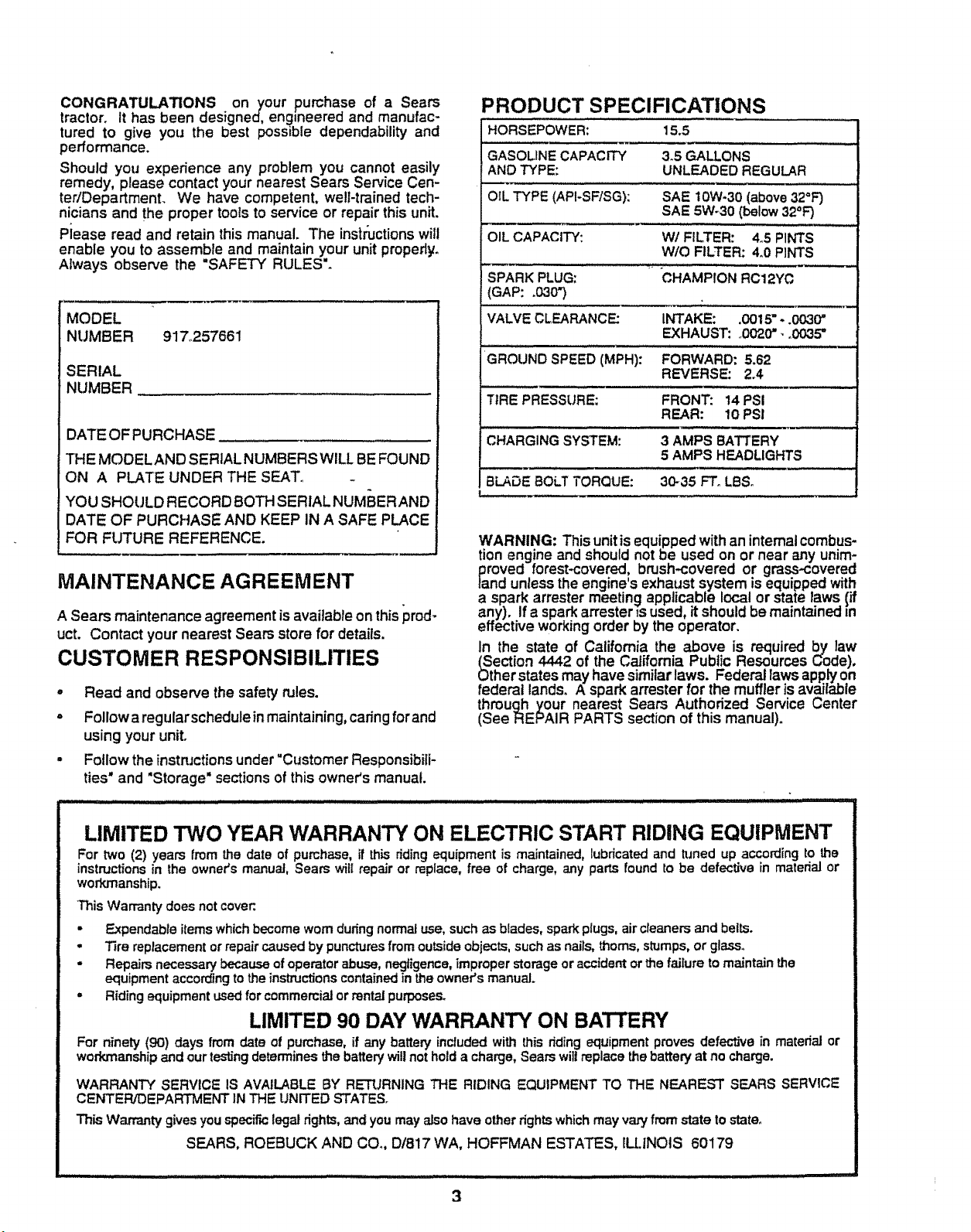
PRODUCT SPECIFICATIONS
HORSEPOWER; 15.5
GASOLINE CAPACITY 3.5 GALLONS
AND TYPE: UNLEADED REGULAR
OIL TYPE (API-SF/SG): SAE I 0W.30 (above 32"F)
SAE 5W_30 (below 32=F)
OIL CAPACITY: W/FILTER: 4.5 PINTS
W/O FILTER: 4.0 PINTS
SPARK PLUG: CHAMPION RC12YC
(GAP; .030_)
"vALVE CLEARANCE: INTAKE: .0015"..003(Y'
EXHAUST: ,0020". o0035"
GROUND SPEED (MPH): FORWARD; 5.62
REVERSE: 2.4
!
TIRE PRESSURE: FRONT: 14 PSI
REAR: 10 PSi
:
CHARGING SYSTEM: 3 AMPS BATTERY
5 AMPS HEADLIGHTS
BLADE BOLT TORQUE: 30-35 FTo LBSo
WARNING: This unit is equipped with an internalcombus-
tion engine and should not be used on or near any unim-
proved forest-covered, brush-covered or grass.covered
land unless the engine's exhaust system is equipped with
a spark arrester meeting applicable local or state taws {if
any). If a spark an'ester _sused, it snould be maintained =n
effective working order by the operator.
In the state of California the above is required by law
(Section 4442 of the California Public Resources Code),
Other states may have similar laWS. Federal laws app_ on
federal lands. A spark arrester for the muffler is available
through your nearest Sears Authorized Service Center
(See REPAIR PARTS section of this manual).
LIMITED TWO YEAR WARRANTY ON ELECTRIC START RIDING EQUIPMENT
For two (2) years from the date of purchase, if this ridingequipment is maintained, lubricated and tuned up according to the
instructions in the owner's manual, Sears ,,viiirepair or replace, free of charge, any parts found to be defective in matedal or
workmanship.
This Warranty does not cover:.
• Expendable items which become worn during normal use, such as blades, spark plugs, air cleaners and belts.
• Tire replacement or repair caused by punctures from outside objects, such as nails, thorns, stumps, or glass.
• Repairs necessary because of operator abuse, negfigence, Tmproper storage or accident or the failure to maintain the
equipment according to the instructionscontained in the owner's manual.
, Riding equipment used for commercial or rental purposes.
LIMITED 90 DAY WARRANTY ON BATTERY
For ninety (90) days from date of purchase, if any battery inctuded with this riding equipment proves defective in material or
workmanship and our testingdetermines the battery will not hold a charge, Sears will replace the battery at no charge.
WARRANTY SERVICE IS AVAILABLE BY RET1JRNING THE RIDING EQUIPMENT TO THE NEAREST SEARS SERVICE
CENTER/DEPARTMENT 1NTHE UNITED STATES.
This Warranty gives youspec_,clegal rights,andyoumay also have otherrights whichmay va_,from state tostate°
SEARS, ROEBUCK AND CO. D/817 WA, HOFFMAN ESTATES, ILLINOIS 60179
3
S AF_-TY RULES ........................................................... 2
PRODUCT SPECIRCATIONS ...................................... 3
CUSTOMER RESPONSIBILITIES ..................... 3, 16-19
WARRANTY ..: ................................................. ;. ........... 3
TRACTOR ACCESSORIES ........................... ._........... ;. 5
ASSEMBLY ............................................................. 7-10
OPERATION ......................................................... 11-15
MAII'_ENANCE SCHEDULE ..................................... 16
SERVICE AND ADJUSTMENTS ........................... 20-26
STORAGE ................................................................... 27
TROUBLESHOOTING .......................................... 26-29
REPAIR PARTS - TRACTOR ....... ;...................... 32-47
REPAIR PARTS - ENGINE ............. +.................... 50-55
PARTS ORDERING/SERVICE ............... BACK COVER
INDEX
A
Accessories ........................................... 5
Adjustments:
Brake ............................................ 22
Carburetor .................................... 26
Mower
Front-To-Back ......................... 21
Side-To-Side ............................ 21
Throttle Control Cable .................. 26
Air Filter, Engine ...................................... 19
Ait Screen, Engine ..................................18
Assembly ............................................. 7-10
B
Battery,_,
Charging .......................................... 8
Cleaning ....................................... t7
installation ...................................... 9
Levels .......................................... 8,17
Preparation .................................... 8
Starting with Weak Battery .......... 24
Storage ......................................... 27
Terminals ..................................... 17
Bell:
Motion Drive
Removal/Replacement ............ 23
Mower Belt(s)
Removal/Replacement ............. 22
Blade:
Sharpening .................................... 17
Replacement ................................ 17
Brake Adjustment ................... ............... 22
C
Carburetor Adjustment ........................ 26
Controls, Tractor .................................. 11
Customer Responsibilities.................16-19
Engine:
Air Filter..................................... 19
Air Screen .................................. 18
Cooling Fins ............................. 19
Engine Oil ........................... 13,18
Fuel Filter .................................. 19
Spark Plug(s) ........................... 19
Tractor:.
Battery ...................................... 17
Blade ......................................... 17
Lubncation Chart ....................... 16
Maintenance Schedule ............ 16
Tire Care .......................... 8,t7,27
Transmde ................................. 18
Cuffing Height, Mower ......................... 12
E
Electrical:
tntedocks and Relays ................... 25
Schematic .................................... 31
Wiring Diagram ............................ 32
Engine:
Air Filter......................................... 19
Air Screen ..................................... 18
Cooling Fins .................................. 19
Oil Change ................................... 18
Oil Level ........................................ t8
Oil Type ................................... 13,18
Preparation .................................. 13
Repair Parts ............................ 50-55
Starting ........................................... 14
Storage ........................................... 27
F
Filter:.
Air Filter.......................................... t9
Fuel ............................................... 19
Fuel:
Type ............................................. 14
Storage ........................................ 27
Fuse ....................................................... 25
H
Hood Removal_/InstaUation................... 25
L
Leveling Mower Deck ......................... 21
Lubrication:
Chart ............................................ 16
Engine .......................................... t8
M
Maintenance Schedule ........................ t6
Mower:
Adjustment, Front-to-Back ............. 21
Adjustment, Side.to-Side .............. 21
Blade Replacement ....................... 17
Blade Sharpening ........................ 17
Cutting Height .............................. 12
Installation .................................... 20
Operation ....................................... 13
Removal ....................................... 20
Mowing TTps........................................ 15
Muffler ................................................. 19
Spark Arraster ........................... 3,40
O
Oil:
Cold Weather Conditions ........ 12,18
Engine ......................................... 18
Storage ........................................ 27
Operation ....................................... 1 1-15
Operating Mower ................................. 13
Options:
Accessories .................................... 5
Spark An*ester............................. 3,40
P
Parking Brake ................................ 11-12
Parts Bag .................. :........................... 6
Parts, Reptacement/RP.pair ............ 32-47
Product Specirmations........................... 3
R
Repair Parts ................................... 32-47
S
Safety Rules .......................................... 2
Seat ....................................................... 8
Service and Adjustments ............... 20-26
Carburetor ..................................... 26
Pus++............................................. 25
Hood RemovaLflnstaJlation........... 25
Motion Drive Belt
Removal/Replacement ............ 23
Mower Belt(s)
Removal/Replacement ............ 22
Mower Adjustment
Front-to-Back .......................... 21
Side-to-Side ............................ 21
Mower Remova_nstaJlation ......... 20
13re Care ............................... 8,17,27
Slope Guide Sheet .............................. 59
Spark Plug(s) ........................................ 19
Specifications ......................................... 3
Sta_ng the Engine ............................. 14
Steering Wheel .................................. 7,24
Stopping the Tractor ............................ 12
Storage ................................................ 27
T
Throttle Control Cable Adjustment ...... 26
Tires............................................ 8,17,27
Trouble Shooting Chart .................. 28-29
Transaxle ............................................ 18
4
W
Warranty ................................................. 3
Wiring Oiagram ................................... 32
Wiring Schematfc ............................... 31
i,ii, ,, i,i .......... ill ll.... i,,_ •
ACCESSORIES AND ATTACHMENTS
,m,,, H ..................................... III " III L' _
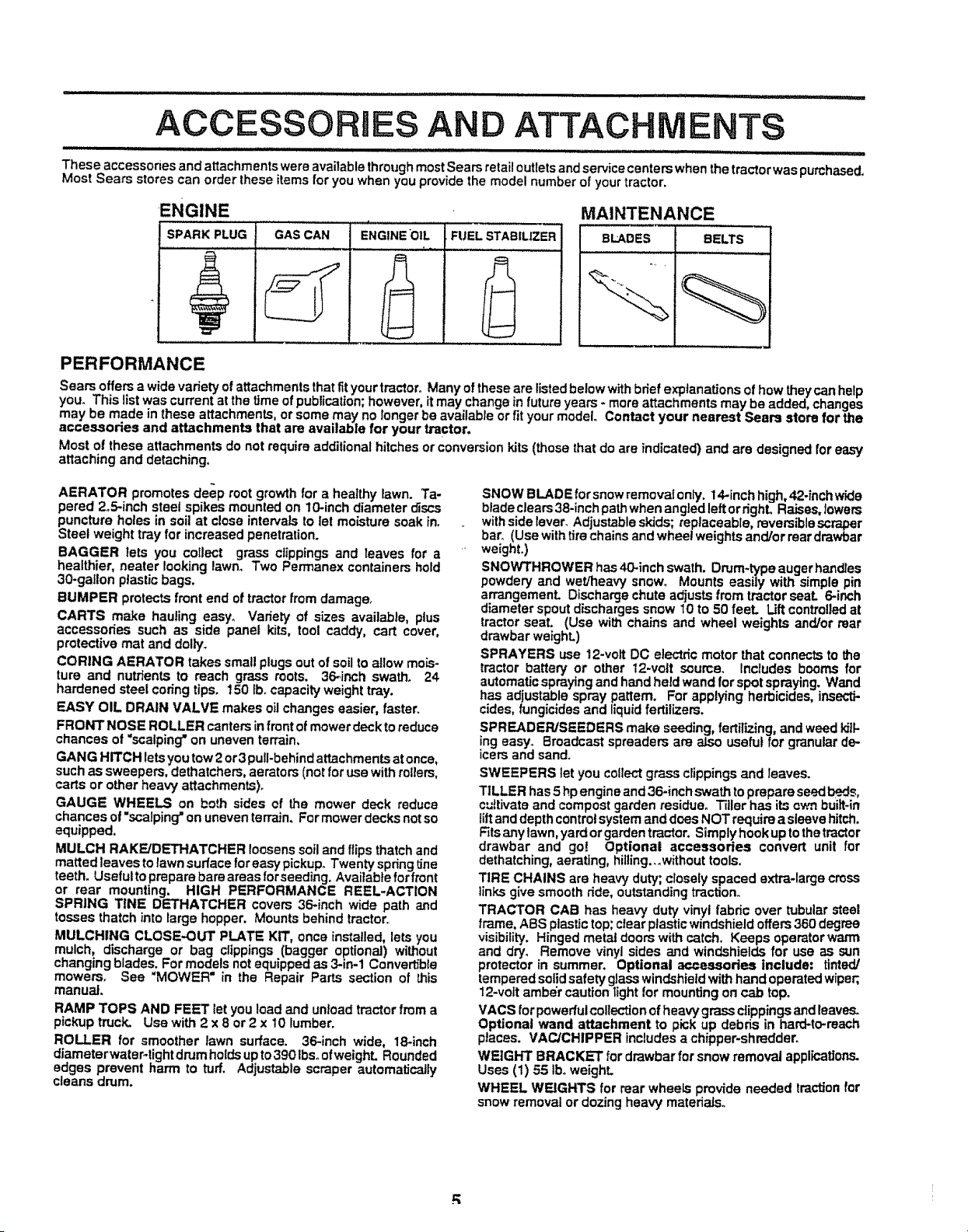
These accessories and attachments were available throughmost Sears retail outlets and service centers when the tractor was putchased_
Most Sears stores can order these items for you when you provide the model number of your tractor.
ENGINE
SPARK PLUG GAS CAN ENGINE*OIL FUEL STABlUZER
MAINTENANCE
BLADES BELTS
PERFORMANCE
Sears offers a wide variety of attachments that fit your tractor° Many of these are listed below with brief explanations of how they can help
you. This list was current at the time of publication; however, it may change in future years - more attachments may be added, changes
may be made in these attachments, or some may no longer be available or fit your model. Contact your nearest Sears store for the
accessories and attachments that are available for your tractor.
Most of these attachments do not require additional hitches or conversion kits (those that do are indicated) and are designed for easy
attaching and detaching,
AERATOR promotes deep root growth for a healthy lawn. Ta-
pered 2o5-inch steel spikes mounted on 10-inch diameter discs
puncture holes in soil at close intervals to let moisture soak in.
Steel weight tray for increased penetration.
BAGGER lets you collect grass clippings and leaves for a
healthier, nearer looking lawno Two Permanex containers hold
30-gallon plastic bags.
BUMPER protects front end of tractor from damage_
CARTS make hauling easy° Variety of sizes available, plus
accessories such as side panel kits, tool caddy, cart cover,
protective mat and dolly_
CORING AERATOR takes small plugs out of soil to allow mois-
ture and nutrients to reach grass roots. 36_inch swath. 24
hardened steel coring tips. 150 lbocapacity weight tray.
EASY OIL DRAIN VALVE makes oil changes easier, faster
FRONT NOSE ROLLER canters in front of mower deck to reduce
chances of "scalping"on uneven terrain,
GANG HITCH lets you tow 2 or 3 pull-behindattachments atonce,
such as sweepers, dethatchers, aerators (not for use with rollers,
carts or other heavy attachments).
GAUGE WHEELS on both sides of the mower deck reduce
chances of "scalping"on uneven terrain. For mower decks notso
equipped,
MULCH RAKEiDETHATCHER loosenssoil and ftips thatch and
matted leaves to lawn surface for easy pickup° Twenty springline
teeth. Usefuttoprepare bare areas forseeding. Available for front
or rear mounting. HIGH PERFORMANCE REEL-ACTION
SPRING TINE DETHATCHER covers 36-inch wide path and
tosses thatch into large hopper. Mounts behind tractor
MULCHING CLOSE.OUT PLATE KIT, once installed, lets you
mulch, discharge or bag clippings (bagger optional) without
changing blades. For models not equipped as 3-in.1 Convertible
mowers. See "MOWER" in the Repair Parts section of this
manual.
RAMP TOPS AND FEET let you load and unload tractor from a
pickup truck_ Use with 2 x 8 or 2 x 10 lumber.
ROLLER for smoother lawn surface. 36-inch wide, 18-inch
diameterwateF-tight drumholdsup to390 Ibs. ofweighL Rounded
edges prevent harm to turf. Adjustable scraper automatically
cleans drum.
SNOW BLADE for snow removal only. 14-inch high, 42-inch wide
blade clears38-inch path when angled left or dghL Raises, lowers
with side lever. Adjustable skids; replaceable, reversible scraper
bar. (Use with tirechains and wheel weights and/or reardrawbar
weight.)
SNOWTHROWER has 40.inch swath. Drum-type auger handles
powdery and wet/heavy snow° Mounts easily with simple pin
arrangement. Discharge chute adiusts from tractor seal 6-inch
diameter spout discharges snow 10 to 50 feeL Lift controlled at
tractor seat. (Use with chains and wheel weights and/or rear
drawbar weight.)
SPRAYERS use 12-volt DC electric motor that connects to the
tractor battery or other 12-vott source. Includes booms for
automatic spraying and hand held wand for spot spraying. Wand
has adjustable spray pattern. For applying herbicides, insecti-
cides, fungicides and liquidfertilizers.
SPREADER/SEEDERS make seeding, fertilizing, and weed kiik
!ng easy. Broadcast spreaders are also useful for granular de..
=cers and sand°
SWEEPERS tet you collect grass clippings and leaves.
TILLER has 5 hp engine and 36-inch swath to prepare seedbeds,
cultivate and compost garden residue° Tiller has its own built.in
lilt and depth controlsystem and does NOT require a sleeve hitch,
Fitsany tawn, yard or garden tractor, Simplyhook up to the tractor
drawbar and go! Optional accessories convert unit for
dethatching, aerating, hilling...without tools.
TIRE CHAINS are heavy duty; closely spaced extra-large cross
links give smooth ride, outstanding traction.
TRACTOR CAB has heavy duty vinyl fabric over tubular steel
frame, ABS ptastictop; clear plastic windshield offers 360 degree
visibility. Hinged metal doors with catch. Keeps operator warm
and dry. Remove vinyl sides and windshields for use as sun
protector in summer. Optional accessories include; tinted/
tempered solid safety glass windshieldwith hand operated wiper;,
12-volt amber caution light for mounting on cab top.
VACS for powerfulcollection of heavy grass clippings and leaves.
Optional wand attachment to pick up debris in hard-to-reach
places. VACJCHIPPER includes a chipper-shredder.
WEIGHT BRACKET for drawbar for snow removal applications.
Uses (1) 55 tbo weight.
WHEEL WEIGHTS for rear wheels provide needed traction for
snow removal or dozing heavy materials.
" .......................................................... Hill, ii ill, i,H_
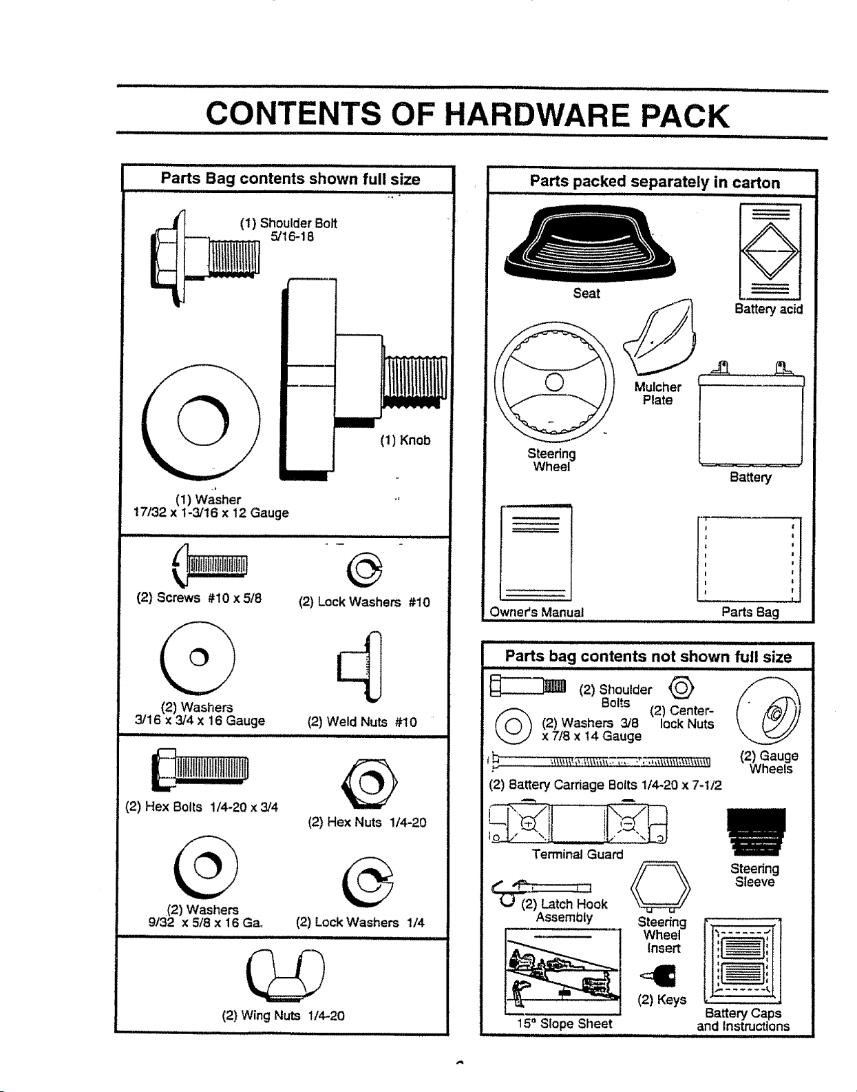
CONTENTS OF HARDWARE PACK
Parts Bag contents shown full size
(1) Shoulder Bolt
5/16-18
_--]
i
(1) Knob
Illlll
(1) Washer
17/32 x 1-3/16 x 12 Gauge
(2) Screws #10 x 5/8
(2) Washers
3/16 x 3/4 X 16 Gauge
@
(2) Lock Washers #10
(2) Weld Nuts #10
i!illtlllllfltlllllltltlln
(2) Hex Bolts 1/4-20 x 3/4
,(2) Washers
9/32 x 5/8 x 16 Ga.
(2) Hex Nuts 1/4-20
(2) Lock Washers 1/4
(2) Wing Nuts 1/4--20
lllll i i
Parts packed separately in carton
ill iii mll,llllll,
Seat
i,ii iii i i
Battery acid
f.
Mulcher t
Plate
Steering
Wheel _ '
Battery
Owner's Manual
J'i
J
Parts Bag
Parts bag contents not shown full size
(2)ShoulderQ @
Bolts (2) Center-
(_ (2) Washers 3/8 lock Nuts
x 7/8 x t4 Gauge
. Wheels
(2) Battery Carnage Bolts 1/4-20 x 7-1/2
_I !!.:."_:,t_oJ
Terminal Guard
(_ (2) Latch Hook
Assembly
15 ° Slope Sheet
Steer{ng
Wheel
Insert
(2) Keys
Steering
Sleeve
It':,...... fl,,
Battery Caps
and instructions
LY
:7 II'MII I1'1' I L I'1 ,i, ,,_1,,i, i
Your new tractor has been assembled at the factory with exception of those parts left unassembled for shipping purposes.
To ensure safe and proper operation of your tractor, all parts and hardware you assemble must be tightened securely° Use
the correct tools as necessary to insure proper tightness.
TOOLS REQUIRED FOR AssEMBLY
A socket wrench set will make assembly easier. Standard
wrench sizes are listed,
(1) 9/16 "_wrench (2) 7/16" wrench
(1) 1/2= wrench (1) 314" socketw/drive
Utility knife ratchet
Tire pressure gauge (1) Phillips Screwdriver
When right and left hand is mentioned in this manual, it
means when you are in the operating position (seated
behind the steering wheel).
TO REMOVE TRACTOR FROM CAR-
TON
UNPACK CARTON
- Remove all accessible loose parts and parts cartons
from carton (See page 6).
. Cut, from top to bottom, along lines on all four comers
of carton, and lay panels flat,
o Check for any additional loose parts or cartons and
remove.
BEFORE ROLLING TRACTOR OFF SKID
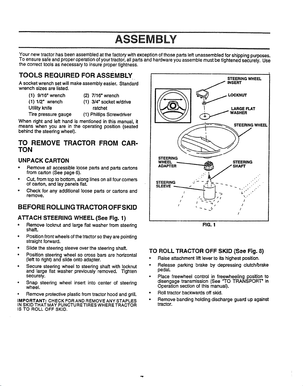
ATTACH STEERING WHEEL (See Fig. 1)
° Remove Iocknut and large flat washer from steering
shaft.
o Position front wheels of the tractor so they are pointing
straight forward.
° Slide the steering sleeve over the steedng shaft.
- Position steering wheel so cross bars are horizontal
(left to right) and slide onto adapter.
- Secure steedng wheel to steering shaft with locknut
and large flat washer previously removed. Tighten
securely.
o Snap steering wheel insert into center of steering
wheel.
° Remove protective plastic from tractor hood and grill.
IMPORTANT: CHECK FOR AND REMOVE ANY STAPLES
IN SKID THAT MAY PUNCTURETIRES WHERE TRACTOR
IS TO ROLL OFF SKID_
STEERING WHE_
1 LARGEFLAT
,_,_ WASHER
STEERING WHEEL
STEERING
WHEEL STEERING
/ I ~%_/ / f
I ,_ .,' t
/
RG. 1
TO ROLL TRACTOR OFF SKID {See Fig. 8)
° Raise attachment lift lever to its highest position.
o Release parking brake by depressing clutch/brake
pedal.
• Place freewhee! control in freewheeling position to
disengage transmission (See "TO TRANSPORT = in
Operation section of this manual).
° Rolltractor backwards off skid,
• Remove banding holding discharge guard up against
tractor.
LY
HOW TO SET UP YOUR TRACTOR
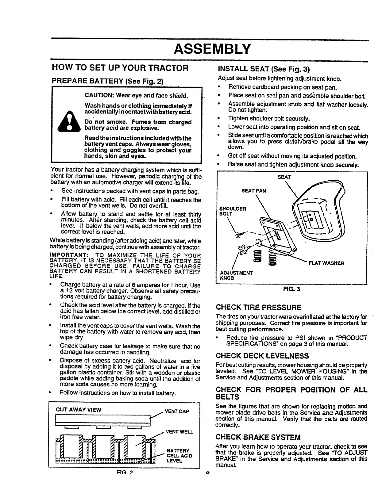
PREPARE BATTERY (See Fig. 2)
CAUTION: Wear eye and face shield.
Wash hands or clothing immediately if
accidentally in contact with battery acid,
Do"not smoke, Fumes from charged
battery acid are explosive,
Read the instructions included with the
battery vent caps, Always wear gloves,
clothing and goggles to protect your
hands, skin and eyes.
IIII iiiiiiii I L I UII !UII I I iiii iiiii i I
Your tractor has a battery charging system which is suffi-
cient for normal use. However, periodic charging of the
batter,,/with an automotive charger wilt extend ffs life.
• See instpJctionspacked with vent caps in parts bag.
• Fill batter,! with acid° Fill each cell untilit reaches the
bottom of the vent wells. Do not overt'ilL
• Allow battery to stand and settle for at least thirty
minutes° After standing, check the battery cell acid
level. If below the vent wells, add more acid until the
correct level is reached.
While battery is standing (after adding acid) and later, while
battery is being charged, continuewith assembly of tractor,
IMPORTANT: TO MAXIMIZE THE LIFE OF YOUR
BATTERY, tT IS NECESSARY THAT THE BATTERY BE
CHARGED BEFORE USE,= FAILURE TO CHARGE
BATTERY CAN RESULT tN A SHORTENED BATTERY
LIFE,
° Charge batter,/at a rate of 6 amperes for i hour_Use
a 12 volt battery charger. Observe all safety precau-
tions required for battery charging.
° Check the acid level after the battery ischarged, if the
acid has fallen below the correct level, add distilled or
iron free water.
° Install the vent caps to cover the vent wells. Wash the
top of the battery with water to remove any acid, then
wipe dry.
- Check battery case for leakage to make sure that no
damage has occurred in handling.
• Dispose of excess battery acid. Neutralize acid for
disposal by adding it to two gallons of water in a five
gallon plastic container. Stir with a wooden or plastic
paddle while adding baking soda until the addition of
more soda causes no more foaming.
• Follow instructions on how to install battery,
CUT AWAY VIEW VENT CAP
VENTWELL
BATTERY
CELL ACiD
LEVEL
=,Hm,, = ..................................... !,!! ! .... i I I II !! IIl_L'll , , ...........
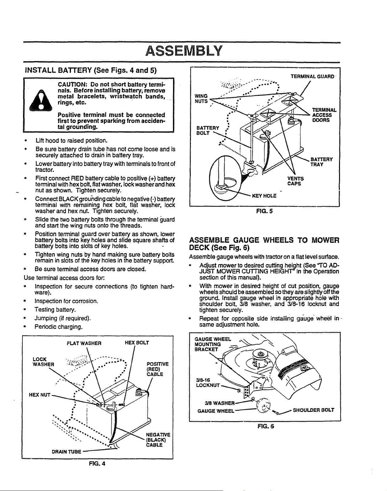
INSTALL SEAT (See Fig. 3)
Adjust seat before tightening adjustment knob.
= Remove cardboard packing on seat pan.
. Place seat on seat pan and assemble shoulderbolt.
o Assemble adjustment knob and flat washer loosely.
Do not tighten.
° T_ghtenshoulder bolt securely.
• Lower seat into operating position and sit on seal
= Slide seat untila comfortable positionis reachedwhk:h
allows you to press clutch/brake pedal all the way
down.
. Get off seat withoutmoving its adjusted position.
° Raise seat and tighten adjustment knob securely°
i
SEAT
SEAT PAN
SHOULDER
BOLT
ADJUSTMENT
KNOB
FIG. 3
FLAT WASHER
CHECK TIRE PRESSURE
The tires on your tractor were overinflated at the factory for ....
shipping purposes. Correct tire pressure is important for
best cuttingperformance.
• Reduce tire pressure to PSI shown in "PRODUCT
SPECIFICATIONS on page 3 of this manual.
CHECK DECK LEVELNESS
For best cutting results, mower housing should be pmpedy
leveled. See "TO LEVEL MOWER HOUSING" in the
Service and Adjustments section of this manual.
CHECK FOR PROPER POSITION OF ALL
BELTS
See the figures that are shown for replacing motion and
mower blade drive belts in the Service and Adjustments
section of this manual. Verify that the belts are muted
correctly.
CHECK BRAKE SYSTEM
After you learn how to operate your tractor, check to see
that the brake is propedy adjusted. See "TO ADJUST
BRAKE" in the Service and Adjustments section of this
manual.
_ _ o
........................ i, ii II_IL I n : I I,,lll,lll,I,I, ,,,I ,//11 I.......................
ASSEMBLY
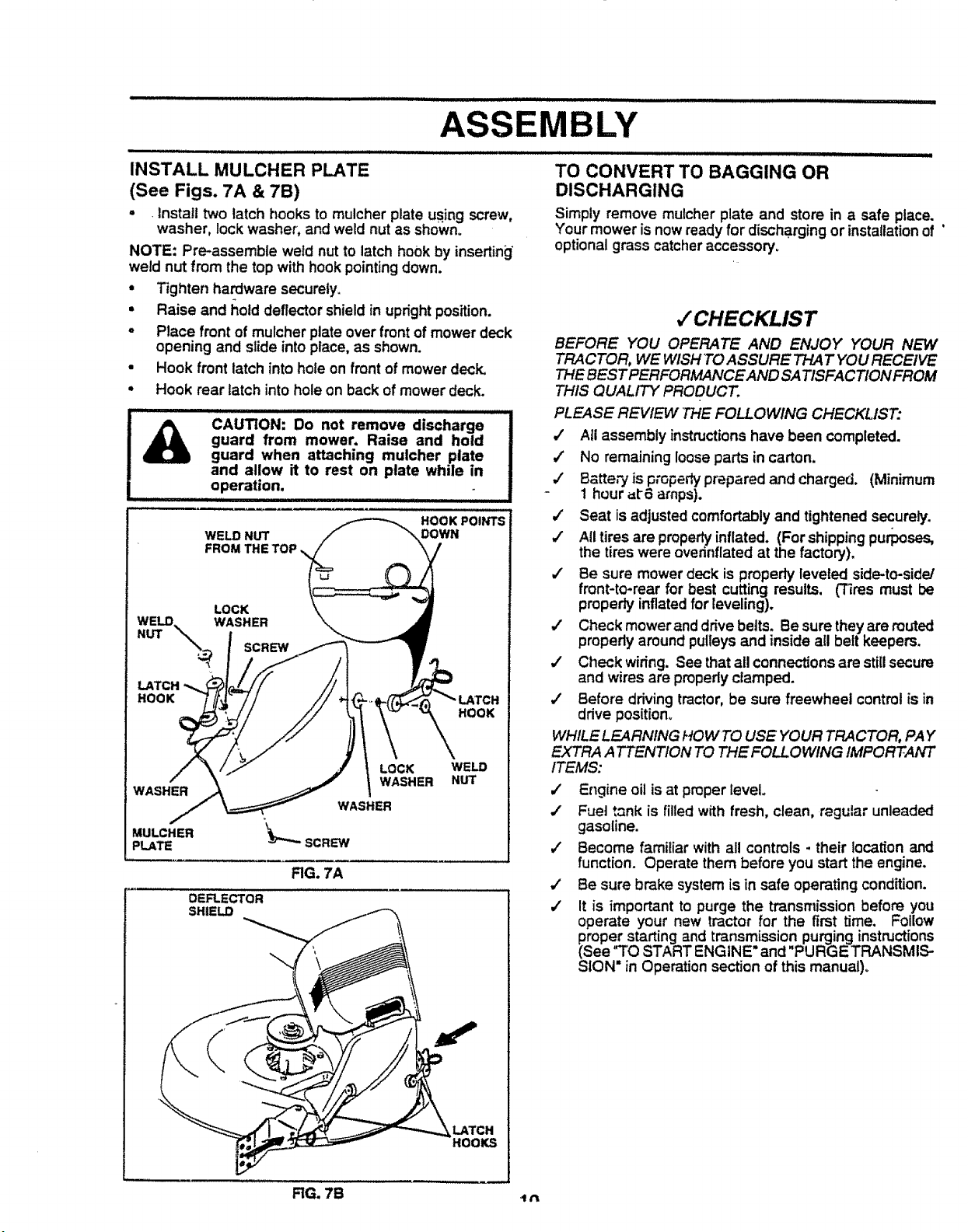
INSTALL BATTERY (See Figs. 4 and 5)
CAUTION: Do not short battery termi-
nals. Before installin_l battery; remove
metal bracelets, wristwatch bands, ....
rings, etc.
Positive terminal must be connected
first to prevent sparking from acciden-
tal grounding.
i iiii1,,, !
, Lift hood to raised position,
° Be sure battery drain tube has not come loose and is
securely attached to drain in battery tray.
° Lower battery into battery tray with terminalstofront of
tractor.
- Firstconnect RED battery cable to positive(+) battery
terminalwith hex bolt, fiatwasher, lock washerand hex
nut as shown. Tighten securely.
• Connect BLACK groundingcable tonegative (_ battery
terminal with remaining hex bolt, fiat washer, lock
washer and hex nut. Tighten securely.
° Slide the two battery bolts through the terminal guaKI
and start the wing nuts onto the threads.
o Position terminal guard over battery as shown, lower
battery bolts into key holes and slide square shafts of
battery bolts into slotsof key holes.
° T_ghtenwing nuts by hand making sure battery bolts
remain in slots of the key holes in the battery support.
,' Be sure terminal access doors are closed.
Use terminal access doors for:.
° Inspection for secure connections (to tighten hard-
ware).
° Inspection for corrosion.
° Testing battery.
° Jumping (if required),
- Periodic charging.
FLAT WASHER HEX BOLT
LOCK i: ....
WASHER POSITIVE
,"" * CABLE
Ha
•
it
NEGATIVE
(BLACK)
CABLE
DRAIN TUBE
WING
NUTS
BATTERY
BOLT
TERMINAL GUARD-
TERMINAL
: ACCESS
DOORS
HOLE
VENTS
CAPS
BATTERY
TRAY
FIG. 5
ASSEMBLE GAUGE WHEELS TO MOWER
DECK (See Fig. 6)
Assemble gauge wheels withtractor ona fiat levelsurface°
° Adjust mower to desired cuttingheight (See "TO AD-
JUST MOWER CUTTING HEIGHT" in the Operation
section of this manual).
° With mower in desired height of cut position, gauge
wheels shouldbe assembled so they are slightlyoffthe
ground. Install gauge wheel in appropriate hole wP,_h
shoulder bolt, 3/8 washer, and 3/8-16 Iocknut and
tighten securely.
• Repeat for opposite side instaiiing gauge_wheel in-
same adjustment hole.
GAUGE WHEEL
MOUNTING
BRACKET
3/8-16
SHOULDER BOLT
RG. 6
RG. 4
iiil_ ....
ASSEMBLY .................
,,,,,,, ,, ,,,, ,,,,, ,,,
INSTALL MULCHER PLATE
(See Figs. 7A & 7B)
• rInstall two latch hooks to mulcher plate using screw,
washer, lock washer, and weld nut as shown.
NOTE: Pre-assemble weld nut to latch hook by inserting]"
weld nut from the top with hook pointing down.
• Tighten hardware securely_
• Raise and I_otddeflector shield in upright position.
o Place front of mulcher plate over front of mower deck
opening and slide into place, as shown.
• Hook front latch into hole on front of mower deck.
• Hook rear latch into hole on back of mower deck.
CAUTION: Do not remove discharge !
guard from mower, Raise and hold
!
guard when attaching mulcher plate
and allow it to rest on plate while in
............OPeration.
HOOK POINTS
WELD NUT DOWN
FRO_,
HOOK
LATCH
HOOK
LOCK WELD
WASHER NUT
DEFLECTOR
SHIELD
FIG. 7A
_LATCH
HOOKS
WASHER
MULCHER
PLATE
" " ........................................................................ iiii ii ii
TO CONVERT TO BAGGING OR
DISCHARGING
Simply remove mulcher plate and store in a safe ptace.
Your mower is now ready for discharging or installation of '
optional grass catcheraccessory.
v"CHECKLIST
BEFORE YOU OPERATE AND ENJOY YOUR NEW
TRACTOR, WE WISH TO ASSURE THAT YOU RECEIVE
THE BEST PERFORMANCE AND SATISFACTION FROM
THIS QUALITY PRODUCT.
PLEASE REVIEW THE FOLLOWING CHECKLIST:
,/ Atl assembly instructionshave been completed.
,/ No remaining loose parts in carton.
/ Batte,'y is propedyprepared and charged. (Minimum
1 hour =t-6 amps).
J Seat is adjusted comfortably and tightened securely.
4" All tires are properlyinflated. (For shipping purposes,
the tires were overinfiated at the factory).
/ Be sure mower deck is properly leveled side-to-side/
front-to-rear for best cutting results. ('Fires must be
properly inflatedfor leveling).
,/ Check mowerand dnve belts. Be sure they are routed
propedy around pulleys and inside all belt keepers.
,/ Check wiring. See that all connections are stillsecure
and wires are properly clamped.
,/ Before driving tractor, be sure freewheel control is in
drive position.
WHILE LEARN/NG HOW TO USE YOUR TRACTOR, PAY
EXTRA A TTENT/ON TO THE FOLLOWING IMPORTANT
ITEMS:
,/ Engine oil is at proper level.
•f Fuel tank is filled with fresh, clean, regular unleaded
gasoline.
,/ Become familiar with all controls - their location and
function. Operate them before you start the engine.
•/ Be sure brake system is in safe operating condition.
/ It is important to purge the transmission before you
operate your new tractor for the first time. Follow
proper starting and transmission purging instructions
(See"TO START ENGINE and "PURGETRANSMIS-
SION" in Operation section of this manual)°
RG. 7B t n
OPERATION
,_riH i i/,ull,J i ,, = i i.ill,ll, i ,l=,
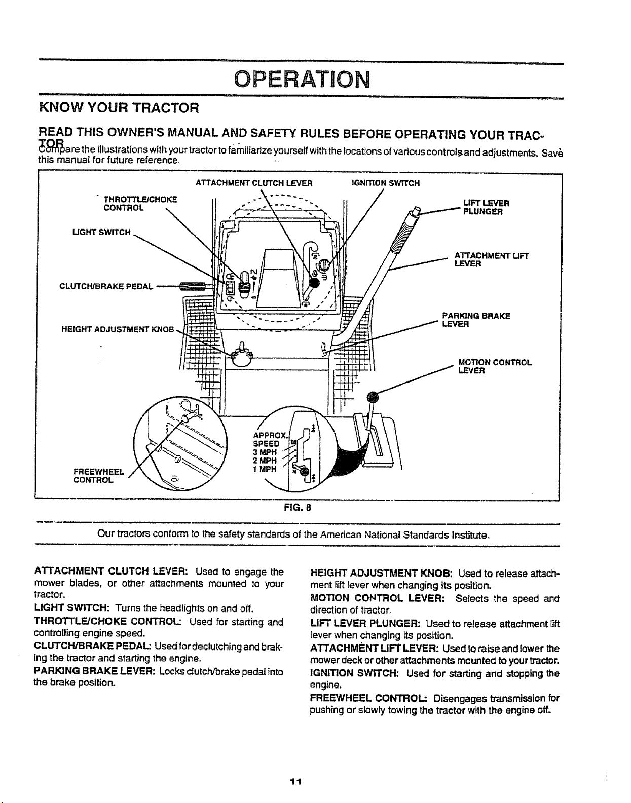
KNOW YOUR TRACTOR
READ THIS OWNER'S MANUAL AND SAFETY RULES BEFORE OPERATING YOUR TRAC-
_l:_a re the illustrations withyour tractortofamiliarize yourself withthe locationsof vadous control,_and adjustments. Sav_
this manual for future reference_ .....
THROTTLE/CHOKE
CONTROL
UGHT SWITCH
CLUTCH/BRAKE PEDAL
HEIGHT ADJUSTMENT
ATTACHMENT CLLrrCH LEVER IGNITION SWITCH
UFT LEVER
PLUNGER
ATTACHMENT UFT
LEVER
PARIQNG BRAKE
LEVER
MOTION CONTROL
LEVER
FREEWHEEL
CONTROL
APPROX.
SPEED
3 MPH
2 MPH
1 MPH
FIG. 8
Our tractors conform to the safety standards of the American National Standards Institute.
ATTACHMENT CLUTCH LEVER: Used to engage the
mower blades, or other attachments mounted to your
tractor°
LIGHT SWITCH: Turns the headlights on and off.
THROTTLE/CHOKE CONTROL: Used for starting and
controlling engine speed.
CLUTCH/BRAKE PEDAL: Used fordeclutching and brak-
ing the tractor and starting the engine.
PARKING BRAKE LEVER: Locksclutch/brake pedal into
the brake position.
HEIGHT ADJUSTMENT KNOB: Used to release attach-
ment lift lever when changing its position.
MOTION CONTROL LEVER: Selects the speed and
direction of tractor,
LIFT LEVER PLUNGER: Used to release attachment lift
lever when changing its position.
ATTACHMENT UFT LEVER: Used to raise and lower the
mowerdeck or other attachments mounted to your tractor,
IGNITION SWITCH: Used for starting and stopping the
engine.
FREEWHEEL CONTROL: Disengages transmissionfor
pushing or slowly towing the tractor with the engine off.
11
OPERATION
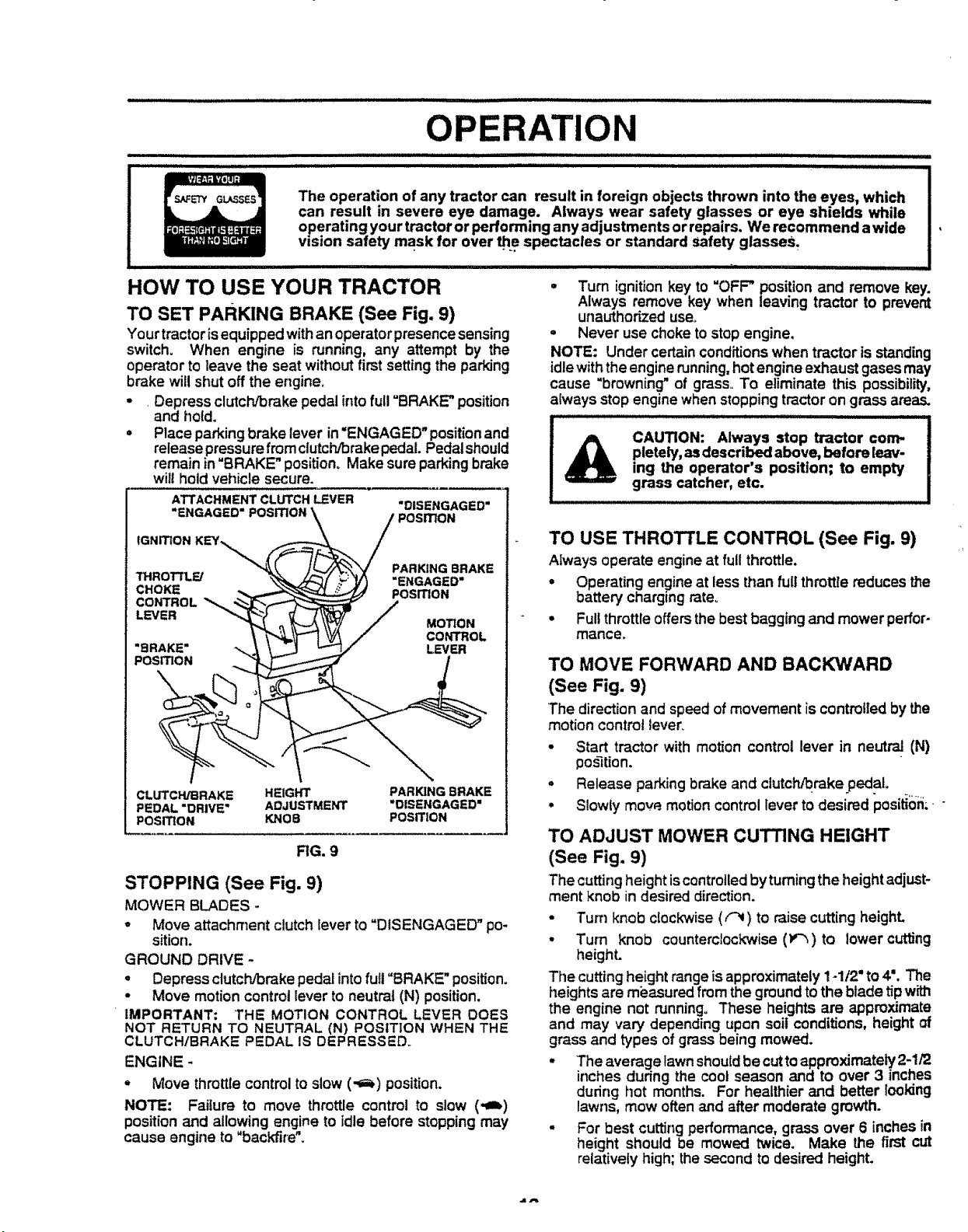
The operation of any tractor can result in foreign objects thrown into the eyes, which
can result in severe eye damage. Always wear safety glasses or eye shields while
operating your tractor or performing any adjustments or repairs. We recommend a wide
vision safety mask for over _e spectacles or standard safety glasses.
ATTACHMENTCLUTCH_VER
"ENGAGED"
"DISENGAGED =
POSITION
IGNITION KEY%,,_
PARKING BRAKE
THROT3"LFJ "ENGAGED"
CHOKE POSITION
CONTROL "_,
LEVER MOTION
CONTROL
"BRAKE" LEVER
POSITION
CLUTCH/BRAKE HEIGHT PARKING BRAKE
PEDAL "DRIVE" ADJUSTMENT "DISENGAGED"
POSITION KNOB POSITION
RG. 9
STOPPING (See Fig. 9)
MOWER BLADES -
• Move attachment clutch lever to "DISENGAGED" po-
sition.
GROUND DRIVE -
• Depress clutch/brake pedal into full "BRAKE" position.
• Move motion control lever to neutral (N) position.
IMPORTANT: 'THE MOTION CONTROL LEVER DOES
NOT RETURN TO NEUTRAL (N) POStTION WHEN THE
CLUTCH/BRAKE PEDAL IS DEPRESSED.
ENGINE -
- Move throttle control to slow (-1_) position.
NOTE: Failure to move throttle control to slow (-=i)
position and allowing engine to idle before stopping may
cause engine to "backfire".
• Turn ignition key to "OFF" position and remove key.
Always remove key when leaving tractor to prevent
unauthorized use.
• Never use choke to stop engine,
NOTE: Under certain conditions when tractor is standing
idle with the engine running, hot engine exhaust gases may
cause "browning" of grass° To eliminate this possibility,
always stop engine when stopping tractor on grass areas.
CAUTION: Always stop tractor com-
pletely, asdescribed above, before leav-
ing the operator's position; to empty
grass catcher, etc.
TO USE THROTTLE CONTROL (See Fig. 9)
Always operate engine at full throttle.
• Operating engine at less than full throttle reduces the
battery charging rate_
• Full throttle offers the best bagging and mower perfor-
mance,
TO MOVE FORWARD AND BACKWARD
(See Fig. 9)
The direction and speed of movement is controlled by the
motion control lever_
• Start tractor with motion control lever in neutral (N)
pos3tion.
• Release parking brake and clutch/brake pedal.
• Slowly mow motion control lever to desired position;"
TO ADJUST MOWER CUTTING HEIGHT
(See Fig. 9)
The cuttingheight iscontrolledby turning the heightadjust-
ment knob in desired direction.
• Turn knob clockwise ((-_) to raise cutting heighL
• Turn knob counterclockwise (_) to lower cutting
height.
The cutting height range is approximately 1-1/2 ° to 4 °. The
heights are mi_asured from the ground to the blade tipw_
the engine not running. These heights are approximate
and may vary depending upon soil conditions, height of
grass and types of grass being mowed.
• The average lawn should be cutto approximately 2-1/2
inches during the cool season and to over 3 inches
dudng hot months. For healthier and better looking
lawns, mow often and after moderate growth.
- For best cutting performance, grass over 6 inches in
height should be mowed twice. Make the first cut
relatively high; the second to desired height.
HOW TO USE YOUR TRACTOR
TO SET PARKING BRAKE (See Fig. 9)
Your tractor is equipped with an operator presence sensing
switch. When engine is running, any attempt by the
operator to leave the seat without first setting the parking
brake witl shut off the engine.
• Depress clutch/brake pedal into full "BRAKE" position
and hold.
• Place parking brake lever in "ENGAGED" positionand
release pressurefrom clutch!brakepedal. Pedalshould
remain in"BRAKE" position° Make sure parking brake
will hold vehicle secure.
OPERATION
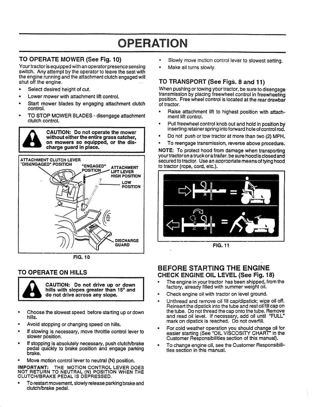
TO OPERATE MOWER (See Fig. 10)
Your tractor is equipped with an operator presence sensing
switch. Any attempt by the operator to leave the seat with
the engine running and the attachment cMch engaged will
shut off the engine.
- Select desired height of cut.
° Lower mower with attachment liftcontrol.
o Start mower blades by engaging attachment clutch
control.
° TO STOP MOWER BLADES - disengage attachment
clutch control.
CAUTION: Do not operate the mower
without either the entire grass catcher,
on mowers so equipped, or the dis-
charge guard in place.
ATTACHMENT CLUTCH LEVER
"DISENGAGED = POSITION
"ENGAGED"
ATTACHMENT
LEVER
HIGH POSiTiON
}' LOW
,_: " POSITION
J;
5"
__, DISCHARGE
GUARD
. Slowly move motion control lever to slowest setting.
o Make all turns slowly
TO TRANSPORT (See Figs. 8 and 11)
When pushing or towing y_ur tractor,be sure to disengage
transmission by placing freewheel control in freewheeling
position. Free wheet control is located at the rear drawbar
of tractor,
• Raise attachment lift to highest position with attach-
ment lift control.
• Pull freewheel control knob out and hold in positionby
inserting retainer spring into forward hole of control rod.
• Do not push or tow tractor at more than two (2) MPH.
• To reengage transmission, reverse above procedure.
NOTE: To protect hood from damage when transporting
your tractor on a truckor a trailer_ be sure hood is closed and
secured totractor° Use an appropriate means of tying hood,
to tractor (rope, cord, etc.).
FIG. 11
FIG. 10
TO OPERATE ON HILLS
CAUTION: Do not drive up or down
hills with slopes greater than 15° and
do not drive across any slope.
- Choose the slowest speed before starting up or down
hills.
° Avoid stopping or changing speed on hills.
° If slowing is necessary, move throttle control lever to
slower position.
= If stopping is absolutely necessary, push cMch/brake
pedal quickly to brake position and engage parking
brake.
- Move motion control lever to neutral (N) position.
IMPORTANT: THE MOTION CONTROL LEVER DOES
NOT RETURN TO NEUTRAL (N) POSITION WHEN THE
CLUTCHIBRAKE PEDAL IS DEPRESSED.
. To restartmovement, slowly release parkingbrake and
clutch/brake pedal,
BEFORE STARTING THE ENGINE
CHECK ENGINE OIL LEVEL (See Fig, 18)
- The engine in your tractor has been shipped, from the
factory, already filled with summer weight oil.
- Check engine oil with tractor on level ground.
• Unthread and remove oil fill cap/dipstick; wipe oil off.
Reinsert the dipstick into the tube and rest oil fill cap on
the tube. Do not thread the cap onto the tube. Remove
and read oil level, if necessary, add oil until "FULL"
mark on dipstick is reached_ Do not overfill.
° For cold weathei" operation you should change oil for
easier starting (See "OIL VISCOSITY CHART" in the
Customer Responsibilities section of this manual).
= To change engine oil, see the Customer Responsibili-
ties section in this manual.
................................ i i iii illii __
OPERATION
ADD GASOLINE
• Fill fuel tank. Use fresh, clean, regular unleaded
gasoline. (Use of leaded gasolinewilt increase carbon
and lead oxide deposits and reduce valve life). "
IMPORTANT: WHEN OPERATING IN TEMPERATURES'
BELOW 32°F(0"C), USE FRESH, CLEAN WINTER GRADE
GASOLINE TO HELP INSURE GOOD COLD WEATHER
STARTING.
WARNING: Experience indicates that alcohol blended
fuels (called gasohol or using ethanol or methanol) can
attract moisture whichleads toseparation and formation of
acids during storage. Acidic gas can damage the fuel
system of an engine while in storage. To avoid engine
problems, the fuel system should be emptied before stor-
age of 30 days or longer. Drain the gas tank, start the
engine and let it run until the fuel lines and carburetor are
empty. Use fresh fuel next season. See Storage Instruc-
tions for additional information° Never use engine or
carburetor cleaner products in the fue! tank or permanent
damage may occur°
usespilledfiUerneck.CAUTION:.............................................................................gasolineoil orDo not overfill.Fillfuel.nearto Doanbottomnotopenstore,Wipeofflame,gasspilloffanytankor !
iHll ill ,,,,,,,,,,,,,,,,,, , .......
TO START ENGINE (See Fig. 9)
When starting engine for the first time or if engine has run
out of fuel, it will take extra cranking time to move fuel from
the tank to the engine.
• Depress clutch!brake pedal and set parking brake.
• Place motion control lever in neutral (N) position.
° Move attachment clutch to "DISENGAGED" position.
° Move throttle control lever to choke (N) position for
cold engine start. Forwarm engine start,move throttle
control to fast (,_) position.
• insert key intoignitionand turnkey clockwiseto"START"
position and release key as soon as engine starts. Do
not run starter continuously for more than fifteen
seconds per minute. If engine does not start after
several attempts, move throttle control to fast (,_)
position, wait a few minutes and try again.
• When engine starts, slowlymove throttle control lever
to desired running speed.
- Allow engine to warm up for a few minutes before
engaging drive or attachments.
NOTE: If at a high altitude (above 3000 feet) or in cold
temperatu.res (below 32°F), the carburetor fuel mixture
may need to be adjusted for best engine performance. See
"TO ADJUST CARBURETOR" in the Service and Adjust-
ments section of this manual.
PURGE TRANSMISSION
........... |llllll i lu JiuiH i
CAUTION: Never engage or disengage
freewheel lever while the engine is run-
ning.
To ensure proper operation and performance, itis recom-
mended that the transmission be purged before operating
tractor for the first time° This procedure will remove any
trapped air insidethe transmission which may have devel-
oped during shippingof your tractor.
IMPORTANT: SHOULDYOUR TRANSMISSION REQUIRE
REMOVAL FOR SERVICE OR REPLACEMENT, IT
SHOULD BE PURGED AFTER REINSTALLATION
BEFORE OPERATING THE TRACTOR°
° Place tractorsafely onlevel surface with engineoff and
parking brake set.
" Disengage transmi_ion by placing freewheel control
in freewheeling po.=ition(See "TO TRANSPORT" in
this section of manual).
° Sittingin the tractorseat, startengine. Afterthe engine
isrunning, move throttlecontrolto slow (,qI_) position.
With motion controllever inneutral (N) position,slowly
disengage clutch/brake pedal.
° Move motion control lever to full forward positionand
hold for five (5) seconds. Move lever to full reverse
position and hold for five (5) seconds. Repeat this
procedure three (3) times.
NOTE: During this procedure therewill be no movement of
drive wheels. The airis being removed from hydraulicdrive
system.
° Move motion controlleverto neutral (N) position. Shut-
off engine and set parking brake.
• Engage transmissionby placing freewheel control in
drivingposition (See "TO TRANSPORT" in thissection
of manual).
• Sittingin the tractor seat, startenoine. Afterthe engine
is running, move throttle controi'to half (112) speed.
With motion controllever in neutral (N) position,slowly
disengage clutch/brake pedal
= Slowly move motion control lever forward, after the
tractor moves approximatelyfive (5) feet, slowlymove
motion control lever to reverse position. After the
tractor moves approximately five (5) feet return the
motion controllever to the neutral (N) position. Repeat
this procedure with the motion control lever three (3)
times.
• Your tractor is now purged and now ready for normal
operation.
MOWING TIPS
• Tire chains cannot be used when the mower housing
is attached to tractor.
o Mower should be properly leveled for best mowjn_
perforrnance_ See"TO LEVEL MOWER HOUSING in
the Service and Adjustments section of this manual.
o The left hand side of mower should be used for trim-
ming.
° Drive so that clippings are discharged onto the area
that has been cut. Have the cut area to the right of the
machine. This will result ina more even distribution of
clippings and more uniform cutting°
° When mowing large areas, start by turning to the right
so that clippings will discharge away from shn_bs,
fences, driveways, etc, After one or two rounds, mow
in the opposite direction making left hand turns until
finished (See Fig. 12 ).
° if gra_ is extremely tat!, it should be mowed twice to
reduce load and possible fire hazard from dried clip-
pings. Make first cut relatively high; the second to the
desired height.
= Do not mow grass when it is wet. Wet grass will plug
mower and leave undesirable clumps. Allow grass to
dry before mowing.
° Always operate engine at full throttle when mowing to
assure better mowing performance and proper dis-
charge of material. Regulate ground speed by select-
ing a low enough gear to give the mower cutting
performance as well as the quality of cut desired.
o When operating attachments, select a ground speed
that will suit the terrain and give best performance of
the attachment being used.
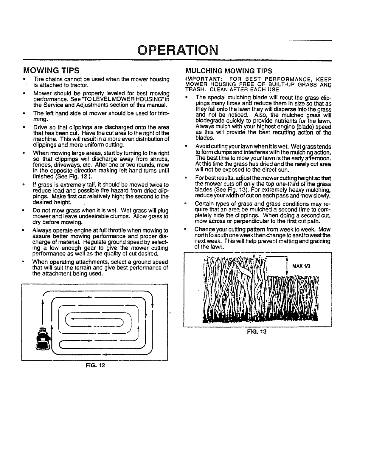
MULCHING MOWING TIPS
IMPORTANT: FOR BEST PERFORMANCE, KEEP
MOWER HOUSING FREE OF BUILT-UP GRASS AND
TRASH., CLEAN AFTER EACH LJSEo
° The special mulching blade will recut the grass clip-
pings many times and reduce them in size so that as
they fall onto the lawn they will disperse intothe grass
nd not be noticed. Also, the mulched grass will
iodegrade quickly to provide nutrients for the lawn.
Always mulch with your highest engine (blade) speed
as this will provide the best recutting action of the
blades.
° Avoid cuttingyour lawn when it is wet. Wet grass tends
to form ctumpsand interferes withthe mulchingaction.
The best timeto mow your lawn is the early afternoon.
At thistime the grass has dried and the newly cut area
will not be exposed to the direct sun.
° Forbest results, adjustthe mowercuttingheight sothat
the..mower cuts.Qffonly the top one=third of the grass
blades (See F=g.13). For _xtremely heav'_ mulching,
reduce yourwidth of cut on each pass and mow slowly.
° Certain types of grass and grass conditions may re-
quire that an area be mulched a second time to com-
pletely hide the clippings. When doing a second cut,
mow across or perpendicular to the first cut path.
° Change your cuttingpattern from week to week. Mow
north to south one week then change to east to west the
next week. This will help prevent matting and graining
of the lawn.
MAX I/3
FIG. 13
FIG, 12
i,, ,ill,i llll ...........................
,ll i,i
CUSTOMER RESPONSIBILITIES
/ ,,ill ii i '"' ' ..................................... iiiiiiill illllll illll i
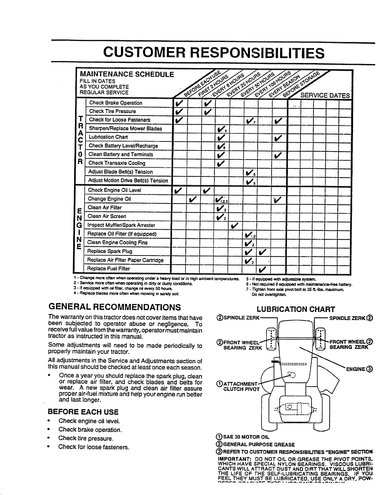
MAINTENANCE
FILL IN DATES
AS YOU COMPLETE
REGULAR SERVICE
IIIIIIIII I1'1 I
Check Brake Operation
,,,,,,,,, ,, ,, ,,,,
Check Tire Pressure
Check for Loose Fasteners
R Sharpen/Replace Mower Blades
! Lubricationchart
T Check Batten/Level/Recharge ....... I/_ .....
0 Clean Battery and Terminals
R CheckTtansaxieCooling If
AdjustBlade Belt(s) Tension
AdjustMotionDrive Belt(s)Tension
Check EngineOil Level ......... I,/ b/
Change Engine Oil If 1_,_3
E Clean AirR!ter ............... 1/2
N c_eanAir_oen............ - ...........i. _ _V'2
G i LnspectMuffler/SparkArrestet......... tf ..................
I Replace Oil Filler(If equipped) t_L2
Clean EngineCoolingFins li/z
Replace Spark Plug .... tk/
Replace Air Filler PaperCartridge i,/2
Replace Fuel Filter
1 - Ch=u-,gemona olton _n of>e_Cr_gunder a P,eaW load o_ in high ambient tampem_Jna_,
2 * SeP..icomorn often when of_t_g in _rty cA"_._/con_t_._
3 - tf e_Jip_oedwire oil furor,€_,_u,,geoil eve_ 50 houPJ.
4 - Reglaca bla_o,g_ often when mowir,_ in_ soil,.
i/ v'
v' ...............' :v', ......v' ....................
v' i/
v'
; " : : .........r _.. • :
W_s
i.....
-v'
v'
v'
i , 7 :
8 - Notmquved_ equ_ _ main_ b=t_rf.
7 oT_g_tanfrom _de pivotbo_tto 35 ft.*g0s,maximum.
Dorot ove_gnm_r'_.
GENERAL RECOMMENDATIONS
The warranty on thistractordoes not cover items that have
0een subjected to operator abuse or negligence. To
receive full value from the warranty,operator must maintain
tractor as instructed in thismanu_
Some adjustments will need to be made periodically to
properly maintain your tr_ctoro
All adjustments in the Service and Adjustments section of
this manual should be checked at least once each season.
o Once a year you should replace the spark plug, clean
or replace air fitter, and check btades and belts for
Wear. A new spark ptug and clean air filter assure
proper air-fuel mixture and heip your engine run better
and last Ionger.
BEFORE EACH USE
o Check engine oit level.
• Check brake operation.
° Check tire pressure,
o Check for loose fasteners.
LUBRICATION CHART
(_SPINDLE _)
(_FRONT WH
BEARING ZERK
C
CLUTCH PIVOT
®
(_SAE 30 MOTOR OIL
® GENERAL PURPOSE GREASE
® REFER TO CUSTOMER RESPONSlBiUTIES "ENGINE" SECTION
IMPORTANT: 00 NOT OIL OR GREASE THE PIVOT POINTS,
WHICH HAVE SPECIAL NYLON BEARtNGS_. VISCOUS LUBRI-
CANTS WILL ATTRACT OUST AND OtRT THAT WILL SHORTEN
THE LIFE OF THE SELF-LUBRICATING BEARINGS. IF YOU
FEEL THEY MUST BE LUBRICATED. USE ONLY A ORY, POW _
CUSTOMER P SIBILITI
TRACTOR
Always observe safety ruleswhen performing any mainte-
nance.
BRAKE OPERATION
If tractor requires more than six (6) feet stopping distance
at high speed_in highest gear, then brake must be.adjusted.
(See "TO ADJUST BRAKE" in the Service and Adjust-
ments section of this manual).
TIRES
• Maintain proper air pressure in all tires (See "PROD-
UCT SPECIFICATIONS" on page 3 of this manual).
= Keep tires free of gasoline, oil, or insect controlchemi-
cals which can harm rubber.
o Avoid stumps, stones, deep ruts, sharp objects and
other hazards that may cause tire damage.
BLADE CARE
For best results mower blades must be kept sharp_ Re-
place bent or damaged blades.
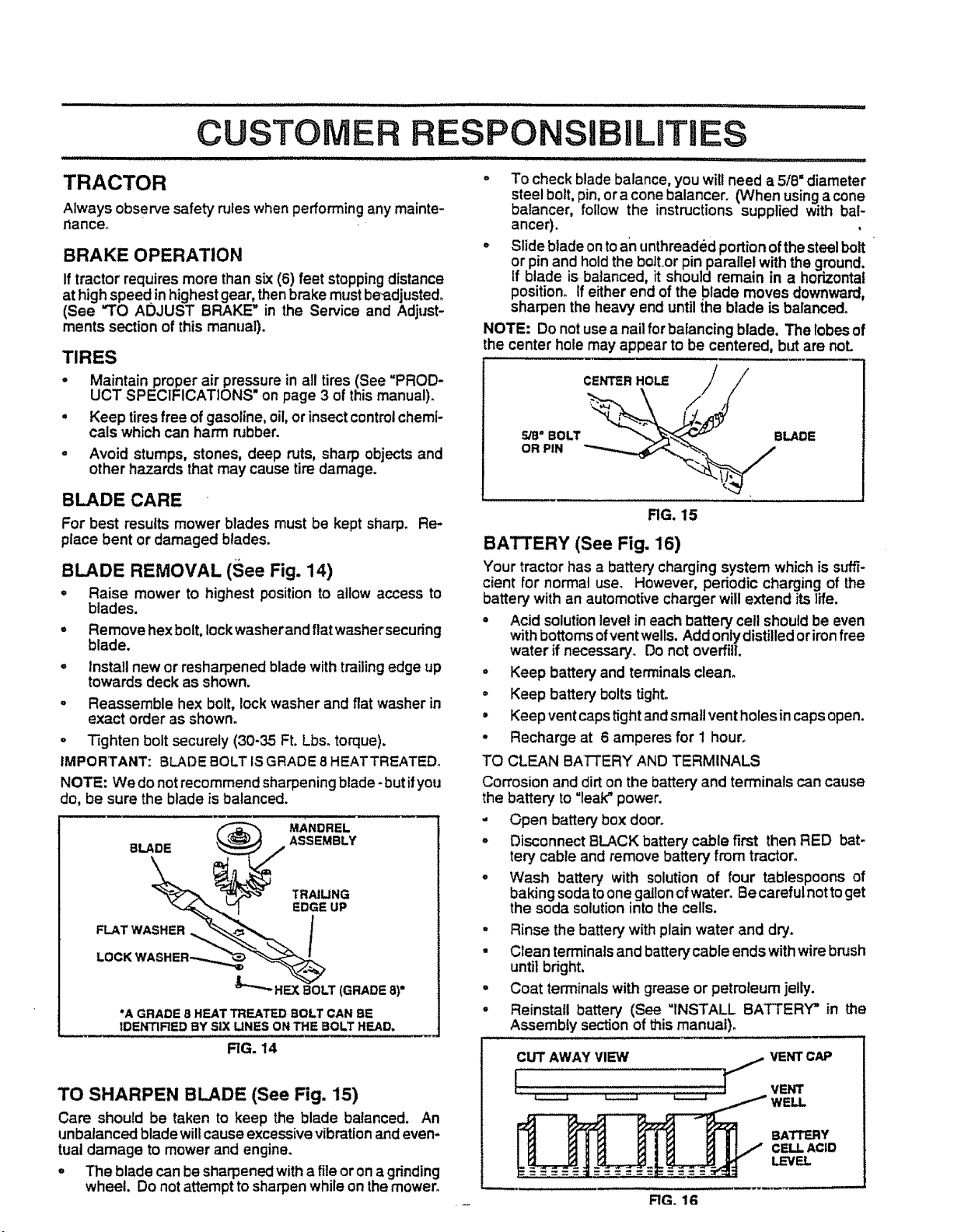
BLADE REMOVAL (See Fig. 14)
° Raise mower to highest position to allow access to
blades.
° Remove hex bolt, Iockwasherand ftat washersecuring
blade.
° install new or resharpened blade with trailing edge up
towards deck as shown.
o Reassemble hex bolt, lock washer and flat washer in
exact order as shown.
° Tighten bolt securely (30-35 Ft. Lbs. torque).
IMPORTANT: BLADE BOLT IS GRADE 8 HEATTREATED.
NOTE: We do not recommend sharpening blade- but ifyou
do, be sure the blade is balanced.
"A GRADE 8 HEAT TREATED BOLT CAN BE
IDENTIRED BY SiX LINES ON THE BOLT HEAD.
o To check blade balance, you wilt need a 5/8" diameter
steel bolt, pin, ora cone balancer. (When using acone
balancer, follow the instructions supplied with bal-
anger).
° Slide blade on toan unthreaded portionof the steel bolt
or pin and hold the boltor pin parallel with the ground.
If blade is balanced, it should remain in a horizontal
position. If either end of the blade moves downward,
sharpen the heavy end until {he blade is balanced.
NOTE: Do notuse a nail for balancing blade. The lobes of
the center hole may appear to be centered, but are noL
CENTER HOLE /
5/8" BOLT _BLADE
OR PIN
RG. 15
BATTERY (See Fig. 16)
Your tractor has a batterycharging system which is slfffi-
cient for normal use. However, periodic charging of the
battery with an automotive charger will extend its life.
° Acid solutionlevel in each battery cell should be even
with bottoms ofvent wells. Add onlydistilled oriron free
water if necessary° Do not overfill.
° Keep battery and terminals clean°
- Keep battery bolts tight.
= Keep vent caps tight and small vent holes in caps open.
° Recharge at 6 amperes for 1 hour.
TO CLEAN BATTERY AND TERMINALS
Corrosion and dirt on the battery and terminals can cause
the battery to "leak" power.
- Open battery box door.
° Disconnect BLACK battery cable first then RED bat-
tery cable and remove battery from tractor.
° Wash battery with solution of four tablespoons of
baking soda to one gallon ofwater. Be careful notto get
the soda solution into the cells.
° Rinse the battery with plain water and dry.
- Clean terminals and battery cable ends with wire brush
until bright.
• Coat terminals with grease or petroleum jelly.
• Reinstall battery (See "INSTALL BATTERY" in the
Assembly section of this manual).
RG. 14
TO SHARPEN BLADE (See Fig. 15)
Care should be taken to keep the blade balanced. An
unbalanced blade will cause excessive vibrationand even-
tual damage to mower and engine.
° The blade can be sharpened with a file oron a grinding
wheel. Do not attempt to sharpenwhile on the mower.
CUT AWAY VIEW VENTCAP
I S,o.,
_ _ WELL
BATTERY
CELL ACID
LEVEL
FIG. 1G
• i,iiiiilll i iiiiiii ii i iii lull _ _ I,,,1"11 _ IllU II ........................................
CUSTOMER RESPONSIBILITIES
............. • .................................. 111 11 , I IIIIII II I ...- II,lllUH II , II1,1,1,1 I
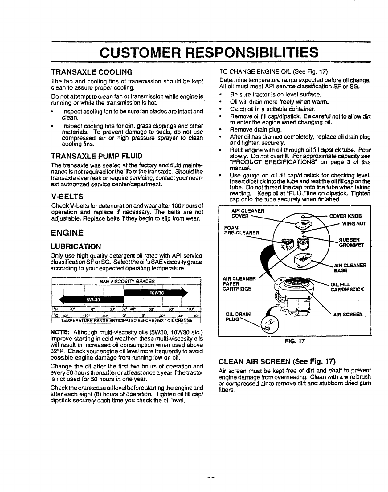
TRANSAXLE COOLING TO CHANGE ENGINE OIL (See Fig. 17)
The fan and cooling fins of transmission should be kept
clean to assure proper cooling,
Do not attempt to clean fan or transmission while engine is
running or while the transmission is hot.
° Inspect cooling fan to be sure fan blades are intact and
clean.
° Inspect cocklingfins for dirt, grass clippingsand other
materials. To prevent damage to seals, do not use
compressed air or high pressure sprayer to clean
cooling fins.
TRANSAXLE PUMP FLUID
The transaxle was sealed at the factory and fluid mainte-
nance is not required fort.he life ofthe transaxle. Should the
transaxle ever leak or require servicing, contactyour near-
est authorized service center/departmenL
V-BELTS
Check V--beltsfor deterioration andwear after 100 hours of
operation and replace if necessary. The belts are not
adjustable. Replace belts if they begin to slip from wear.
Determine temperature range expected before oil change.
All oil must meet API service classification SF or SG.
° Be sure tractor is on level surface.
• Oil will drain more freely when warm.
o Catch oil in a suitable _bhtainero
° Remove oil fill cap/dipstick, Re careful not to allow dirt
to enter the engine when changing oil.
° Remove drain plug.
° After oil has drained completely, replace oil drain plug
and tighten securely.
° Refill engine with oil through oil fill dipstick tube. Pour
slowly. Do not overfill. For approximate capacity see
"PROOUCT SPECIFICATIONS on page 3 of this
manual°
° Use gauge on oil fill capldipst_ckfor checking level.
insert dipstick into the tube and rest the oil fill cap onthe
tube. Do not thread the cap onto the tube when taking
reading. Keep oil at "FULL"line on dipsticK. Tighten
cap onto the tube securely when finished.
ENGINE
LUBRICATION
Only use high quality detergent oil rated with API service
classification SF or SGo Select the oil'sSAE viscosity grade
according to your expected operating temperature.
SAE VISCOSITY GRADES
°F -20" 0" 3_ 3,2" t0'* 8_ 80" 10_
°CC .30" .1_' .t0 • 0" t_ _ 30" 40"
TEM_-IRATLj'RE RANGE ANTICIPATED BI_FOFtI_ NEXT OIL CHANGE
NOTE: Although multi-viscosity oils (5W30, 10W30 etc.)
improve starting in cold weather, these multi-viscosity oils
will result in increased oil consumption when used above
32°F, Check your engine oil level more frequently to avoid
possible engine damage from running low on oil
Change the oil after the first two hours of operation and
every 50 hours thereafter or at least oncea year ifthe tractor
is not used for 50 hours in one year.
Checkthe crankcase oil level before starting the engineand
after each eight (8) hours of operation. Tighten oil fill cap/
dipstick securely each time you check the oil level.
AIR CLEANER
COVER
FOAM
PRE-CLEANER
COVER KNOB
WING NUT
RUBBER
CLEANER
BASE
NR CLEANER
PAPER _LL
CARTRIDGE CAP_IPS'RCK
OIL ORAIN AIR SCREEN _
FIG. 17
CLEAN AIR SCREEN (See Fig. 17)
Air screen must be kept free of dirt and chaff to prevent
engine damage from overheating. Clean with a wire brush
or compressed air to remove dirt and stubborn dried gum
fibers°
CUSTOMER RESPONSIBiLiTIES
AIR FILTER (See Fig. 17)
Your engine will not run properly using a dirty air fi_ter.
Clean the foam pro-cleaner after every 25 hours of opera-
tion or every season. Service paper cartridge every 100
hours of operation or ever,] season, whichever occurs fih3t.
Service air cleaner more often under dusty conditions.
• Remove knob and cover.
o Remove wing nut and air cleaner from base.
TO SERVICE PRE-CLEANER
= Slide foam pro-cleaner off cartridge.
° Wash it in liquid detergent and water.
o Squeeze it dry in a clean cloth.
, Saturate it in engine oil. Wrap it in clean, absorbent
cloth and squeeze to remove excess oil.
TO SERVICE CARTRIDGE
o Gently tap the flat side of the paper cartridge to dis-
lodge dirt. Do not wash the paper cartridge or use
pressurized air, as this will damage the cartridge.
Replace a dirty, bent, or damaged cartridge.
° Reinstall the pre-cleaner (cleaned and oiled) over the
paper cartridge.
= Reassemble air cleaner, wing nut, cover and tighten
knob securely.
CLEAN AIR INTAKE/COOLING AREAS
To insure proper cooling, make sure the grass screen,
coolingfins, and other extemal surfaces of the engine are
kept clean at all times.
Every 100 hours of operation (more often under extremely
dusty, dirty conditions), remove the blower housing and
other cooling shrouds. Clean the cooling fins and external
surfaces as necessary. Make sure the cooling shrouds are
reinstalled.
NOTE: Operating the engine with a blocked grass screen,
dirty or plugged cooling fins, B.nd/or cooling _hm_ds re-
moved will cause engine damage due to overheating.
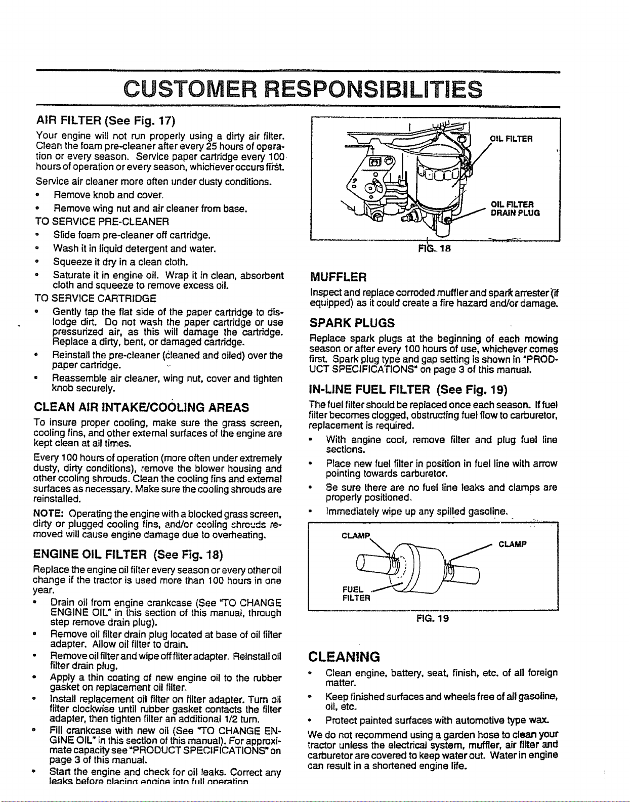
ENGINE OIL FILTER (See Fig. 18)
Replace the engine oil filter every' season or every other oit
change if the tractor is used more than 100 hours in one
year.
° Drain oil from engine crankcase (See "TO CHANGE
ENGINE OIL" in this section of this manual, through
step remove drain plug).
° Remove oil filter drain plug located at base of oil filter
adapter. Allow oil filter to drain.
= Remove oilfilter and wipe off filteradapter. Reinstalloil
filter drain plug.
o Apply a thin coating of new engine oil to the rubber
gasket on replacement oil filter.
o Install replacement oil filter on filter adapter. Turn oil
filter clockwise until rubber gasket contacts the filter
adapter, then tighten filter an additional 1/2 turn.
° Fill crankcase with new oil (See "TO CHANGE EN-
GINE OIL" in this section of this manual). For approxi-
mate capacity see =PRODUCT SPECIFICATIONS* on
page 3 of this manual.
= Start the engine and check for oil teaks. Correct any
leaks before mlnninn _.nnin_.intn fl_llnn_mtinn
OiL RLTER
OIL FILTER
DRAIN PLUG
Rials
MUFFLER
Inspect and replace corrodedmuffler and spark an'ester_if
equipped) as it could create a fire hazard and/or damage,
SPARK PLUGS
Replace spark plugs at the beginning of each mowing
season or after every 100 hours of use, whichever comes
first. Spark plug type and gap setting is shown in "PROD-
UCT SPECIFICATIONS" on page 3 of this manual.
IN-LINE FUEL FILTER (See Fig. 19)
The fuel filter shouldbe replaced once each season, if fuel
filter becomes clogged, obstn_ctingfuel flow to carburetor,
replacement is required.
° With engine coot, remove filter and plug fuel line
sections.
o
o
o
Place new fuel filter in position in fuel line with arrow
pointing towards carburetor.
Be sure there are no fuel line leaks and clamps are
ptopedy positioned.
Immediately wipe up any spil!ed gasoline.
i ....
CLAMP
FU_ CLAMP
FILTER
RG. 19
CLEANING
° Clean engine, battery, seat, finish, etc. of all foreign
matter.
- Keep finishedsurfaces and wheels free of all gasoline,
oil, etc.
° Protect painted surfaces with automotive type wax.
We do not recommend using a garden hose to clean your
tractor unless the electrical system, muffler, air filter and
carburetor are covered to keep water out. Water in engine
can result in a shortened engine life.
SERVICE AND ADJUSTMENTS
irlllll ill l
illlllllll ill i lll illlii u i iiiulll ii ,mlU illlll ii ill, ,.........
CAUTION: BEFORE PERFORMING ANY SERVICE OR ADJUSTMENTS:
Depress clutchJbrake pedal fully and set parking brake.
Place motion control lever rn neutral (N) position.
Ik"l lull ii
iiiiJl!
Place attachment clutch in "DISENGAGED" position.
Turn ignition key "OFF" and remove key.
• Make sure the blades and all moving parts have completely stopped.
° Disconnect spark plug wire from spark plug and place wire where it cannot come In contact with
plug.
................ ............... ............................ _[ IIII '11111' ,, i, I iii1,, ii, , ,
TRACTOR
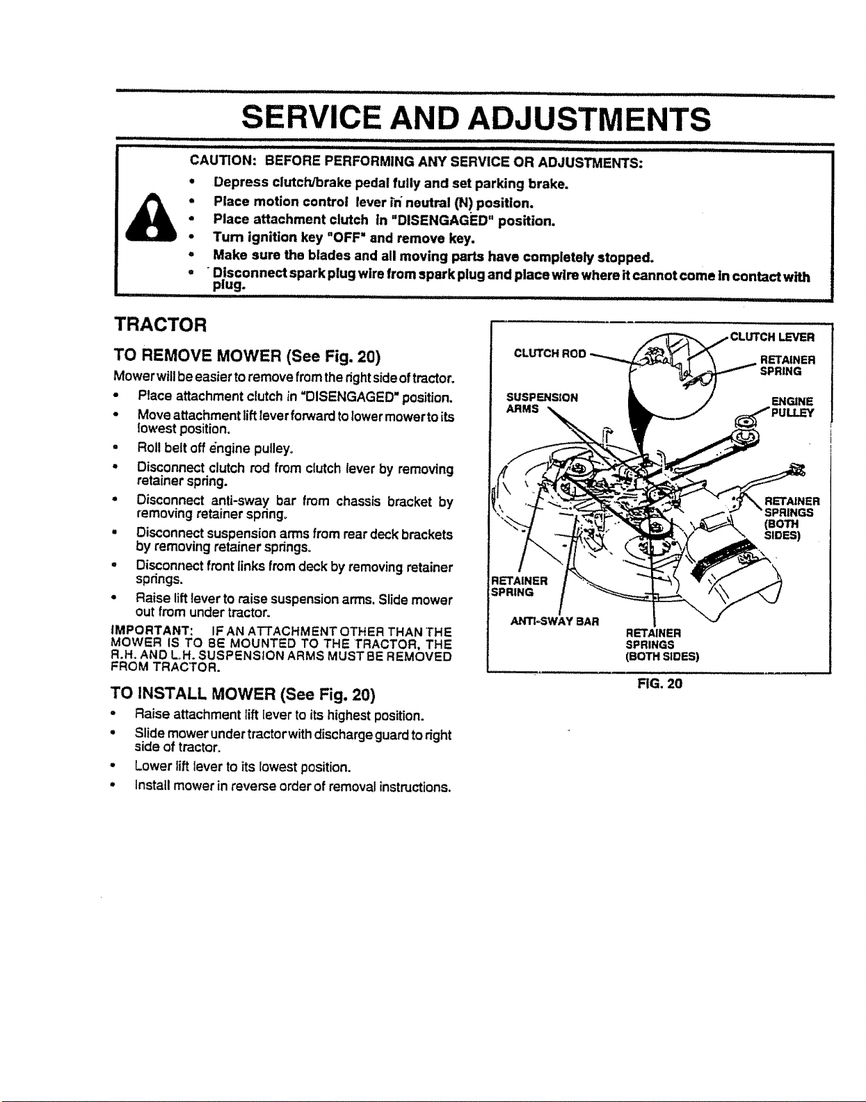
TO REMOVE MOWER (See Fig. 20)
Mower willbe easier to remove from the rightsideof tractor.
• Place attachment clutch in "DISENGAGED" position.
• Move attachment lift lever forwardto lower mower to its
lowest position.
, Roll belt off engine pulley°
• Disconnect clutch rod from clutch lever by removing
retainer spdng.
• Disconnect anti-sway bar from chassis bracket by
removing retainer spnngo
• Disconnect suspensionarms from rear deck brackets
by removing retainer springs.
, Disconnect front links from deck by removing retainer
springs.
• Raise lift lever to raise suspensionarms. Slide mower
out from under tractor.
IMPORTANT: IFAN ATTACHMENT OTHER THAN THE
MOWER IS TO 8E MOUNTED TO THE TRACTOR. THE
R.H. AND L.H. SUSPENSION ARMS MUST BE REMOVED
FROM TRACTOR.
TO INSTALL MOWER (See Fig. 20)
, Raise attachment lift lever to its highest position.
• Slide mower undertractorwith discharge guard to right
side of tractor.
• Lower liftlever to its lowest position.
• Installmower in reverse order of removal instructions.
CLUTCP
ARMS
RETAINER
SPRINGS
(BOTH SIDES)
RG. 20
i= UlU
LEVER
RETAINER
SPRING
ENGINE
RETAINER
(eoTH
SIDES)
,ll,llllll ,ll,l l, i ,
SERVICE AND ADJUSTMENTS
,i,,i iii,i Lr_ll
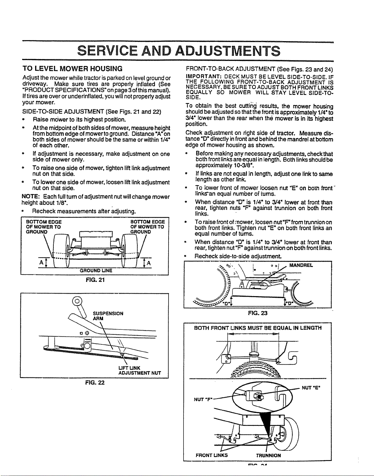
TO LEVEL MOWER HOUSING FRONT-TO-BACK ADJUSTMENT (See Figs. 23 and 24)
Adjust the mower while tractor is parked on level ground or
driveway. Make sure tires are properly !nllated (See
"PRODUCT SPECIFICATIONS" on page 3 of this manual).
tf tires are over or underinflated, you will not properly adjust
your mower°
SIDE-TO-SIDE ADJUSTMENT (See Figs. 21 and 22)
= Raise mower to its highest position.
° At the midpoint of both sidesof mower, measure height
from bottom edge of mower to ground. Distance "A" on
both sides of mower should be the same or within 1/4"
IMPORTANT: DECK MUST BE LEVEL SIDE-TO-SIDE. IF
THE FOLLOWING FRONT-TO-BACK ADJUSTMENT IS
NECESSARY, BE SURETO ADJUST BOTH FRONT LINKS
EQUALLY SO MOWER WILL STAY LEVEL SIDE-TO-
SIDE.
To obtain the best cutting results, the mower housing
should be adjusted so thatthe front isapproximately 1/4" to
3/4" lower than the rear when the mower is in its highest
position.
Check adjustment on right side of tractor. Measure dis-
tance "D" directly infront and behind the mandrel at bottom
of each other.
° If adjustment is necessary, make adjustment on one
side of mower only.
,, To raise one side of mower, tighten lift linkadjustment
nut on that side.
° To lower one side of mower, loosen liftlinkadjustment
nut on that side.
NOTE: Each full turn of adjustment nut willchange mower
height about 118".
o Recheck measurements after adjusting.
BOTTOM EDGE BOTTOM EDGE
OF MOWER TO OF MOWER TO
TV It....TT£
GROUND UNE
edge of mower housing as shown.
- Before makingany necessary adjustments, checkthat
both front links are equal inlength. Bothlinksshouldbe
approximately 10-3/8".
- If links are not equal in length, adjust one link to same
length as other link.
• To lower front of mower loosen nut =E" on born front
tinL_'an equal number of turns°
• When distance "D" is 1/4" to 3/4 ° lower at front than
rear, tighten nuts "F" against trunnion on both front
links.
• To raise frontofmower, loosen nut=F"from trunnion on
both front links. Tighten nut "E" on both front linksan
equal number of turns.
i When distance "D" is 1/4° to 3/4" lower at front than
rear, tightennut"F" against trunnion on both frontlinks.
• Recheck side-to-side adjustment.
RG. 21
SUSPENSION
ARM
\
LIFT LINK
ADJUSTMENT NUT
FIG. 22
FIG. 23
BOTH FRONT LINKS MUST BE EQUAL IN LENGTH
NUT "E"
FRONT LINKS
SERVICE AND ADJUSTMENTS
IlJJ Jl I IIIllll I IIIIIIII III L IIIII .......................
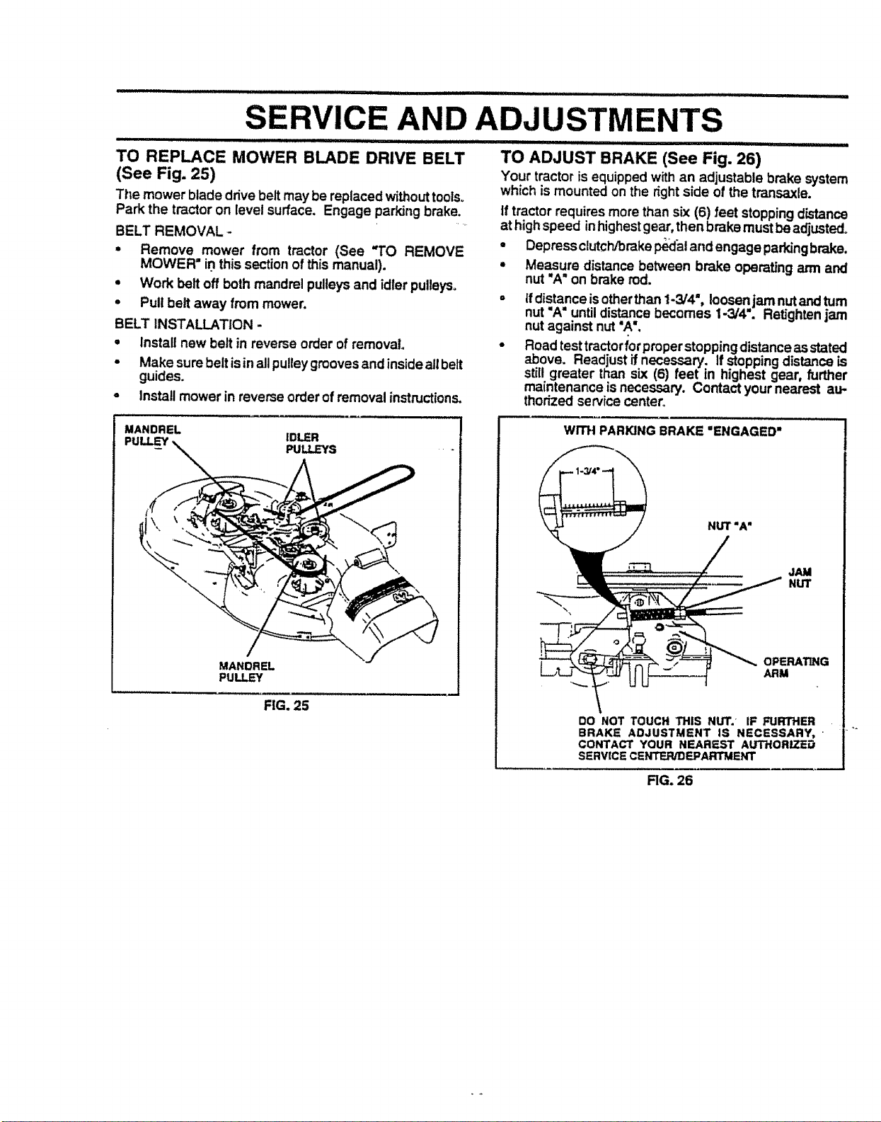
TO REPLACE MOWER BLADE DRIVE BELT
(See Fig. 25)
The mower blade drive belt may be replaced without tools_
Park the tractor on level surface, Engage parking brake.
BELT REMOVAL .*
• Remove mower from tractor (See "TO REMOVE
MOWER =in this section of this manual).
• Work belt off both mandrel pulleys and idler pulleys°
- Pull belt away from mower.
BELT INSTALLATION -
', Install new belt in reverse order of removal
, Make sure belt is inall pulleygrooves and inside all belt
guides.
• Install mower in reverse order of removal instructions.
TO ADJUST BRAKE (See Fig. 26)
Your tractor is equipped w_h an adjustable brake system
which is mounted on the _ght side of the transaxle.
tf tractor requires more than sLx(6) feet stopping distance
at high speed inhighestgear, then brake must be adjusted.
- Depressclutch_rake p_al and engage parkingbrake.
,, Measure distance between brake operating arm and
nut "A" on brake rod.
Ifdistance is otherthan 1-3/4", loosenjam nut andturn
nut "A" until distance becomes 1-3/4". RetJghtenjam
nut against nut "A'.
Road test tractoriorproperstoppingdistance as stated
above. Readjust if necessary. If stoppingdistance is
still greater than six (6) feet in highest gear, further
maintenance is necessary. Contact your nearest au-
thorized service center.
MANDREL
PULLEY IDLER
- PULLEYS
MANDREL
PULLEY
FIG. 25
WITH PARKING BRAKE "ENGAGED"
JAM
NUT
OPERATLNG
ARM
DO NOT TOUCH THIS NUT.' IF FURTHER
BRAKE ADJUSTMENT IS NECESSARY, • /
CONTACT YOUR NEAREST AUTHORIZ'iED
J
SERVICE CENTER/DEPARTMENT
RG. 26

TO REPLACE MOTION DRIVE BELT
(See Fig. 27)
Park the tractor on level surfacer Engage parking brake.
For assistance, there is a belt installation guide deca_ on
bottom side of left footrest.
• Remove mower (See "TO REMOVE MOWER" in this
section of this manual.)
. Remove upper belt keeper.
° Remove belt from stationary idler and clutching idler.
° Pull belt slack toward rear of tractor. Carefully remove
belt upwards from transmissioninput pulley and over
cooling fan blades.
- Pull belt toward front of tractor and remove downward
from around engine pulley°
• Install new belt by reversingabove procedure.
IMPORTANT: MAKE SURE UPPER BELT KEEPER 1S
POSITIONED PROPERLY BETWEEN LOCATOR TABS,
E.G,.E----._Ii
- IVI
INPUT PULLEY _,
I
,I LOCATOR
TABS
KEEPER
RG. 27
TO ADJUST MOTION CONTROL LEVER
(See Fig. 28)
The motioncontrollever has been preset at the factory and
adjustment should notbe neces.sary.
tf for any reason the motion control lever will not hold its
positionwhile at a selectedspeed, _tmay be adjustedatthe
fdction pack located on the right side of transmission.
= Park tractor on level surface. Stop tractor by turning
ignition key to "OFF" position, and engage parking
brake.
° Adjust motion control lever by tightening adjustment
lock,nut one half (1/2) turn.
NOTE: if for any mason the effort to move the motion
control lever becomes too excessive, reverse the above
adjustment procedureby loosening Iocknut 1/4 to 1,'2turn.
Road test tractor after adjustment and repeat procedure if
necessary.
i ,i ...........
ADJUSTMENT
LOCKNUT
FIG. 28
TRANSMISSION REMOVAL/REPLACEMENT
Should your transmission require removal for service or
replacement, it should be purged after reinstallation and
before operating the tractor. See "PURGE TRANSMIS-
SION" in Opgration section of this manual,
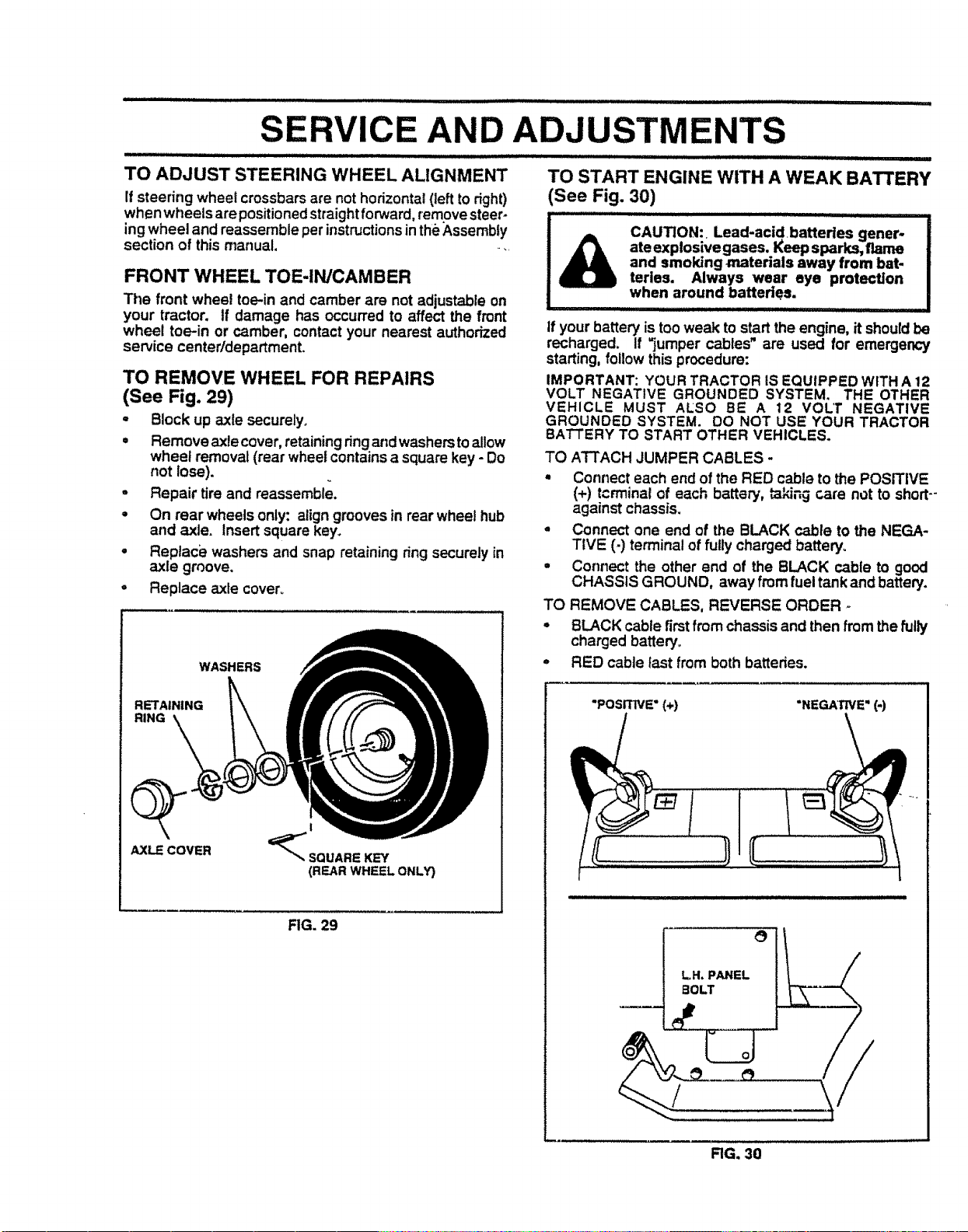
ill i i i,illll i IIIIIIH"' " ............... ''_'' ........................ '""_ _ I : IIlllll '1 ................
SERVICE AND ADJUSTMENTS
TO ADJUST STEERING WHEEL ALIGNMENT
If steering wheel crossbars are nothorizontal (left to right)
when wheels are positionedstraightforward, remove steer-
ing wheel and reassemble per instructionsinthe Assembly
section of this manual.....
FRONT WHEEL TOE-IN/CAMBER
The front wheel toe-in and camber are not adjustable on
your tractor. If damage has occurred to affect the front
wheel toe-in or camber, contact your nearest authorized
service center/department.
TO REMOVE WHEEL FOR REPAIRS
(See Fig. 29)
- Block up axle securely.
= Remove axle cover, retainingringandwashers to allow
wheel removal (rear wheel containsa square key - Do
not lose).
° Repair tire and reassemble.
° On rear wheels only: align grooves in rear wheel hub
and axle. Insert square key.
• Reptaci_ washers and snap retaining ring securely in
axle groove.
° Replace axle cover°
RETAINING
RING
AXLE COVER
i
_SQUARE KEY
(REAR WHEEL ONLY}
FIG. 29
WASHERS
TO START ENGINE WITH A WEAK BATTERY
(See Fig. 30)
..................................................... iUil,llll II I '
CAUTION: Lead-acid batteries gener-
ate explosive gases. Keep sparks, flame
and smoking m_terials away from bat-
teries. Always wear eye protection
when around batteries.
If your battery is too weak to start the engine, it should be
recharged. If "jumper cables" are used for emergency
starting, follow this procedure:
IMPORTANT: YOUR TRACTOR iS EQUIPPED WITH A 12
VOLT NEGATIVE GROUNDED SYSTEM. THE OTHER
VEHICLE MUST ALSO BE A 12 VOLT NEGATIVE
GROUNDED SYSTEM. DO NOT USE YOUR TRACTOR
BATTERY TO START OTHER VEHICLES.
TO ATTACH JUMPER CABLES -
- Connect each end of the RED cable to the POSITIVE
(+) terminal of each battery, taking cam not to short--
against chassis.
- Connect one end of the BLACK cable to the NEGA-
TIVE (-) terminal of fully charged battery.
• Connect the other end of the BLACK cable to good
CHASSIS GROUND, away from fuel tankand batten/.
TO REMOVE CABLES, REVERSE ORDER o
° BLACK cable firstfrom chassis and then fromthe fully
charged battery.
° RED cable fast from both batteries.
"POSITIVE" (+) "NEGAT'NE" (-)
LH. PANEL
BOLT
RGo 30
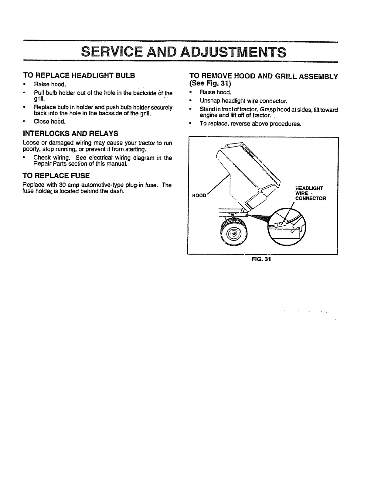
TO REPLACE HEADLIGHT BULB
=, Raise hood°
o Pull bulb holder out of the hole in the backside of the
grill. ....
° Replace bulb in holder and push bulb holder securely
back into the hole in the backside of the grill.
= Close ho_t.
INTERLOCKS AND RELAYS
Loose or damaged wiring may cause your tractor to run
poorly, stop running, or prevent it from starting°
° Check wiring. See electrical wiring diagram in the
Repair Parts section of this manual.
TO REPLACE FUSE
Replace with 30 amp automotive-type plug-in fuse. The
fuse holde[ is located behind the dash.
TO REMOVE HOOD AND GRILL ASSEMBLY
(See Fig. 31)
° Raise hood,
° Unsnap headlight wireconnector.
° Stand in front oftractor, Grasp hood at sides,tilttoward
engine and lift off of tractor.
° To replace, reverse above procedures.
HOOD
FIG. 31

SERVICE AND ADJUSTM
ENGINE
TO ADJUST THROTTLE CONTROL CABLE
(See Fig. 32) ....
The throttle control has been preset at the factory and
adjustment shouldnot be necessary. Check adjustmentas
described below before loosening cable. If adjustment is
necessary, proceed as follows:
o With engine not running, move throttle control lever
from slow (-_) to choke (hi) position. Slowly move
lever from choke (hi) to fast (,_) position.
• Check to see if hole in throttlelever and hole in speed
control bracket are aligned.
= If holes are not aligned, loosen cable clamp screw and
align the holes by inserting a pencil or a 1/4" drill bit
through both holes°
° Pul! throttle cable up to remove slack and tighten cable
clamp screw. Remove alignment pencil or ddtl bit.
TO ADJUST CARBURETOR (See Fig. 33)
The carburetor has been preset at the factory and adjust-
ment should not be necessary, However, minor adjust-
ment may be required to compensate fordifferencesin fuel,
temperature, altitude or load. tf the carburetor does need
adjustment, proceed as follows:
tn general, turning the adjusting needles in (clockwise)
decreases the supply of fuel to the engine giving a leaner
fuel/air mixture. Turningthe adjusting needles out (counter°
clockwise) increases the supplyof fuel to the engine giving
a richer fuel/air mixture.
IMPORTANT; DAMAGE TO THE NEEDLES AND THE
SEATS IN CARBURETOR MAY RESULT IF NEEDLE IS
TURNED IN TOO TIGHT_
PRELIMINARY SETTING -
• Be sure you have a clean air filter and the throttle
control cable is adjusted propedy (see above).
• With engine offturn idle fuel adjusting needle in (clock-
wise) closing it finger tight and then turn out (counter-
clockwise) 1 turn°
FINAL SETTING.
• Start engine and allow to warm for five minutes. Make
final adjustments with engine running and shift/motion
control lever in neutral (N) position.
° id!e soeed s_tting - With throttle control lever in stow
(-g_) position, engine should idle at 1750 RPM. If
engine idles too slow or fast, turn idle speed adjusting
screw in or out until correct idle is attained.
° !d!e fue! n_dle settinq - With throttle control lever in
slow (-,rob) position, turn idle fuel adjusting needle in
(clockwise) until engine beginsto die and then turn out
(counterclockwise) approximately 1/8 to 1/4 turn to
ontain t_estlow speed performance.
- Recheck idle speed. Readjust if necessary.
ACCELERATION TEST -
• Move throttle control lever from slow (,_b) to fast (,to)
position. If engine=hesitates ,or dies, turn idle fuel'
adjusting needle out (counterclockwise) 1/8 turn. Re-
peat test and continue to adjust, if necessary, until
engine accelerates smoothly.
High speed stop is factory adjusted. Do not adjust -
damage may result.
IMPORTANT; NEVER TAMPER WITH THE ENGINE
GOVERNOR, WHICH IS FACTORY SET FOR PROPER
ENGINE SPEED. OVERSPEEDJNG THE ENGINE ABOVE
THE FACTORY HIGH SPEED SETTING CAN BE
DANGEROUS. IF YOU THINK THE ENGINE-GOVERNED
HIGH SPEED NEEDS ADJUSTING, CONTACT YOUR
NEAREST AUTHORIZED SERVICE CENTER/
DEPARTMENT, WHICH HAS PROPER EQUIPMENT AND
EXPERIENCE TO MAKE ANY NECESSARY
ADJUSTMENTS,
CAB_
CLAMP
SCREW,
LEVER
FIG. 32
tDE .SPEED
ADJUS13NG
ADJUSTING
NEEDLE
RG. 33
STORAGE
Immediately prepare your tractor for storage at the end of
the season or if the tractor will not be used for 30 days or
more°
iiiii,Uil,lllll i i
CAUTION: Never store the tractor with
gasoline in the tank inside a building
where fumes may reach an open flame
or spark. Allow the engine to cool
before storing in any enclosure.
II III II II
TRACTOR
o
o
Remove mower from tractor for winter storage. When
mower is to be stored for a penod of time, clean it thor-
oughly, remove all dirt, grease, leaves, etc. Store in a
clean, dry area°
. Clean entire tractor (See =CLEANING" inthe Customer
Responsibilitiessection of this manual).
o _nspect and replace belts, if necessary (See belt re-
placement instructionsinthe Service and Adjustments
section of this manual).
Lubricate as shown in the Customer Responsibilities
section of this manual.
Be sure that all nuts, bolts and screws are securely
fastened. Inspect moving parts fordamage, breakage
and wear. Replace if necessary.
Touch up all rusted or chipped paint surfaces; sand
lightly before painting.
BATTERY
- Fully charge the battery for storage.
° After a period of time in storage, battery may require
recharging.
° To help prevent corrosion and power leakage during
long periods of storage, battery cables should be
disconnected and battery cleaned thoroughly (see "TO
CLEAN BATTERY AND TERMINALS" in the Cus-
tomer Responsibilities section of this manual).
° After cleaning, leave cables disconnected and place
cables where they cannot come in contact with battery
terminals.
• Be sure battery drain tube is securely attached.
° If battery' is removed from tractor for storage, do not
store battery directly on concrete or damp surfaces.
ENGINE
FUEL SYSTEM
IMPORTANT: IT IS IMPORTANT TO PREVENT GUM
DEPOSITS FROM FORMING IN ESSENTIAL FUEL
SYSTEM PARTS SUCH A_ CARBURETOR, FUEL FILTER,
FUEL HOSE, OR TANK DURING STORAGE. ALSO,
EXPERIENCE INDICATES THAT ALCOHOL BLENDED
FUELS (CALLED GASOHOL OR USING ETHANOL OR
METHANOL) CAN ATTRACT MOISTURE WHICH LEADS
TO SEPARATION AND FORMATION OF ACIDS DURING
STORAGE. ACIDIC GAS CAN DAMAGE THE FUEL
SYSTEM OF AN ENGINE WHILE IN STORAGE°
- Drain the fuel tank.
. Start the engine and let it run until the fuel lines and
carburetor are empty.
- Neveruse engine or carburetorcleaner productsin the
fuel tank or permanent damage may occur.
• Use fresh fuel next season.
NOTE: Fuel stabilizer is an acceptable alternative in
minimizing the formation of fuel gum deposits duringstor-
age, Add stabilizer to gasoline in fuel tank or storage
container, Always follow t.hemix ratio found on stabilizer
container, Run engine at least 10 minutes after adding
stabilizer to allowthe stabilizerto reach the carburetor. Do
not drain the gas tank and carburetorif using fuel stabilizer,
ENGINE OIL
Drain oil (with engine warm) and replace with clean engine
oil, (See =ENGINE" in the Customer Responsibilities
section of this manual),
CYLINDERS
° Remove spark plug(s),
• Pbur one ounce of oil through spark plug hole(S) into
cylinder(s)o
• Turn _,.3nitionkey to "START" position foca few seconds.
to distributeoil. -
= Replace with new spark ptug(s).
OTHER
= Do not store gasoline from one season to another.
° Replace your gasoline can if your can starts to rust.
Rust and/or dirt in your gasoline will cause problems.
° If possible, store your tractor indoors and cover it to
give protection from dust and dirt.
= CoveryOur tractor with a suitable protective cover that
does not retain moisture. Do not use plastic. Plastic
cannot breathe which allows condensation to form and
will cause your tractor to rust.
IMPORTANT: NEVER COVER TRACTOR WHILE ENGINE
AND EXHAUST AREAS ARE STILL WARM.

ii i/,,, ,, ,,, ..........................
i i i iiiiii iii ii iiiiii [ iiiUl ....... i[,1!1..
TROUB
PROBLEM
Wtll not start
: iiiiiiiiiii i iiiiii ii i iii
Hard to start
Engine will not turn over
Engine ct|cka but will not
start
Lmss of power
Exca_ive vibration
CAUSE
I. Out of fuel
2. Engine not'CHOKED" properly,
3. Engine flooded.
4. Bad spark plugo
5. Dirty air fitter.
6, Dirty fuel filter.
7. Water in fuel,
8. Loose or damaged widng,
9. Carburetor out of adjustmanL
10, Engine valves out of edJuslmanL
1o Dirtyairfilter,,
2. Badsparkplug,
3, Weak or dead battery_
4o Dirty,fuel filter..
5_ Stale or dirtyfuel.
6 LOO_eor damagedwff,ng.
7 Carburetoroutof adJus_nent,
8. Enginevalvesoutof adjustment,
1_ Clutctv'breke pedal not depressed.
2. Attachment cfutctt is engaged.
3, Weak or dead battery.
4, Blown fuse,
5, Corroded battery terminaL_
B, Loose or damaged widng.
7, Faulty ignition switch.
8. Faulty solenoid or starter°
9. Faulty operator presenoa switc.h(es).
1. Weak or dead battery.
2, Corroded battery terminals.
3o Loose or damaged widng.
4. Faulty solenoid or starter.
1o Cuing too much gross/too fast.
2. Thro_e in "CHOKE" position.
3, Build-up of grass, leaves and trash under mower.
4, Dirt/airfi_r,
5. Low oil tevelJdirtyoil,
6. Faulty spark plug,
7, Dirtyfuel filter,
8,, Stale or dirty fuel.
9, Water infuel.
10. Spank plug wire loose.
11o Ditty engine air screeru'flneo
12, Oirtyldogged muffler_
13. Loose or damaged widng_
14. Carburetor out of adjustment.
15. Engine valves out of ed|ustment.
iiii Iltt i ......................
1, Worn, bent or loose blade.
2. Bent blade mandrel,,
3. Loose/damaged part(s),
DOTING POINTS
CORRECTION
1. Fill fuel
2_ See "TO START ENGINE" tn Operation section.
3, Walt several minutes before attempting to start,
4. Replace spark plug.
5, Clean/replace air fi_ter_
6. Replace fuel fitter.
7. DreJn fuel tank and carburetor, refill tank with fresh
gasoline and replace fuel filter,
8. Check all wiring.
9, Contact an auff_dzed service center/depaztmenL
10, Contact an autt',odzed service centedde_nt.
2`
3.
4,
Io
2`
3.
4.
5,
6.
7.
8.
9,
10,.
11.
12.
13,
14.
15,
1,.
2"
3.
I_ Clean/replace air rifler,.
2. Replace spark plug,
3. Recharge or replace battery,
4o Replace fuel h3tero
5_ Dr_n _ual lank and rafi]l wff_ fresh gaso_e.
6o Check allwiring,
7 Contact an authorized service cantartdepattment.
8_ Contact an authorized service canterldepartmant,
1o Depress c_utch/brakepedal
2. Disengage a_ffac._hmentclutch°
3. Recharge or replace battery.
4_ Replace fuse.
5. Clean battery tmminais.
6. Check all widng,
7. Check/replace ignition switch.
8. Check/replace solenoid or stattaro
9. Contact an autt_odzed service cantarldepmlmant.
RechaKja or replace battery_
Clean battery temlinaJ&
Check ail wiring.
Check/replace solenoid or starter
Sat in _igher Cut" posil_oniredU_e speed.
Adjust thmrde control.
Clean underside of mower housing_
Clean/replace air rifler,
Check oil laveVct_u_ge oil.
Ctean and regap or change spark plug,
Replace fuel filter.
Drain fuel t_,'lk and refill with fresh gasoline.
Drain fuel IE_k and canbumtor, refill tank with fresh
gasoline a_d replace fuel filter.
Connect and tighten spark plug wire.
Clean engine air screen/fins.
C[eardreplace muffler.
Check all widng.
Contact an authorized service centarldepatlment.
Contact an auttlodzed service center/depmlment.
iiiiiiii iii i iLiiiiii i II I II IIII .................
Replaceblade. Tightenbladeboll
Replaceblademendrel.
Tightenfoose part(s). Replacedamagedpads.

TROUBL
: _1HI/'/'1_ II II.rlllllllll IIIII I II I I II IIIlUlII I II _1
PROBLEM
Engine continues to run
when operator leaves seat
with attachment clutch
engaged
Poor cut - unev_m
Mower blades witl not
rotate
Poor grass discharge
Headtlght(s) not working
(If so equipped)
Battery will not charge
Tractor "creeps" with
motion control lever in
"nautf"al" position
(Fender shift models only)
CAUSE
1,
of drive
Engine "backfires"
when turning engine
"OFF"
,i....
OOTING POINTS
i ,ullull ii Ill, I_,, """'"' " .......... I"
CORRECTION
I_ Worn, bent or loose blade.
2. Mower deck not level.
3. Buildup of grass, leaves, and trash under mower.
4. Bent blade mandrel
5. CkxJged mower deck vent holes from buildup of
grass, leaves, and trash around mandrels`
t. Obstruc'donin dutch mechanism,
2. Worn/damaged mower drive bell
3. Frozen idler pulley,,
4.. Frozen blade mandreL
1o Engine speed too slow.
2. Travel speed too fast.
3. Wet gmss_
4o Mower deck not level.
5. Low/uneven _ra air pressure,
6. Worn, bent or loose blade
7. Buildup of grass, leaves and trash under mower
8. Mower drive belt worn.'
9,, Blades improperly instaJled.
10. Improper blades used.
11. Clogged mower deck vent holes from buildup of
grass, leaves, and trash around mandreLs.
1,, Switch is "OFF'.
2* Bulb(s) burned out.
3. FauIty Ilghtswitch.
4. Loose or damaged widng.
5. Blown fuse.
1. Bad battery ceil(s),
2o Poor cable connections.
3. Faulty regulator (if so equipped}.
4. Fautt'f alternator.
1. Motion controllever is out of ad{usmlent.
1, Freewhe!l control in "disengaged" pos_on.
2* Motion drive belt worn, damaged, or broken.
3. Air trapped intra.nsmission during shipment
or servicing.
I. Engine thro=e control not set at'SLOW"
position for 30 seconds before stopping engine°
t.
Rill II 'Jill II I
Check wi_fng, switches and connections. If not
corrected, contact an authorized service canted
departmenL
i i i _ I I!1! H
Io Replace blade. Tighten blade boil
2* Level mower deck.
3, C{ean underside of mower housing.
4. Reptace blade mandrel
5, Clean around mandrels to open vent holes.
1. Remove obstruction.
2* Replace mower drive bell
3o Replace idter pulley,.
4. Replace blade mar_reL
1. Place thmt_e control in "FAST" position.
2. Shift to sJowerspeed.
3o AHow grass to dry before mowing.
4, Level mower deck.
5o Check _Jresfor proper air pressure.
6. Replaco/stlarpen blade. Tighten blade bolL,
7. Clean underside of mower hOuSing.
8. Replace mower drive belL
9. Reinstall btades sharp edge down.
10. Replace with blades ILl-ledin this rnanuaJo
11._ Clean around mandrels to open vent holes.
1,, Turn switch "ON*o
2. Replace bulb(s).
3. Check/replace light switch.
4. Check widng and connections.
5,, Replace fuse,,
1. Replace battery.
2. Checldctean all connections.
3. Replace regulator,,
4. Replace alternator,.
1,, Adjust motion contmt lever.
1o Place freewheel control in "engaged* posiffono
2. Replace motion drive belt.
3. Purge transmission.
?,,!,,,!?,,,,,::,,,,:,,:,,:: .... ! .... :: !' ,!,,,!,,,,!! iiiiiii I
1° Move thmt'de control to "SLOW" pos_on and atlow
to idle for 30 seconds before stopping engine.

SERVICE
IIIIIII I IIIII I I /L. I I ........................... i, IIIlU IIIII1'1 I
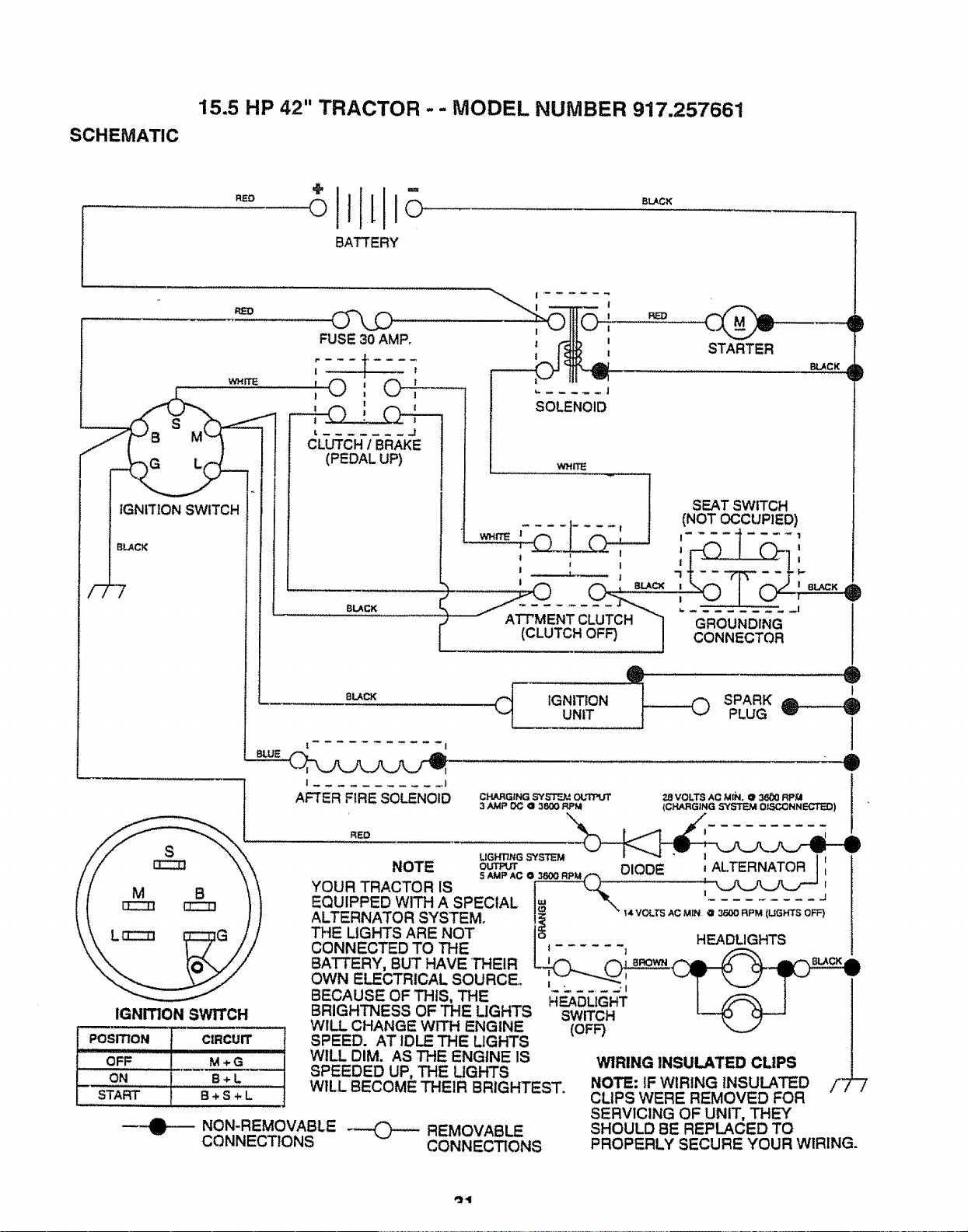
15.5 HP 42" TRACTOR - - MODEL NUMBER 917.257661
SCHEMATIC
RED
BATTERY
BLACK
/7
WHITE
IGNITION SWITCH
BLACK
FUSE 30 AMP,
t,
1
!
' O : O4-,'--
!
--I-O: r-,_z._
t _- J |
t j
CLUTCH I BRAKE
(PEDAL UP)
! I
_ ,.--jth I_-----_ _L._ STARTER aLAcx,
J
SOLENOID
wHrrE
BLACZ<
BLACK
INO O UP, O)
I I _ '
I I
,C UTC.O 1 CONN
@ @
IGNITION SPARK
UNIT PLUG
S
IGNITION SWITCH
POSITION CIRCUIT
OFF .............. M + G
ON B÷L
START B ÷ S ÷ L
I
AFTER FIRE SOLENOID
@
i
CHARGING SY,ET=J. = OLq'PUT 28 VOLTS AC MIN, @ 3600 RPM
3 AMP OC ,a 3600 RPM (CHARGING SYSTEM Ot.,,_::ONNECTED) ! "
I
NOTE sOAMU_ACe :3_ooRP.,-'x OIODE ' AL.TERNATOR t ',
YOUR TRACTOR IS _ _ __z "J '
EQUIPPED WITH A SPECIAL I.=. _ ......... J
ALTERNATOR SYSTEM. I_ " _4VOLTSAcMr. = 3r,ooaPM(UGH'rSOFF)
THE LIGHTS ARE NOT 1_ H_AnH_TS
CONNECTED TO THE I t ...... ; -- _"
BATTERY, BUT HAVETHEIR LJz_ _/-_lL-_ )__
OWN E_CTRICALSOURCEo ___ _ _ _1 _ v
BECAUSE OF THIS, THE !_E_ASI_i_I_ I /_, l
BRIGHTNESS OF THE LIGHTS SWITCH L_J_ _L__J
WILL CHANGE WITH ENGINE (OFF)
SPEED. AT IDLE THE LIGHTS
WILL DIM. AS THE ENGINE IS
SPEEDED UP, THE UGHTS
WILL BECOME THEIR BRIGHTEST.
NON-REMOVABLE _ REMOVABLE
CONNECTIONS CONNECTIONS
WIRING INSULATED CLIPS
NOTE: IF WIRING INSULATED /"_
CLIPS WERE REMOVED FOR
SERVICING OF UNIT, THEY
SHOULD BE REPLACED TO
PROPERLY SECURE YOUR WIRING.
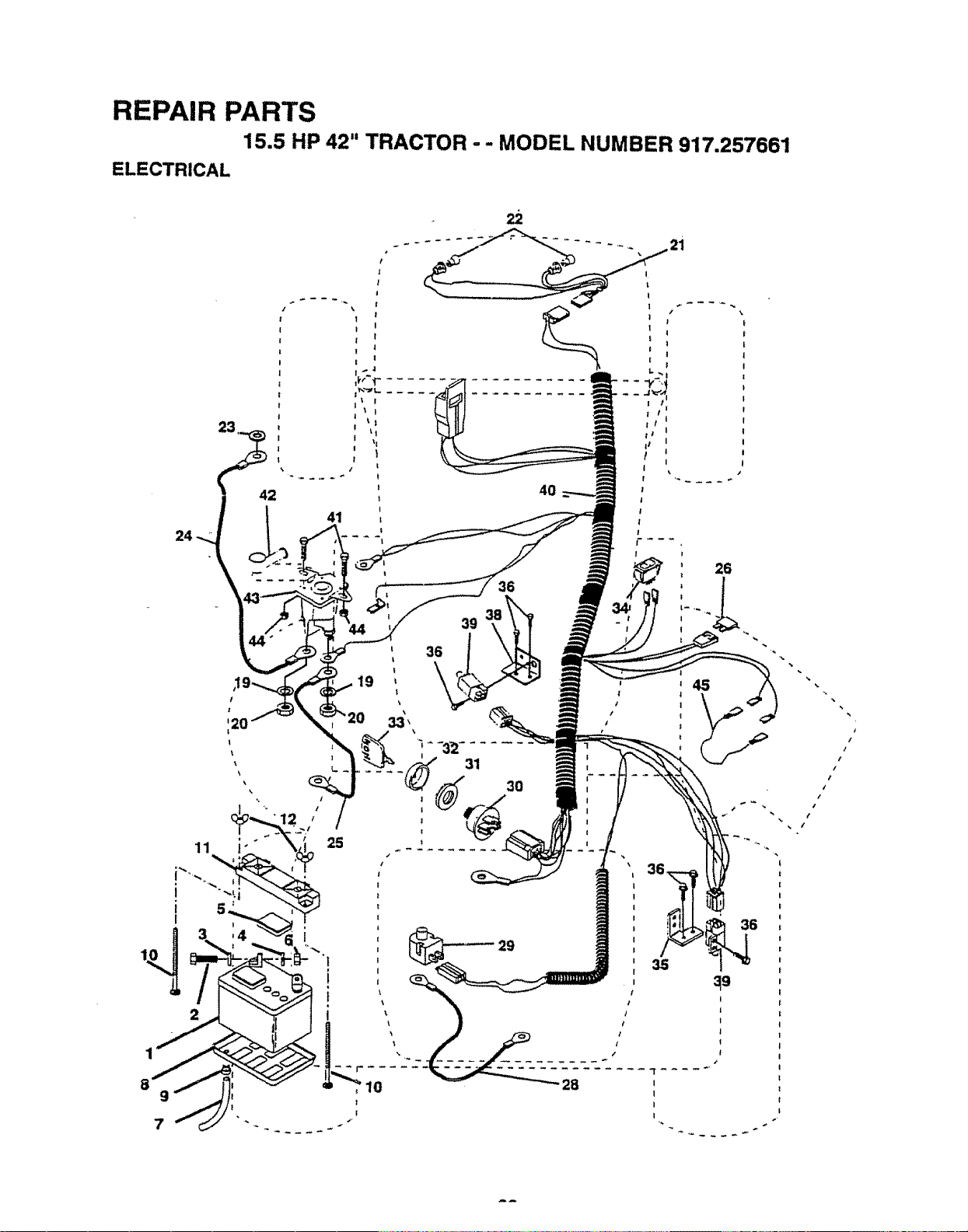
REPAIR PARTS
15.5 HP 42" TRACTOR - - MODEL NUMBER 917.257661
ELECTRICAL
24
23
42
19
l
/
25
3 ,,
4O
36
39 38%
\\ t
/
31
3O
45
26
29
36

REPAIR PARTS
15.5 HP 42" TRACTOR -- MODEL NUMBER 917,257661
ELECTRICAL
KEY PAA "
NO. NO. DESCRIPTION
1 121537X Battery
2 74760412 Bolt, Hex 1/4-20 UNC x 3/4
3 STD551025 Washer
4 STD551125 Washer
5 121264X Cap, Battery
6 STD541025 Nut
7 7697J Tube, Plastic
8 7603,,! Tray, Battery
9 109596X Clamp, Hose
10 STD532575 Bolt
11 102476X Guard, Terminal
12 123198X Nut, Plastic, Wing 1/4-20
19 STD551125 Washer, Lock
20 73350400 Nut, Hex, Jam 1/4-20 UNC
21 136850 Harness, Ught Socket
22 4152J Bulb, Light
23 11150400 Washer Lock Int. Tooth 1/4
24 420_J Cable, Battery
25 4206J Cable Batter,]
26 I08824X Fuse
28 4207J Cable, Ground
29 121305X Switch, Plunger
30 144921 Switch, Ignition
31 140400 Nut, Ignition
32 141226 Cover, IgnitionSwitch
33 140403 Key, Ignition
34 110712X Switch, Light
35 108236X Bracket, Switch
36 STD601005 Screw
38 140336 Bracket, Switch
39 109553X SwitCh, Interlock
40 140417 Harness, Ignition
41 71110408 Bolt BIk Fin Hex 1/4-20 UNC x 1/2
42 131563 Cover, Terminal
43 138406 Solenoid
44 73640400 Nut, Keps Blk Hex 1/4.20 UNC
45 140844 Adapter Ammeter Rectangular
NOTE: All component dimensions given in U.S. inches
1 inch = 25.4 mm
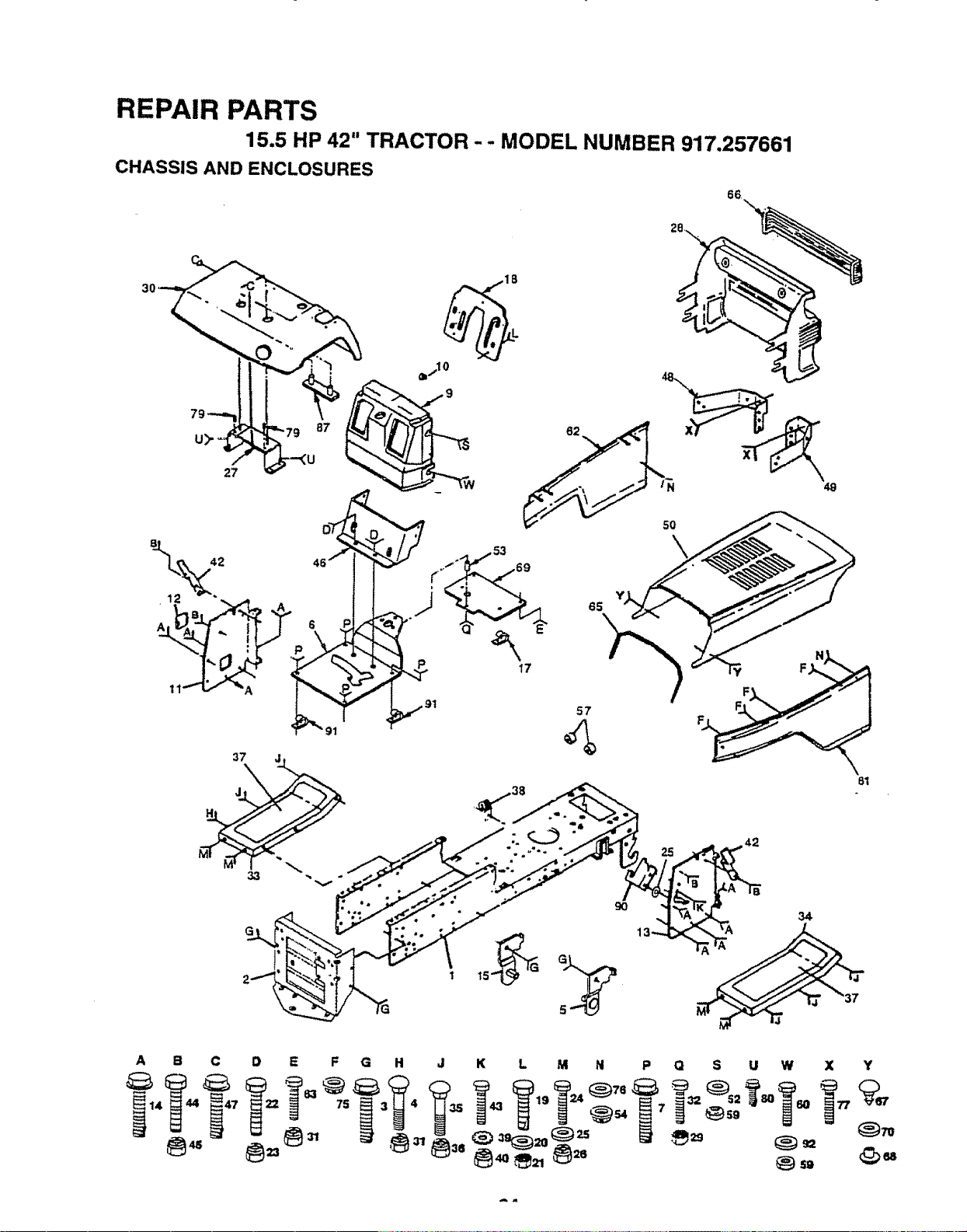
REPAIR PARTS
15.5 HP 42" TRACTOR - - MODEL NUMBER 917.257661
CHASSIS AND ENCLOSURES
66
57
A
B C D E F G H J K L M N P Q S U W X Y
4T Ts = 4 _. 6o
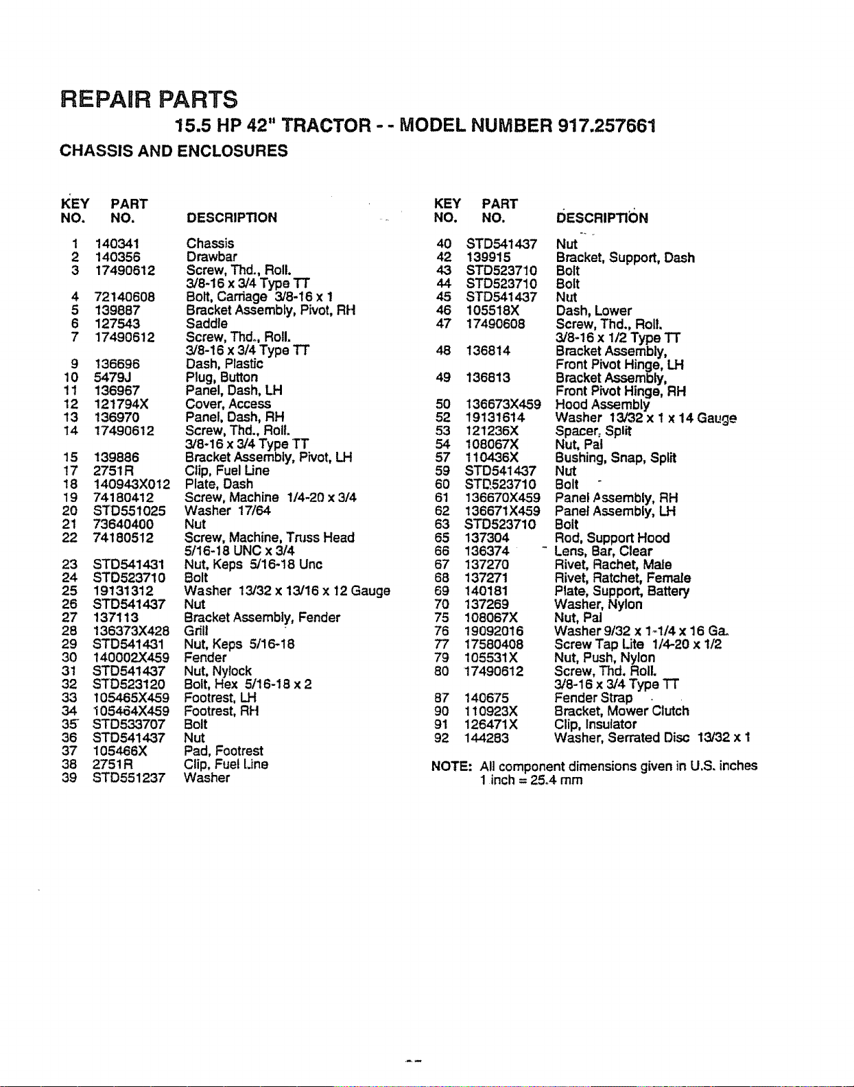
REPAIR PARTS
15.5 HP 42" TRACTOR - - MODEL NUMBER 917.257661
CHASSIS AND ENCLOSURES
KEY PART KEY PART
NO. NO. DESCRIPTION NO. NO. i_ESCRIPTI_)N
1
2
3
4
5
6
7
9
10
11
12
13
14
15
t7
18
19
20
21
22
23
24
25
26
27
28
29
30
31
32
33
34
35"
36
37
38
39
140341 Chassis 40
140356 Drawbar 42
17490612 Screw, Thd., Roll. 43
3/8-16 x 3/4 Type TT 44
72140608 Bolt, Carriage 3/8-16 x 1 45
139887 Bracket Assembly, Pivot, RH 46
127543 Saddle 47
17490612 Screw, Thdo, Roll.
3/8-16 x 314Type TT 48 136814
t36696 Dash, Plastic
547_J Plug, Button 49 136813
136967 Panel, Dash, LH
121794X Cover, Access 50 136673X459
136970 Panel, Dash, RH 52 19131614
17490612 Screw, Thd., Roll. 53 121236X
3/8-16 x 3/4 Type TT 54 108067X
139886 Bracket Assembly, Pivot, LH 57 110436X
2751R Clip, Fuel Line 59 STD541437
140943X0t2 Plate, Dash 60 STD523710
74180412 Screw, Machine 1/4-20 x 3/4 61 136670X459
STD551025 Washer 17/64 62 136671X459
73640400 Nut 63 STD523710
74180512 Screw, Machine, Tress Head 65 137304
5/16-18 UNC x 3/4 66 136374 -
STD5414-31 Nut, Keps 5/16-18 Unc 67 137270
STD523710 Bolt 68 137271
19131312 Washer 13/32x 13/16x 12 Gauge 69 140181
STD541437 Nut 70 137269
13'7113 Bracket Assembly, Fender 75 108067X
136373X428 Grill 76 19092016
STD541431 Nut, Keps 5t16-18 77 17580408
140002X459 Fender 79 105531X
STD541437 Nut. Nylock 80 17490612
STD523120 Bolt, Hex 5/16-18 x 2
105485X459 Footrest, LH 87 1406'75
I05464X459 Footrest, RH 90 110923X
STD533707 Bolt 91 126471X
STD541437 Nut 92 144283
105466X Pad, Footrest
2751R Clip, Fuel Line
STD65123'7 Washer
STD541437 Nut ....
139915 Bracket, Support, Dash
STD523710 Bolt
STD523710 Bolt
STD5414-37 NUt
105518X Dash, Lower
17490608 Screw, Thd., Roll.
3/8-16 x 1/2 Type TT
Bracket Assembly,
Front Pivot Hinge, LH
Bracket Assembly,
Front Pivot Hinge, RH
Hood Assembly
Washer 13/32 x I x 14 Gauge
Spacer, Split
Nut, Pal
Bushing, Snap, Split
Nut
Bolt
Panel Assembly, RH
Panel Assembly, LH
Bolt
Rod, Support Hood
Lens, Bar, Clear
Rivet, Rachet, Mate
Rivet, Ratchet, Female
Plate, Support, Battery
Washer, Nylon
Nut, Pal
Washer 9/32 x 1_1/4 x 16 Ga.
Screw Tap Lite 1/4-20 x 1/2
Nut, Push, Nylon
Screw, Thd. Roll
3/8-16 x 3/4 Type TT
Fender Strap _
Bracket, Mower Clutch
Clip, Insulator
Washer, Serrated Disc 13/32 x I
NOTE: All component dimensions given in U.S. inches
1 inch = 25.4 mm
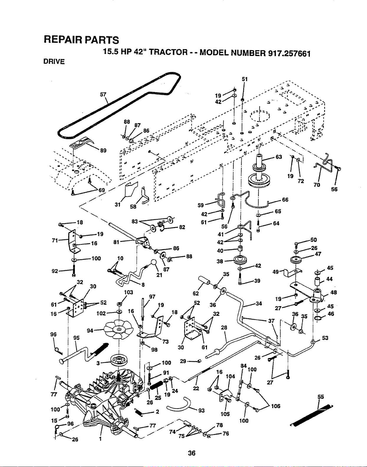
REPAIR PARTS
15.5 HP 42" TRACTOR" "MODEL NUMBER 917.257661
26
22 55
2_
100
O6
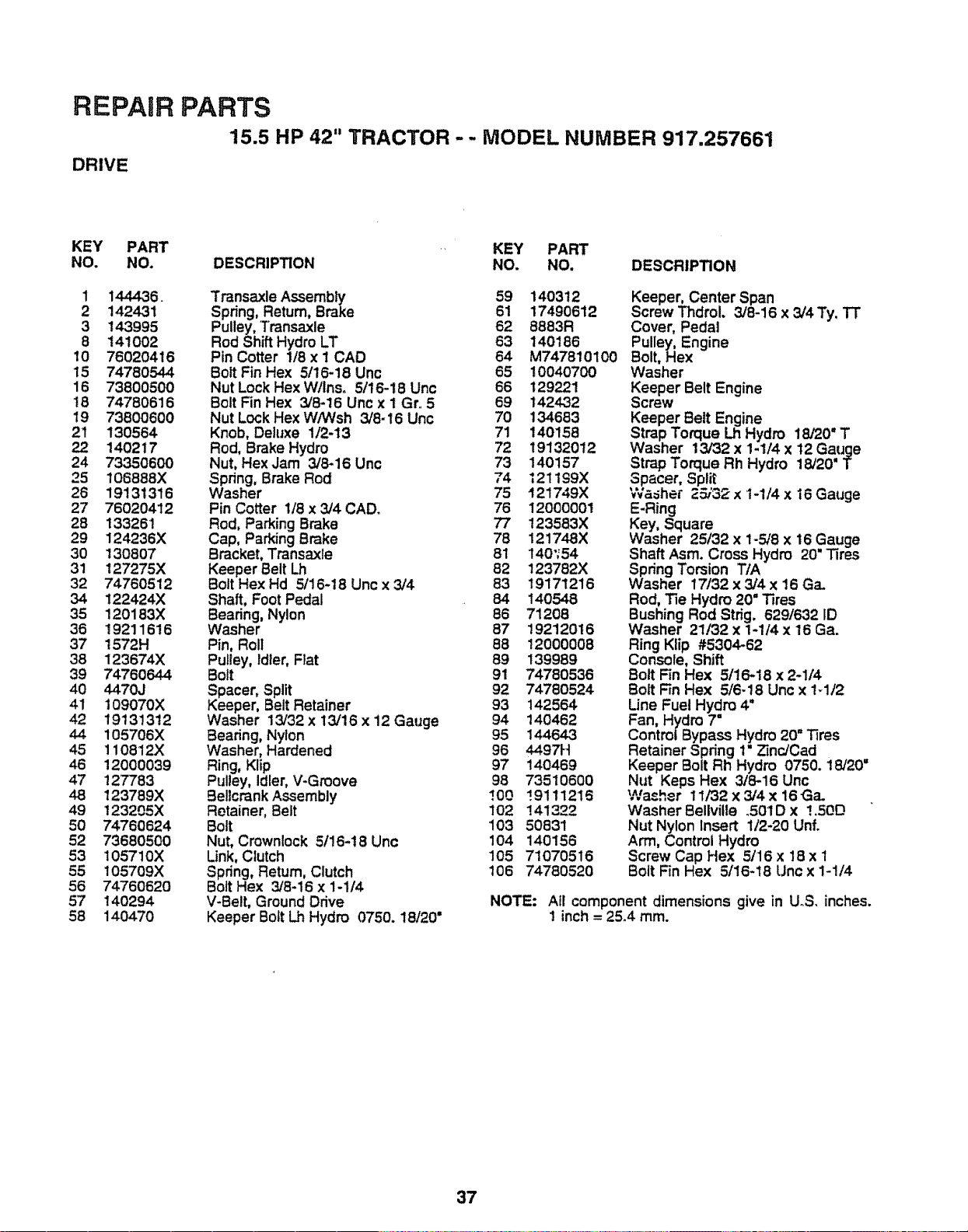
REPAIR PARTS
15.5 HP 42" TRACTOR - - MODEL NUMBER 917.257661
DRIVE
KEY PART KEY PART
NO. NO. DESCRIPTION NO. NO. DESCRIPTION
1 144436. Transaxle Assembly 59 140312
2 1424.31 Spring, Return, Brake 61 17490612
3 143995 Pulley, Transaxle 62 8883R
8 141002 Rod Shift Hydro LT 63 140186
10 76020416 Pin Cotter 1/8 x I CAD 64 M747810100
15 74780544 Bolt Fin Hex 5/16-18 Unc 65 10040700
16 73800500 Nut Lock Hex Wllns. 5/16-18 Unc 66 129221
t8 74780616 Bolt Fin Hex 3/8-t6 Unc x 1 Gr,.5 69 142432
19 73800600 Nut Lock Hex WiWsh 3/8-16 Unc 70 134683
21 130564 Knob, Deluxe 1/2-13 71 140158
22 140217 Rod, Brake Hydro 72 19132012
24 73350600 Nut, Hex Jam 3/8-16 Unc 73 140157
25 106888X Spring, Brake Rod 74 121199X
26 19131316 Washer 75 121749X
27 76020412 Pin Cotter 1/8 x 3/4 CAD. 76 12000001
28 133261 Rod, Parking Brake 77 123583X
29 124236X Cap, Parking Brake 78 121748X
30 130807 Bracket, Transaxle 81 140',54
31 127275X Keeper Belt Lh 82 123782X
32 74760512 Bolt Hex Hd 5116-18 Unc x 3/4 83 19171216
34 122424X Shaft, Foot Pedal 84 140548
35 120183X Beating, Nylon 86 71208
36 19211616 Washer 87 19212016
37 1572H Pin, Roll 88 12000008
38 123674X Pulley, Idler, Flat 89 139989
39 74760644 Bott 91 74780536
40 4470J Spacer, Split 92 74780524
41 109070X Keeper, Belt Retainer 93 142564
42 19131312 Washer 13/32 x 13/16 x i2 Gauge 94 140462
44 105706X Beadng, Nylon 95 144643
45 110812X Washer, Hardened 96 4497H
46 12000039 Ring, Klip 97 140469
47 127783 Pulley, Idler, V-Groove 98 73510600
48 123789X Bellcrank Assembly !00 _9111216
49 !23205X Retainer, Belt 102 141322
50 74760624 Bolt 103 50831
52 73680500 Nut, Crownlock 5/16-18 Unc 104 140156
53 105710X Link,Clutch 105 71070516
55 105709X Spdng, Return, Clutch 106 74780520
56 74760620 Bolt Hex 3/8-16 x 1-1/4
57 140294 V-Belt, Ground Drive
58 140470 Keeper Bolt Lh Hydro 0750. 18120"
Keeper, Center Span
Screw Thdrol. 3/8-16 x 3/4 Ty. TT
Cover, Pedal
Pulley, Engine
Bolt, Hex
Washer
Keeper Belt Engine
Screw
Keeper Belt Engine
Strap Torque Lh Hydro 18/20" T
Washer 13/32 x 1-1/4 x 12 Gauge
Strap Torque Rh Hydro 18/20" T
Spacer, Split
Washer 25/'32 x 1-1t4 x 16 Gauge
E-Ring
Key, Square
Washer 25132 x 1-5/8 x 16 Gauge
Shaft Asm. Cross Hydro 20" Tires
Spring Torsion TIA
Washer 17/32 x 3/4 x 16 Ga.
Rod, Tie Hydro 20=Tires
Bushing Rod Strig. 629/632 ID
Washer 21/32 x 1-1/4 x 16 Ga.
Ring Klip #5304-62
Console, Shift
Bolt Fin Hex 5t16-18 x 2-1/4
Bolt Ffn Hex 5/6-18 Unc x 1-t12
Line Fuel Hydro 4"
Fan, Hydro 7"
Control Bypass Hydro 20" Tires
Retainer Spring 1" Zinc/Cad
Keeper Bolt Rh Hydro 0750. 18/20"
Nut Keps Hex 3/8-16 Unc
Washer 11/32 x 3/4 x 16Ga.
Washer Beliville .501D x 1,50D
Nut Nylon Insert 112-20 Unf.
Arm, Control Hydro
Screw Cap Hex 5116x 18 x 1
Bolt Fin Hex 5/16-18 Unc x 1-114
NOTE: Afl component dimensions give in UoS. inches.
1 inch = 25.4 ram.
37
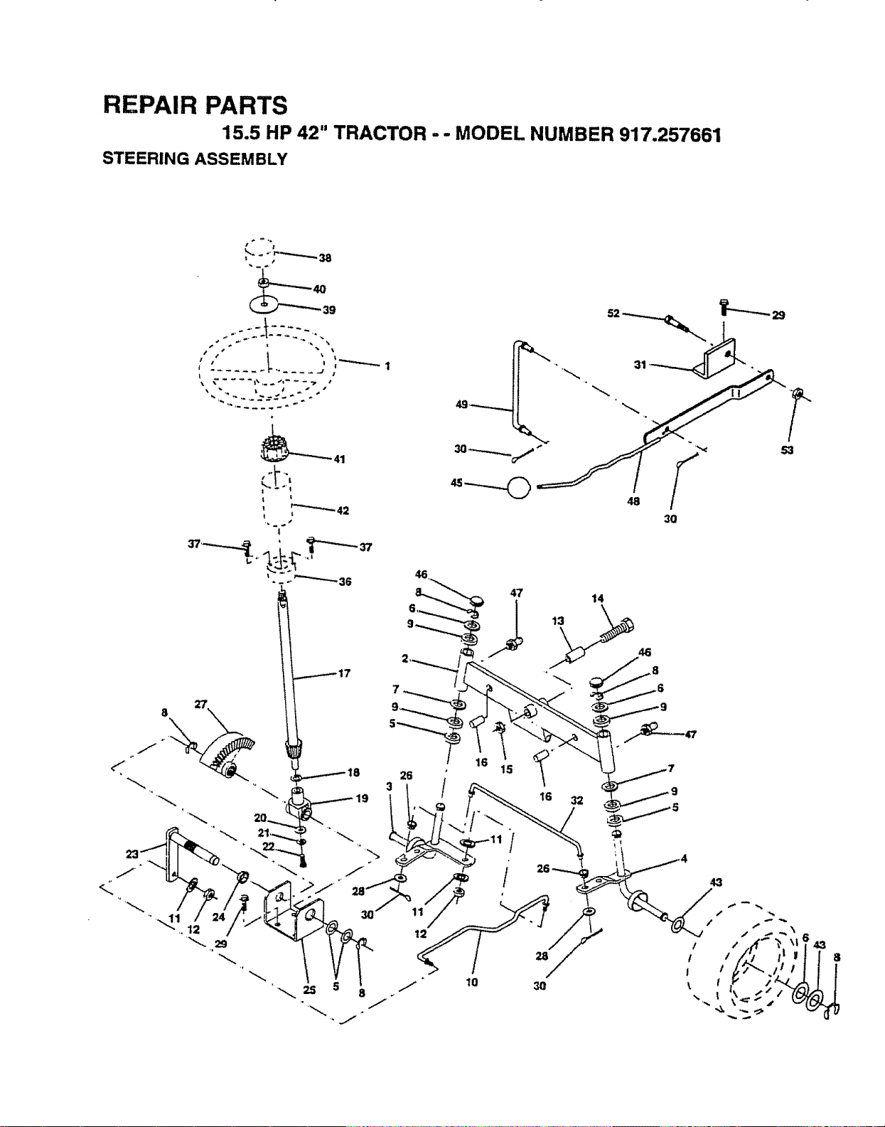
REPAIR PARTS
15.5 HP 42" TRACTOR ..- MODEL NUMBER 917.257661
STEERING ASSEMBLY
t s
39
,'" -i
t t
I
t
l
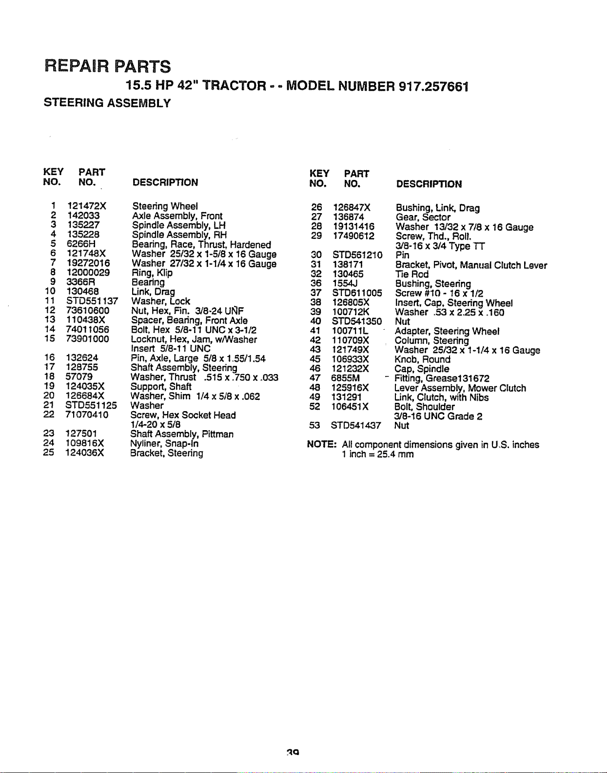
REPAIR PARTS
15.5 HP 42" TRACTOR -- MODEL NUMBER 917,257661
STEERING ASSEMBLY
KEY PART KEY PART
NO. NO. DESCRIPTION NO. NO, DESCRIPTION
1 121472X
2 142033
3 135227
4 135228
5 6266H
6 121748X
7 19272016
8 12000029
9 3366R
10 130468
11 STD551137
12 73610600
13 110438X
14 74011056
15 73901000
16 132624
17 128755
18 57079
19 124035X
20 126684X
21 STD551125
22 71070410
23 127501
24 I09816X
25 124036X
Steering Wheel 26 126847X
Axle Assembly, Front 27 136874
Spindle Assembly, LH 28 19131416
Spindle Assembly, RH 29 17490612
Bearing, Race, Thrust, Hardened
Washer 25/32 x 1-5/8 x 16 Gauge 30 STD561210
Washer 27/32 x 1-1/4 x 16 Gauge 31 138171
Ring, Klip 32 130465
Bearing 36 1554J
Link, Drag 37 STD611005
Washer, Lock 38 126805X
Nut, Hex, Fin. 3/8_24 Ut_F 39 t00712K
Spacer, Bearing, Front Axle 40 STD541350
Bolt, Hex 5/8-11 UNCx3-1/2 41 100711L
Locknut, Hex, Jam, w/W'asher 42 110709X
Insert 5/8-11 UNC 43 121749X
Pin, Axle, Large 5/8 x 1.55/1.54 45 106933X
Shaft Assembly, Steering 46 121232X
Washer, Thrust .515 x .750 x _033 47 6855M -
Support, Shaft 48 t25916X
Washer, Shim 1/4 x 5/8 x .062 49 131291
Washer 52 106451X
Screw, Hex Socket Head
1/4-20 x 5t8 53 STD541437
Shaft Assembly, Pittman
Nyliner, Snap-In
Bracket, Steering
Bushing, Link, Drag
Gear, Sector
Washer 13/32 x 7/8 x 16 Gauge
Screw, Thd., Roll.
3/8-16 x 3/4 Type TT
Pin
Bracket, Pivot, Manual Clutch Lever
Tie Rod
sBUShing,Steering
crew #10 - 16 x 1/2
Insert, Cap, Steering Wheel
Washer .53 x 2.25 x .160
NUt
Adapter, Steering Wheel
Column, Steering
Washer 25132 x 1-1/4 x 16 Gauge
Knob, Round
Cap, Spindle
Fitting, Grease131672
Lever Assembly, Mower Clutch
Link, Clutch, with Nibs
Bolt, Shoulder
3/8-16 UNC Grade 2
Nut
NOTE: All component dimensions given in U.S. inches
1 inch = 25.4 mm
.qQ
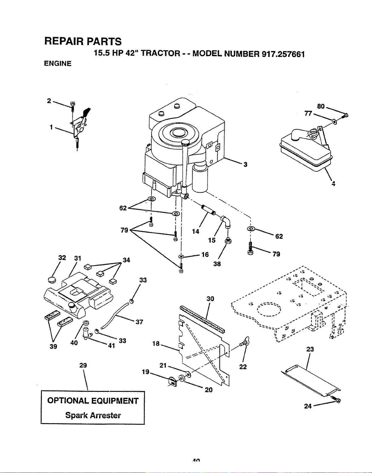
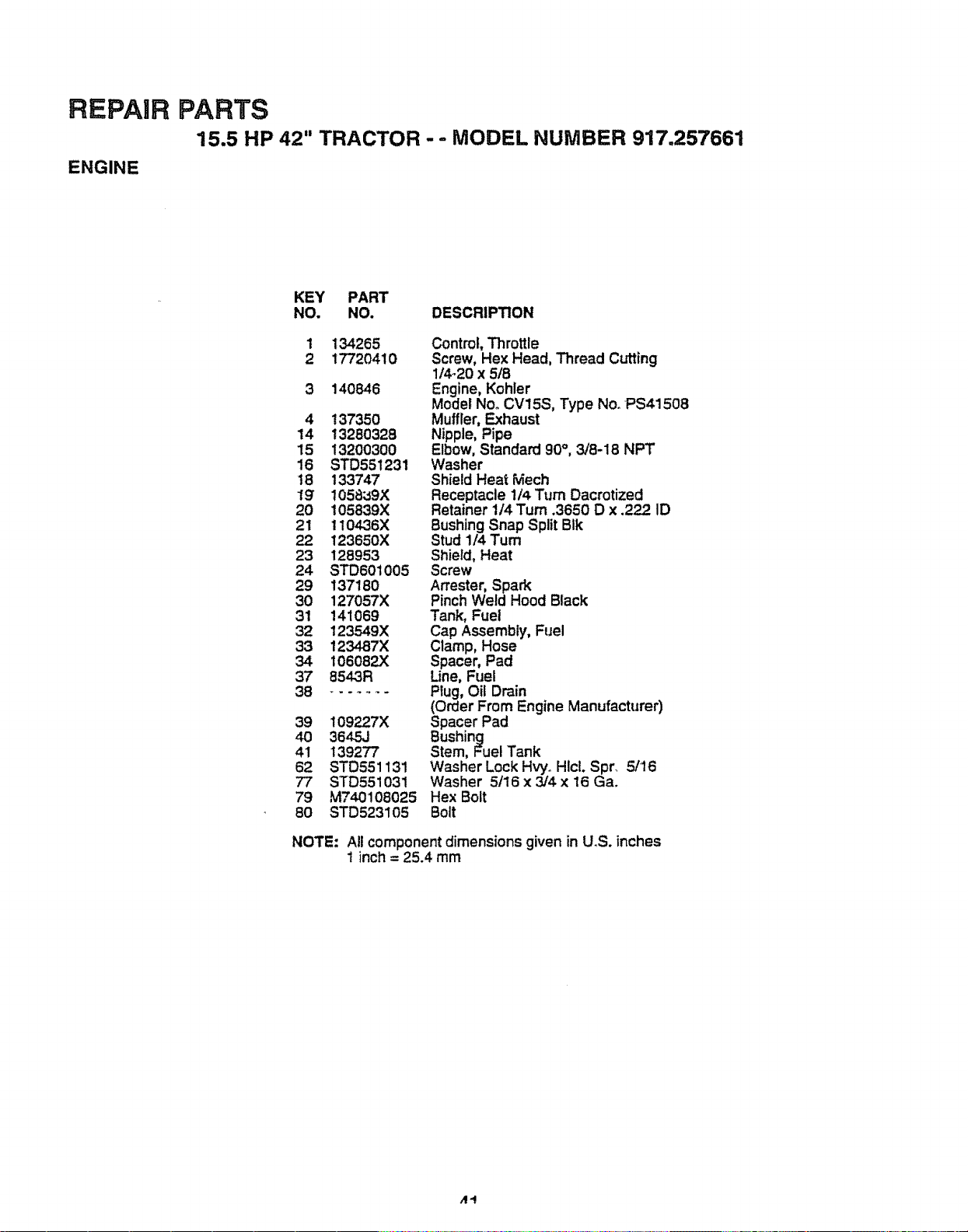
REPAIR
ENGINE
PARTS
15,5 HP 42" TRACTOR - - MODEL NUMBER 917,257661
KEY PART
NO. NO. DESCRIPTION
1 134265 Control, Throttle
2 17720410 Screw, Hex Head, Thread Cutting
1/4_20x 5/8
3 140846 Engine, Kohler
Model No. CV15S, Type NooPS41508
4 137350 Muffler, Exhaust
14 13250328 Nipple, Pipe
15 13200300 Elbow, Standard 90°, 3/8-18 NPT
16 STD551231 Washer
18 133747 Shield Heat Mech
19" 1058;_9X Receptacle 1/4 Turn Dacrotized
20 105839X Retainer 1/4 Turn .3650 D x .222 ID
21 1104-36X Bushing Snap Split BIk
22 123650X Stud 1/4 Turn
23 128953 Shield, Heat
24 STD601005 Screw
29 137180 An'ester, Spark
30 127057X Pinch Weld Hood Black
31 141069 Tank, Fuel
32 123549X Cap Assembly, Fuel
33 123487X Clamp, Hose
34 I06082X Spacer, Pad
37 8543R Line, Fuel
38 ........ Plug, Oil Drain
(Order From Engine Manufacturer)
39 109227X Spacer Pad
40 3645J Bushing
41 139277 Stem, Fuel Tank
62 STD551131 Washer Lock HvyoHIcL Spr. 5/16
77 STD551031 Washer 5/16 x 3/4 x 16 Ga.
79 M740108025 HexBolt
80 STD523105 Bolt
NOTE: All component dimensions given in U.S. inches
1 inch = 25.4 mm
,,14
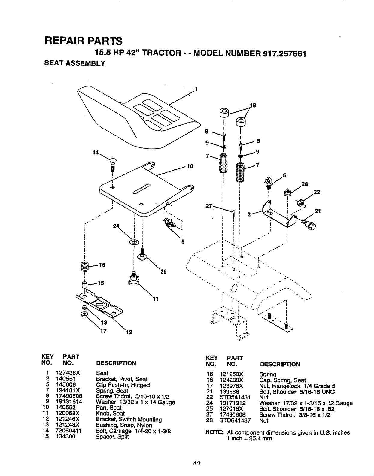
REPAIR PARTS
15.5 HP 42" TRACTOR -- MODEL NUMBER 917.257661
SEAT ASSEMBLY
14
i t
i ,_I s
25
%
12
i ! 1 i. _ `''+ !
,, , t rL ". I
! ,r"1.... ,,' ,' .-"i
%
iw,++ _.+ _++
KEY
NO.
1
2
5
7
8
9
10
1'1
12
13
14
15
PART
NO.
127438X
140551
145006
124181X
1749O508
19131614
140552
120068X
121246X
121248X
720504'11
134.300
DESCRIPTION
Seat
Bracket, Pivot, Seat
Clip Push-In, Hinged
Spdng, Seat
Screw Thdrol,5116-18 x 1/2
Washer 13/32 x I x 14 Gauge
Pan, Seat
Knob, Seat
Bracket, Switch Mounting
Bushing, Snap, Nylon
Bolt, Carriage 1/4-20 x 1-3/8
Spacer, Split
KEY PART
NO. NO. DESCRIPTION
16 121250X
18 124238X
17 123976X
21 139888
22 STD541431
24 19171912
25 127018X
27 17490608
28 STO,541437
Spring _ .
Cap, Spring, Seat
Nut, Flangelock I/4 Grade 5
Bolt,Shoulder 5/16-18 UNC
Nut
"Washer 17/32 x 1-3/16 x 12 Gauge
Bolt, Shoulder 5/16-t8 x ,62
Screw ThdmL 3/8-16 x 1/2
NUt
NOTE: All component dimensions given in U.S. inches
1 inch = 25.4 mm
/1'3
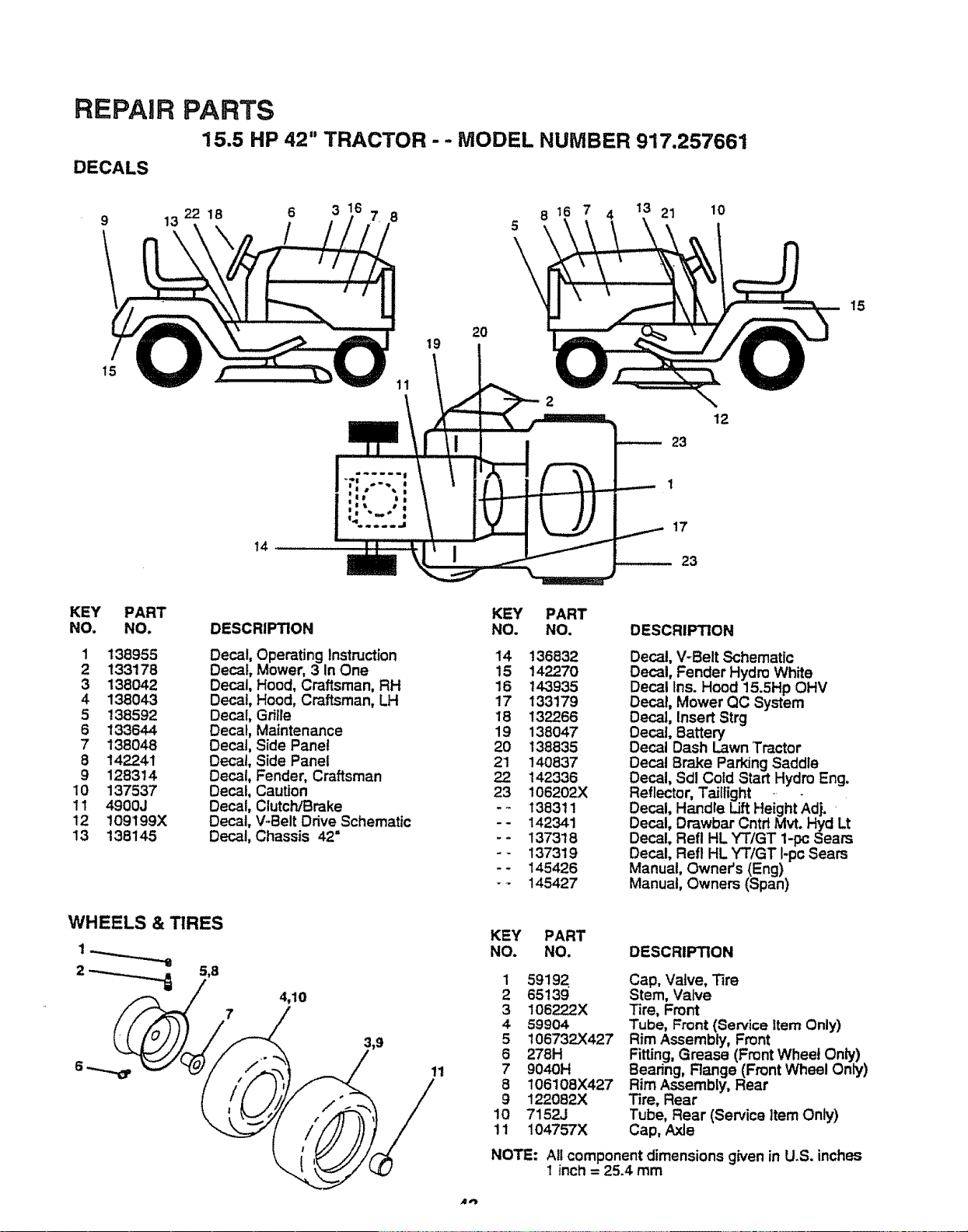
REPAIR
DECALS
15
PARTS
15.5 HP 42" TRACTOR -- MODEL NUMBER 917.257661
13
2218
6
/
7 8
11
19
2O
5
\
21 10
23
12
15
14
17
23
KEY PART
NO, NO.
1 138955
2 133178
3 138042
4 138043
5 138592
6 133644
7 138048
8 14_41
9 128314
10 137537
11 49QOJ
12 109199X
13 138145
DESCRIPTION
Decal,
Decal,
Decal,
Decal
Decal
Decal
Decal
Decal
Decal
Decal
Decal
Decal
Decal
KEY PART
NO. NO. DESCRIPTION
Operating Instruction 14 136832
Mower, 3 In One 15 14_-_70
Hood, Craftsman, RH 16 143935
Hood, Craftsman, LH 17 133179
Grille 18 132266
Maintenance 19 138047
Side Panel 20 138835
Side Panel 21 !40837
Fender, Craftsman _ 142336
Caution 23 !06202X
ClutctVBrake - _ 138311
V-Belt Ddve Schematic - - 142341
Chassis 42= -- 137318
- - 137319
-- 145426
- - 145427
Decal, V-Belt Schematic
Decal, Fender Hydro White
Decal Ins. Hood 15.5Hp OHV
Decal, Mower QC System
Decal, Insert Strg
Decal, Battery
Decal Dash Lawn Tractor
Decal Brake Parking Saddle
Decal, Sdl Cold Start Hydro Eng.
Reflector, Taillight
Decal, Handle Lift Height Adj.
Decal, Drawbar Cntd Mvt. Hyd Lt
Decal, Refl HL YT/GT 1-pc Sears
Decal, Refl HL YTIGT I-pc Sears
Manual, Owner's (Eng)
Manual, Owners (Span)
WHEELS & TIRES
4,10
11
KEY PART
NO. NO. DESCRIPTION
1 59192 Cap, Valve, Tire
2 65139 Stem, Valve
3 106222X Tile, Front
4 59904 Tube, Front (Service Item Only)
5 t06732X427 Rim Assembly, Front
6 278H Fitting, Grease (Front Wheel Only)
7 9040H Bearing, Range (Front Wheel Only)
8 106108X427 Rim Assembly, Rear
9 122082X Tire, Rear
10 7152J Tube, Rear (Service item Only)
11 104757X Cap, Axle
NOTE:
All component dimensions given in U.S. inches
t inch = 25.4 mm
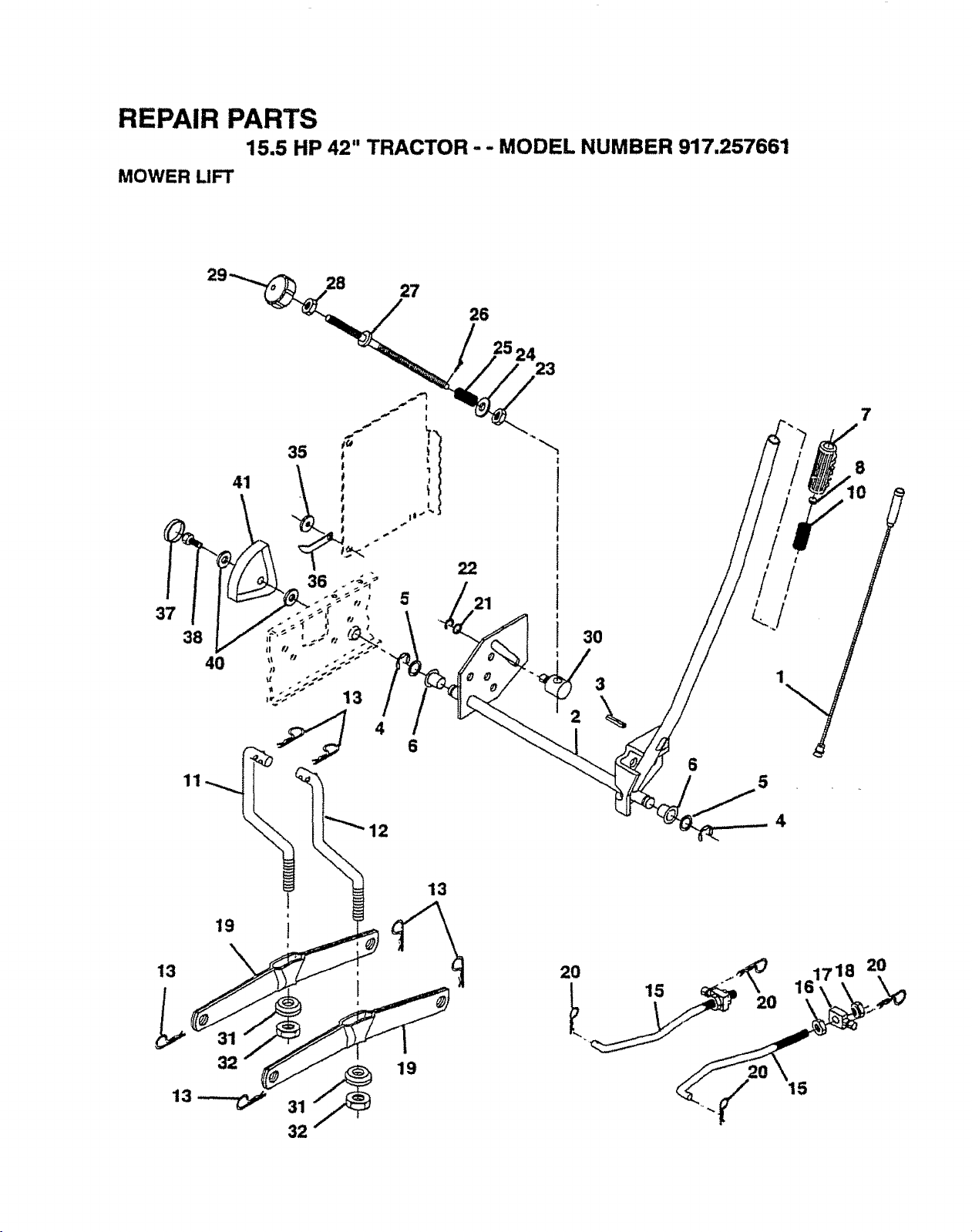
REPAIR PARTS
15.5 HP 42" TRACTOR - - MODEL NUMBER 917.257661
MOWER LIFT
4 6
11
3O
\
6
7
8
10
4
19
13
32
13_
31 _ 19
32
13
2O
15
2O
161718
2O
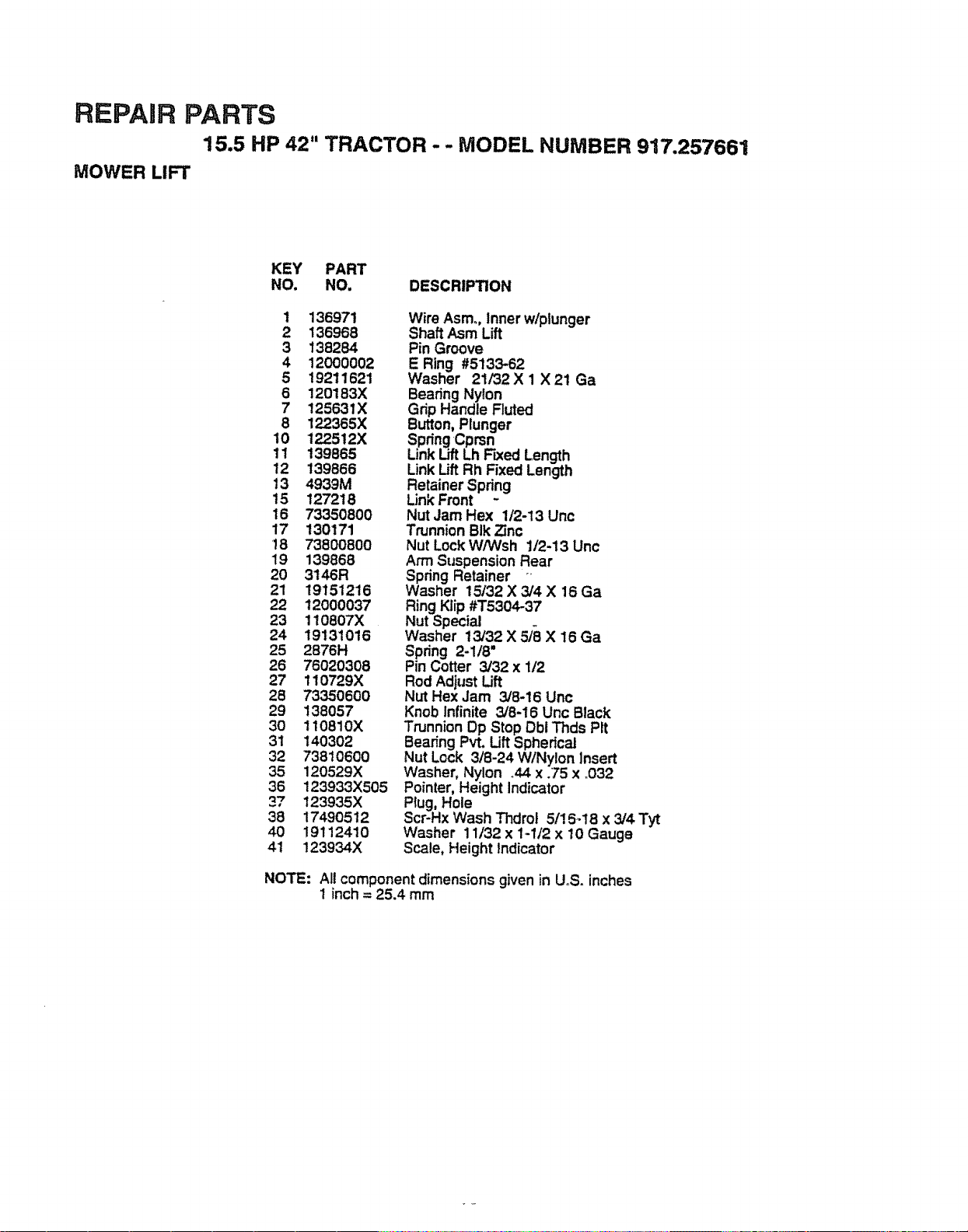
REPAIR PARTS
15.5 HP 42" TRACTOR -- MODEL NUMBER 917.257661
MOWER LIFT
KEY PART
NO. NO. DESCRIPTION
1 136971
2 136968
3 138284
4 12000002
5 19211621
6 120183X
7 125631X
8 122365X
10 122512X
11 139865
12 139866
13 4939M
t5 127218
16 73350800
17 130171
18 73800800
19 139868
20 3146R
21 19151216
22 12000037
23 110807X
24 19131016
25 2876H
26 76020308
27 110729X
28 73350600
29 138057
30 110810X
31 140302
32 73810600
35 120529X
36 123933X505
37 123935X
38 17490512
40 19'112410
41 123934X
Wire Asm., Inner w/plunger
Shaft Asm Lift
Pin Groove
E Ring #5133-62
Washer 21/32 X 1 X 21 Ga
Bearing Nylon
Grip Handle Fluted
Button, Plunger
Spring Cprsn
Link Lift Lh FLxedLength
Link LiftRh Fixed Length
Retainer Spring
Link Front -
Nut Jam Hex 1/2-13 Unc
Trunnion BIk Zinc
Nut Lock WiWsh 1/2-13 Unc
Arm Suspension Rear
Spring Retainer
Washer 15/32 X 3/4 X 16 Ga
Ring Klip #T5304-37
Nut Special
Washer 13132 X 5/8 X 16 Ga
Spring 2-1t8"
Pin Cotter 3132x 1/2
Rod AdjustLift
Nut Hex Jam 3/8-16 Unc
Knob Infinite 3/8-16 Unc Black
Trunnion Dp Stop Dbt Tnds Pit
Bearing Pvt. Lift Spherical
Nut Lock 3/8-24 WlNylon Insert
Washer, Nylon °44 x .75 x .032
Pointer, Height indicator
Plug, Hole
Scr-Hx Wash Thdrol 5/18-18 x 3/4 Tyt
Washer 11/32 x 1-1/2 x 10 Gauge
Scale, Height Indicator
NOTE: All component dimensions given in UoS.inches
1 inch = 25.4 mm
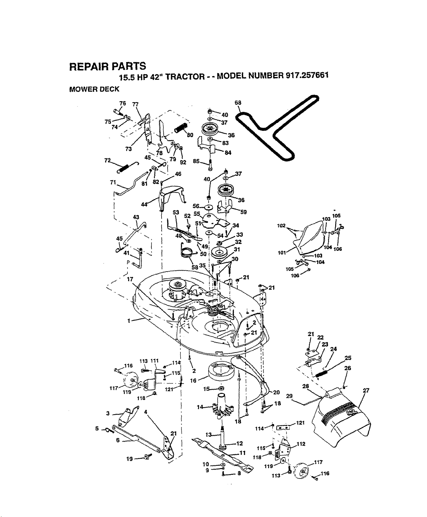
REPAIR PARTS
15,5 HP 42" TRACTOR - .. MODEL NUMBER 917,257661
MOWER DECK
33
32
31
101_
16
29
27
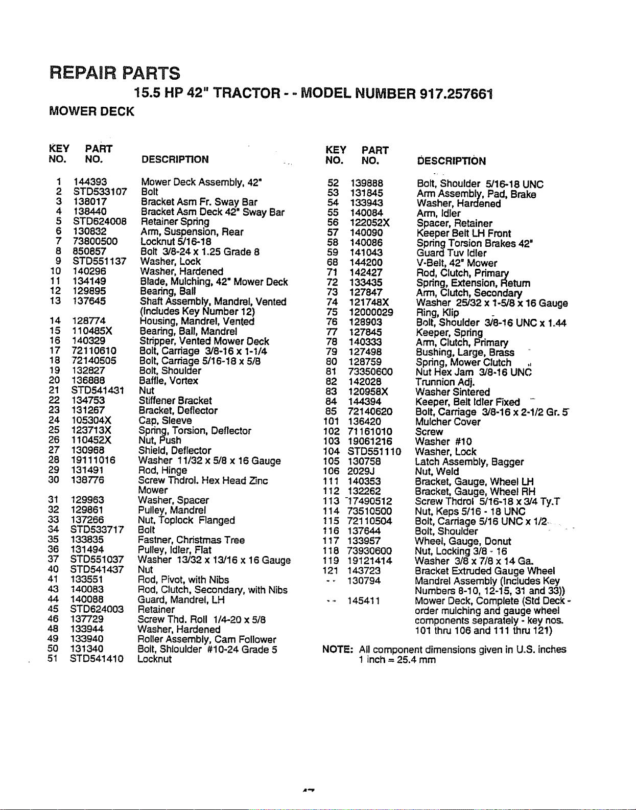
REPAIR PARTS
15.5 HP 42" TRACTOR -., MODEL NUMBER 917.257661
MOWER DECK
KEY PART KEY PART
NO. NO. DESCRIPTION ..... NO. NO, DESCRIPTION
1 144393
2 STD533107
3 138017
4 138440
5 STD624008
6 130832
7 73800500
8 850857
9 STD551137
10 t40296
11 134149
12 129895
13 137645
14 128774
15 110485X
16 140329
17 72110610
18 72140505
19 132827
20 136888
21 STD541431
22 134753
23 131267
24 105304X
25 123713X
26 110452X
27 130968
28 19111016
29 131491
30 138776
31 129963
32 129861
33 137266
34 STD533717
35 t33835
36 131494
37 STD551037
40 STD541437
41 133551
4.3 140083
44 140088
45 STD624003
46 137729
48 133944
49 133940
50 131340
51 STD541410
Mower Deck Assembly, 42" 52 139888
Bolt 53 131645
Bracket Asm Fr. Sway Bar 54 133943
BracketAsm Deck 42" Sway Bar 55 140084
Retainer Spring 56 122052X
Arm, Suspension, Rear 57 140090
Locknut 5/16-18 58 140086
Bolt 3/8-24 x 1_25Grade 8 59 141043
Washer, Lock 68 144200
Washer, Hardened 71 142427
Blade, Mulching, 42" Mower Deck 72 133435
Beadng, Ball 73 127847
Shaft Assembly, Mandrel, Vented 74 121748X
(includes Key Number 12) 75 12000029
Housing, Mandrel, Vented 76 128903
Bearing, Ball, Mandrel 77 127845
Stripper, Vented Mower Deck 78 140333
Bolt,Carriage 3/8-16 x 1-114 79 127498
Bolt, Carriage 5/16-18 x 5/8 80 128759
Bolt,Shoulder 81 73350600
Baffle, Vortex 82 142028
Nut 83 120958X
Stiffener Bracket 84 144394
Bracket, Deflector 85 72140620
Cap, Sleeve 101 136420
Spring, Torsion, Deflector 102 71161010
Nut, Push 103 19061216
Shield, Deflector 104 STD551110
Washer 11/32x 5/8 x 16 Gauge 105 130758
Rod, Hinge 106 2029J
Screw Thdrot. Hex Head 23nc 111 140353
Mower 112 !32262
Washer, Spacer 113 -17490512
Pulley, Mandrel 114 73510500
Nut, Toptock Flanged 115 72110504
Bolt 116 137644
Fastner, Christmas Tree 117 133957
Pulley, Idler, Flat 118 73930600
Washer 13/32x 13/16 x16 Gauge 119 19121414
Nut 121 143723
Rod, Pivot, with Nibs - - 130794
Rod, Clutch, Secondary, with Nibs
Guard, Mandrel, LH -.- 145411
Retainer
Screw Thd. Roll 1/4-20 x 5/8
Washer, Hardened
Roller Assembly, Cam Follower
Bolt, Shloulder #10-24 Grade 5
Locknut
Bolt, Shoulder 5/16-18 UNC
Arm Assembly, Pad, Brake
Washer, Hardened
Arm, Idler
Spacer, Retainer
Keeper Belt LH Front
Spring Torsion Brakes 42"
Guard Tuv Idler
V-Belt, 42 =Mower
Rod, Clutch, Pdmary
Spring, Extension, Return
Arm, Clutch, Secondary
Washer 25/32 x 1-5/8 x t6 Gauge
Ring, Klip
Bolt, Shoulder 3/6-!6 UNC x 1.44
Keeper, Spring
Arm, Clutch, Primary
Bushing, Large, Brass _'
Spring, Mower Clutch .,
Nut Hex Jam 3/8.16 UNC
Trunnion Adj.
Washer Sintered
Keeper, Belt Idler Fixed -
Bolt, Carriage 3/8-16 x 2-1/2 Gr. 5"
Mulcher Cover
Screw
Washer #10
Washer, Lock
Latch Assembly, Bagger
Nut, Weld
Bracket, Gauge, Wheel LH
Bracket, Gauge, Wheel RH
Screw Thdrol 5/16-18 x 3/4 Ty.T
Nut, Keps 5/16 - t8 UNC
Bolt, Carriage 5/16 UNC x 1/2....
Bolt, Shoulder
Wheet, Gauge, Donut
Nut, Locking 3/8 _ 16
Washer 3/8 x '7/8 x 14 Ga.
Bracket Extruded Gauge Wheel
Mandrel Assembly (Includes Key
Numbers 8-10, 12-15, 31 and 33))
Mower Deck, Complete (Std Deck -
order mulching and gauge wheel
components separately - key nos.
101 thru 106 and 111 thru 121)
NOTE: All component dimensions given in U.S. inches
1 inch = 25.4 mm
_l,-y
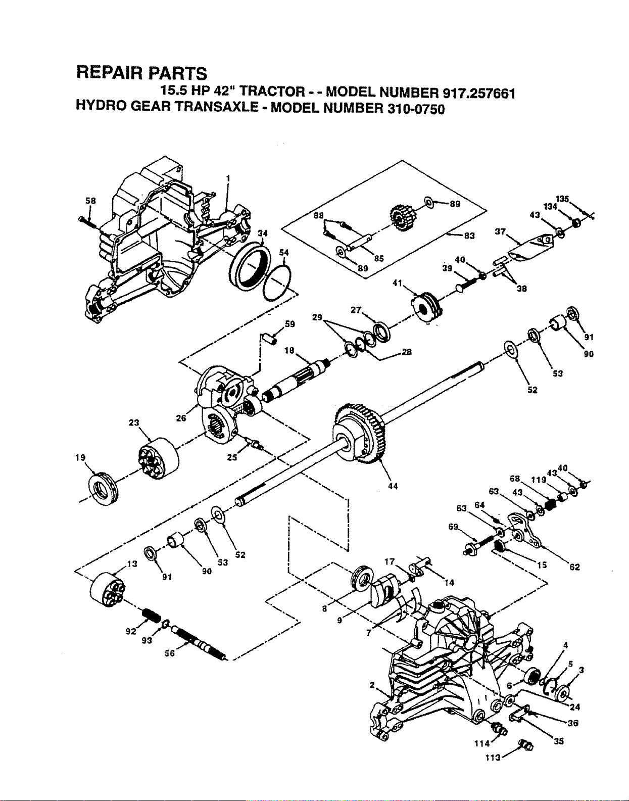
REPAIR PARTS
15.5 HP 42" TRACTOR-- MODEL NUMBER 917.257661
HYDRO GEAR TRANSAXLE - MODEL NUMBER 310-0750
34
27
4O
43
91
90
23 26
19
91
44
40
11
62
93
7
4
3
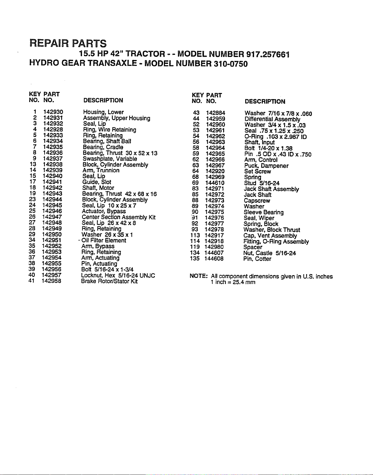
REPAIR PARTS
15.5 HP 42" TRACTOR - - MODEL NUMBER 917.257661
HYDRO GEAR TRANSAXLE - MODEL NUMBER 310-0750
KEY PART KEY PART
NO. NO. DESCRIPTION NO. NO. DESCRIPTION
1 142930 Housing, Lower 43 142684 Washer 7/!6 x 7/8 x .060
2 142931 Assembly, Upper Housing 44 142959 Differential Assembly
3 142932 Seal, Lip 52 142960 Washer 3/4 x 1.5 x .03
4 142928 Ring, Wire Retaining 53 142961 Seal .75 x 1.25 x .250
5 142933 Ring, Retaining 54 142962 O-Ring .103 x 2.987 ID
6 142934 Bearing, Shaft Ball 56 142963 Shaft, input
7 142935 Beadng, Cradle 58 142964 Bolt 1/4-20 x 1.38
8 142936 Bearing, Thrust 30 x 52 x 13 59 142965 Pin .50D x .43 ID x .750
9 142937 Swashplate, Variable 62 142966 Arm, Control
13 142938 Block, Cylinder Assembly 63 142967 Puck, Dampener
14 142939 Arm, Trunnion 64 142920 Set Screw
15 142940 Seal, Up 68 142969 Spring
17 142941 Guide, Slot 69 144610 Stud 5/16-24
18 142942 Shaft, Motor 83 142971 Jack Shaft Assembly
19 142943 Beadng, Thrust 42 x 68 x 16 85 142972 Jack Shaft
23 142944 Block, Cylinder Assembly 88 142973 Capscrew
24 142945 Seal, Lip 10 x 25 x 7 89 142974 Washer
25 142946 ActuatoF, Bypass 90 142975 Sleeve Bearing
26 142947 Center Section Assembly Kit '91 142976 Seal, Wiper
27 142948 Seal, Up 26 x 42 x 8 92 142977 Spdng, Block
28 142949 Ring, Retaining 93 142978 Washer, Block Thrust
29 142950 Washer 26 x 35 x I 113 142917 Cap, Vent Assembly
34 142951 - Oil Rlter Element 114 142918 Fitting, O-Ring Assembly
35 142952 Arm, Bypass 119 142980 Spacer
36 142953 Ring, Retaining 134 144607 Nut, Castle 5/16-24
37 142954 Arm, Actuating 135 144608 Pin, Cotter
38 142955 Pin, Actuating
39 142956 Bolt 5/16-24 x 1-3/4
40 142957 Locknut, Hex 5/16-24 UNJC NOTE: All component dimensions given in U.S. inches
41 142958 Brake Rotor/Stator Kit 1 inch = 25.4 mm
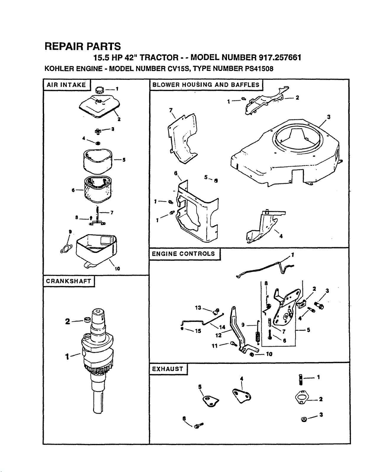
REPAIR PARTS
15.5 HP 42" TRACTOR - - MODEL NUMBER 917.257661
KOHLER ENGINE - MODEL NUMBER CV15S, TYPE NUMBER PS41508
iiillllllli ,,_ ,, _,,, ......,,,,,,,,,,,,,,,,,,
AIR INTAKE! Q__ ,
2
4
+
8 ___ 7
g
I0
iiii ilmml,lllllll i iiiiii
CRANKSHAFT !
IIIl/ll
_" E..........C0NTR0'SI
• +.,._ 15
P iJ
4/
,x.,u++i.......................................
1
5
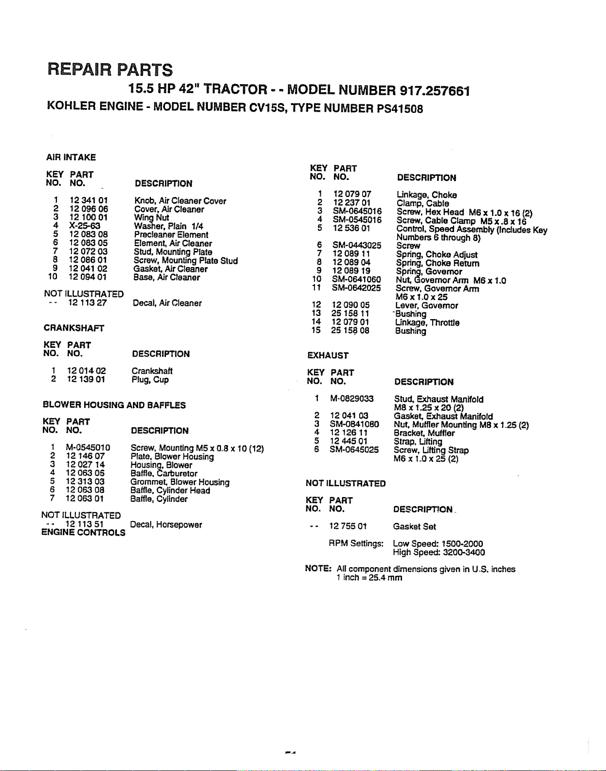
REPAIR PARTS
15.5 HP 42" TRACTOR - - MODEL NUMBER 917.257661
KOHLER ENGINE - MODEL NUMBER CV15S, TYPE NUMBER PS41508
AIR INTAKE
KEY PART
KEY PART NO. NO. DESCRIPTION
NO. NO. DESCRIPTION
1 12 O79 07
1 12 341 01 Knob, Air Cleaner Cover 2 12 237 01
2 t2 096 06 Cover, Air Cleaner 3 SM-0645016
3 12 100 01 WingNut 4 SM.-0545016
4 X-25-63 Was-her, Plain 1/4 5 12 536 01
5 12 083 08 Precleaner Element
6 12 08.3 05 Element, Air Cleaner 6 SM-044.3025
7 12 072 03 Stud. Mounting Plate 7 12 089 11
8 12 086 01 Screw, Mounting Plate Stud 8 12 089 04
9 12 041 02 Gasket, Air Cleaner 9 12 089 19
10 12 094 01 Base, Air Cleaner 10 SM-0641060
11 SM-0642025
NOT ILLUSTRATED
_ t2 113 27 Decal, Air Cleaner
CRANKSHAFT
KEY PART
NO. NO. DESCRIPTION
1 12 014 02 Crankshaft
2 12 139 01 Plug, Cup
BLOWER HOUSING AND BAFFLES
KEY PART
NO. NO. DESCRIPTION
1
2
3
4
5
6
7
M-054,5010
1214607
12 027 14
12 063 05
12 313 03
12 063 08
12 063 01
Screw, Mounting M5 x 0°8 x 10 (12)
Plate, Blower Housing
Housing, Blower
Baffle, Ca.,buretor
Grommet, Blower Housing
Baffle, Cylinder Head
Baffle, Cylinder
NOT ILLUSTRATED
- - 12 113 51 Decal, Horsepower
ENGINE CONTROLS
12 12 090 05
13 25 158 11
14 12 079 01
15 25 15608
Linkage, Choke
Clamp, Cable
Screw, Hex Head M6 x 1.0 x 16 (2)
Screw, Cable Clamp M5 x.8 x 16
Control, Speed Assembly (Includes Key
Numbers 6 through 8)
Screw
Spring, Choke Adjust
Spring, Choke Return
Spring, Govemor
Nut, Governor Arm M6 x 1.0
Screw, Governor Arm
M6 x 1.0 x 25
Lever, Govemor
"Busl'ting
Linkage, Throttle
Bushing
EXHAUST
KEY PART
NO. NO,
1 M.0829033
2 12 041 03
3 SM-0841080
4 12 !26 ti
5 12 445 01
6 SM-0645025
DESCRIP3qON
Stud. Exhaust Manifold
M8 x 1.25 x 20 (2)
Gasket, Exhaust Manifold
Nut, Muffler Mounting M8 x Io25 (2)
Bracket. Muffler
Strop, Lifting _.
Screw, Lifting _ap
M6 x t.0 x 25 (2)
NOT ILLUSTRATED
KEY PART
NOr NO. DESCRIPT!ON ,,
-- 12 755 01 Gasket Set
RPM Settings: Low Speed: t500-2000
High Speed-- 3200-3400
NOTE: All component dimensions given in U.S. inches
1 inch = 25°4.mm
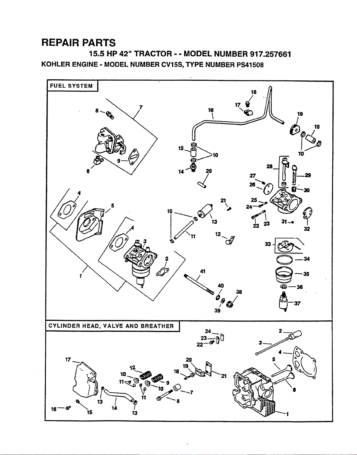
REPAIR PARTS
15.5 HP 42" TRACTOR -- MODEL NUMBER 917.257661
KOHLER ENGINE - MODEL NUMBER CV15S, TYPE NUMBER PS41508
:::::......
FUELSySTEM I
4
7
2
/
LJ jlO
14_" 20
21
IT _ 3
41
39
2_
27
19
10
m
32
_35
_w36
CYLINDER HEAD, VALVE AND BREATHER I
S
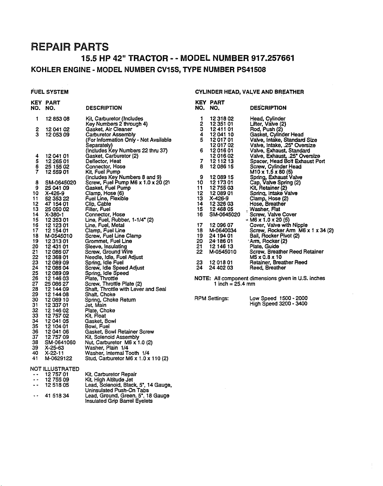
REPAIR PARTS
15.5 HP 42" TRACTOR ..- MODEL NUMBER 917.257661
KOHLER ENGINE - MODEL NUMBER CV15S, TYPE NUMBER PS41508
F_UELSYSTEM
KEY PART
NO. NO.
1 12 853 08
2 12 041 02
3 12 053 09
4 12041 01
5 1226501
6 25 155 02
7 12 559 01
8 SM-0645020
9 25 041 09
10 X-426-9
11 52 353 22
12 47 15401
13 25 050 02
14 X-380-1
15 1235301
16 12 12301
17 12 15401
18 M-0545010
19 1231301
20 12 4-31 01
2! 12 086 07
22 12 368 01
23 12 089 09
24 12 086 04
25 12 089 09
26 12 146 03
27 25 086 27
28 12 144 09
29 12 14408
30 12 089 t0
31 12 337 01
32 12 146 02
33 12 757 02
34 12 041 05
35 12 104 01
36 12 041 06
37 12 757 09
38 SM-0641060
39 X-25-63
40 )(-22-11
41 M-0629122
NOT ILLUSTRATED
-- 12 75701
- - 12 755 09
-- 1251805
-- 41 518 34
CYLINDER HEAD, VALVE AND BREATHER
KEY PART
DESCRIPTION NO. NO. DESCRIPTION
Kit, Carburetor (Includes
Key Numbers 2 through4)
Gasket, Air Cleaner
Carburetor Assembly
(For Information Only - Not Available
Separately)
(Includes Key Numbers 22 thrg 37)
Gasket, Carburetor (2)
Deflector, Heat
Connector, Hose
Kit, Fuel Pump
(Includes Key Numbers 8 and 9)
Screw, Fuel Pump M6 x 1.0 x 20 (2_
Gasket, Fuel Pump
Clamp, Hose (6)
Fuel Line, Rexible
CItp, Cable
Filter, Fuel
Connector, Hose
Line, Fuel, Rubber, 1-I/4" (2)
Line, Fue!, Metal
Clamp, Fuel Line
Screw, Fuel Line Clamp
Grommet, Fuel Line
Sleeve, Insulating
Screw, Ground Wire
Needle, Idle, Fuel Adjust
Spring, idle Fuel
Screw, idle Speed Adjust
Spring, Idle Speed
Plate, Throttle
Screw, Throttle Plate (2)
Shaft, Throttle with Lever and Sea]
Shaft, Choke
Spring, Choke Retum
Jet, Main
Plate, Choke
K_t,Float
Gasket, Bowl
Bowl, Fuel
Gasket. Bowl Retainer Screw
Ki!, Solenoid Assembly
Nut, Carburetor M6 x 1o0(2)
Washer, Plain 1/4
Washer, Intema] Tooth 1/4
Stud. Carburetor M6 x 1_0x 110 (2)
Kit, Carburetor Repair
Kit, High Al_Jde Jet
Lead, Solenoid, Black, 5", 14 Gauge,
Uninsulated Push-On Tabs
Lead, Ground, Green, 5", 18 Gauge
insulated Grip Barrel Eyelets
1
2
3
4
5
7
8
12 318 02
12 351 01
12411 01
12 041 10
12 0t7 01
12 017 02
12 016 01
1201602
12 112 13
12 086 15
9 12089 15
10 12 173 01
11 1275503
12 12 089 01
13 )(-426-9
14 t2 326 03
15 12 468 05
!6 SM-0645020
17 12 096 07
18 M-0640034
19 24 19401
20 2¢ 186 01
21 12 146 13
22 M-0545010
23 12 018 01
24 24 402 03
Head, Cylinder
Lifter, Valve (2)
Rod, Push (2)
Gasket, Cylinder Head
Valve, Intake, Standard Size
Valve, Intake, .25" Oversize
Valve, Exhaust, Standard
Valve, Exhaust, .2.5" Oversize
Spacer. Head Bolt _ust Port
Screw, Cylinder Head
MIO x 1.5 x 80 (5)
Spring, Exhaust Valve
Cap, Valve Spring (2)
Kit, Retainer (2)
Sgdnq, Intake Valve
Clamp, Hose (2)
Hose, Breather
. Washer, Rat
Screw, Valve Cover
,, M6 x 1.0 x 20 (5)
Cover, Valve with Nipple
Screw, Rocker Arm M6 x I x 34 (2)
Ball, Rocker Pivot (2)
"Arm, Rocker (2)
Plate, Guide
Screw, Breather Reed Retainer
M5 x0.8x 10
Retainer, Breather Reed
Reed, Breather
NOTE: All component dimensions given in U,S. inches
1 inch = 25.4 mm
RPM Settings: Low Speed 1500 * 2000
High Speed 3200 - 3400
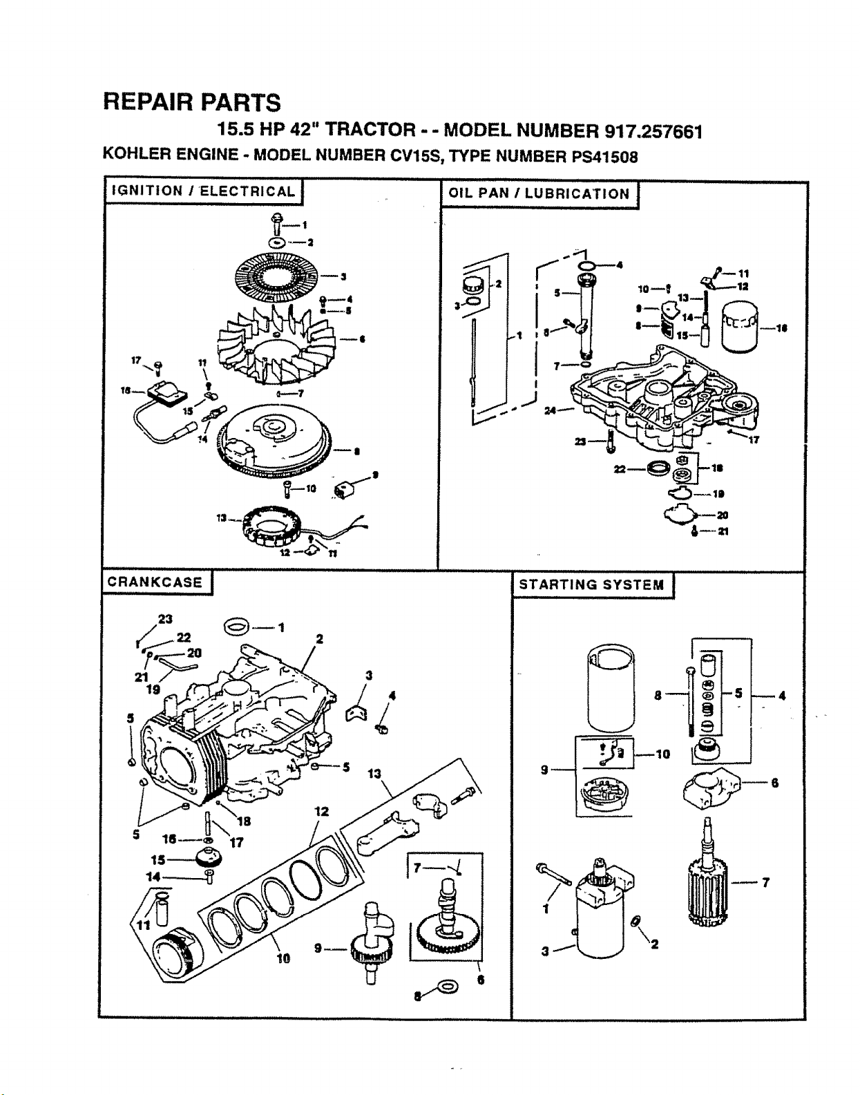
REPAIR PARTS
15.5 HP 42" TRACTOR - - MODEL NUMBER 917,257661
KOHLER ENGINE - MODEL NUMBER CV15S, TYPE NUMBER PS41508
,, ,, , .........................
IGNITION /ELECTRICAL !
_-,
_v..___..
"__'_ __,
CRANKC,,A,SEi
23
21
19
3
13
\
=_::)
STARTING SYSTEM I
--4

REPAUR PARTS
15,5 HP 42" TRACTOR - - MODEL NUMBER 917.257661
KOHLER ENGINE - MODEL NUMBER CV15S, TYPE NUMBER PS41508
IGNITION / ELECTRICAL
CRANKCASE
KEY PART KEY PART
NO. NO. DESCRIP_ON NO. NO. DESCRIPTION
1 12 086 t4 Screw, Flywheel Ml0x 1.5x45.8
2 12 468 03 Washer, Flywheel
3 12 162 03 Screen, Grass
4 M-0639016 Screw, Fan M6 x 1 x 13 (4)
5 12 112 01 Spacer, Fan (4)
6 1215702 Fan
7 X-42_15 Key
8 !2 025 25 Flywheel AssembLy(4 Contact)
9 41 155 02 Connector
!0 M-0548025 Screw, Stator Mounting
M5 x 0_8 x 25 (4)
11 M-0545010 Screw, Stator Harness Clip
M5 x 0.6 x 10 (2)
12 12 154 02 Clip, Stator Harness
13 12 085 03 StatorAssombly
14 12 !32 02 Spark P_ug
15 X-728-1 Clip, Cable
16 12 584 0t Module, Ignition
17 SM-0545020 Screw, ignition Module
M6 x 0.6 x 20 (2)
NOT ILLUSTRATED
- - 12 518 01
Lead, White, Ground To Ki}l(19% 16
Gauge, Fully Insulated Push-on Tab
and Uninsulated Push.on Tab
Terminals)
Kit, Diode
-- 51 75501
OIL PAN t LUBRICATION
DESCRIPTION
KEY PART
NO. NO.
1 1203801
2 25 755 13
3 12 153 03
4 12 153 02
5 12 123 04
6 SM-0545020
7 t2 15301
8 12 162 02
9 12 096 03
10 SM-0545016
tl M-!051025
12 12 12602
13 12 089 03
14 12 462 01
15 t2 208 01
16 12 050 01
17 )(-75-10
18 12 393 01
19 12 032 04
20 12 096 02
21 SM-0545016
Dipstick Assembly
(Includes Key Numbers 2 and 3)
Kit, Oil Fill Cap (Includes Key #3)
O-Ring, Dipstick
O-Ring, Upper Oil Fill Tube
Tube, Oit Fill
Screw, Oil Fill Tube M5 x 03 x 20
O-Ring, Lower Oil F_IITube
Screen, Oil Pick-up
Cover, Oil Pick-up Screen
Screw, Screen Cover
Screw, Oil Pump Relief Valve Bracket
M10 x 1o5x 25
Bracket, Oil Pump Relief Valve
Spring, Oil Pump Relief Valve
Piston, Oil Pump ReLiefValve
Body, Oil Pump Relief Valve
Filter, Oil
Plug, Square Head, Solid 3/8 NPTF
Oil Pump Assembly
O-Ring, Oil Pump Cover
Cover, Oil Pump
Screw, Oil Pump Cover
M5 x 0.8 x 16 (3)
Seal, Oil (P.T.O. End)
Screw, Oil Pan M8 x 12.5 x 45 (12)
Pan, Oil
22 12 032 03
23 SM-0839045
24 12 199 30
i 12 032 0-3
3 12 445 02
4 M-0839025
5 12 380 03
6 12 01002
7 12089 18
8 12 422 08
12 422 09
t2 422 10
12 422 11
12422 t2
12 422 13
12 422 07
9 12 144 19
i0 12 874 07
12 874 08
12 874 09
11 1201802
12 12 108 07
12 108 08
12 108 09
13 1206701
12 067 02
!4 1238001
15 1204306
16 SM-0631005
t7 1214402
18 52 139 09
19 12 14401
20 SM-0631015
21 12 032 01
22 X-25-102
23 12 38004
STARTING SYSTEM
Seal, Crankshaft
Block, C.y!tnder(Use Short Btock)
trap, Lifting
Screw, L_ng Strap M8 x 1.25 x 22
Dowel, Locating (4)
Camshaft Assembly (includes #7)
Spring, Actuating
Shim, Camshaft
Shim, Camshaft (as required)
Shim, Camshaft (as required)
Shim, Camshaft (as required)
Shim, Camshaft (as required)
Shim, Camshaft (as required)
Shim, Camshaft (as requirea)
Shaft. Balance
Piston wiRing Set, Standard
=PistonwiRing Set .25" Oversize
Piston w/Ring Set .50" Oversize
Retainer, Pistori Pin (2)
Ring Set, Standard
Ring Set o25" Oversize
Ring Set .50" Oversize
Connecting Rod, Standard
Connecting Rod-.25" Oversize
Pin, Governor Regulating
Gear, Governor Assembly
Washer, Governor Gear Thrust
Shaft, Governor Gear
Plug, Cup
Shaft, Governor Cross
Washer, Govemor Shaft
Seal, Governor Cross Shaft
Washer, Plain 1/4
Pin, Governor Hitch
KEY PART
NO_ NO. DESCRIPTION
1 M-0839070 Screw, Bendix Starter
M8 x 1/25 x 70 (2)
2 12 468 01 Washer (2)
3 12 098 05 Starter Bendix (Includes #4-10)
4 12 755 12 Kit, Drive (Includes Key Number 5)
5 12 755 06 Kit, Drive Parts
6 12 227 01 Cap, Drive End
7 12 170 02 Armature
8 12 086 02 Screw, Hex Range
9 12 243 01 Cap, Commutator End
(Includes Key Number 10)
10 82 755 28 Kit, Brush and Spring
NOT ILLUSTRATED
- - 52 357 01 LubdcanL Starter
NOTE: All component dimensions given in U.S. inches
1 inch = 25.4 mm

SERVICE NOTES


iiiiiiiiJll ii iiii i iiij i iii iljl i i iiii1=,,i ,,,,,,,,,, , ,, _ iii ii iiiiiii i,
S
...................... i Jl .......................... i IUL II I UII'I Jill iiiii /
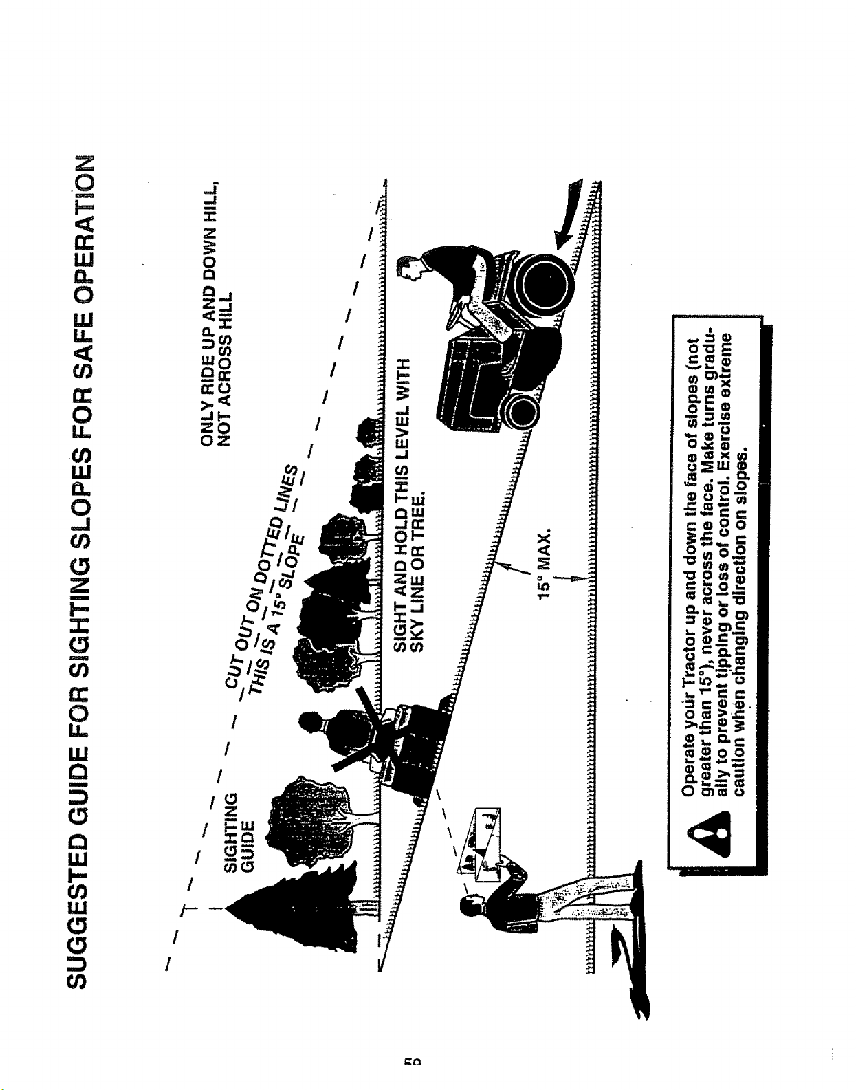
Z
_0
m
UJ
0
W
t_
0
I.L
0
,.,,J
Z
t
!.=,
l
ri-
O
u.
LU
M
t_
LU
i'-
UJ
(,.9
/
/
/--.
/
/
0
/
/
/
/
/
/
/
/
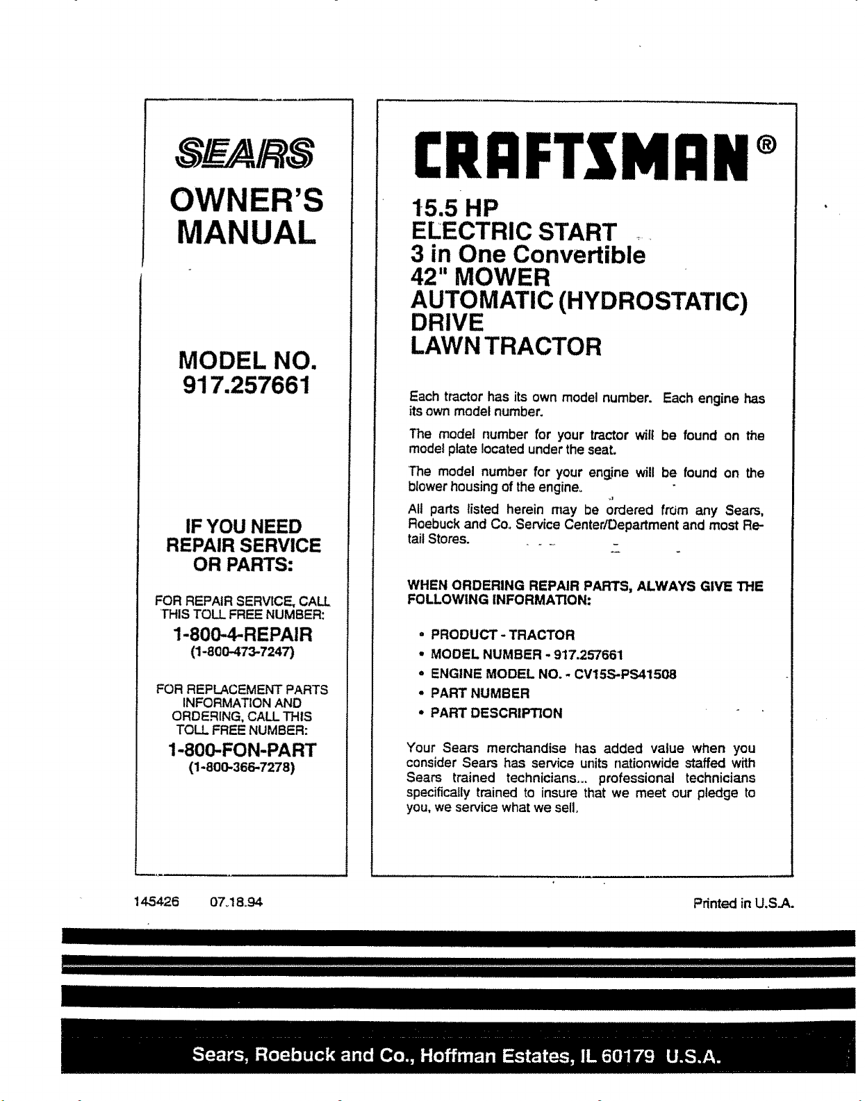
OWNER'S
MODEL NO.
917.257661
IF YOU NEED
REPAIR SERVICE
OR PARTS:
FOR REPAIR SERVICE, CALL
'THISTO_ FREE NUMBER:
1-800-4-REPAIR
(1-800473-7247)
FOR REPLACEMENT'PARTS
INFORMATION AND
ORDERING, CALLTHIS
TOLL FREE NUMBER:
1-800-.FON-PART
(1-800-366-7278)
CRIIFTSMIIN®
15.5 HP
ELECTRIC START .....
3 in One Convertible
42" MOWER
AUTOMATIC (HYDROSTATIC)
DRIVE
LAWN TRACTOR
Each tractor has its own model number. Each engine has
its own model number.
The model number for your tractor wilt be found on the
model plate located under the seat.
'The model number for your engine will be found on the
blower housing of the engine°
All parts listed herein may be ordered frOm any Seam,
Roebuck and Co. Service CentedDepartment and most Re-
tail Stores.
WHEN ORDERING REPAIR PARTS, ALWAYS GIVE THE
FOLLOWING INFORMATION:
• PRODUCT- TRACTOR
,, MODEL NUMBER - 917.257661
• ENGINE MODEL NO. - CV15S-PS41508
• PART NUMBER
° PART DESCRIPTION
Your Sears merchandise has added value when you
consider Sears has service units nationwide staffed with
Sears trained technicians.,, professional technicians
specifically trained to insure that we meet our pledge to
you, we service what we sell,
145426 07o18_94 Printed in U.S.A.