Loading ...
Loading ...
Loading ...
Checktheadjustmentbyplacingtheliftleverinthe
BLADESSTOPposition.Thedeckshouldmoveupand
forward,allowingthebelttobecomeloose.Startand
testfordisengagement.Repeatprocedureas
necessary.
Stabilizer Shaft
Assembly
Disengagement
Slot
Shift
Lever
Hairpin Clip [38" Decks I
Stabilizer Shaft Disengagement
Assembly Rod
Spiing
Hairpin Clip I 42" and ]
46" Decks J
Figure 14
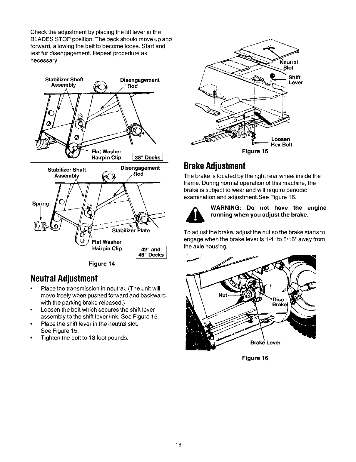
NeutralAdjustment
• Place the transmission in neutral. (The unit will
move freely when pushed forward and backward
with the parking brake released.)
• Loosen the bolt which secures the shift lever
assembly to the shift lever link. See Figure 15.
• Place the shift lever in the neutral slot.
See Figure 15.
• Tighten the bolt to 13 foot pounds.
Loosen
Hex Bolt
Figure 15
BrakeAdjustment
The brake is located by the right rear wheel inside the
frame. During normal operation of this machine, the
brake is subject to wear and will require periodic
examination and adjustment.See Figure 16.
,_ WARNING: Do not have the engine
running when you adjust the brake.
To adjust the brake, adjust the nut so the brake starts to
engage when the brake lever is 1/4" to 5/16" away from
the axle housing.
Figure 16
16
Loading ...
Loading ...
Loading ...