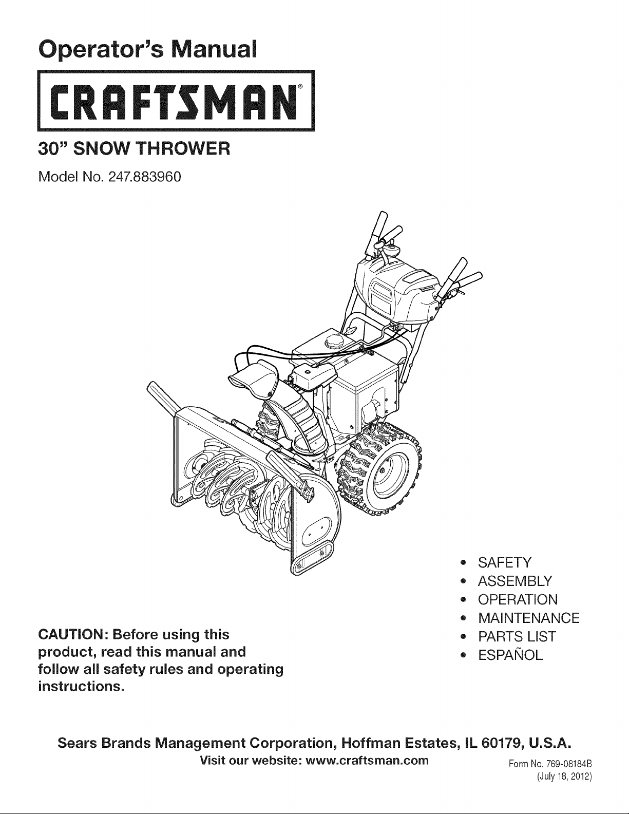
Operator's Manual
CRRFr MRN
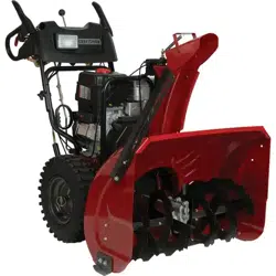
30" SNOW THROWER
Model No. 247.883960
CAUTION" Before using this
product, read this manual and
follow all safety rules and operating
instructions.
,, SAFETY
o ASSEMBLY
OPERATION
MAINTENANCE
PARTS LIST
o ESPANOL
Sears Brands Management Corporation, Hoffman Estates, IL 60179, U.S.A.
Visit our website: www.craftsman.com FormNo.769-08184B
(July 18,2012)
WarrantyStatement.................... Page2
SafeOperationPractices.............. Pages3-6
Assembly......................... Pages8-12
Operation........................ Pages13-17
Service&Maintenance.............. Pages18-23
Off-SeasonStorage................... Page24
Troubleshooting...................... Page25
PartsList......................... Pages26-41
RepairProtectionAgreement............ Page45
Espadol............................. Page46
ServiceNumbers................... BackPage
CRAFTSMANTWOYEARFULLWARRANTY
FORTWOYEARSfromthedateofpurchase,thisproductiswarrantedagainstanydefectsinmaterialorworkmanship.Defectiveproductwill
receivefreerepairorfreereplacementifrepairisunavailable.
ADDiTiONAL LiFETiME LiMiTED WARRANTY on UPPER and LOWER CHUTE
FORAS LONGAS ITIS USEDbythe originalownerafterthe secondyear fromthe dateof purchase,theupperandlowerchuteof this snow
throwerarewarrantedagainstany defectsinmaterialorworkmanshipas verifiedby a Searsauthorizedserviceprovider.With proofof purchase,
youwill receivea newchutefree of charge.Youare responsiblefor the laborcost of installationand any costincurredto verify thedefect.
Forwarrantycoveragedetailsto obtainrepairor replacement,visitthe web site:www.craftsman.com
ThiswarrantycoversONLYdefectsin materialandworkmanship.Warrantycoveragedoes NOTinclude:
• Expendableitemsthat can wearoutfrom normalusewithin thewarrantyperiod,includingbut not limitedto augers,auger paddles,drift
cutters,skidshoes,shaveplate,shearpins,sparkplug,air cleaner,belts,and oil filter.
• Standardmaintenanceservicing,oil changes,or tune-ups.
Tire replacementor repaircausedby puncturesfromoutsideobjects,suchas nails,thorns,stumps,or glass.
• Tireor wheelreplacementor repairresultingfrom normalwear,accident,or improperoperationor maintenance.
Repairsnecessarybecauseof operatorabuse,includingbutnot limitedto damagecausedby over-speedingthe engine,or from impacting
objectsthat bendthe frame,auger shaft,etc.
• Repairsnecessarybecauseof operatornegligence,includingbut not limitedto, electricaland mechanicaldamagecausedby improper
storage,failureto usethe propergradeandamountof engineoil, or failureto maintainthe equipmentaccordingto the instructionscontained
inthe operator'smanual.
• Engine(fuelsystem)cleaningor repairscausedbyfuel determinedto becontaminatedor oxidized(stale).in general,fuel shouldbe used
within30 daysof its purchasedate.
Normaldeteriorationandwearof the exteriorfinishes,or productlabelreplacement.
Thiswarrantyis void if thisproductis ever usedwhileprovidingcommercialservicesor if rentedto anotherperson.
Thiswarrantygivesyou specificlegalrights,and you mayalso haveotherrightswhichvary from stateto state.
Sears Brands Management Corporation, Hoffman Estates, IL 60179
EngineOilType: SAE5W-30
EngineOilCapacity: 37ounces
FuelCapacity: Approx.5Quarts
SparkPlug: F6RTC(951-10292)
SparkPlugGap: .020"to .030"
Model Number.................................................................
Serial Number .................................................................
Dateof Purchase.............................................................
Recordthe modelnumber,serialnumber
anddateof purchaseabove
© Sears Brands,LLC
2
Thissymbolpointsout importantsafetyinstructionswhich,if not
followed,couldendangerthepersonalsafetyand/orpropertyof
yourselfandothers. Readand followall instructionsin thismanual
beforeattemptingto operatethismachine.Failureto complywith
theseinstructionsmayresultin personalinjury.Whenyou seethis
symbol,HEEDITSWARNING!
CALIFORNIA PROPOSITION 65
EngineExhaust,someof its constituents,andcertainvehicle
componentscontainoremit chemicalsknownto Stateof California
to causecancerandbirthdefects or otherreproductiveharm,
Thismachinewasbuiltto beoperatedaccordingto the safeopera-
tion practicesinthis manual.As withanytypeof powerequipment,
carelessnessor error on the partof the operatorcan resultin serious
injury.Thismachineis capableof amputatingfingers,hands,toes
andfeet and throwingdebris.Failureto observethe followingsafety
instructionscouldresultin seriousinjuryor death.
Your Responsibility--Restrict the use of thispowermachineto
personswho read,understandandfollow thewarningsand instruc-
tionsin this manualand on the machine,
SAVE THESE INSTRUCTIONS!
TRAiNiNG
• Read,understand,and followall instructionson the machineand
in themanual(s)beforeattemptingto assembleand operate.
Failureto do socan resultinserious injuryto the operatorand/
orbystanders.Keepthismanualin a safe placeforfuture and
regularreferenceandfor orderingreplacementparts.
• Befamiliarwithall controlsandtheir properoperation.Knowhow
to stopthe machineanddisengagethemquickly.
• Neverallowchildrenunder14 yearsof age to operatethis
machine.Children14andover shouldreadand understandthe
instructionsand safe operationpracticesin this manualand on
the machineandbe trainedand supervisedby an adult.
Neverallowadultsto operatethis machinewithoutproper
instruction.
• Thrownobjectscan causeseriouspersonalinjury.Planyour
snow-throwingpatternto avoiddischargeof materialtoward
roads,bystandersand the like.
Keepbystanders,pets and childrenat least75feetfromthe
machinewhile it is in operation.Stopmachineif anyoneenters
the area.
• Exercisecautionto avoidslippingor falling,especiallywhen
operatingin reverse.
PREPARATION
Thoroughlyinspectthearea wherethe equipmentisto be used.
Removeall doormats,newspapers,sleds,boards,wires and other
foreignobjects,whichcouldbe trippedoveror thrownby the auger/
impeller.
• Alwayswear safetyglassesor eyeshieldsduringoperationand
while performingan adjustmentor repairto protectyoureyes.
Thrownobjectswhichricochetcancause seriousinjuryto the
eyes.
Donot operatewithoutwearingadequatewinteroutergarments.
Donot wearjewelry,longscarvesorotherlooseclothing,which
could becomeentangledin movingparts.Wearfootwearwhich
will improvefootingonslipperysurfaces.
Usea groundedthree-wireextensioncordand receptaclefor all
machineswith electricstartengines.
Disengageall controlleversbeforestartingthe engine.
Adjustcollectorhousingheightto cleargravelor crushedrock
surfaces.
• Neverattemptto make anyadjustmentswhileengineis running,
exceptwherespecificallyrecommendedinthe operator'smanual.
Letengineandmachineadjustto outdoortemperaturebefore
startingto clearsnow.
3
Safe Handling of Gasoline
Toavoidpersonalinjuryor propertydamageuseextremecare in
handlinggasoline.Gasolineis extremelyflammableand the vaporsare
explosive.Seriouspersonalinjurycan occurwhengasolineis spilled
onyourselfor yourclotheswhichcan ignite. Washyour skin and
changeclothesimmediately.
• Useonlyan approvedgasolinecontainer.
• Extinguishallcigarettes,cigars,pipesand other sourcesof
ignition.
• Neverfuel machineindoors.
• Neverremovegas capor addfuel whilethe engineis hot or
running.
• Allowengineto coolat leasttwo minutesbeforerefueling.
• Neveroverfill fueltank. Fill tankto nomorethan1/2inchbelow
bottomof filler neckto providespaceforfuel expansion.
• Replacegasolinecapandtighten securely.
• Ifgasolineis spilled,wipe it off theengineandequipment.Move
machineto anotherarea.Wait5 minutesbeforestartingthe
engine.
• Neverstorethe machineorfuel containerinsidewherethereis an
openflame,sparkor pilotlight(e.g. furnace,waterheater,space
heater,clothesdryeretc.).
• Allowmachineto cool at least5 minutesbeforestoring.
• Neverfill containersinsidea vehicleor ona truckor trailerbed
witha plasticliner.Alwaysplacecontainersonthe groundaway
fromyour vehiclebeforefilling.
• If possible,removegas-poweredequipmentfromthe truckor
trailerandrefuelit onthe ground.Ifthis is not possible,then refuel
suchequipmenton a trailerwith a portablecontainer,ratherthan
froma gasolinedispensernozzle.
• Keepthe nozzlein contactwith the rimof the fuel tankor
containeropeningat alltimes untilfuelingis complete.Do not use
a nozzlelock-opendevice.
OPERATION
• Do not puthandsorfeetnear rotatingparts,in the auger/impeller
housingor chuteassembly.Contactwith the rotatingpartscan
amputatehandsandfeet.
• Theauger/impellercontrolleveris a safetydevice.Neverbypass
itsoperation.Doingso makesthe machineunsafeandmay cause
personalinjury.
• Thecontrolleversmustoperateeasilyin bothdirectionsand
automaticallyreturnto the disengagedpositionwhenreleased.
• Neveroperatewitha missingor damagedchuteassembly.Keep
all safetydevicesin placeand working.
• Neverrunan engine indoorsor in a poorlyventilatedarea. Engine
exhaustcontainscarbonmonoxide,an odorlessand deadlygas.
• Do notoperatemachinewhileunderthe influenceof alcoholor
drugs.
• Mufflerandengine becomehotand can causea burn.Do not
touch.Keepchildrenaway.
• Exerciseextremecautionwhenoperatingon or crossinggravel
surfaces.Stayalertfor hiddenhazardsor traffic.
Exercisecautionwhenchangingdirectionand whileoperatingon
slopes.Do notoperateon steep slopes.
Planyoursnow-throwingpatternto avoiddischargetowards
windows,walls,carsetc. Thus,avoidingpossibleproperty
damageor personalinjurycausedby a ricochet.
Neverdirectdischargeat children,bystandersand petsor allow
anyoneinfront of the machine.
Donot overloadmachinecapacityby attemptingto clearsnowat
too fastof a rate.
Neveroperatethis machinewithoutgoodvisibilityor light. Always
be sureof yourfootingand keepa firm hold on the handles.Walk,
neverrun.
Disengagepowerto theauger/impellerwhentransportingor not
in use.
Neveroperatemachineat hightransportspeedson slippery
surfaces.Lookdownand behindand usecare whenbackingup.
Ifthe machineshouldstart to vibrateabnormally,stop the engine,
disconnectthe sparkplugwire and groundit againstthe engine.
Inspectthoroughlyfor damage.Repairanydamagebefore
startingandoperating.
Disengageall controlleversandstop enginebeforeyouleave
the operatingposition(behindthe handles).Wait untilthe auger/
impellercomesto a completestopbeforeuncloggingthechute
assembly,makingany adjustments,or inspections.
Neverput yourhandin the dischargeor collectoropenings.Do
not unclogchuteassemblywhileengineis running.Shutoff
engineand remainbehindhandlesuntilall movingparts have
stoppedbeforeunclogging.
Useonly attachmentsandaccessoriesapprovedby the manufac-
turer (e.g.wheelweights,tire chains,cabsetc.). Forinformation
concerningtheseitems,call 1-800-469-4663.
Whenstartingengine,pullcord slowlyuntilresistanceis felt, then
pull rapidly.Rapidretractionof startercord(kickback)will pull
handand armtowardenginefasterthan youcan let go. Broken
bones,fractures,bruisesor sprainscould result.
Ifsituationsoccurwhichare notcoveredin this manual,use care
andgood judgment.
Toorderpartsor scheduleservicefor this product,call 1-800-
469-4663.
CLEARING A CLOGGED DISCHARGE CHUTE
Handcontactwiththe rotatingimpellerinsidethe dischargechute
is the mostcommoncauseof injuryassociatedwithsnowthrowers.
Neveruse yourhandto cleanout thedischargechute.
Toclear thechute:
1. SHUTTHEENGINEOFF!
2. Wait 10secondsto be surethe impellerbladeshavestopped
rotating.
3. Alwaysusea clean-outtool,not yourhands.
4
MAINTENANCE & STORAGE
• Nevertamperwithsafetydevices.Checktheirproperoperation
regularly.Referto the maintenanceand adjustmentsectionsof
thismanual.
• Beforecleaning,repairing,or inspectingmachinedisengageall
controlleversandstop the engine.Wait untilthe auger/impeller
cometo a completestop.Disconnectthe sparkplug wireand
groundagainsttheengineto preventunintendedstarting.
Checkboltsand screwsfor propertightnessat frequentintervals
to keepthe machineinsafeworkingcondition.Also, visually
inspectmachinefor anydamage.
Do notchangetheenginegovernorsettingor over-speedthe
engine.Thegovernorcontrolsthe maximumsafeoperatingspeed
of the engine.
Snowthrowershaveplatesand skid shoesare subjectto wear
anddamage.Foryoursafetyprotection,frequentlycheckall
componentsand replacewith originalequipmentmanufacturer's
(OEM)partsonlyas listedinthe Partspagesof thisoperator's
manual.Useof partswhich do not meetthe originalequipment
specificationsmayleadto improperperformanceand compro-
misesafety!
Checkcontrolleversperiodicallyto verifytheyengageand disen-
gageproperlyand adjust,if necessary.Referto the adjustment
sectioninthisoperator'smanualfor instructions.
Maintainor replacesafetyandinstructionlabels,as necessary.
Observeproperdisposallawsand regulationsfor gas, oil,etc. to
protectthe environment.
Priorto storing,runmachinea few minutestoclear snowfrom
machineand preventfreezeup of auger/impeller.
Neverstorethe machineorfuel containerinsidewherethereisan
openflame,spark or pilot lightsuch as a waterheater,furnace,
clothesdryer etc.
Alwaysreferto the operator'smanualfor properinstructionson
off-seasonstorage.
Checkfuelline,tank, cap,andfittings frequentlyfor cracksor
leaks.Replaceif necessary.
Do notcrankenginewithspark plug removed.
Accordingto the ConsumerProductsSafetyCommission(CPSC)
andthe U.S.EnvironmentalProtectionAgency(EPA),this product
hasan AverageUsefulLifeof seven(7)years,or 60 hoursof
operation.At the endof theAverageUsefulLifehavethe machine
inspectedannuallybyan authorizedservicedealer to ensurethat
allmechanicalandsafetysystemsare workingproperlyand not
wornexcessively.Failureto do so can resultin accidents,injuries
ordeath.
DO NOT MODIFY ENGINE
Toavoidseriousinjuryor death,do not modifyengine in any way.
Tamperingwiththe governorsettingcanleadto a runawayengineand
causeit to operateat unsafespeeds.Nevertamperwithfactorysetting
of enginegovernor.
NOTICE REGARDING EMiSSiONS
Engineswhich are certifiedtocomplywith Californiaand federal
EPAemissionregulationsfor SORE(SmallOff RoadEquipment)are
certifiedto operateon regularunleadedgasoline,and mayinclude
the followingemissioncontrolsystems:EngineModification(EM),
OxidizingCatalyst(OC),SecondaryAirInjection(SAI)and ThreeWay
Catalyst(TWO)if so equipped.
SPARK ARRESTOR
Thismachineisequippedwithan internalcombustionengineand
shouldnotbe usedon or nearany unimprovedforest-covered,
brush-coveredor grass-coveredland unlessthe engine'sexhaust
systemisequippedwitha sparkarrestormeetingapplicablelocalor
statelaws(if any)
Ifa sparkarrestoris used,it shouldbe maintainedin effectiveworking
orderby theoperator.Inthe Stateof Californiathe aboveis required
bylaw (Section4442of the CaliforniaPublicResourcesCode).Other
statesmayhavesimilarlaws. Federallawsapplyonfederallands.
A sparkarrestorfor the muffleris availablethroughyournearestSears
PartsandRepairServiceCenter.
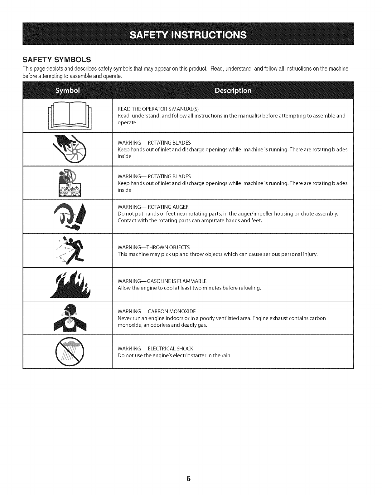
SAFETY SYMBOLS
Thispagedepictsanddescribessafetysymbolsthat mayappear on this product. Read,understand,andfollowall instructionson the machine
beforeattemptingto assembleandoperate.
. +
i
i
"JIp
READ THE OPERATOR'S MANUAL(S)
Read, understand, and follow all instructions in the manual(s) before attempting to assemble and
operate
WARNING-- ROTATING BLADES
Keep hands out of inlet and discharge openings while machine is running. There are rotating blades
inside
WARNING-- ROTATING BLADES
Keep hands out of inlet and discharge openings while machine is running. There are rotating blades
inside
WARNING-- ROTATING AUGER
Do not put hands or feet near rotating parts, in the auger/impeller housing or chute assembly.
Contact with the rotating parts can amputate hands and feet.
WARNING--THROWN OBJECTS
This machine may pick up and throw objects which can cause serious personal injury.
WARNING--GASOLINE IS FLAMMABLE
Allow the engine to cool at least two minutes before refueling.
WARNING-- CARBON MONOXIDE
Never run an engine indoors or in a poorly ventilated area. Engine exhaust contains carbon
monoxide, an odorless and deadly gas+
WARNING-- ELECTRICAL SHOCK
Do not use the engine's electric starter in the rain
6

Thispageleftintentionallyblank.
7
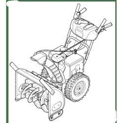
NOTE:Referencesto rightorleft sideof the snowthrowerare
determinedfrombehindthe unit inthe operatingposition(standing
directlybehindthe snowthrower,facingthe handlepanel).
REMOVING FROM CARTON
1. Cutthe cornersof thecartonandlay the sidesflaton the ground.
Removeand discard all packinginserts.
2. Movethe snowthrowerout of thecarton.
3. Makecertainthe cartonhas beencompletelyemptiedbefore
discardingit.
ASSEMBLY
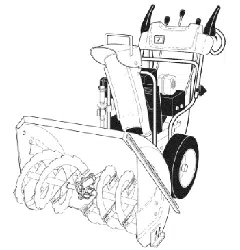
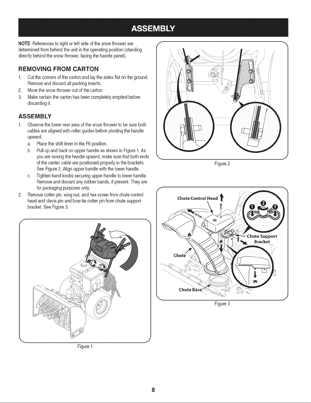
1. Observethe lowerrearareaof the snowthrowerto besure both
cablesarealignedwith rollerguidesbeforepivotingthe handle
upward.
a. Placethe shiftleverin the F6position.
b. Pullupandbackon upperhandleas shownin Figure1.As
youare raisingthe handleupward,make surethat bothends
of the centercablearepositionedproperlyin the brackets.
SeeFigure2. Alignupperhandlewith the lowerhandle.
c. Tightenhandknobssecuringupper handleto lowerhandle.
Removeand discard any rubberbands,if present.Theyare
for packagingpurposesonly.
2. Removecotter pin,wingnut,and hexscrewfromchutecontrol
headandclevis pin and bow-tiecotterpin from chutesupport
bracket.See Figure3.
Figure2
Chute Control Head
Figure3
Figure1
8
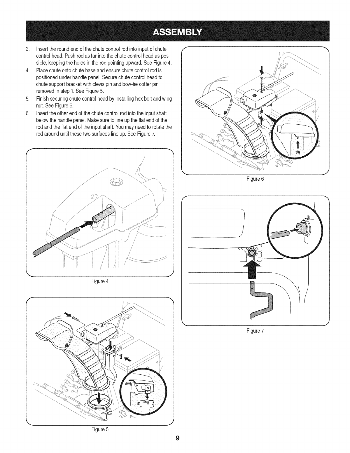
3. insertthe roundendof the chutecontrolrodinto inputof chute
controlhead.Pushrodas far intothe chutecontrol headas pos-
sible,keepingthe holesin the rod pointingupward.See Figure4.
4. Placechuteontochutebaseandensurechutecontrolrodis
positionedunderhandlepanel.Securechutecontrol headto
chutesupportbracketwith clevispin and bow-tiecotterpin
removedin step1.See Figure5.
5. Finishsecuringchutecontrolheadby installinghex boltandwing
nut.See Figure6.
6. insertthe otherendof the chutecontrolrodintothe inputshaft
belowthe handlepanel.Makesureto lineup the flat end of the
rodandthe fiat end of the input shaft.Youmay need to rotatethe
rodarounduntilthesetwo surfacesline up. See Figure7.
f
/
/
,/
/
i'_...........................
i
Figure4
,J
J
Figure6
Figure7
Figure5
J
9
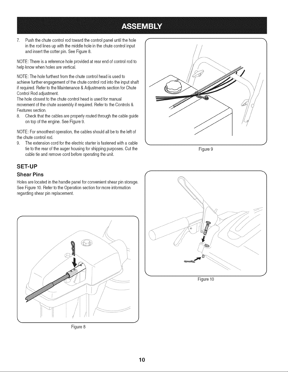
7. Pushthe chutecontrolrodtowardthecontrolpaneluntil the hole
inthe rodlines upwiththe middleholeinthe chutecontrolinput
and insertthe cotterpin. SeeFigure8.
NOTE:Thereis a referenceholeprovidedat rearend of controlrodto
helpknowwhenholesare vertical.
NOTE:The holefurthestfromthe chutecontrol headis usedto
achievefurtherengagementof thechute controlrod intothe inputshaft
if required.Referto the Maintenance& Adjustmentssectionfor Chute
ControlRodadjustment.
The holeclosestto the chutecontrolheadis usedfor manual
movementof the chuteassemblyif required.Referto the Controls&
Featuressection.
8. Checkthat the cablesare properlyroutedthroughthecableguide
on topof the engine.SeeFigure9.
NOTE:For smoothestoperation,the cablesshouldall be to the left of
the chutecontrolrod.
9. The extensioncordfor the electricstarteris fastenedwitha cable
tie to the rearof the augerhousingfor shippingpurposes.Cut the
cable tie andremovecord beforeoperatingthe unit.
Figure9
SET-UP
Shear Pins
Holesarelocatedin the handlepanelfor convenientshearpinstorage.
SeeFigure10.Refertothe Operationsectionfor moreinformation
regardingshearpinreplacement.
Figure8
J
f
Figure10
10
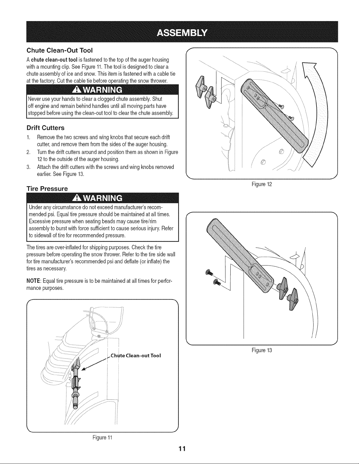
Chute Clean-Out Tool
A chute clean-outtool is fastenedto the top of theaugerhousing
witha mountingclip.See Figure11.Thetool is designedto cleara
chuteassemblyof iceand snow.This item is fastenedwitha cabletie
at the factory.Cutthe cabletie beforeoperatingthe snowthrower.
Neveruseyourhandsto cleara cloggedchuteassembly.Shut
loft engineand remainbehindhandlesuntilall movingparts have
I stoppedbeforeusingtheclean-outtool to clearthe chuteassembly.
Drift Cutters
1. Removethetwo screwsandwing knobsthatsecureeachdrift
cutter,andremovethem from the sidesof the auger housing.
2. Turnthe driftcuttersaroundandpositionthemas shownin Figure
12to theoutsideof the augerhousing.
3. Attachthedrift cutterswiththe screwsand wingknobsremoved
earlier.SeeFigure13.
Tire Pressure
Underanycircumstancedo notexceedmanufacturer'srecom-
mendedpsi. Equaltire pressureshouldbe maintainedat all times.
Excessivepressurewhenseatingbeadsmaycausetire/rim
assemblyto burstwithforce sufficientto causeseriousinjury. Refer
to sidewallof tirefor recommendedpressure.
Thetiresareover-inflatedfor shippingpurposes.Checkthe tire
pressurebeforeoperatingthe snow thrower.Referto the tire sidewall
for tire manufacturer'srecommendedpsi anddeflate(or inflate)the
tiresas necessary.
f
/
/
Figure12
J
NOTE:Equaltire pressureis to bemaintainedatall timesfor perfor-
mancepurposes.
Figure13
Figure11
11
ADJUSTMENTS
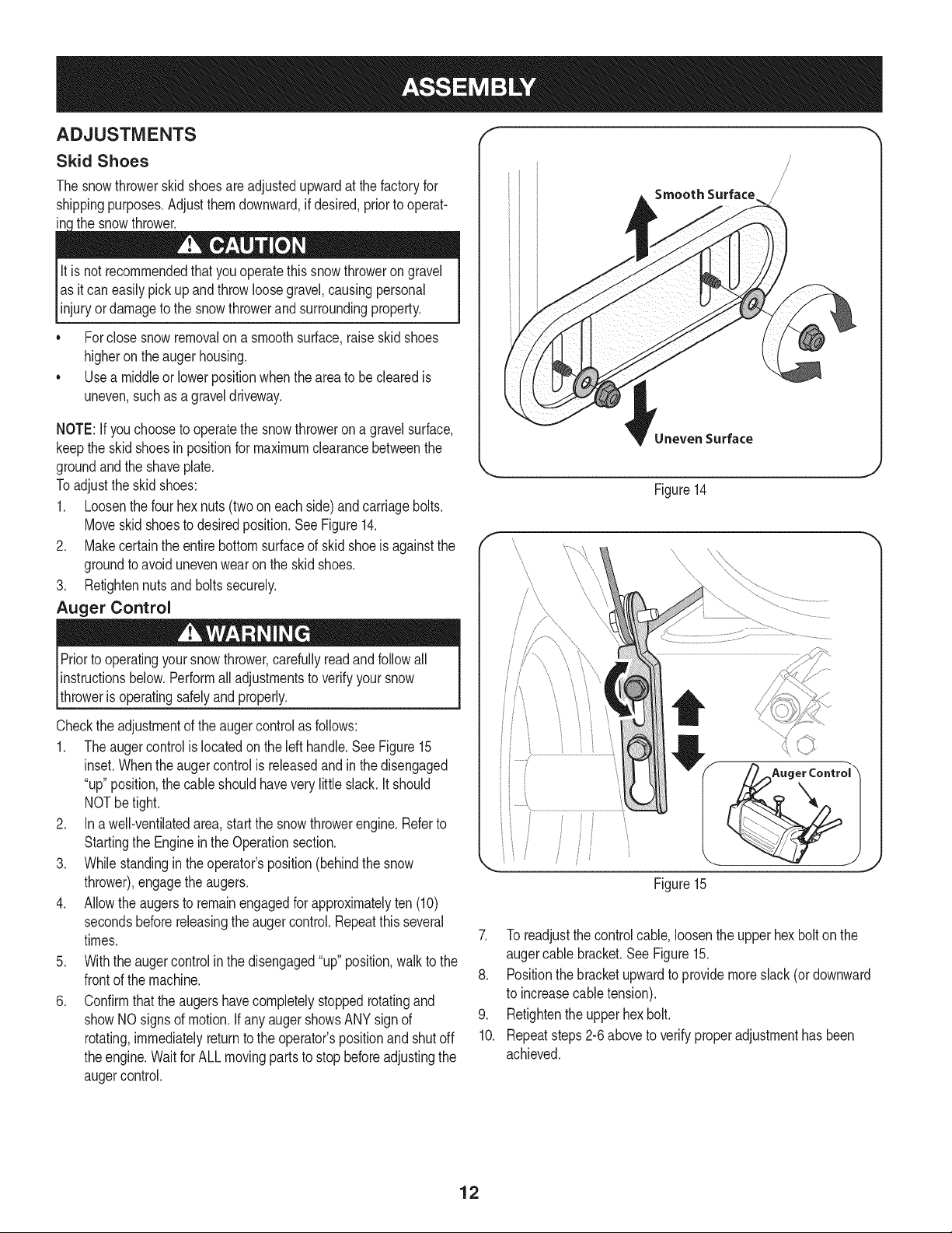
Skid Shoes
The snowthrowerskidshoesare adjustedupwardat thefactory for
shippingpurposes.Adjustthemdownward,if desired,priorto operat-
in the snowthrower.
lit is not recommendedthat this thrower
you operate
snow on
gravel
as itcan easilypickupand throw loosegravel,causingpersonal
injuryordamageto the snowthrowerandsurroundingproperty.
• Forclosesnowremovalona smoothsurface,raiseskid shoes
higheronthe auger housing.
• Usea middleor lowerpositionwhentheareato be clearedis
uneven,suchas a graveldriveway.
NOTE:If youchooseto operatethe snowthrowerona gravelsurface,
keepthe skidshoesin positionfor maximumclearancebetweenthe
groundandthe shaveplate.
Toadjustthe skidshoes:
1. Loosenthe four hexnuts(twooneach side)andcarriagebolts.
Moveskidshoesto desiredposition.See Figure14.
2. Makecertainthe entirebottomsurfaceof skidshoeis againstthe
groundto avoidunevenwearonthe skid shoes.
3. Retightennutsand boltssecurely.
Auger Control
Priorto operatingyoursnowthrower,carefullyreadandfollowall
instructionsbelow.Performall adjustmentsto verifyyoursnow
throweris operatingsafelyandproperly.
Checkthe adjustmentof the augercontrolas follows:
1. Theaugercontrolis locatedonthe left handle.SeeFigure15
inset.Whentheaugercontrolis releasedandin the disengaged
"up"position,the cableshouldhavevery littleslack.Itshould
NOTbe tight.
2. In a well-ventilatedarea,start the snowthrowerengine.Referto
Startingthe Engineinthe Operationsection.
3. Whilestandinginthe operator'sposition(behindthesnow
thrower),engagethe augers.
4. Allowthe augersto remainengagedfor approximatelyten (10)
secondsbeforereleasingthe auger control.Repeatthis several
times.
5. Withthe augercontrolinthe disengaged"up" position,walkto the
frontof the machine.
6. Confirmthatthe augershavecompletelystoppedrotatingand
showNOsignsof motion.If anyaugershowsANYsign of
rotating,immediatelyreturnto the operator'spositionand shutoff
theengine.Waitfor ALLmovingparts to stop beforeadjustingthe
augercontrol.
Smooth Surface
Uneven Surface
Figure14
Figure15
7. To readjustthe controlcable,loosenthe upperhexbolton the
augercable bracket.See Figure15.
8. Positionthe bracketupwardto providemoreslack(or downward
to increasecabletension).
9. Retightenthe upperhex bolt.
10. Repeatsteps2-6aboveto verifyproperadjustmenthas been
achieved.
12
f Shift Lever
Drive Control Electric Chute Control (Joystick)
Headlight
\\
Manual \
Gas Cap \ ChuteControl\
ChuteAssembly \. \
Drift Cutter
Auger
Housing
Clean Out
Tool
\
Skid Shoe
Auger Control
Wheel Steering Control
Recoil Starter
Oil Fill
Handle
Oil Drain
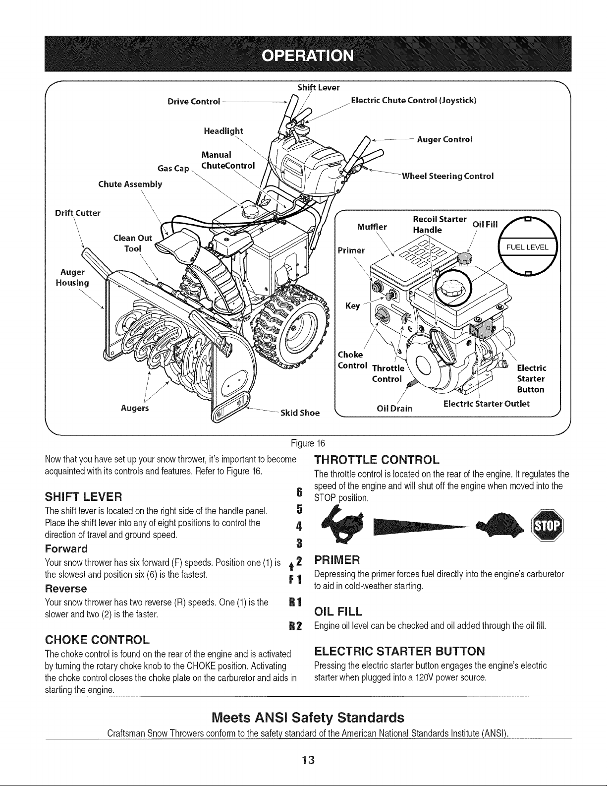
Nowthatyou haveset up your snowthrower,it'simportantto become
acquaintedwith itscontrolsand features.Referto Figure16.
SHIFT LEVER 6
Theshift leveris locatedonthe rightsideof the handlepanel. 5
Placethe shiftleverintoany of eight positionsto control the 4
directionof travelandgroundspeed,
Forward 3
Yoursnowthrowerhas sixforward(F) speeds.Positionone(1)is t 2
the slowestand positionsix (6) is thefastest. F 1
Reverse
Yoursnowthrowerhastwo reverse(R) speeds,One (1) is the
slowerandtwo (2) is the faster.
J
Figure16
THROTTLE CONTROL
The throttlecontrolis locatedonthe rear of the engine.Itregulatesthe
speedof the engineandwill shutoff the enginewhen movedinto the
STOPposition.
R1
R2
CHOKE CONTROL
Thechokecontrolis foundon the rear of the engineand is activated
by turningthe rotarychokeknobto the CHOKEposition.Activating
the chokecontrolclosesthe chokeplateonthe carburetorand aids in
startingthe engine.
PRIMER
Depressingthe primerforcesfueldirectlyintothe engine'scarburetor
to aid incold-weatherstarting.
OIL FILL
Engineoil levelcan becheckedand oil addedthroughthe oil fill.
ELECTRIC STARTER BUTTON
Pressingtheelectricstarterbuttonengagesthe engine'selectric
starterwhenpluggedintoa 120Vpowersource.
Meets ANSi Safety Standards
CraftsmanSnowThrowersconformtothe safetystandardof the AmericanNationalStandardsInstitute(ANSI).
13
ELECTRIC STARTER OUTLET
Requiresthe useof a three-prongoutdoorextensioncord(included)
anda 120Vpowersource/walloutlet.
KEY
The keyisa safetydevice.It mustbefully insertedin orderfor the
engineto start.Removethe keywhenthe snowthroweris notin use.
NOTE:Do notturn the keyinanattemptto startthe engine.Doingso
maycauseit to break.
AUGERS
Whenengaged,the auger bladesrotateand draw snowinto theauger
housing.
SKiD SHOES
Positionthe skidshoesbasedon surfaceconditions.Adjust upward
for hard-packedsnow.Adjustdownwardwhenoperatingongravelor
crushedrocksurfaces.
DRIFT CUTTERS
Thedrift cuttersaredesignedfor use in deep snow.Theiruse is
optionalfor normalsnowconditions.Maneuverthe snowthrowerso
thatthe cutterspenetratea high standingsnow drift to assist snow
fallingintothe augersfor throwing.
HEADLIGHT
The headlightis on whenevertheengine is running.
WHEEL STEERING CONTROLS
The leftandrightwheelsteeringcontrolsare locatedon the underside
of the handles.Squeezethe rightcontrolto turn right;squeezethe left
controlto turn left.
NOTE:Operatethe snowthrowerinopen areasuntilyou are familiar
withthesecontrols.
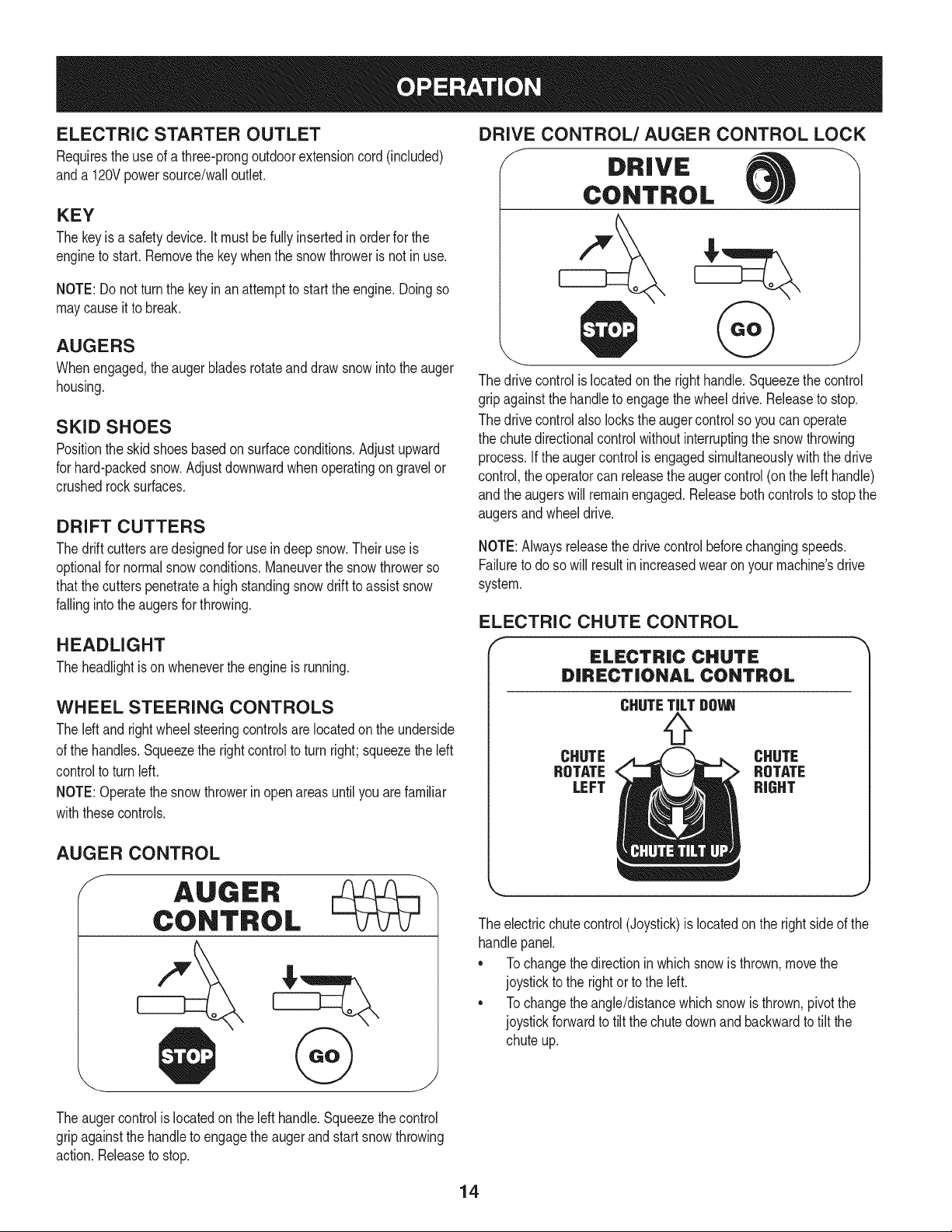
AUGER CONTROL
f
DRIVE CONTROL/AUGER CONTROL LOCK
f DRIVE
CONTROL
. @ .
The drivecontrolis locatedon the righthandle.Squeezethe control
gripagainstthe handleto engagethe wheeldrive.Releaseto stop.
The drivecontrolalso lockstheaugercontrolso youcan operate
the chutedirectionalcontrolwithoutinterruptingthe snowthrowing
process.If theauger controlis engagedsimultaneouslywiththedrive
control,theoperatorcan releasethe augercontrol(on the left handle)
andthe augerswill remainengaged.Releasebothcontrolsto stopthe
augersandwheeldrive.
NOTE:Alwaysreleasethedrivecontrolbeforechangingspeeds.
Failureto doso will resultin increasedwearonyour machine'sdrive
system.
ELECTRIC CHUTE CONTROL
f
ELECTRIC CHUTE
DiRECTiONAL CONTROL
CHUTE
ROTATE
LEFT
CHUTE
ROTATE
RIGHT
The electricchutecontrol(Joystick)is locatedon the rightside of the
handlepanel.
* Tochangethe directionin which snowis thrown,movethe
joystickto the rightor tothe left.
* Tochangethe angle/distancewhich snowis thrown,pivotthe
joystickforwardto tiltthe chutedownand backwardto tilt the
chuteup.
Theaugercontrolis locatedon the left handle.Squeezethecontrol
gripagainstthe handleto engagetheaugerand start snowthrowing
action.Releaseto stop.
14
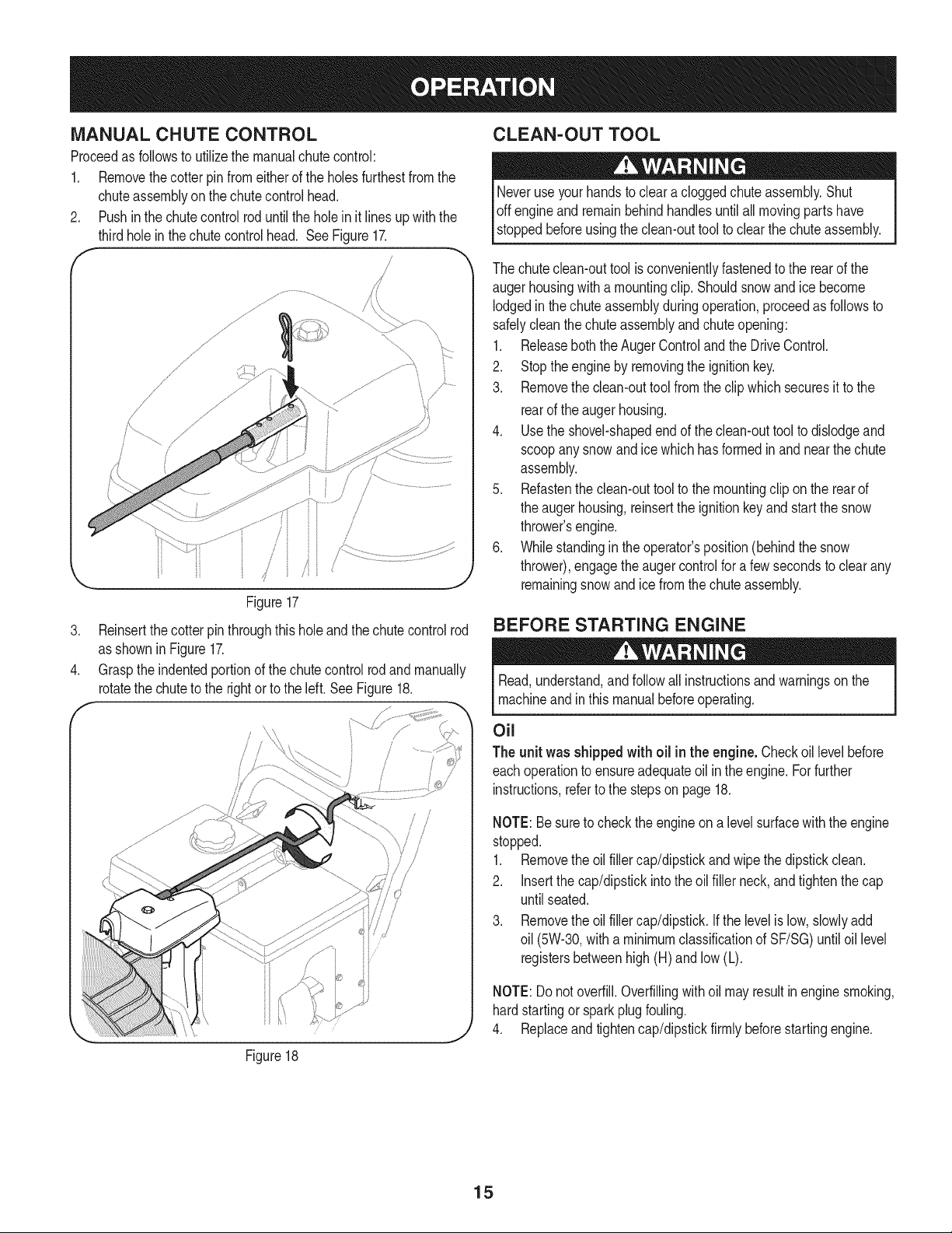
MANUAL CHUTE CONTROL
Proceedas followsto utilizethe manualchutecontrol:
1. Removethecotterpin fromeitherof the holesfurthestfromthe
chuteassemblyon the chutecontrol head.
2. Pushinthe chutecontrolroduntilthe holein it lines upwiththe
thirdholein thechute controlhead. See Figure17.
f
/
,/
............... i /
/
Figure17
3. Reinsertthe cotterpinthroughthis holeandthechutecontrolrod
as shownin Figure17.
4. Graspthe indentedportionof the chutecontrolrodandmanually
rotatethe chuteto the rightor to the left. SeeFigure18.
CLEAN-OUT TOOL
Neveruse yourhandsto cleara cloggedchuteassembly.Shut
Ioffengineand remainbehindhandlesuntilall movingparts have
[stoppedbeforeusingthe clean-outtoolto clearthe chuteassembly.
The chuteclean-outtool is convenientlyfastenedto the rearof the
augerhousingwith a mountingclip. Shouldsnowand ice become
lodgedinthe chute assemblyduringoperation,proceedas followsto
safelycleanthe chuteassemblyandchuteopening:
1. Releaseboththe AugerControlandthe DriveControl.
2. Stoptheengine by removingthe ignitionkey.
3. Removethe clean-outtool from the clipwhich securesit to the
rearof the augerhousing.
4. Usethe shovel-shapedendof the clean-outtoolto dislodgeand
scoopanysnowand ice whichhas formedin and nearthe chute
assembly.
5. Refastenthe clean-outtoolto the mountingclip on the rearof
the augerhousing,reinsertthe ignitionkeyand startthe snow
thrower'sengine.
6. Whilestandingin theoperator'sposition(behindthe snow
thrower),engagethe augercontrolfor a few secondsto clearany
remainingsnowand icefrom the chuteassembly.
BEFORE STARTING ENGINE
Read,understand,and followall instructionsandwarningson the
machineand in this manualbeforeoperating.
Figure18
/
/
/ /
i/
i//'
I
Oil
The unit was shippedwith oil in the engine.Checkoil levelbefore
eachoperationto ensureadequateoil in theengine.Forfurther
instructions,referto the stepsonpage 18.
NOTE:Besureto checkthe engineona levelsurfacewith theengine
stopped.
1. Removethe oilfiller cap/dipstickandwipe thedipstickclean.
2. insertthe cap/dipstickintothe oil filler neck,and tightenthe cap
untilseated.
3. Removethe oilfiller cap/dipstick,ifthe levelislow,slowlyadd
oil (5W-30,witha minimumclassificationof SF/SG)untiloil level
registersbetweenhigh (H) and low(L).
NOTE:Donot overfill.Overfillingwithoil mayresultinenginesmoking,
hardstartingor sparkplug fouling.
4. Replaceand tightencap/dipstickfirmly beforestartingengine.
15
Gasoline
Useautomotivegasoline(unleadedor low leadedto minimizecombus-
tionchamberdeposits)witha minimumof 87octane.Gasolinewith
upto 10%ethanolor 15%MTBE(MethylTertiaryButyl Ether)canbe
used.Neverusean oil/gasolinemixtureor dirty gasoline.Avoidgetting
dirt,dust,or waterinthefuel tank. DO NOTuse E85gasoline.
• Refuelin a well-ventilatedareawiththe engine stopped.Donot
smokeor allowflamesorsparksinthe areawheretheengineis
refueledor wheregasolineisstored.
• Do notoverfillthe fuel tank.Afterrefueling,makesurethe tank
cap is closedproperlyandsecurely.
• Becarefulnot to spillfuel when refueling.Spilledfuelor fuelvapor
mayignite.If any fuel isspilled,makesurethe area isdry before
startingtheengine.
• Avoidrepeatedor prolongedcontactwith skin or breathingof
vapor.
Useextremecare whenhandlinggasoline.Gasolineis extremely
flammableandthe vaporsare explosive.Neverfuelthe machine
indoorsorwhile theengineishotor running.Extinguishcigarettes,
cigars,pipesandother sourcesof ignition.
1. Cleanaroundfuelfill beforeremovingcap to fuel.
2. Afuel levelindicatorislocatedinthe fuel tank.See Figure15
inset.Becarefulnot to overfill.Filltankuntilfuel reachesthe fuel
levelindicatorto allow spacefor fuelexpansion.
STARTING THE ENGINE
>ressurizedstartingfluid. Vaporsare flammable.
NOTE:Allowtheengineto warmupfor a few minutesafter starting.
Theenginewill not developfull poweruntil it reachesoperating
temperatures.
Electric Starter
The optionalelectricstarteris equippedwitha groundedthree-wire
powercordandplug,and is designedto operateon 120volt AC
householdcurrent.It mustbe usedwith a properlygroundedthree-
prongreceptacleat all timesto avoidthe possibilityof electricshock.
Followall instructionscarefullyprior to operatingtheelectricstarter.
DONOTuse electricstarterinthe rain.
Determinethat yourhome'swiringis a three-wiregroundedsystem.
Aska licensedelectricianif you arenotcertain.
Ifyou havea groundedthree-prongreceptacle,proceedas follows.
Ifyou donot havethe properhousewiring,DONOT usethe electric
starterunderanyconditions.
1. Plugthe extensioncord intothe outletlocatedon the engine's
surface.Plugthe otherend of extensioncord intoa three-prong
120-volt,grounded,AC outletin a well-ventilatedarea.
2. Movethrottlecontrolto FAST(rabbit)_ position.
3. Movechoketo the CHOKEI,'1¢1position(coldenginestart).If
engineis warm,placechokein RUNposition.
4. Pushprimerthree(3) times,makingsureto cover vent hole in
primerbulbwhenpushing.Ifengine is warm,pushprimeronly
once.Alwayscovervent hole whenpushing.Cool weathermay
requireprimingto be repeated.
5. Pushstarterbuttonto startengine.Oncetheenginestarts,im-
mediatelyreleasestarterbutton.Electricstarteris equippedwith
thermaloverloadprotection;systemwill temporarilyshut-downto
allow starterto cool if electricstarterbecomesoverloaded.
6. As the enginewarms,slowlyrotatethechokecontrolto RUN
position.Ifthe enginefalters, restartengineand runwith choke
at half-chokepositionfor a shortperiod of time,and thenslowly
rotatethe chokeintoRUNposition.
7. Afterengineis running,disconnectpowercord fromelectric
starter.Whendisconnecting,alwaysunplugthe end at the wall
outletbeforeunpluggingthe oppositeend fromthe engine.
1. Makecertainboththe augercontrolanddrivecontrolare inthe
disengaged(released)position.
2. Insertkeyinto slot.Makesureit snapsinto place.Do notattempt
to turnthe key.
NOTE:The enginecannotstart withoutthe keyfully insertedintothe
ignitionswitch.
16
Recoil Starter
Do notpullthe starterhandlewhilethe enginerunning.
1. Movethrottlecontrolto FAST(rabbit)d_J_ position.
2. Movechoketo the CHOKEI#1 position(coldenginestart).If
engineis warm,placechokeinRUNposition.
3. Pushprimerthree (3)times,makingsureto coverventholewhen
pushing.Ifengine iswarm,push primeronlyonce. Alwayscover
ventholewhen pushing.Coolweathermay requireprimingto be
repeated.
4. Pullgentlyonthe starterhandleuntil itbeginsto resist,then
pullquicklyandforcefullyto overcomethe compression.Engine
shouldstart.Donot releasethe handleandallow itto snapback.
ReturnropeSLOWLYto originalposition.If required,repeatthis
step.
5. As theenginewarms,slowlyrotatethe chokecontrolto RUN
position.If the enginefalters,restartengineandrun with choke
at half-chokepositionfor a shortperiodof time,and then slowly
rotatethe chokeintoRUNposition.
To avoidunsupervisedengineoperation,neverleavethe machine
unattendedwiththe engine running.Turnthe engineoffafter use and
removekey.
NOTE: When selectinga DriveSpeed,use the slowerspeedsuntil
you arecomfortableandfamiliarwiththe operationof the snow
thrower.
2. Squeezethe drivecontrolagainstthe handleandthe snow
throwerwill move.Releaseitanddrive motionwill stop.
NOTE:NEVERrepositionthe shiftlever(changespeedsordirection
of travel)withoutfirst releasingthe drivecontrol and bringingthe snow
throwerto a completestop.Doingsowill resultinprematurewearto
the snowthrower'sdrivesystem.
TO ENGAGE AUGER
1. Toengagethe augerand startthrowingsnow,squeezethe auger
controlagainstthe left handle.Releaseto stopthe auger.
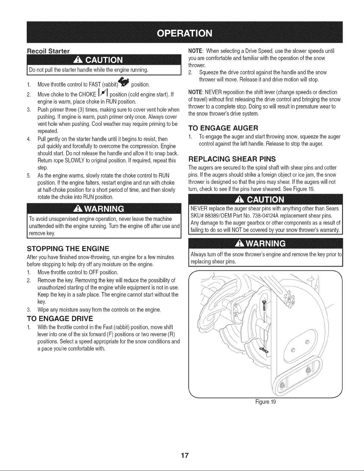
REPLACING SHEAR PINS
The augersare securedto the spiralshaftwith shearpins andcotter
pins.If the augersshouldstrikeaforeignobject or ice jam,the snow
throweris designedso thatthe pins mayshear.If theaugerswill not
turn,checkto see if the pins havesheared.SeeFigure19.
NEVERreplacethe augershearpinswithanythingotherthan Sears
SKU#88389/0EM PartNo. 738-04124Areplacementshearpins.
Anydamageto theaugergearboxor other componentsas a resultof
failingto do sowill NOTbecoveredbyyour snowthrower'swarranty.
STOPPING THE ENGINE
Afteryouhavefinishedsnow-throwing,runenginefora few minutes
beforestoppingto helpdry off any moistureon the engine.
1. Movethrottlecontrolto OFFposition.
2. Removethekey.Removingthe keywill reducethe possibilityof
unauthorizedstartingof the enginewhileequipmentis notin use.
Keepthe keyin a safe place.The enginecannotstart withoutthe
key.
3. Wipeany moistureawayfromthe controlson theengine.
TO ENGAGE DRIVE
1. Withthethrottlecontrolin the Fast(rabbit)position,moveshift
leverintooneof the six forward(F) positionsortwo reverse(R)
positions.Selecta speedappropriatefor the snowconditionsand
a paceyou'recomfortablewith.
Alwaysturn off thesnowthrower'sengineand removethe keypriorto
replacingshearpins.
J
Figure19
17
MAINTENANCE SCHEDULE
Beforeperforminganytype ofmaintenance/service,disengageall
controlsand stoptheengine.Waituntilallmovingpartshavecometo
acompletestop.Disconnectsparkplugwireandgroundit againstthe
enginetopreventunintendedstarting.Alwayswearsafetyglassesduring
operationor whileperforminganyadjustmentsorrepairs.
EachUseandevery 5
hours
1st5 hours
Annuallyor 25 hours
Annuallyor 50 hours
Annuallyor 100hours
BeforeStorage
1. Engineoil level
2. Looseor missinghardware
3. Unitandengine.
1. Engineoil
1. Sparkplug
2. Controllinkagesandpivots
3. Wheels
4. GearshaftandAugershaft
1. Engineoil
1. Sparkplug
1. Fuelsystem
Followthe maintenanceschedulegiven below.This chart describes
serviceguidelinesonly.Usethe ServiceLog columnto keeptrackof
completedmaintenancetasks.To locate the nearest Sears Service
Centeror to scheduleservice,simplycontactSearsat
1-800-4-MY-HOME®.
1. Check
2. Tightenor replace
3. Clean
1. Change
1. Check
2. Lubewithlight oil
3. Lubewithmultipurposeautogrease
4. Lubewithlight oil
1. Change
1. Change
1. Runengineuntilit stopsfromlack
d fuel
ENGINE MAINTENANCE
Checking Engine Oil
Beforelubricating,repairing,or inspecting,disengageall controls
Iandstop engine.Wait untilall movingpartshavecometo a complete
_stop.
NOTE: Checktheoil levelbeforeeachuseto besurecorrectoil level
is maintained.
Whenaddingoilto the engine,referto viscositychart below.Engine
oilcapacityis 1100ml (approx.37oz.). Donot over-fill.Usea 4-stroke,
oran equivalenthighdetergent,premiumquality motoroil certified
to meetorexceedU.S.automobilemanufacturer'srequirementsfor
serviceclassificationSG, SR MotoroilsclassifiedSG, SFwill show
thisdesignationonthe container.
1. Removethe oil fillercap/dipstickandwipethe dipstickclean.
2. Insertthe cap/dipstickintothe oilfiller neck,andtightenthe cap
until seated.
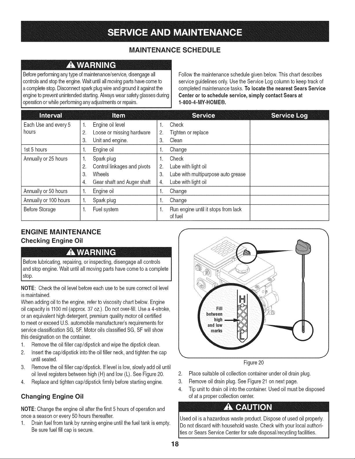
3. Removethe oil fillercap/dipstick.Iflevelis low,slowlyadd oiluntil
oil levelregistersbetweenhigh(H) andlow (L). SeeFigure20.
4. Replaceandtightencap/dipstickfirmlybeforestartingengine.
Changing Engine Oil
NOTE:Changethe engineoilafter the first5 hoursof operationand
oncea seasonorevery 50 hoursthereafter.
1. Drainfuelfromtankby runningengineuntilthe fuel tankis empty.
Besurefuel fill cap is secure.
J
Figure20
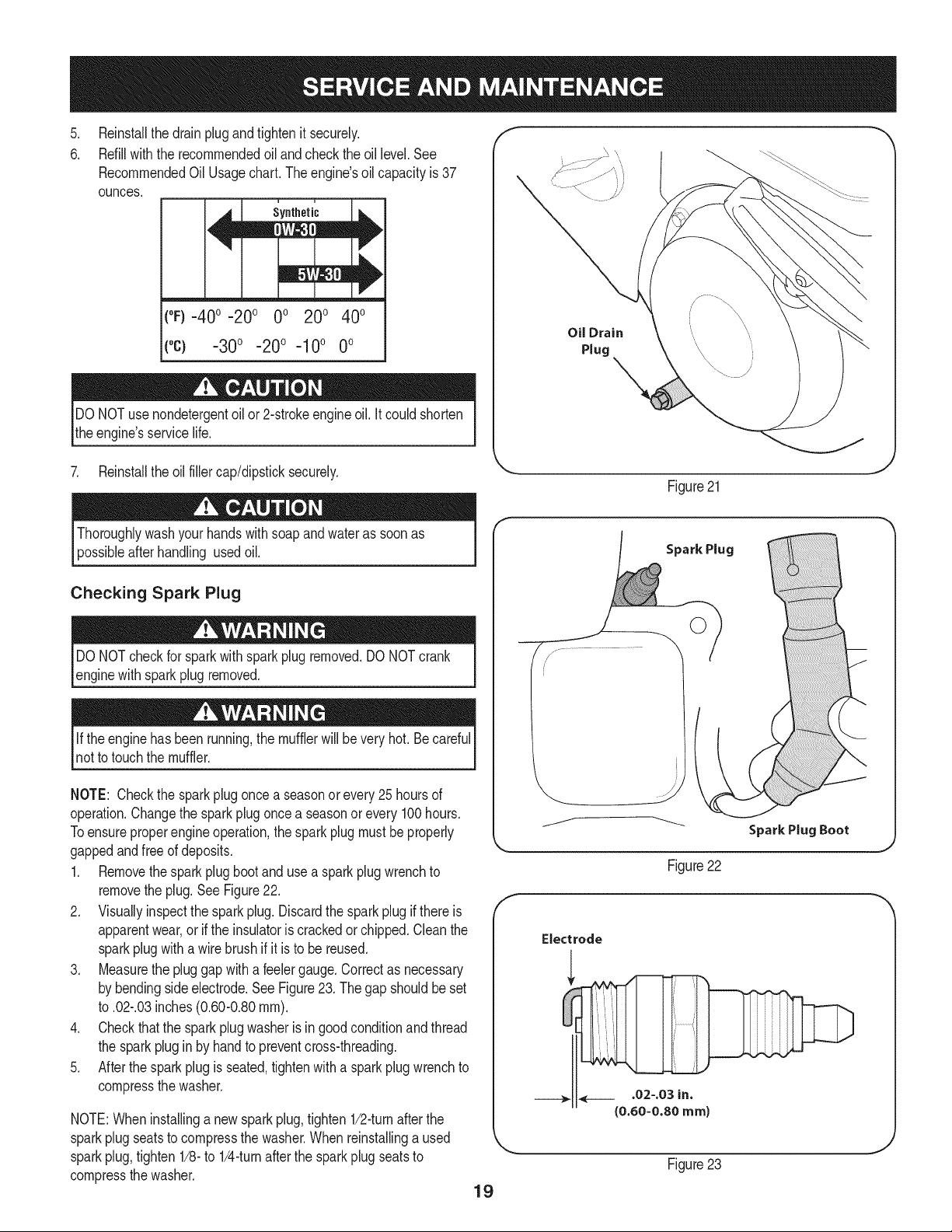
2. Placesuitableoil collectioncontainerunderoil drain plug.
3. Removeoil drain plug.See Figure21 on next page.
4. Tip unit to drainoil intothe container.Usedoil mustbedisposed
of at a propercollectioncenter.
Usedoil is a hazardouswasteproduct.Disposeof usedoil properly.
IDo notdiscardwithhouseholdwaste.Checkwithyour localauthori-
lties or SearsServiceCenterfor safedisposal/recyclingfacilities.
18
.
6.
Reinstallthe drainplugandtightenit securely.
Refillwiththe recommendedoil and checkthe oil level.See
RecommendedOil Usagechart.Theengine'soil capacityis 37
ounces.
i u
[
(%-40 °-20 o 0o 200 400
("c) -300 -200 -10° 0°
DO NOTuse nondetergentoilor 2-strokeengineoil. Itcould shorten
the engine'sservicelife.
Oil Drain
Plug
7. Reinstallthe oilfillercap/dipsticksecurely.
Figure21
Thoroughlywashyour handswithsoap andwater as soonas
possibleafterhandling usedoil.
Checking Spark Plug
DO NOTcheckfor sparkwithsparkplugremoved.DO NOTcrank
enginewith sparkplug removed.
Ifthe enginehas beenrunning,the mufflerwill bevery hot. Be careful
notto touchthe muffler.
NOTE: Checkthe sparkplugoncea seasonor every 25 hoursof
operation.Changethe sparkplugoncea seasonor every 100hours.
Toensureproperengineoperation,the sparkplug mustbe properly
gappedandfreeof deposits.
1. Removethesparkplug bootand use a sparkplug wrenchto
removethe plug.See Figure22.
2. Visuallyinspectthe sparkplug.Discardthe sparkplugif thereis
apparentwear,orif the insulatoris crackedor chipped.Cleanthe
sparkplugwith a wirebrush if it is to be reused.
3. Measurethe pluggapwitha feelergauge.Correctas necessary
by bendingsideelectrode.SeeFigure23. Thegap shouldbe set
to .02-.03inches(0.60-0.80ram).
4. Checkthatthe sparkplugwasheris ingoodconditionandthread
the sparkplugin by handto preventcross-threading.
5. Afterthesparkplugis seated,tightenwitha sparkplugwrenchto
compressthe washer.
NOTE:Wheninstallinga newsparkplug,tighten1/2-turnafter the
sparkplugseatsto compressthe washer.Whenreinstallinga used
sparkplug,tighten1/8-to 1/4-turnafter the sparkplug seatsto
compressthe washer.
19
Spark Plug
O
J
Figure22
Electrode
.02-.03 in.
{0.60-0.80 ram)
Figure23
hotandcan ine.
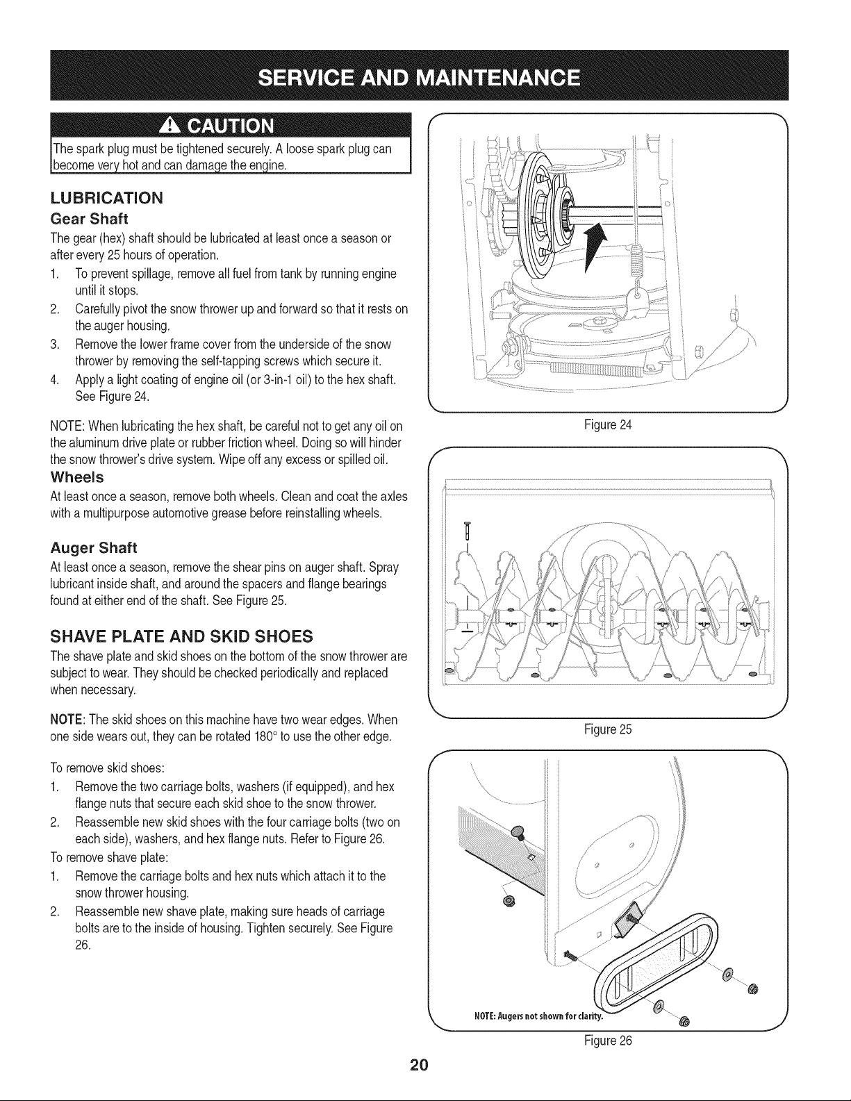
LUBRICATION
Gear Shaft
Thegear(hex)shaft shouldbe lubricatedat least oncea seasonor
afterevery25 hoursof operation.
1. Topreventspillage,removeall fuel fromtank by runningengine
until it stops.
2. Carefullypivotthe snowthrowerupandforwardso that it restson
theaugerhousing.
3. Removethe lowerframecoverfromthe undersideof the snow
throwerby removingthe self-tappingscrewswhichsecureit.
4. Applya lightcoatingof engineoil (or3-in-1oil) to the hexshaft.
SeeFigure24.
NOTE:Whenlubricatingthe hexshaft,be carefulnotto get any oil on
thealuminumdriveplateor rubberfrictionwheel. Doingsowill hinder
the snowthrower'sdrive system.Wipeoff anyexcessor spilledoil.
Wheels
At leastoncea season,removebothwheels.Cleanandcoat theaxles
witha multipurposeautomotivegreasebeforereinstallingwheels.
Auger Shaft
At leastoncea season,removethe shearpinson augershaft. Spray
lubricantinsideshaft,andaroundthe spacersand flangebearings
foundat eitherendof the shaft. See Figure25.
SHAVE PLATE AND SKID SHOES
The shaveplateand skid shoeson the bottomof the snowthrowerare
subjectto wear.Theyshouldbe checkedperiodicallyand replaced
whennecessary.
NOTE:Theskidshoeson this machinehavetwo wearedges.When
onesidewears out, theycan be rotated1800to usethe otheredge.
To removeskidshoes:
1. Removethe twocarriagebolts,washers(if equipped),andhex
flangenutsthat secureeach skid shoeto the snowthrower.
2. Reassemblenew skid shoeswiththe fourcarriagebolts(twoon
eachside),washers,and hex flangenuts.Referto Figure26.
To removeshaveplate:
1. Removethe carriageboltsand hexnutswhichattachit to the
snowthrowerhousing.
2. Reassemblenew shaveplate,makingsureheadsof carriage
boltsare to the insideof housing.Tightensecurely.SeeFigure
26.
)
// "?X
/ .... )
{;:7/
7/' ................
f
Figure24
Figure25
f
Figure26
2O
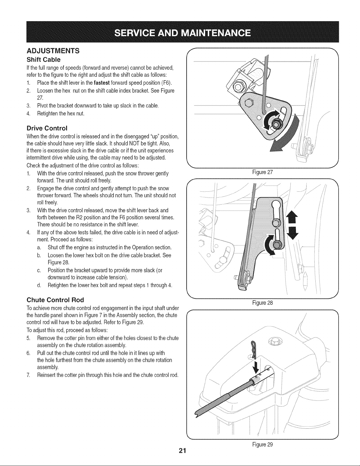
ADJUSTMENTS
Shift Cable
If thefull rangeof speeds(forwardandreverse)cannotbe achieved,
referto the figureto the rightandadjustthe shift cableas follows:
1. Placethe shiftleverin thefastest forwardspeedposition(F6).
2. Loosenthe hex nuton the shiftcable indexbracket.SeeFigure
27.
3. Pivotthe bracketdownwardto takeupslack inthe cable.
4. Retightenthehex nut.
Drive Control
Whenthedrivecontrolis releasedandin thedisengaged"up"position,
the cableshouldhaveverylittle slack.It shouldNOTbe tight. Also,
if thereis excessiveslackin thedrive cableor if the unitexperiences
intermittentdrivewhileusing,the cable mayneed to be adjusted.
Checktheadjustmentof the drivecontrolas follows:
1. Withthedrivecontrolreleased,pushthe snowthrowergently
forward.The unitshouldrollfreely.
2. Engagethe drivecontrolandgentlyattemptto pushthe snow
throwerforward.Thewheelsshouldnotturn.The unitshouldnot
rollfreely.
3. Withthedrivecontrolreleased,movethe shift leverbackand
forthbetweenthe R2positionand the F6 positionseveraltimes.
Thereshouldbeno resistancein the shiftlever.
4. If anyof the abovetestsfailed,the drivecable is in needof adjust-
ment.Proceedas follows:
a. Shutoff theengineas instructedinthe Operationsection.
b. Loosenthe lowerhexbolt onthe drivecable bracket.See
Figure28.
c. Positionthe bracketupwardto providemoreslack(or
downwardto increasecabletension).
d. Retightenthe lowerhex boltand repeatsteps1 through4.
J
Figure27
f
.........
Chute Control Rod
Toachievemorechutecontrolrodengagementin the input shaftunder
the handlepanelshownin Figure7 in the Assemblysection,the chute
controlrodwill haveto beadjusted.Referto Figure29.
Toadjustthis rod,proceedas follows:
5. Removethecotterpin fromeitherof the holesclosestto thechute
assemblyon thechuterotationassembly.
6. Pulloutthe chutecontrolroduntilthe holein it lines upwith
the holefurthestfromthe chute assemblyon the chute rotation
assembly.
7. Reinsertthe cotterpinthroughthis holeandthechutecontrolrod.
Figure28
.......,f
Figure29
21
Auger Control f ;.... "_
Referto the Assemblysectionfor instructionson adjustingtheauger
controlcable.
Skid Shoes
Referto the Assemblysectionfor instructionson adjustingthe skid
shoes.
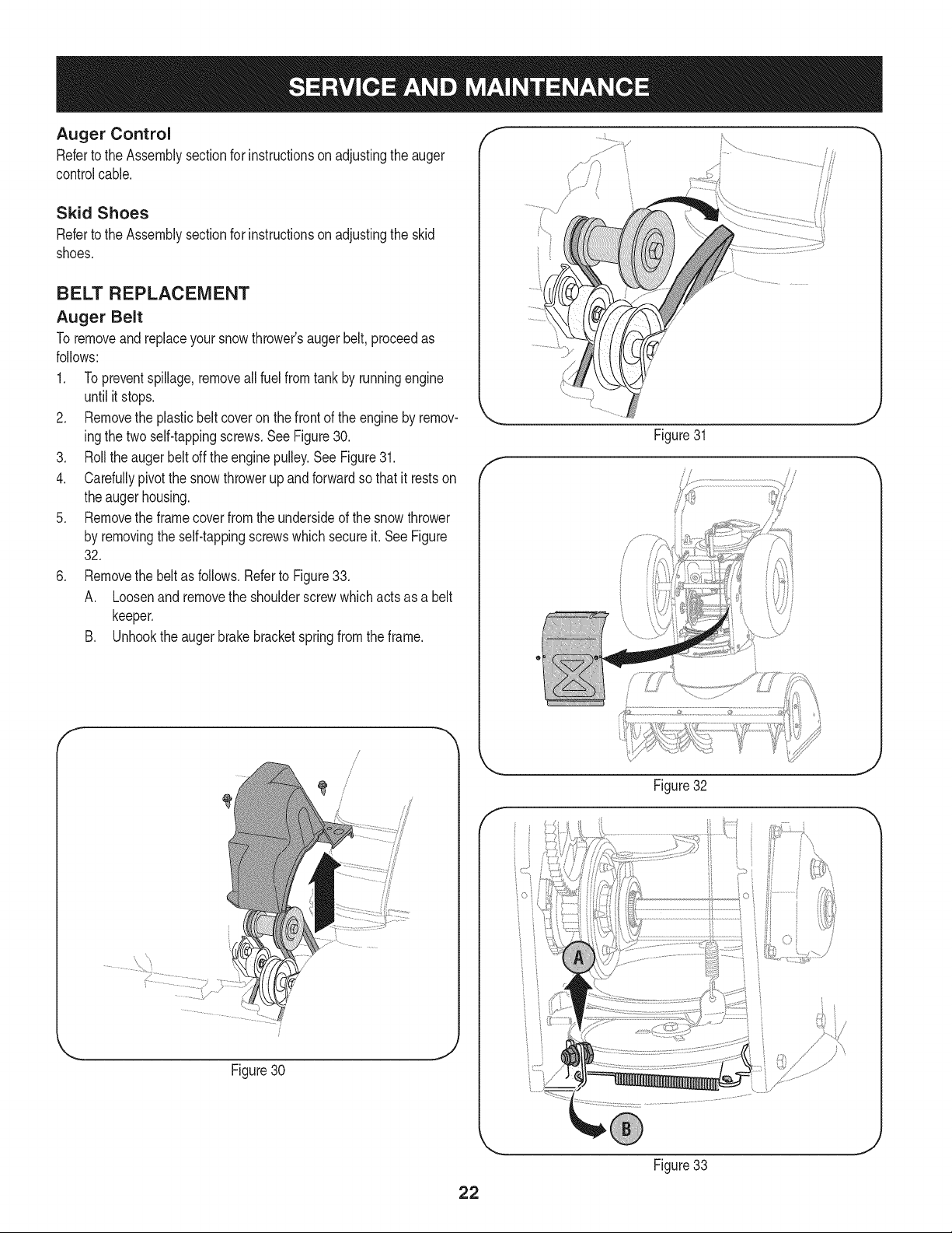
BELT REPLACEMENT
Auger Belt
To removeandreplaceyoursnowthrower'saugerbelt,proceedas
follows:
1. Topreventspillage,removeall fuel fromtank by runningengine
until itstops.
2. Removethe plasticbelt coveronthe frontof the engineby remov-
ingthe twoself-tappingscrews.See Figure30.
3. Rollthe augerbeltoff theenginepulley.See Figure31.
4. Carefullypivotthe snowthrowerupandforwardso that itrestson
theaugerhousing.
5. Removethe framecoverfromthe undersideof the snow thrower
by removingthe self-tappingscrewswhich secureit. See Figure
32.
6. Removethe beltas follows.Referto Figure33.
A. Loosenand removethe shoulderscrewwhichactsas a belt
keeper.
B. Unhookthe augerbrakebracketspringfrom the frame.
f
Figure30
Figure31
J
J
f
Figure32
22
Figure33
J
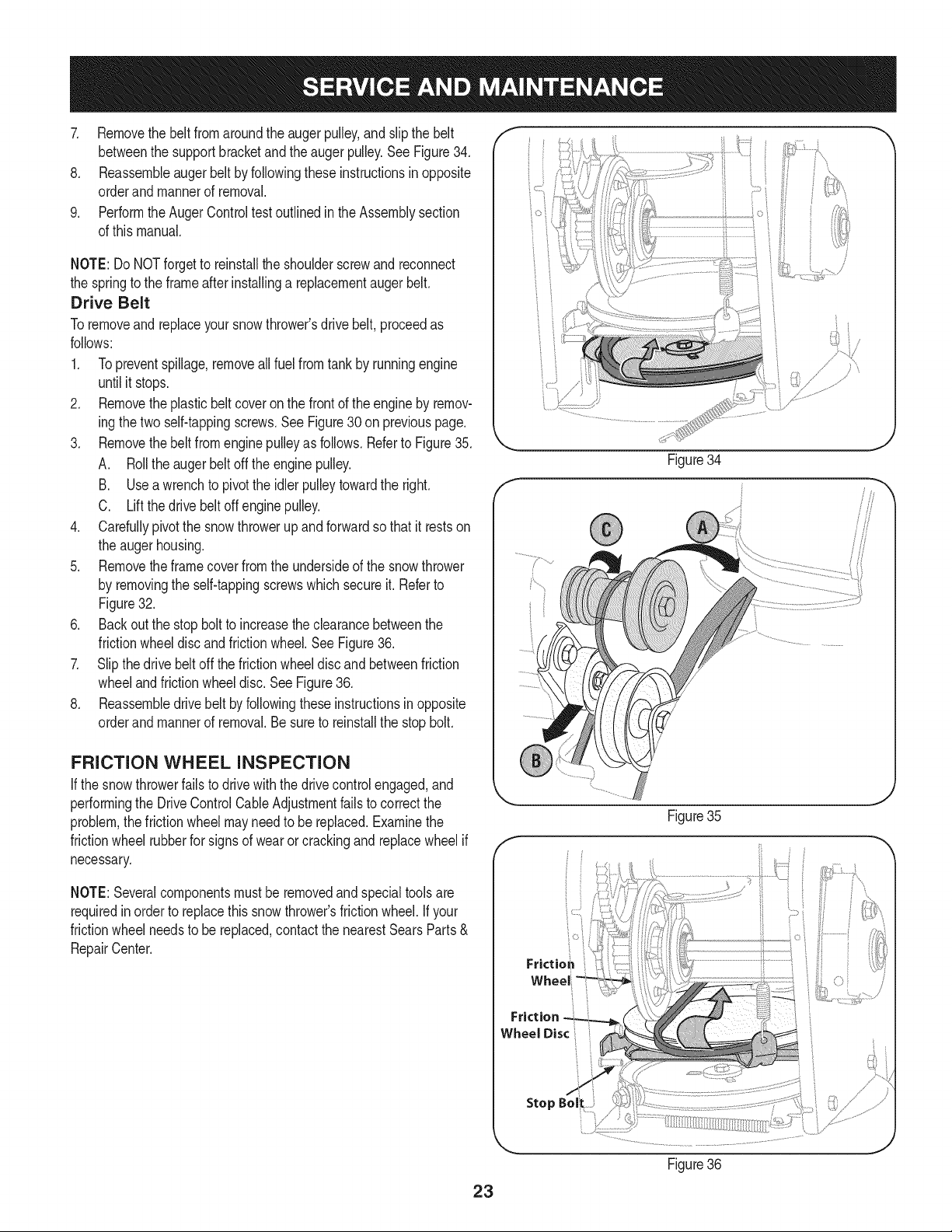
7. Removethebeltfromaroundtheaugerpulley,andslipthebelt
betweenthesupportbracketandtheaugerpulley.SeeFigure34.
8. Reassembleaugerbeltbyfollowingtheseinstructionsinopposite
orderandmannerofremoval.
9. PerformtheAugerControltestoutlinedintheAssemblysection
ofthismanual.
NOTE:DoNOTforgettoreinstalltheshoulderscrewandreconnect
thespringtotheframeafterinstallingareplacementaugerbelt.
Drive Belt
Toremoveand replaceyoursnowthrower'sdrivebelt,proceedas
follows:
1. Topreventspillage,removeallfuel fromtank by runningengine
untilit stops.
2. Removetheplasticbelt coveronthe frontof the engineby remov-
ingthe twoself-tappingscrews.See Figure30 on previouspage.
3. Removethebelt fromenginepulleyas follows.Referto Figure35.
A. Rollthe augerbeltoff theenginepulley.
B. Useawrenchto pivotthe idlerpulleytowardthe right.
C. Liftthe drivebelt offenginepulley.
4. Carefullypivotthe snowthrowerupand forwardsothat itrestson
the augerhousing.
5. Removetheframecoverfromthe undersideof the snowthrower
by removingthe self-tappingscrewswhich secureit. Referto
Figure32.
6. Backoutthe stopbolt to increasethe clearancebetweenthe
frictionwheeldiscandfrictionwheel.See Figure36.
7. Slipthe drivebelt offthe frictionwheeldiscandbetweenfriction
wheelandfrictionwheeldisc.See Figure36.
8. Reassembledrive beltby followingthese instructionsinopposite
orderand mannerof removal.Besureto reinstallthe stopbolt.
FRICTION WHEEL INSPECTION
If the snowthrowerfailsto drivewith thedrivecontrolengaged,and
performingthe DriveControlCableAdjustmentfailsto correctthe
problem,the frictionwheelmayneedto be replaced.Examinethe
frictionwheelrubberfor signsof wearor crackingand replacewheelif
necessary.
NOTE:Severalcomponentsmustbe removedandspecialtools are
requiredinorder to replacethis snowthrower'sfrictionwheel.Ifyour
frictionwheelneedsto bereplaced,contactthe nearestSearsParts&
RepairCenter.
iO i
Figure34
///
f
Figure35
J
Frictio_
Friction
Wheel Disc
Stop
Figure36
23
Ifthe snowthrowerwillnot be usedfor30 daysor longer,or if it is the end of the snowseasonwhenthe last possibilityof snowis gone,the
equipmentneedsto bestoredproperly.Followstorageinstructionsbelowto ensuretop performancefromthe snowthrowerfor manymoreyears.
PREPARING ENGINE
Enginesstoredover30days need to be drainedof fuel to prevent
deteriorationandgumfrom formingin fuel systemor on essential
carburetorparts.If thegasolinein yourenginedeterioratesduring
storage,youmayneedto havethe carburetor,andotherfuel system
components,servicedor replaced.
1. Removeall fuel fromtank by runningengineuntil it stops.Donot
attemptto pourfuel fromthe engine.
2. Changethe engineoil.
3. Removesparkplugandpourapproximately1oz.(30 rnl)of clean
engineoil intothe cylinder.Pullthe recoilstarterseveraltimesto
distributetheoil, and reinstallthe sparkplug.
4. Cleandebrisfromaroundengine,andunder,around,andbehind
muffler.Applya lightfilmof oilon anyareasthatare susceptible
to rust.
• Storeina clean,dry and wellventilatedareaawayfrom anyap-
pliancethatoperateswith a flame or pilotlight, such as a furnace,
waterheater,or clothesdryer.Avoidany areawith a spark
producingelectricmotor,or wherepowertools are operated.
Neverstoresnowthrowerwith fuel in tank indoorsor in poorlyventi-
latedareas,wherefuel fumesmayreachan openflame,spark or pilol
lightas ona furnace,waterheater,clothesdryer or gas appliance.
• If possible,avoidstorageareaswithhigh humidity.
• Keepthe enginelevelin storage.Tiltingcan causefuel or oil
leakage.
PREPARING SNOW THROWER
Whenstoringthe snowthrowerin an unventilatedormetal stor-
age shed,careshouldbe taken to rustprooftheequipment.Using
a light oilor silicone,coattheequipment,especiallyanychains,
springs,bearingsandcables.
• Removealldirt fromexteriorof engineand equipment.
• Followlubricationrecommendations.
• Storeequipmentin a clean,dry area.
• Inflatethe tiresto the maximumPSi. Referto tiresidewall.
24
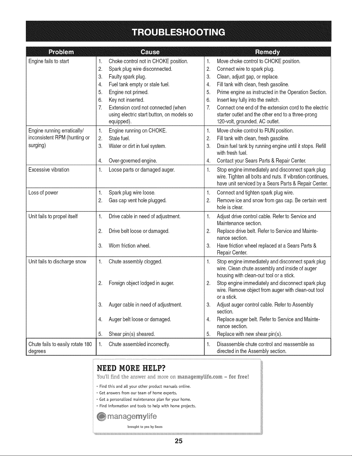
Enginefailsto start
Enginerunningerratically/
inconsistentRPM(huntingor
surging)
Excessivevibration
Lossof power
Unitfailsto propelitself
Unitfailsto dischargesnow
1. Chokecontrolnot inCHOKEposition.
2. Sparkplugwire disconnected.
3. Faultysparkplug.
4. Fueltankemptyor stalefuel.
5. Enginenot primed.
6. Keynot inserted.
7. Extensioncordnot connected(when
usingelectricstartbutton,on modelsso
equipped).
1. EnginerunningonCHOKE.
2. Stalefuel.
3. Waterordirt infuel system.
4. Over-governedengine.
1. Loosepartsor damagedauger.
1. Sparkplugwire loose.
2. Gascap ventholeplugged.
1. Drivecable inneedof adjustment.
2. Drivebelt looseor damaged.
3. Wornfrictionwheel.
1. Chuteassemblyclogged.
2. Foreignobjectlodgedin auger.
3. Augercablein needof adjustment.
4. Augerbelt looseordamaged.
5. Shearpin(s) sheared.
1. Chuteassembledincorrectly.
1. Movechokecontrolto CHOKEposition.
2. Connectwireto sparkplug.
3. Clean,adjustgap,or replace.
4. Filltankwith clean,freshgasoline.
5. Primeengineas instructedinthe OperationSection.
6. Insertkeyfully intothe switch.
7. Connectoneendof the extensioncordto the electric
starteroutletandthe otherend to a three-prong
120-volt,grounded,ACoutlet.
1. Movechokecontrolto RUNposition.
2. Filltankwith clean,freshgasoline.
3. Drainfueltankby runningengineuntil it stops.Refill
withfreshfuel.
4. ContactyourSearsParts& RepairCenter.
1. Stopengineimmediatelyand disconnectsparkplug
wire.Tightenall boltsand nuts.If vibrationcontinues,
haveunit servicedbya SearsParts& RepairCenter.
1. Connectandtightensparkplugwire.
2. Removeiceand snowfromgascap. Becertainvent
holeis clear.
1. Adjustdrivecontrolcable.Referto Serviceand
Maintenancesection.
2. Replacedrive belt.Referto Serviceand Mainte-
nancesection.
3. Havefrictionwheelreplacedat a SearsParts&
RepairCenter.
1. Stopengineimmediatelyand disconnectsparkplug
wire.Cleanchuteassemblyand insideof auger
housingwithclean-outtoolor a stick.
2. Stopengineimmediatelyand disconnectsparkplug
wire.Removeobjectfrom augerwith clean-outtool
ora stick.
3. Adjustaugercontrolcable.Referto Assembly
section.
4. Replaceaugerbelt.Referto Serviceand Mainte-
nancesection.
5. Replacewith newshearpin(s).
Chutefailsto easily rotate 180 1. Disassemblechutecontroland reassembleas
degrees directedinthe Assemblysection.
NEED HORE HELP?
Yot,Fttfind. th_ answer a!ld mo_e on ma_age_y_ifeocom _ for free]
Find this and att your other product manua[s ontine.
Get answers from our team of home experts.
Get a personalized maintenance p[an for your home.
Find information and tools to he[p with home projects.
managemylife
b_e'_g_t_/_eyeu by Sea_s
25
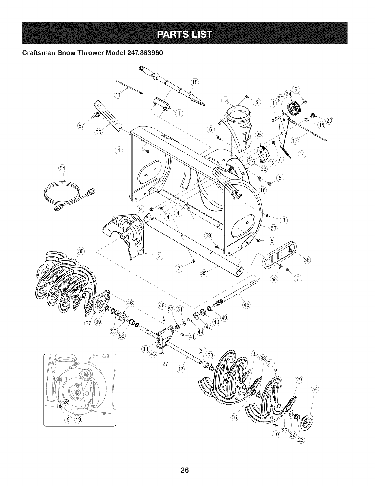
Craftsman Snow Thrower Model 247.883960
/
/
/
26
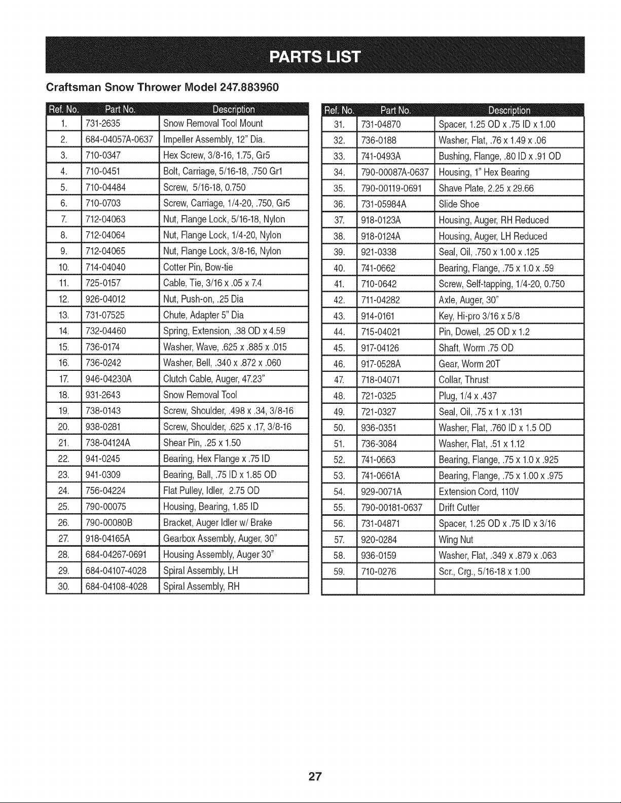
Craftsman Snow Thrower IViodel 247.883960
D = 0 0
731-2635 SnowRemovalToolMount
2. 684-04057A-0637 ImpellerAssembly,12"Dia.
3. L710-0347 LHexScrew,3/8-16, 1.75,Gr5
4. 710-0451 Bolt,Carriage,5/16-18,.750Grl
5. 710-04484 Screw, 5/16-18,0.750
6. 710-0703 Screw,Carriage,1/4-20,.750,Gr5
7. 712-04063 Nut, FlangeLock,5/16-18,Nylon
8. 712-04064 Nut, FlangeLock,1/4-20,Nylon
9. 712-04065 Nut, FlangeLock,3/8-16,Nylon
10. 714-04040 CotterPin,Bow-tie
11. J 725-0157 l Cable,Tie, 3/16x .05x 7.4
12. 926-04012 Nut, Push-on,.25 Dia
13. 731-07525 Chute,Adapter5" Dia
14. 732-04460 Spring,Extension,.38OD x 4.59
15. 736-0174 Washer,Wave,.625x .885x .015
16. 736-0242 Washer,Bell, .340x .872x .060
17. 946-04230A ClutchCable,Auger,47.23"
18. 931-2643 SnowRemovalTool
19. 738-0143 Screw,Shoulder,.498x .34,3/8-16
L
20. 938-0281 Screw,Shoulder,.625x .17,3/8-16
21. 738-04124A ShearPin, .25x 1.50
22. 941-0245 Bearing,Hex Flangex .75ID
23. 941-0309 Bearing,Ball,.75 ID x 1.85OD
24. 756-04224 Flat Pulley,Idler, 2.75OD
25. 790-00075 Housing,Bearing,1.85ID
26. 790-00080B Bracket,Auger Idlerw/Brake
27. 918-04165A GearboxAssembly,Auger,30"
28. 684-04267-0691 HousingAssembly,Auger30"
29. 684-04107-4028 SpiralAssembly,LH
30. 684-04108-4028 SpiralAssembly,RH
731-04870
32. 736-0188
33. 741-0493A
34. 790-00087A-0637
35. 790-00119-0691
36. 731-05984A
D = O O
Spacer,1.25OD x .75IDx 1.00
Washer,Flat,.76x 1.49x .06
Bushing,Flange,.80ID x .91OD
Housing,1"HexBearing
ShavePlate,2.25 x 29.66
SlideShoe
37. 918-0123A
38. 918-0124A
39. 921-0338
40. 741-0662
41. 710-0642
42. 711-04282
43. 914-0161
44. 715-04021
Housing,Auger,RH Reduced
Housing,Auger,LH Reduced
Seal,Oil, .750x 1.00x .125
Bearing,Flange,.75x 1.0x .59
Screw,Self-tapping,1/4-20,0.750
Axle,Auger,30"
Key,Hi-pro3/16x 5/8
Pin, Dowel,.25 ODx 1.2
45.
917-04126 Shaft,Worm.75OD
46. 917-0528A Gear,Worm20T
47. 718-04071 Collar,Thrust
48. 721-0325 Plug, 1/4x .437
49. 721-0327 Seal,Oil, .75x 1x .131
50. 936-0351 Washer,Flat,.760IDx 1.50D
51. 736-3084 Washer,Flat,.51x 1.12
52. 741-0663 Bearing,Flange,.75x 1.0x .925
53. 741-0661A Bearing,Flange,.75x 1.00x .975
54. 929-0071A ExtensionCord,110V
55. 790-00181-0637 Drift Cutter
56. 731-04871 Spacer,1.25OD x .75IDx 3/16
57. 920-0284 Wing Nut
58. 936-0159 Washer,Fiat,.349x .879x .063
59. 710-0276 Scr.,Crg.,5/16-18x 1.00
27
Craftsman Snow Thrower Model 247.883960 _o_19_. _i/.o_
28
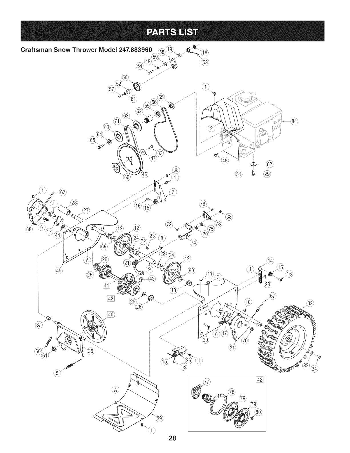
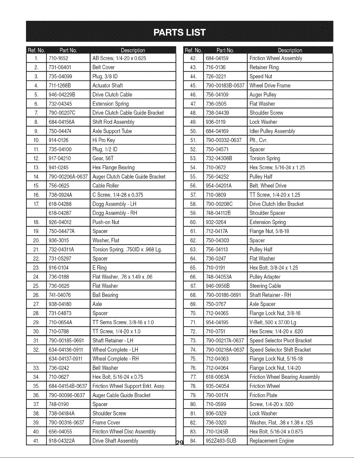
42i
/
D_ i B O ¸
710-1652 ABScrew,1/4-20x 0.625
2. 731-06401 BeltCover
3. 735-04099 Plug,3/8 ID
4. 711-1268B ActuatorShaft
5. 946-04229B DriveClutchCable
6. 732-04345 ExtensionSpring
7. 790-002070 DriveClutchCableGuideBracket
8. 684-04156A ShiftRodAssembly
9. 750-04474 AxleSupportTube
10. 914-0126 Hi ProKey
11. 735-04100 Plug,1/2 ID
12. 917-04210 Gear,56T
13. 941-0245 HexFlangeBearing
14. 790-00206A-0637 AugerClutchCableGuideBracket
15. 756-0625 CableRoller
16. 738-0924A C Screw,1/4-28x 0.375
17. 618-04288 DoggAssembly-LH
618-04287 DoggAssembly-RH
18. 926-04012 Push-onNut
19. 750-04477A Spacer
20. 936-3015 Washer,Fiat
21. 732-04311A TorsionSpring,.7501Dx .968 Lg.
22. 731-05297 Spacer
23. 916-0104 E Ring
24. 736-0188 FiatWasher,.76x 1.49x .06
25. 736-0626 FiatWasher
26. 741-04076 BallBearing
27. 938-04180 Axle
28. 731-04873 Spacer
29. 710-0654A TTSeresScrew,3/8-16x 1.0
30. 710-0788 TTScrew,1/4-20x 1.0
31. 790-00185-0691
32. 634-04136-0911
634-04137-0911
33. 736-0242
34. 710-0627
35. 684-04154B-0637
36. 790-00096-0637
ShaftRetainer- LH
WheelComplete-LH
WheelComplete-RH
BellWasher
HexBolt,5/16-24x 0.75
FrictionWheelSupportBrkt.Assy.
AugerCableGuideBracket
37. L7480190 Spacer
38. 738-04184A ShoulderScrew
39. 790-00316-0637 FrameCover
40. 656-04055 FrictionWheelDiscAssembly
41. 918-04322A DriveShaft Assembly
m _ O
684-04159 FrictionWheelAssembly
43. 716-0136 RetainerRing
44. 726-0221 Speed Nut
45. 790-00183B-0637 WheelDriveFrame
46. 756-04109 AugerPulley
47. 736-0505 FiatWasher
48. 738-04439 ShoulderScrew
49. 936-0119 LockWasher
50. 684-04169 IdlerPulleyAssembly
51. 790-00332-0637 Pit.,Cvr.
52. 750-04571 Spacer
53. 732-04308B TorsionSpring
54. 710-0672 HexScrew,5/16-24x 1.25
55. 756-04252 PulleyHalf
56. 954-04201A Belt,WheelDrive
57. 710-0809 TT Screw,1/4-20x 1.25
58. 790-002080 DriveClutchIdlerBracket
59. 748-04112B ShoulderSpacer
60. 932-0264 ExtensionSpring
61. 712-0417A FlangeNut,5/8-18
62. 750-04303 Spacer
63. 756-04113 PulleyHalf
64. 736-0247 FiatWasher
65. 710-0191 HexBolt,3/8-24x 1.25
66. 748-04053A PulleyAdapter
67. 946-0956B SteeringCable
68. 790-00186-0691 ShaftRetainer- RH
69. 750-0767 Axle Spacer
70. 712-04065 FlangeLockNut,3/8-16
71. 954-04195 V-Belt,.500x 37.00Lg
72. 710-0751 HexScrew,1/4-20x .620
73. 790-00217A-0637 SpeedSelectorPivotBracket
74. 790-00218A-0637 SpeedSelectorShiftBracket
75. 712-04063 FlangeLockNut,5/16-18
76. 712-04064 FlangeLockNut, 1/4-20
77. 618-0063A FrictionWheelBearingAssembly
78. 935-04054 FrictionWheel
79. 790-00174 FrictionPlate
80. 710-0599 Screw,1/4-20x .500
81. 936-0329 LockWasher
82. 736-0320 Washer,Fiat,.38x 1.38x .125
83. 710-1245B HexBolt,5/16-24x 0.875
84. 952Z483-SUB ReplacementEngine
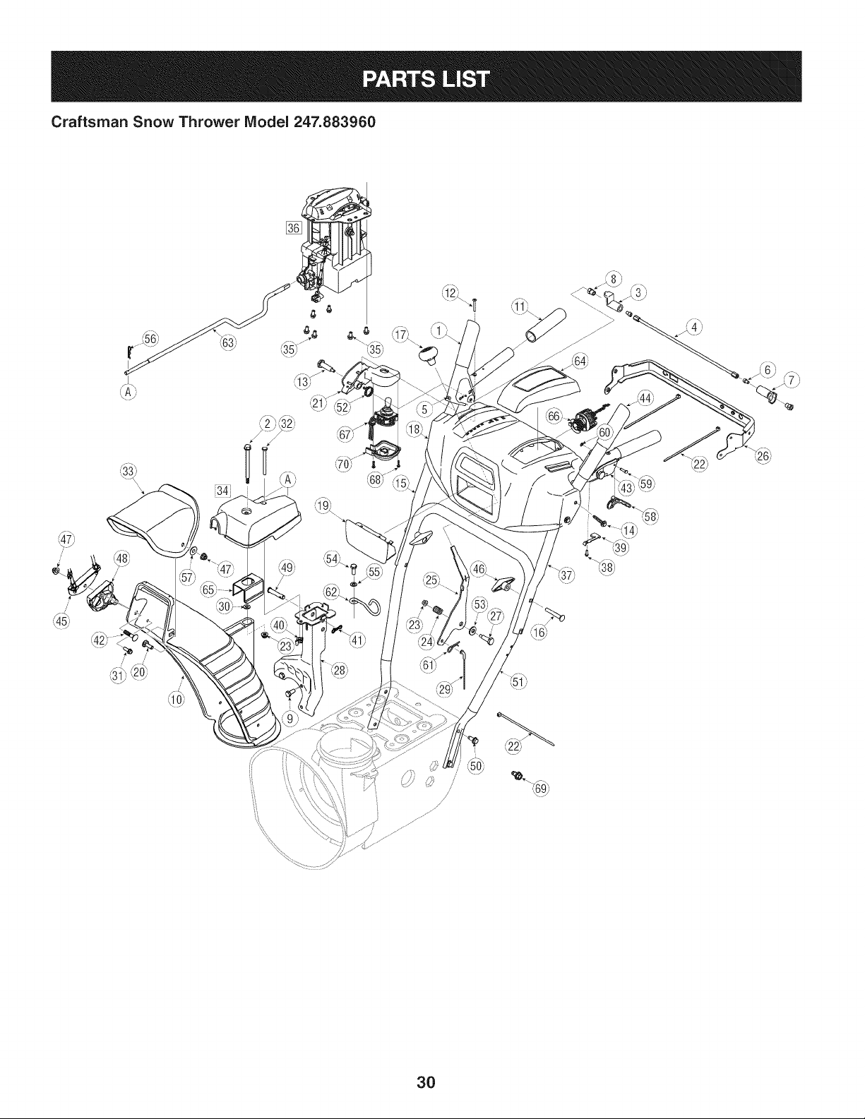
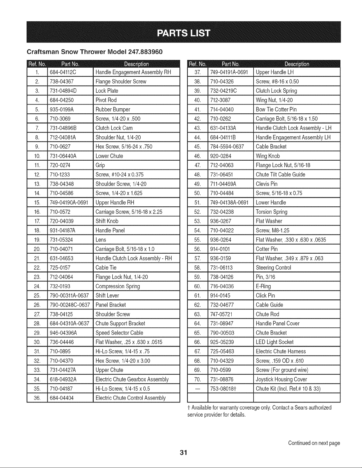
Craftsman Snow Thrower Model 247.883960
[]
/
/
i /
3O
Craftsman Snow Thrower IViodel 247.883960
684-04112C HandleEngagementAssemblyRH
2. 738-04367 FlangeShoulderScrew
3. 731-04894D LockPlate
4. 684-04250 PivotRod
5. 935-0199A RubberBumper
6. L710-3069 _ Screw,1/4-20x .500
7. 731-04896B ClutchLockCam
8. 712-04081A ShoulderNut, 1/4-20
9. 710-0627 HexScrew,5/16-24x .750
10. 731-06440A LowerChute
11. 720-0274 Grip
12. 710-1233 Screw,#10-24x 0.375
13. 738-04348 ShoulderScrew,1/4-20
14. 710-04586 Screw,1/4-20x 1.625
15. 749-04190A-0691 UpperHandleRH
16. 710-0572 CarriageScrew,5/16-18x 2.25
17. 720-04039 Shift Knob
18. 931-04187A HandlePanel
19. 731-05324 Lens
20. 710-04071 CarriageBolt,5/16-18x 1.0
21. 631-04653 HandleClutchLockAssembly- RH
22. 725-0157 CableTie
23. 712-04064 FlangeLock Nut, 1/4-20
24. 732-0193 CompressionSpring
25. 790-00311A-0637 ShiftLever
26. 790-00248C-0637 PanelBracket
27. 738-04125 ShoulderScrew
28. 684-04310A-0637 ChuteSupportBracket
29. 946-04396A SpeedSelectorCable
30. .736-04446 Flat Washer,.25x .630x .0515
31. 710-0895 Hi-LoScrew,1/4-15x .75
32. 710-04370 HexScrew,1/4-20x 3.00
33. L731-04427A LUpperChute
34. 618-04932A ElectricChuteGearboxAssembly
35. 710-04187 Hi-LoScrew,1/4-15x 0.5
36. 684-04404 ElectricChuteControlAssembly
D = O O
749-04191A-0691 UpperHandleLH
38. 710-04326 Screw,#8-16x 0.50
39. 732-04219C ClutchLock Spring
40. 712-3087 Wing Nut, 1/4-20
41. 714-04040 BowTie CotterPin
42. 710-0262 CarriageBolt,5/16-18x 1.50
43. 631-04133A HandleClutchLockAssembly- LH
44. 684-04111B HandleEngagementAssemblyLH
45. 784-5594-0637 Cable Bracket
46. 920-0284 Wing Knob
47. 712-04063 FlangeLock Nut,5/16-18
48. 731-06451 ChuteTilt CableGuide
49. 711-04469A ClevisPin
50. 710-04484 Screw,5/16-18x 0.75
51. 749-04138A-0691 LowerHandle
52. 732-04238 TorsionSpring
53. 936-0267 FiatWasher
54. 710-04022 Screw,M8-1.25
55. 936-0264 FiatWasher,.330x .630x .0635
56. 914-0101 Cotter Pin
57. 936-0159 FiatWasher,.349x .879x .063
58. 731-06113 SteeringControl
59. 738-04126 Pin,3/16
60. 716-04036 E-Ring
61. 914-0145 Click Pin
62. 732-04677 CableGuide
63. 747-05721 Chute Rod
64. 731-08947 HandlePanelCover
65. 790-00503 Chute Bracket
66. 925-05239 LEDLightSocket
67. 725-05463
68. 710-04329
69. 710-0599
70. 731-08876
-- 753-08018¢
ElectricChuteHarness
Screw,.159ODx .610
Screw(Forgroundwire)
JoystickHousingCover
ChuteKit (Incl.Ref.#10& 33)
t- Availablefor warrantycoverageonly.Contacta Searsauthorized
serviceproviderfor details.
31
Continuedon next page
Craftsman Snow Thrower IViodel 247.883960
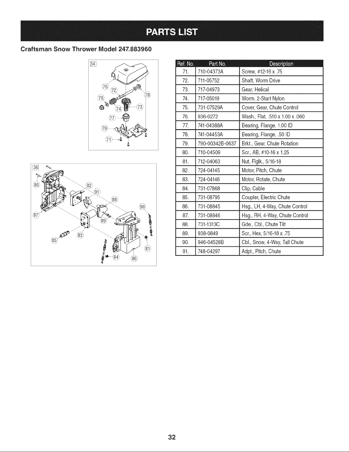
[]
i 7 ¸ • _
D = 0 0
710-04373A Screw,#12-16x .75
72. 711-05752 Shaft,WormDrive
73. 717-04973 Gear,Helical
74. 717-05019 Worm,2-Start Nylon
75. 731-07529A Cover,Gear,ChuteControl
76. 936-0272 Wash.,Flat,.510x 1.00x .060
77. 741-04388A Bearing,Flange,1.00ID
78. 741-04453A Bearing,Flange,.50 ID
79. 790-00342B-0637 Brkt.,Gear,ChuteRotation
80. 710-04509 Scr.,AB, #10-16x 1.25
81. 712-04063 Nut, Flgik.,5/16-18
82. 724-04145 Motor,Pitch,Chute
83. 724-04146 Motor,Rotate,Chute
84. 731-07868 Clip, Cable
85. 731-08795 Coupler,ElectricChute
86. 731-08845 Hsg., LH,4-Way,ChuteControl
87. 731-08846 Hsg., RH,4-Way,ChuteControl
88. 731-1313C Gde.,Cbl.,ChuteTilt
89. 938-0849 Scr.,Hex,5/16-18x .75
90. 946-04528B Cbl.,Snow,4-Way,TallChute
91. 748-04297 Adpt.,Pitch,Chute
32
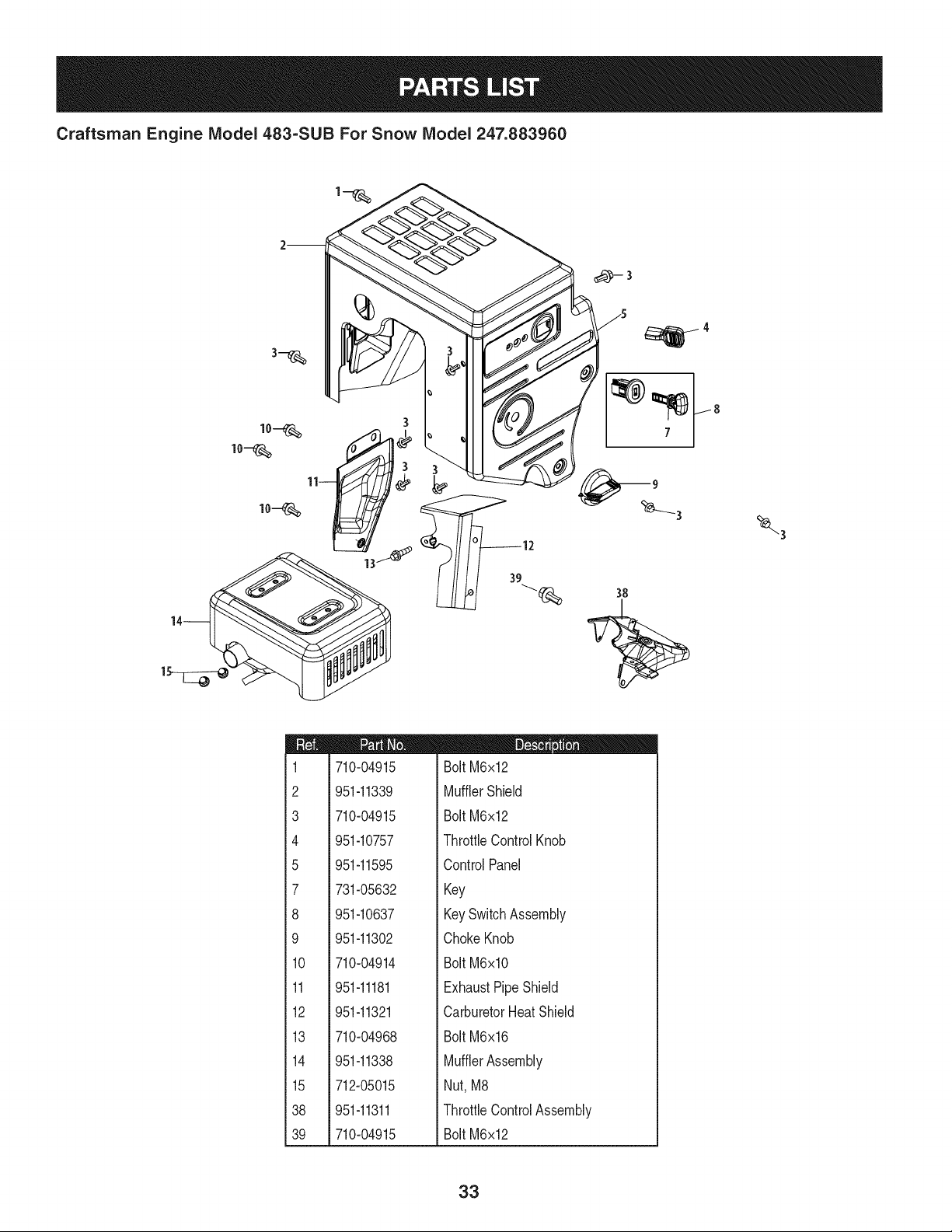
Craftsman Engine Model 483=SUB For Snow Model 247.883960
m
1
2
3
4
5
7
8
9
10
11
12
13
14
15
38
39
710-04915
951-11339
710-04915
951-10757
951-11595
731-05632
951-10637
951-11302
710-04914
951-11181
951-11321
710-04968
951-11338
712-05015
951-11311
710-04915
D = I! II
Bolt M6x12
MufflerShield
Bolt M6x12
ThrottleControlKnob
ControlPanel
Key
KeySwitchAssembly
ChokeKnob
Bolt M6xlO
ExhaustPipeShield
CarburetorHeatShield
Bolt M6x16
MufflerAssembly
Nut, M8
ThrottleControlAssembly
Bolt M6x12
33
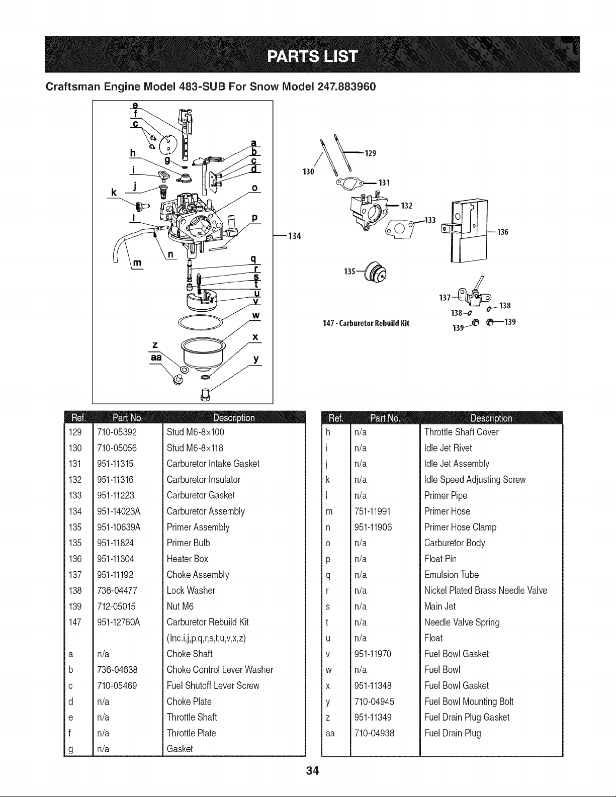
Craftsman Engine Model 483-SUB For Snow Model 247.883960
m
129
130
131
132
133
134
135
135
136
137
138
139
147
a
b
C
d
e
f
g
h
i
I
a
o
m
x
--134
710-05392
710-05056
951-11315
951-11316
951-11223
951-14023A
951-10639A
951-11824
951-11304
951-11192
736-04477
712-05015
951-12760A
n/a
736-04638
710-05469
n/a
n/a
n/a
n/a
StudM6-8x100
StudM6-8x118
CarburetorIntakeGasket
CarburetorInsulator
CarburetorGasket
CarburetorAssembly
PrimerAssembly
PrimerBulb
HeaterBox
ChokeAssembly
LockWasher
NutM6
CarburetorRebuildKit
(Inc.i,j,p,q,r,s,t,u,v,x,z)
ChokeShaft
ChokeControlLeverWasher
FuelShutoffLeverScrew
ChokePlate
ThrottleShaft
ThrottlePlate
Gasket
m
h
I
J
k
I
m
n
0
P
q
r
s
t
U
V
W
X
Y
Z
aa
n/a
n/a
n/a
n/a
n/a
751-11991
951-11906
n/a
n/a
n/a
n/a
n/a
n/a
n/a
951-11970
n/a
951-11348
710-04945
951-11349
710-04938
D = O e
ThrottleShaftCover
IdleJetRivet
IdleJetAssembly
IdleSpeedAdjustingScrew
PrimerPipe
PrimerHose
PrimerHoseClamp
CarburetorBody
FloatPin
EmulsionTube
NickelPlatedBrassNeedleValve
MainJet
NeedleValveSpring
Float
FuelBowlGasket
FuelBowl
FuelBowlGasket
FuelBowlMountingBolt
FuelDrainPlugGasket
FuelDrainPlug
34
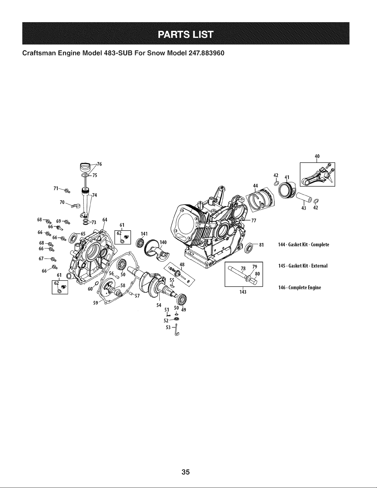
Craftsman Engine IViodel 483-SUB For Snow IViodel 247.883960
61
141
140
44
42
4O
I
43 42
144- GasketKit-Complete
145-GasketKit-External
146-CompleteEngine
49
35
Craftsman Engine IViodel 483=SUB For Snow IViodel 247.883960
m
4O
41
42
43
44
48
49
5O
51
52
53
54
55
56
57
58
59
60
61
62
64
65
66
67
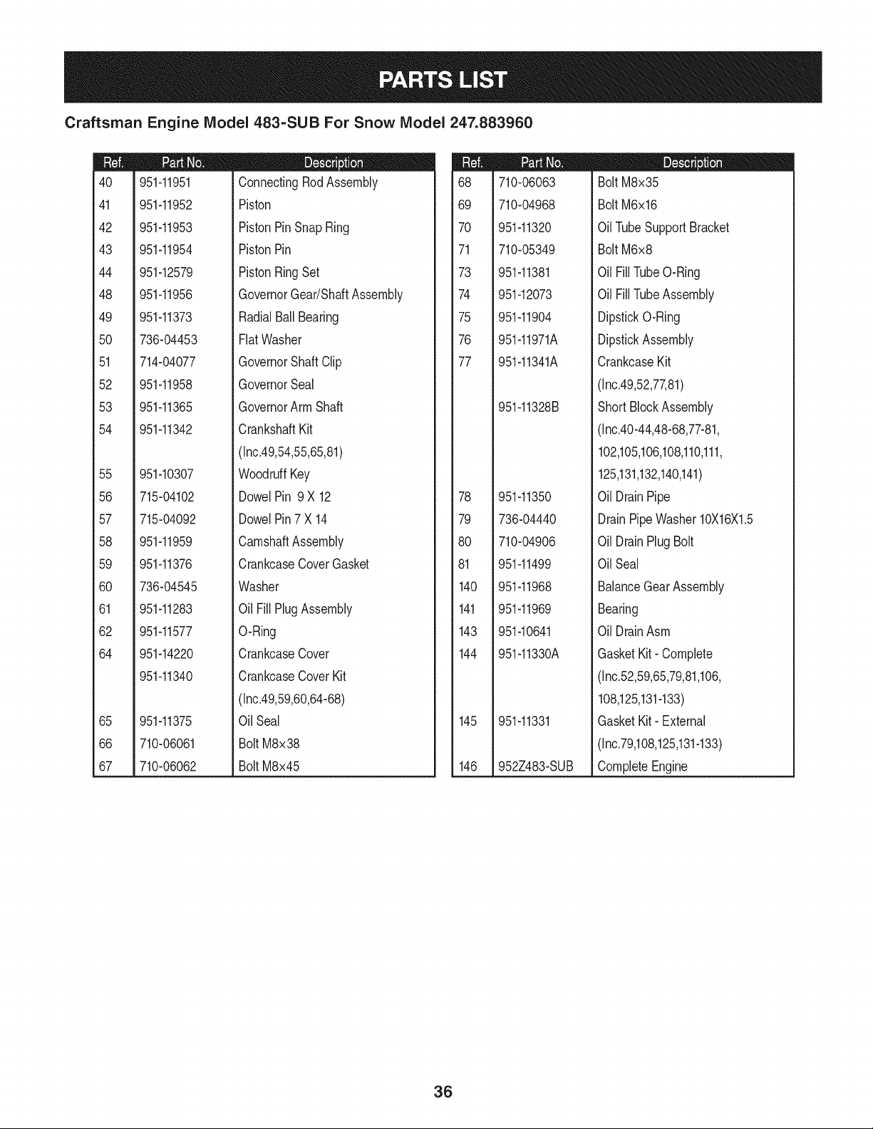
951-11951
951-11952
951-11953
951-11954
951-12579
951-11956
951-11373
736-04453
714-04077
951-11958
951-11365
951-11342
951-10307
715-04102
715-04092
951-11959
951-11376
736-04545
951-11283
951-11577
951-14220
951-11340
951-11375
710-06061
710-06062
m = O Q
ConnectingRodAssembly
Piston
PistonPinSnap Ring
PistonPin
PistonRingSet
GovernorGear/ShaftAssembly
RadialBallBearing
FlatWasher
GovernorShaftClip
GovernorSeal
GovernorArm Shaft
CrankshaftKit
(Inc.49,54,55,65,81)
WoodruffKey
DowelPin 9 X 12
DowelPin7 X 14
CamshaftAssembly
CrankcaseCoverGasket
Washer
Oil FillPlugAssembly
O-Ring
CrankcaseCover
CrankcaseCoverKit
(Inc.49,59,60,64-68)
Oil Seal
Bolt M8x38
Bolt M8x45
m
68
69
7O
71
73
74
75
76
77
78
79
8O
81
140
141
143
144
145
146
710-06063
710-04968
951-11320
710-05349
951-11381
951-12073
951-11904
951-11971A
951-11341A
951-11328B
951-11350
736-04440
710-04906
951-11499
951-11968
951-11969
951-10641
951-11330A
951-11331
952Z483-SUB
D = W O
Bolt M8x35
Bolt M6x16
OilTubeSupportBracket
Bolt M6x8
Oil FillTubeO-Ring
Oil FillTubeAssembly
DipstickO-Ring
DipstickAssembly
CrankcaseKit
(Inc.49,52,77,81)
ShortBlockAssembly
(Inc.40-44,48-68,77-81,
102,105,106,108,110,111,
125,131,132,140,141)
Oil DrainPipe
DrainPipeWasher10X16X1.5
Oil DrainPlugBolt
OilSeal
BalanceGearAssembly
Bearing
Oil DrainAsm
GasketKit- Complete
(Inc.52,59,65,79,81,106,
108,125,131-133)
GasketKit- External
(Inc.79,108,125,131-133)
CompleteEngine
36
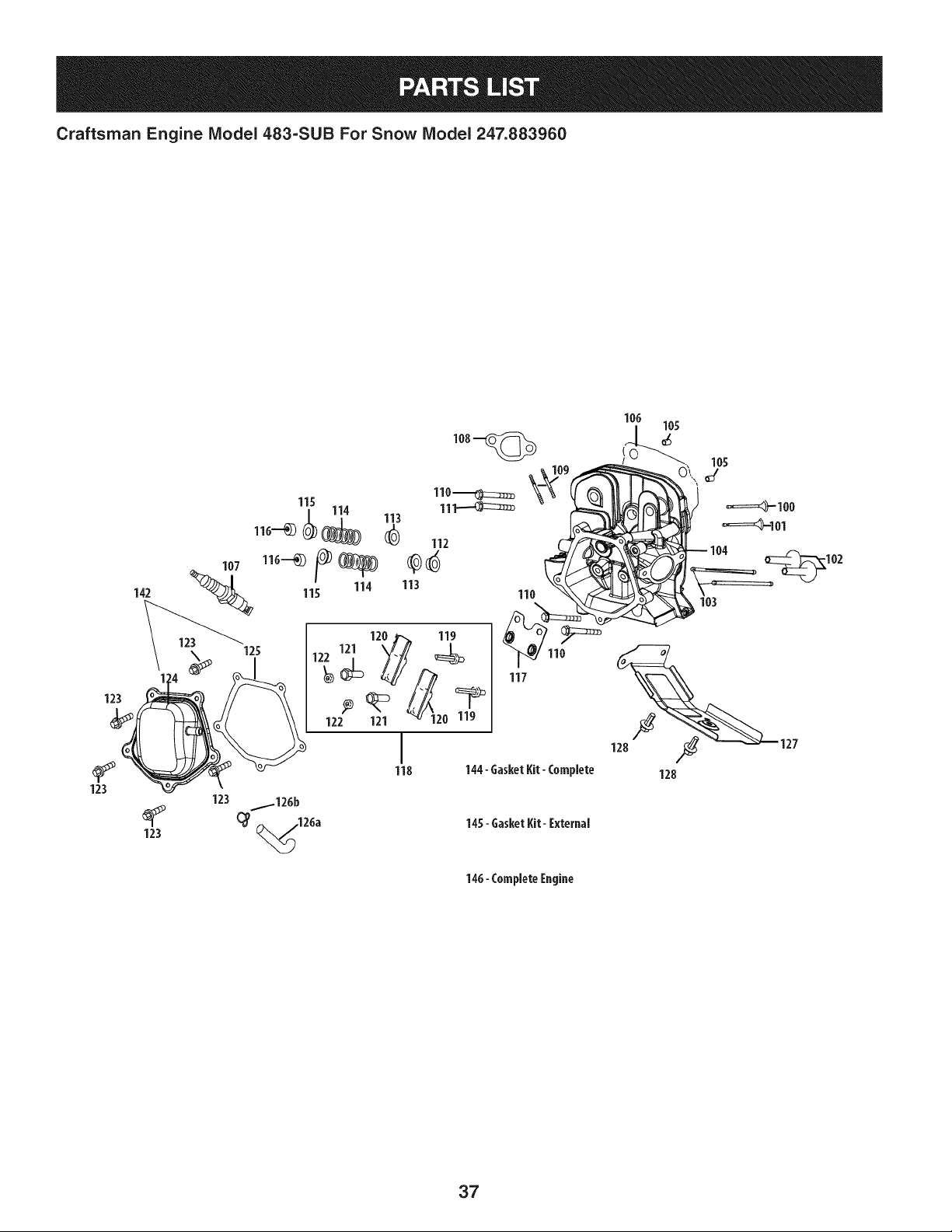
Craftsman Engine Model 483=SUB For Snow Model 247.883960
142
123
123
123
145- GasketKit- I:xternal
146- Complete[ngine
123
37
Craftsman Engine IViodel 483-SUB For Snow IViodel 247.883960
m
1CO
101
102
103
104
105
106
107
108
109
109
110
111
112
113
114
115
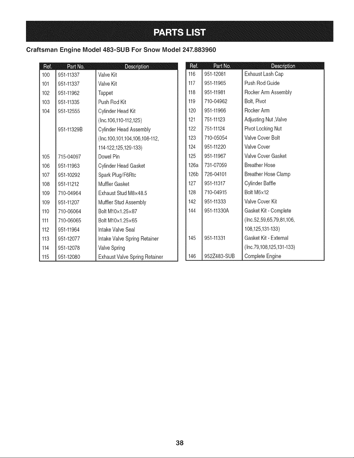
951-11337
951-11337
951-11962
951-11335
951-12555
951-11329B
715-04097
951-11963
951-10292
951-11212
710-04964
951-11207
710-06064
710-06065
951-11964
951-12077
951-12078
951-12080
D = O 0
ValveKit
ValveKit
Tappet
PushRodKit
CylinderHeadKit
(Inc.106,110-112,125)
CylinderHeadAssembly
(Inc.100,101,104,106,108-112,
114-122,125,129-133)
DowelPin
CylinderHeadGasket
SparkPlug/F6Rtc
MufflerGasket
ExhaustStudM8x48.5
MufflerStudAssembly
BoltM10x1.25x87
BoltM10x1.25x65
IntakeValveSeal
IntakeValveSpringRetainer
ValveSpring
ExhaustValveSpringRetainer
m
116
117
118
119
120
121
122
123
124
125
126a
126b
127
128
142
144
145
146
951-12081
951-11965
951-11981
710-04962
951-11966
751-11123
751-11124
710-05054
951-11220
951-11967
731-07059
726-04101
951-11317
710-04915
951-11333
951-11330A
951-11331
952Z483-SUB
D = O O
ExhaustLashCap
PushRodGuide
RockerArmAssembly
Bolt,Pivot
RockerArm
AdjustingNut,Valve
PivotLockingNut
ValveCoverBolt
ValveCover
ValveCoverGasket
BreatherHose
BreatherHoseClamp
CylinderBaffle
BoltM6x12
ValveCoverKit
GasketKit- Complete
(Inc.52,59,65,79,81,106,
108,125,131-133)
GasketKit- External
(Inc.79,108,125,131-133)
CompleteEngine
38
Craftsman Engine Model 483-SUB For Snow Model 247.883960
82
84
85
88
85
87
89
91
98
97
m
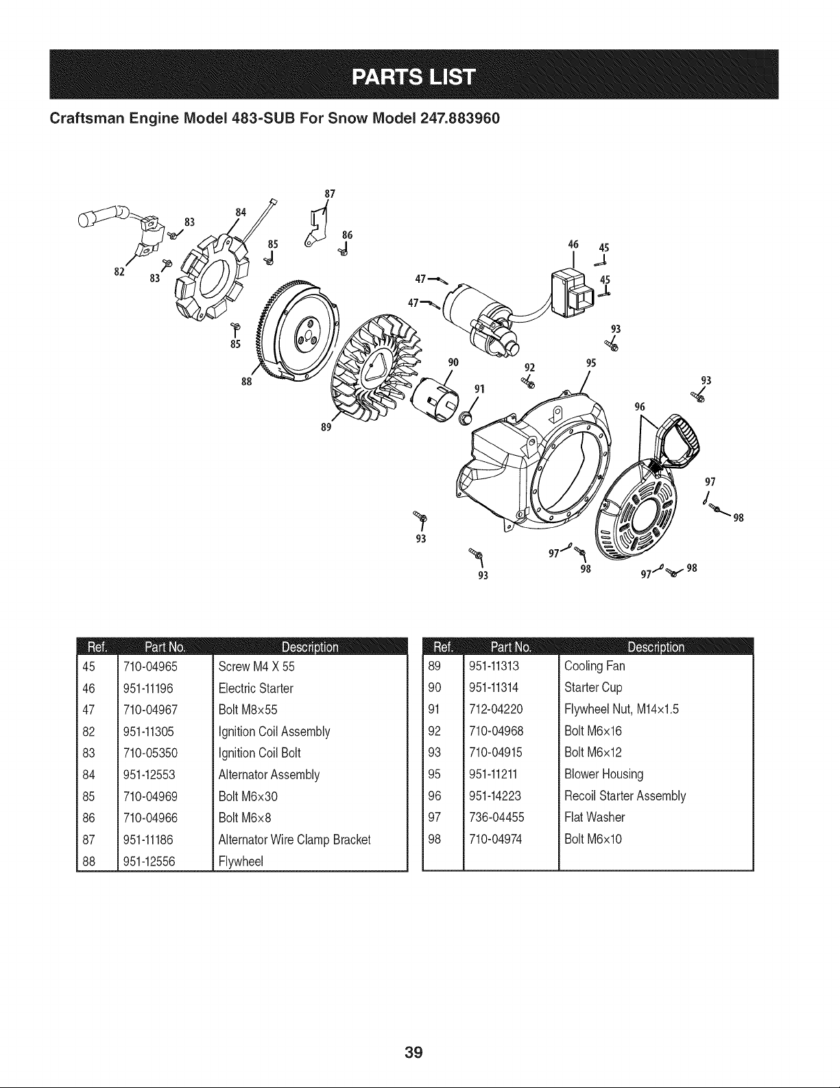
45
46
47
82
83
84
85
86
87
88
710-04965
951-11196
710-04967
951-11305
710-05350
951-12553
710-04969
710-04966
951-11186
951-12556
D = O
ScrewM4X55
ElectricStarter
Bolt M8x55
IgnitionCoilAssembly
IgnitionCoil Bolt
AlternatorAssembly
Bolt M6x30
Bolt M6x8
AlternatorWireClampBracket
Flywheel
m
89
90
91
92
93
95
96
97
98
951-11313
951-11314
712-04220
710-04968
710-04915
951-11211
951-14223
736-04455
710-04974
D = O
CoolingFan
StarterCup
FlywheelNut, M14x1.5
Bolt M6x16
Bolt M6x12
BlowerHousing
RecoilStarterAssembly
FlatWasher
Bolt M6xlO
39
Craftsman Engine IViodel 483=SUB For Snow IViodel 247.883960
m
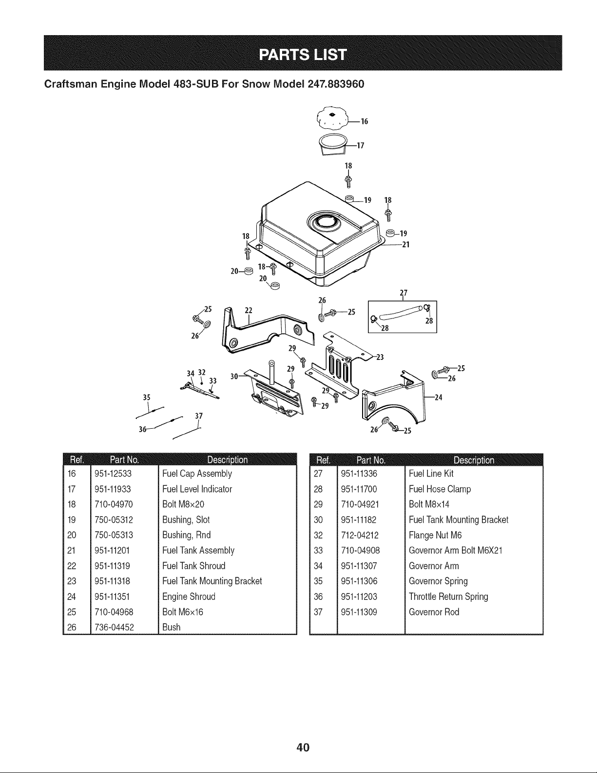
16
17
18
19
2O
21
22
23
24
25
26
/.-25
%
26/
27
I
:}4 32
951-12533
951-11933
710-04970
750-05312
750-05313
951-11201
951-11319
951-11318
951-11351
710-04968
736-04452
D = O
FuelCap Assembly
FuelLevelIndicator
BoltM8x20
Bushing,Slot
Bushing,Rnd
FuelTankAssembly
FuelTankShroud
FuelTankMountingBracket
EngineShroud
BoltM6x16
Bush
m
27
28
29
30
32
33
34
35
36
37
951-11336
951-11700
710-04921
951-11182
712-04212
710-04908
951-11307
951-11306
951-11203
951-11309
m = O O
FuelLineKit
FuelHoseClamp
Bolt M8x14
FuelTankMountingBracket
FlangeNutM6
GovernorArm Bolt M6X21
GovernorArm
GovernorSpring
ThrottleReturnSpring
GovernorRod
4O
Craftsman Snow Thrower IViodel 247.883960
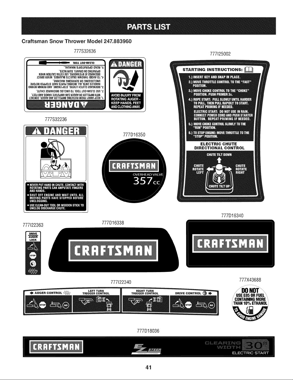
777S32636
1001 IIIO-NV]10
"IVI1NVIA]S,EIO/VEI3dOQV]EI"_
"S3OV:IEInS13AVEI9NO9NILVEI]d0
N3H_NOIlnV3VULX33sn'SEI3ONVIS,_9lV39EIVHOSI(]
103EIIOU3A3N'S31EIAPNI$103r80 NMOEIItlQIOAVO1"1_
'3NIHOVW9NIOIAEI3SEIO9NIOgO13NI1
3EIOd38O3ddOJ.S3AVHSIUVd9NIAOW]IV lllNn $31QNVH
ONIH38NIVW3EIONV'3FIION3d01S'SU3A31FI01111039VgN3SIO"_
"31fill0:I_EIVHOSIO901ONAO/1001 .LAO-NV3133Sn"_
"133:10NVSONVFI3].V±Ad_VNV0EI38AVEIOEI3il3dl_lH±IM
13VJ.NO0"EI38flVONVEI31"13dl_l9NIJ.VIOEIWOEI:I,WNWd3:Dt"L
777S32236
777D16350
777125002
ELECTRIC CHUTE
DIRECTIONAL CONTROL
777122363
777D16338
777D16340
777122340
777D18036
777X43688
/ •
;" USEE85ORFUEL'
CONTAININGMORE
THAN10% ETHANOL
41
MTD CONSUMER GROUP INC (MTD), the California Air Resources Board (CARB)
and the United States Environment Protection Agency (U. S. EPA)
Emission Control System Warranty Statement
(Owner's Defect Warranty Rights and Obligations)
EMISSIONCONTROLSYSTEMCOVERAGEIS APPLICABLETOCERTIFIEDENGINESPURCHASEDIN CALIFORNIAIN 2005 ANDTHERE-
AFTER,WHICHARE USEDINCALIFORNIA,ANDTO CERTIFIEDMODELYEAR2005AND LATERENGINESWHICHARE PURCHASEDAND
USEDELSEWHEREIN THE UNITEDSTATES.
Californiaandelsewherein the UnitedStatesEmissionControlDefectsWarrantyCoverage
The CaliforniaAir ResourcesBoard(CARB),U.S. EPAandMTDarepleasedto explaintheemissionscontrolsystemwarrantyonyour modelyear
2006and latersmalloff-roadengine.In California,new smalloff-roadenginesmustbe designed,builtand equippedto meet theStatesanti-smog
standards.Elsewhereinthe UnitedStates,newnon-road,spark-ignitionenginescertifiedfor model2005and later,mustmeet similarstandardsset
forthby the U.S. EPA.MTDmustwarrantythe emissioncontrolsystemonyourenginefor the periodof timelistedbelow,providedtherehasbeen
noabuse,neglector impropermaintenanceof your smalloff-roadengine.
Youremissioncontrolsystemmayincludepartssuch as the carburetor,fuel-injectionsystem,the ignitionsystem,and catalyticconverter,fueltanks,
fuel lines,fuel caps,valves,canisters,filters,vaporhoses,clamps,connectors,and otherassociatedemission-relatedcomponents.
Wherea warrantableconditionexists,MTDwill repairyoursmalloff-roadengineat nocost to yourincludingdiagnosis,partsand labor.
MANUFACTURER'S WARRANTY COVERAGE:
Thisemissionscontrolsystemis warrantedfor twoyears.If anyemission-relatedpart onyourengineis defective,the part will be repairedor
replacedby MTD.
OWNER'S WARRANTY RESPONSIBILITIES:
As the smalloff-roadengineowner,youare responsibleforthe performanceof the requiredmaintenancelisted in your Owner'sManual.MTD
recommendsthatyou retainall yourreceiptscoveringmaintenanceson yoursmalloff-roadengine,but MTDcan not denywarrantysolelyfor the
lackof receiptsor foryour failureto ensurethe performanceto all scheduledmaintenance.
As the smalloff-roadengineowner,youshouldhoweverbe awarethat MTDmaydenyyour warrantycoverageif yoursmalloff-roadengineor part
hasfaileddue toabuse, neglect,impropermaintenanceor unapprovedmodifications.
Youare responsiblefor presentingyour smalloff-roadengineto an AuthorizedMTDServiceDealeras soonas a problemexists.Thewarranted
repairsshouldbe completedin a reasonableamountof time,notto exceed30 days.
Ifyou haveanyquestionsregardingyourwarrantyrightsand responsibilities,you shouldcontacta MTDServiceRepresentativeat 1-800-800-7310
andaddressis MTDCONSUMERGROUP,RO.Box361131,ClevelandOH,44136-0019.
DEFECTS WARRANTY REQUIREMENTS FOR 1995 AND LATER SMALL OFF-ROAD ENGINES:
Thissectionappliesto 1995and later smalloff-roadengines.The warrantyperiodbeginson the datethe engineor equipmentis deliveredto an
ultimatepurchaser.
(a) GeneralEmissionsWarrantyCoverage_
MTDmustwarrantto the ultimatepurchaserandeachsubsequentpurchaserthat the engineis:
(1)Designed,built,andequippedsoas to conformwith all applicableregulationsadoptedby the Air ResourcesBoardpursuantto its authorityin
Chapters1and 2,Part 5, Division26 of the Healthand SafetyCode; and
(2) Freefromdefectsin materialsandworkmanshipthat causethe failureof a warrantedpart to be identicalin all materialrespectsto the partas
describedin theenginemanufacturer'sapplicationfor certificationfora periodof twoyears.
.(b)The warrantyon emissions-relatedpartswill be interpretedas follows:
(1)Anywarrantedpart thatis not scheduledfor replacementas requiredmaintenanceinthe writteninstructionsrequiredby Subsection(c)
mustbewarrantedfor the warrantyperioddefinedinSubsection(a)(2). If any such partfails duringthe periodof warrantycoverage,it mustbe
repairedor replacedby MTDaccordingto Subsection(4) below.Anysuch part repairedor replacedunder thewarrantymustbe warrantedfor
the remainingwarrantyperiod.
(2)Any warrantedpartthat is scheduledonlyfor regularinspectioninthe writteninstructionsrequiredby Subsection(c) must bewarrantedfor
thewarrantyperioddefinedin Subsection(a)(2).A statementin such writteninstructionsto the effectof "repairor replaceas necessary"will
not reducethe periodof warrantycoverage.Anysuchpart repairedor replacedunderwarrantymustbe warrantedforthe remainingwarranty
period.
(3) Anywarrantedpartthat whichis scheduledfor replacementas requiredmaintenancein the writteninstructionsrequiredby Subsection(c)
mustbewarrantedfor the periodof timepriorto the first scheduledreplacementpointforthat part. If the part fails priorto thefirst scheduled
replacement,the part mustbe repairedor replacedby MTDaccordingto Subsection(4) below.Any suchpart repairedor replacedunder
warrantymustbewarrantedfor the remainderof the period priorto the first scheduledreplacementpointfor the part.
(4) Repairor replacementof any warrantedpartunder thewarrantyprovisionsof thisarticle mustbe performedat no chargeto the ownerat a
warrantystation.
(5) Notwithstandingthe provisionsof Subsection(4)above,warrantyservicesor repairsmustbe providedat all MTDdistributioncentersthat
arefranchisedto servicethe subjectengines.
(6)Theownermustnotbechargedfordiagnosticlaborthatleadstothedeterminationthatawarrantedpartisinfactdefective,providedthat
suchdiagnosticworkisperformedatawarrantystation.
(7)Theenginemanufacturerisliablefordamagestootherenginecomponentsproximatelycausedbyafailureunderwarrantyofanywarranted
part.
(8)Throughouttheengine'swarrantyperioddefinedinSubsection(a)(2),MTDwillmaintaina supplyofwarrantedpartssufficienttomeetthe
expecteddemandforsuchparts.
(9)Anyreplacementpartmaybeusedintheperformanceofanywarrantymaintenanceorrepairsandmustbeprovidedwithoutchargetothe
owner.SuchusewillnotreducethewarrantyobligationsofMTD.
(10)Add-onormodifiedpartsthatarenotexemptedbytheAirResourcesBoardmaynotbeused.Theuseofanynon-exemptedadd-onor
modifiedpartsshallbegroundsfordisallowingawarrantyclaimmadeinaccordancewiththisarticle.Theenginemanufacturershallnotbe
liableunderthisarticletowarrantfailuresofwarrantedpartscausedbytheuseofnon-exemptedadd-onormodifiedpart.
(c) MTDwill includea copyof the followingemissionwarrantypartslistwitheach newengine,usingthoseportionsof the listapplicableto the
e__&gine.
(1)FuelMeteringSystem
• Coldstart enrichmentsystem(soft choke)
,,Carburetorandinternalparts
• Fuel Pump
• FuelTank
(2)Air InductionSystem
• Air cleaner
• Intakemanifold
(3) IgnitionSystem
• Sparkplug(s)
• MagnetoIgnitionSystem
(4)ExhaustSystem
Catalyticconverter
• SAI (Reedvalve)
(5) MiscellaneousItemsUsedin AboveSystem
Vacuum,temperature, position,time sensitivevalvesand switches
Connectorsandassemblies
(6) Evaporativecontrol
• Fuel Hosecertifiedfor ARBevaporativeemissionof 2006.
• Fuel HoseClamps
Tetheredfuel cap
Carboncanister
• Vaporlines
GD0C-100174Rev.B
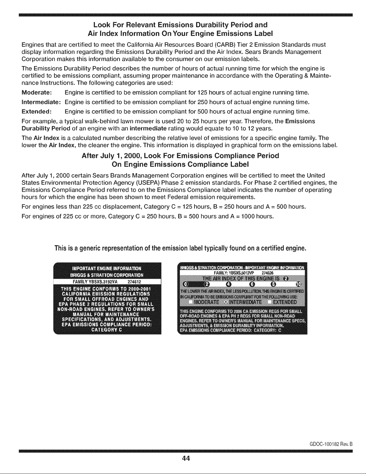
Look For Relevant Emissions Durability Period and
Air index information On Your Engine Emissions Label
Engines that are certified to meet the California Air Resources Board (CARB) Tier 2 Emission Standards must
display information regarding the Emissions Durability Period and the Air Index. Sears Brands Management
Corporation makes this information available to the consumer on our emission labels.
The Emissions Durability Period describes the number of hours of actual running time for which the engine is
certified to be emissions compliant, assuming proper maintenance in accordance with the Operating & Mainte-
nance Instructions. The following categories are used:
Moderate: Engine is certified to be emission compliant for 125 hours of actual engine running time.
Intermediate: Engine is certified to be emission compliant for 250 hours of actual engine running time.
Extended: Engine is certified to be emission compliant for 500 hours of actual engine running time.
For example, a typical walk-behind lawn mower is used 20 to 25 hours per year. Therefore, the Emissions
Durability Period of an engine with an intermediate rating would equate to 10 to 12 years.
The Air index is a calculated number describing the relative level of emissions for a specific engine family. The
lower the Air Index, the cleaner the engine. This information is displayed in graphical form on the emissions label.
After July 1,2000, Look For Emissions Compliance Period
On Engine Emissions Compliance Label
After July 1, 2000 certain Sears Brands Management Corporation engines will be certified to meet the United
States Environmental Protection Agency (USEPA) Phase 2 emission standards. For Phase 2 certified engines, the
Emissions Compliance Period referred to on the Emissions Compliance label indicates the number of operating
hours for which the engine has been shown to meet Federal emission requirements.
For engines less than 225 cc displacement, Category C = 125 hours, B = 250 hours and A = 500 hours.
For engines of 225 cc or more, Category C = 250 hours, B = 500 hours and A = 1000 hours.
This is a generic representation of the emission label typically found on a certified engine.
FAMILYYBSXS.3192VA 274812
GDOC-100182Rev.B
44
Congratulations on making a smart purchase. Your new Craftsman® product is designed and
manufactured for years of dependable operation. But like all products, it may require repair
from time to time. That's when having a Repair Protection Agreement can save you money and
aggravation.
Here's what the Repair Protection Agreement* includes:
[] Expert service by our 10,000 professional repair specialists
[] Unlimited service and no charge for parts and labor on all covered repairs
[] Product replacement up to $1500 if your covered product can't be fixed
[] Discount of 25% from regular price of service and related installed parts not covered by the
agreement; also, 25% off regular price of preventive maintenance check
[] Fast help by phone - we call it Rapid Resolution - phone support from a Sears representative.
Think of us as a "talking owner's manual."
Once you purchase the Repair Protection Agreement, a simple phone call is all that it takes for you
to schedule service. You can call anytime day or night, or schedule a service appointment online.
The Repair Protection Agreement is a risk-free purchase. If you cancel for any reason during the
product warranty period, we will provide a full refund. Or, a prorated refund anytime after the
product warranty period expires. Purchase your Repair Protection Agreement today!
Some limitations and exclusions apply. For prices and additional information in the U.S.A.
call 1=800=827=6655.
*Coverage in Canada varies on some items. For full details call Sears Canada at 1=800=361=
6665.
Sears Installation Service
For Sears professional installation of home appliances, garage door openers, water heaters, and
other major home items, in the U.S.A. or Canada call 1=800=4=MY=HOME®.
45
Declaraci6n de garantia ............................ Pagina 46
Practicas operaci6n seguras ..................... Pagina 47
Montaje ...................................................... Pagina 51
Operaci6n .................................................. Pagina 57
Servicio y Mantenimiento .......................... Pagina 62
Almacenamiento fuera de temporada ....... Pagina 69
Soluci6n de problemas .............................. Pagina 70
Acuerdo de protecci6n para reparaciones .... Pagina 75
Lista de piezas ........................................... Pagina 26
NOmero de servicio ................................... Cubierta
posterior
GARANTJA COMPLETA CRAFTSMAN POR DOS ANOS
PORDOSANOSapartir dela fechade la cornpra,este productoest_ garantizadopor defectosen los rnaterialesy la rnanode obra.
Los productosdefectuososser&nreparadossin costoo reemplazadossin costosi la reparaci6nno est&disponible.
GARANTJA DE POR VlDA LIMITADA ADIClONAL en la tolva de UPPER y LOWER
PARASIEMPREY CUANDOSE UTILIZApor el propietariooriginaldespu6sdelsegundoaSodesdela fecha de compra,el conductosuperiore
inferiorde estequitanievesest_n garantizadoscontracualquierdefectode rnaterialeso rnanode obradebeserverificadoporun proveedorde
servicioautorizadoSears.Con elcornprobantede cornpra,usted recibir_una rarnpanuevade forrnagratuita.Ustedes responsablepor el costo
de larnanode obra de instalaci6ny otrosgastosocasionadosparaverificareldefecto.
Paraobtener inforrnaci6nsobreel alcancede la garantiay solicitarla reparaci6no el reernplazo,visiteel sitioWeb: www.craftsrnan.corn
Esta garantiacubre0NICAMENTElos defectos en los materiales yen la rnano de obra. Esta garantiaNOcubre:
• Elernentosno renovablesquepuedendesgastarsepor el uso normal,duranteel plazode la garantia,incluyendoentreotros,las barrenas,
las paletasdelas barrenas,los cortadoresde desplazarniento,laszapatasantideslizantes,la placade raspado,lospasadoresdecuchilla,
la bujia,elfiltro de aire,las correasy el filtrodeaceite.
• Serviciosde rnantenirnientoestandar,carnbiosde aceiteo afinaci6n.
• Carnbiode neurnAticoso reparacionespor pinchadurascon objetosexternoscornoclavos,espinas,toconeso vidrios.
• Reernplazoo reparaci6nde neurn_ticoso ruedascornoresultadodel desgastenormal,un accidente,o funcionarniento
o rnantenirnientoincorrectos.
• Reparacionesrequeridascornoresultadodel uso inadecuadopor partedel operador,incluyendoentreotrosel da_oocasionadopor objetos
queirnpactanla rnaquinay quetuercenel bastidor,el eje de la barrena,etc., o debido a que el motorfueaceleradoen exceso.
• Reparacionesnecesariasdebidoa negligenciadeloperador,incluyendoentre otros,da_osrnec_nicoy el6ctricoocasionadopor
unalmacenarnientonoapropiado,fallaporel uso deaceitede gradoy/o cantidadnoapropiadoso falla por no dar rnantenirniento
alequipode acuerdocon las instruccionescontenidasenel manualdel operador.
• Lirnpiezao reparacionesdel motor(sistemade combustible)debidasa combustibleque se deterrninaestAcontarninadou oxidado(viejo).
Engeneral,el combustibledebe utilizarseen un periodono mayorde 30 dias a partirde su adquisici6n.
• Eldeterioroy desgastenormalde losacabadosexteriores,o reernplazode laetiquetadelproducto.
Lapresentegaranfiase anula si se utilizaeste productoalgunavez para prestarservicioscornercialeso si se Ioalquilaa otra persona.
Estagaranfialeotorgaderechoslegalesespecificos,pero ustedpodria gozarde otros derechosen raz6nde su lugarde residencia.
Sears Brands Management Corporation, Hoffman Estates, IL 60179
Tipode aceitedelmotor:
Capacidaddeaceitedel motor:
Capacidaddecombustible:
Bujfas:
Separaci6nde lasbujias:
SAE 5W-30
37 onzas
Aprox. 5 cuartos
F6RTC (951-10292)
.020" a .030"
N_merode modelo ..........................................................
N_merode serie ..............................................................
Fechade compra .............................................................
Registrearriba el nOrnerodel rnodelo,el nOrnerode seriey la fecha
decornpra
© Sears Brands,LLC
46
Lapresenciade este sfrnboloindicaque setrata de instrucciones
irnportantesde seguridadquese deben respetarpara evitar
poneren peligrosu seguridadpersonaly/o materialy la de otras
personas.Leay siga todaslas instruccionesde este manualantes
de poneren funcionarnientoestarn_.quina.Si no respetaestas
instruccionespodrfaprovocarlesionespersonales.Cuandoveaeste
sfrnbolo,ipresteatenci6na la advertencia!
PROPOSICION 65 DE CALIFORNIA
Elescapedel motorde este producto,algunosde suscornponentes
y algunoscornponentesdel vehfculocontieneno liberansustancias
qufrnicasqueel estado de Californiaconsideraque puedenproducir
c_.ncer,defectosde nacirnientou otros problernasreproductivos.
Estarn_.quinarueconstruidaparaseroperadadeacuerdocon
las reglasde seguridadcontenidasen este manual.AI igualque
concualquiertipo deequipo rnotorizado,undescuidoo error por
partedeloperadorpuedeproducirlesionesgraves.Esta rn_.quina
es capazde arnputarrnanosy piesy de arrojarobjetoscon gran
fuerza.Deno respetarlas instruccionesde seguridadsiguientesse
puedenproducirlesionesgraveso la rnuerte.
Su responsabilidad--Restrinja el usode esta rn_.quina
rnotorizadaalas personasque lean,cornprendany respetenlas
advertenciase instruccionesqueaparecenen estemanualyen la
rn_.quina.
iGUARDEESTASINSTRUCCIONES!
CAPACITACI6N
• Lea,entienday curnplatodaslas instruccionesincluidasen
la rn_.quinay en los rnanualesantesde rnontarlay utiNzarla.
Guardeestemanualen un lugarseguroparaconsultasfuturasy
peri6dicas,asf cornopara solicitarrepuestos.
• Leael Manualdel Operadory sigatodas las advertenciase
instruccionesde seguridad.Elfracasode hacerasf puedecausar
la heridaseriaal operadory/o personaspresentes.
• Farniliarfcesecontodoslos controlesy con el usoadecuado
delos rnisrnos.Sepa c6rnodetenerla rn_.quinay desactivarlos
controlesr_.pidarnente.
• No perrnitanuncaque los ni_osrnenoresde 14a_osutilicen
estarn_.quina.Los ni_osde 14a_osen adelantedebenleer y
entenderlas instruccionesde operaci6ny norrnasdeseguridad
contenidasen este manual,yen la rn_.quinaydebenser entrena-
dosy supervisadosporun adulto.
• Nuncaperrnitaquelos adultosoperenesta rn_.quinasin recibir
antesla instrucci6napropiada.
• Losobjetosarrojadosporla rn_.quinapuedenproducirlesiones
graves.Planifiqueel patr6nen el que va air arrojandonievepara
evitarque la descargade materialse realicehacialos carninos,
los observadores,etc.
• Mantengaa losobservadores,ayudantes,rnascotasy ni_ospor
Io rnenosa 75piesde la rn_.quinarnientrasla rnisrnaest,.en
funcionarniento.Detengala rn_.quinasi alguienseacerca.
• Seaprecavidopara evitarpatinarseo caerseespecialrnente
cuandooperala rn_.quinaen reversa.
PR E PARATIVO S
Inspeccionerninuciosarnenteel _.readondeutilizar_,el equipo.Saque
todoslos felpudos,peri6dicos,trineos,tablas,cablesy otros objetos
extra_oscon los quepodrfatropezaro que podrfanser arrojadospor
labarrena/irnpulsor.
• Paraprotegerselosojos utilice siernpreanteojosoantiparras
de seguridadrnientrasoperala rn_.quinao rnientrasla ajusta
o repara.Losobjetosarrojadosquerebotanpuedenproducir
lesionesocularesgraves.
• Noopere la rn_.quinasin la vestirnentaadecuadaparaestaral
airelibreen invierno.No utilicealhajas,bufandaslargasu otras
prendassueltasquepodrfanenredarseen las partes rn6viles.
UtiNceun calzadoespecialparasuperficiesresbaladizas.
• Useun prolongadory un tornacorrientedetres cables con
conexi6na tierraparatodas las rn_.quinascon rnotoresde
encendidoel_ctrico.
• Ajustela alturade la caja del tornacorrienteparaNrnpiarla grava
o las superficiescon piedrastrituradas.
• Desengranetodaslas palancasde controlantesde arrancarel
motor.
• Nuncaintenterealizarajustesrnientrasel motorest,. en rnarcha
exceptoen los casosespecfficarnenterecornendadosen el
manualdeloperador.
• Dejeque el motor y la rn_.quinase adaptena la ternperatura
exteriorantesde cornenzara sacarla nieve.
4.7
Manejo seguro de la gasolina
Paraevitarlesionespersonales0 daSosrnaterialestengarnucho
cuidadocuandotrabajecon gasolina.Lagasolinaes surnarnente
inflarnabley sus vaporespuedencausarexplosiones.Si se derrarna
gasolinaencirna0 sobrela ropa se puedelesionargravernenteya que
se puedeincendiar. L&vesela piel y c&rnbiesede ropade inrnediato.
• Utilices610los recipientesparagasolinaautorizados.
• Apaguetodoslos cigarrillos,cigarros,pipasy otrasfuentesde
cornbusfi6n.
• Nuncacarguecombustibleen la rn&quinaen un espaciocerrado.
• Nuncasaquela tapadel combustibleni agreguecombustible
rnientrasel motorest&caliente0 en rnarcha.
• Dejequeel motorse enfriepor I0 rnenosdos rninutosantesde
volvera cargarcombustible.
• Nuncalleneen excesoel dep6sitode combustible.Lleneel
tanquea no rn&sde 1/2pulgadapordebajode la basedelcuello
de Ilenadodejandoespacioparaladilataci6ndeIcombustible.
• Vuelvaa colocarla tapade la gasoiinay aj_stelabien.
• Lirnpieel combustiblequese hayaderrarnadosobreel motory el
equipo.Trasladela rn&quinaa otra zona. Espere5 rninutosantes
deencenderel motor.
• Nuncaalrnacenela rn&quina0 el recipientede combustibleen
unespaciocerradodonde hayafuego,chispas0 luz piloto(por
ejernplo,hornos,calentadoresdeagua,calefactores,secadores
de ropa,etc.).
• Dejequela rn_.quinase enfrieporIo rnenos5 rninutosantesde
guardarla.
• NuncaIlenelos recipientesen el interiorde un vehiculoo carni6n
ocaja de rernolquecon recubrirnientospl_.sticos.Coloque
siernprelos recipientesen el pisoy lejosdel vehiculoantesde
Ilenarlos.
• Sies posible,retireel equipoa gasolinadel carni6no rernolque
y II_neloen el suelo.Siesto no es posible,Ileneel equipoen un
rernolquecon contenedorport_.til,envez de desdeuna boquilla
dispensadoradegasolina.
• Mantengala boquilladispensadoraen contactocon el hordedel
dep6sitode combustibleo con la aberturadel recipienteen todo
rnornento,hastaterrninarlacarga. No utiliceun dispositivode
apertura/cierrede boquilla.
FUNCIONANIIENTO
• No pongalas rnanoso los piescercadelas piezasrotatorias,
en lacajade la barrena/ irnpulsoro en el rnontajedelcanalde
descarga.Hacercontactocon piezasgiratoriaspuederesultaren
laarnputaci6ndernanoso pies.
• La palancadecontrolde la barrena/ irnpulsores un dispositivo
de seguridad.Nuncaevite su funcionarniento.De hacerlola
operaci6nde la rn_.quinaes riesgosay puedeocasionarlesiones.
• Las palancasdecontrol debenfuncionarbien en arnbasdirec-
cionesy regresarautorn_.ticarnentea la posici6nde desengrane
cuandose lassuelta.
• Nuncaoperela rn_.quinasi faltaunrnontajedelcanalo si el
rnisrnoest,.daSado.Mantengatodos losdispositivosde seguri-
daden su lugaryen funcionarniento.
• Nuncaenciendael motor en espacioscerradoso en una zona
con pocaventilaci6n.Elescapedel motorcontienernon6xidode
carbono,ungas inodoroy letal.
• Noutilice la rn_.quinabajola influenciadelalcoholo las drogas.
• El silenciadory el motorse calientany puedencausarquernadu-
ras.Nolos toque.Mantengaa los niSosalejados.
• Seasurnarnenteprecavidocuandoopere la rn_.quinasobreuna
superficiecon gravaocuandola cruce.Mant_ngasealerta porsi
se presentanpeligrosocultoso tr_.nsito.
• Tengacuidadocuandocarnbiede direcci6no cuandoopere
la rn_.quinaen pendientes.Nouse la rn_.quinaen pendientes
pronunciadas.
• Planifiqueel patr6nen el que va air arrojandonieveparaevitar
que la descargade materialse produzcahacialas ventanas,
las paredes,losautorn6viles,etc.y evitarasi posiblesdaSos
rnaterialeso lesionesproducidaspor los rebotes.
• Nuncadirija la descargahacialos niSos,los observadoreso las
rnascotasni dejeque nadiese pare delantede la rn_.quina.
• Nosobrecarguela capacidadde la rn_.quinatratandode sacarla
nievernuyr_.pidarnente.
• Nuncaopereesta rn_.quinasin buenavisibilidado ilurninaci6n.
Siernpredebeestar segurode que est,. bien afirrnadoy su-
jetandofirrnernentelas rnanijas.Carnine,nuncacorra.
• Cortela corrientea la barrena/ irnpulsorcuandotransportela
rn_.quinao cuandola rnisrnano est,. en uso.
• Nuncaoperela rn_.quinaaalta velocidadde desplazarniento
sobresuperficiesresbaladizas.Mirehaciaabajoy haciaatr_.sy
tengacuidadocuandovayarnarchaatr_.s.
• Si la rn_.quinacornenzaraa vibrarde rnaneraanorrnal,detengael
motor,desconecteel cablede la bujia y p6ngalade rnaneraque
hagarnasacontra el motor.Inspeccionela rn_.quinarninuciosa-
rnenteparaver si est,.daSada.Reparetodos los daSosantesde
encendery operarla rn_.quina.
• Desengranetodas las palancasde controly detengael motor
antesde dejar la posici6nde operaci6n(detr_.sdelas rnanijas).
Espereaque la barrena/ irnpulsorse detengaporcornpleto
antesde destaparel rnontajedel canalo realizarajustese
inspecciones.
• Nuncapongalas rnanosen las aberturasde descargao de
recolecci6n.Utilicesiernprela herrarnientade lirnpiezaque se
adjuntaparadestaparla aberturade descarga.Nodestapeel
rnontajedelcanal rnientrasel motorest,. en funcionarniento.
Antesde destaparlo,apagueel motory perrnanezcadetr_.sde las
rnanijashastaque todaslas partes rn6vilesse hayandetenido.
• Uses61ounionesy accesoriosaprobadospot el fabricante(por
ejernplo,pesasparalas ruedas,cadenaspara los neurn_.ticos,
cabinas,etc.). Paraobtenerrn_.sinforrnaci6nacercade estos
ternas,Ilarneal 1-800-469-4663.
48
• Paraencenderel motor,jale de lacuerdalentarnentehastaque
sientaresistencia,luegojale r_.pidarnente.El replieguer_.pidode
la cuerdade arranque(tensi6nde retroceso)lejalar_,la rnanoy
el brazohaciael motorrn_.sr_.pidodeIo queustedpuedesoltar.
El resultadopuedenserhuesosrotos,fracturas,hernatornaso
esguinces.
• Si se presentansituacionesqueno est_.nprevistasen este
manual,seacuidadosoy use el sentidocornOn.
• Parapedirrepuestoso serviciohorarioparaeste producto,Ilarne
a 1-800-469-4663.
MANTENIMIENTO Y ALMACENAMIENTO
• Nuncaalterelos dispositivosde seguridad.Controleperi6dica-
rnentequefuncionencorrectarnente.Rernitasealas secciones
demantenirnientoy ajustede estemanual.
• Antesde realizarla lirnpieza,repararo revisarla rn_.quina,
desengranetodas laspalancasde controly detengael motor.
Esperea quela barrena/ irnpulsorse detengapor cornpleto.
Desconecteel cablede la bujfay p6ngalohaciendornasacontra
el motorparaevitarque se enciendaaccidentalrnente.
• Controlefrecuenternentequetodos lospernosy tornillosest_n
bienajustadosparacornprobarquela rn_.quinase encuentra
encondicionessegurasde funcionarniento.Adern_.s,hagauna
inspecci6nvisual de la rn_.quinaparaverificarsi est,.da_ada.
• No carnbielaconfiguraci6ndel reguladordel motorni acelere
dernasiadoel rnisrno.El reguladordel motorcontrolala velocidad
rn_.xirnaseguradefuncionarnientodel motor.
• Las placasde raspadoy las zapatasantideslizantesque se
usancon la rn_.quinaquitanievese desgastany se da_an.
Paraprotegersu seguridad,verifiquefrecuenternentetodoslos
cornponentesy reernpl_.celoss61ocon partesde los fabricantes
deequiposoriginales(OEM). iEI usode piezasque no curnplen
con lasespecificacionesdelequipooriginalpuederesultaren
rendirnientoinadecuadoadern_.sde poneren riesgola seguridad!
• Reviselas palancasde controlperi6dicarnenteparaverificar
queengraneny desengranenadecuadarnentey ajOstelossi es
necesario.Consultela secci6nde ajustesde este manualdel
operadorparaobtenerinstrucciones.
• Mantengao reernplacelasetiquetasde seguridade instrucciones
segQnseanecesario.
• Respetelas norrnasreferentesa la disposici6ncorrectay las
reglarnentacionessobregasolina,aceite,etc. para protegerel
medicarnbiente.
• Antesdealrnacenarla rn_.quinaenci_ndalaunosrninutospara
sacarla nievequehayaquedadoen la rnisrnay paraevitarasi
quese congelela barrena/irnpulsor.
• SegOnla Cornisi6nde Seguridadde Productosparael Consurni-
dorde los EstadosUnidos(CPSC)y laAgenciade Protecci6n
Arnbientalde los EstadosUnidos(EPA),este productotieneuna
vida Qtilmediadesiete(7)a_os,6 60 horasde funcionarniento.
AI finalizarlavida Otilmedia,adquieraunarn_.quinanuevao
hagainspeccionaranualrnente_stapor un distribuidorde servicio
autorizadoparacerciorarsede quetodoslos sisternasrnec_.nicos
y deseguridadfuncionancorrectarnentey no tienenexcesivo
desgaste.Si no Iohace, puedenproducirseaccidentes,lesiones
o rnuerte
• Nuncaalrnacenela rn_.quinao el recipientedecombustibleen un
espaciocerradodondehayafuego,chispaso luz pilotocornopor
ejernplo,calentadoresde agua,hornos,secadoresde ropa,etc.
• Consultesiernpreel manualdel operadorparaobtener
instruccionesadecuadaspara el alrnacenarnientofuerade
ternporadaVerifiquefrecuenternentelaIfneade combustible,el
tanque,el tap6n,y losaccesoriosbuscandorajaduraso perdidas.
Reernplacede ser necesario.
• Nod_ arranqueal motorsi no est,. la bujia de encendido.
NO MODIFIQUE EL MOTOR
Paraevitarlesionesgraveso la rnuerte,no rnodifiqueel motorbajo
ningunacircunstancia.Si carnbiala configuraci6ndel reguladorel
motorpuededescontrolarsey operara velocidadesinseguras.Nunca
carnbielaconfiguraci6ndef_.bricadel reguladordel motor.
AVISO REFERIDO A EMISIONES
Losrnotoresqueest&ncertificadosy curnplencon las regulaciones
de ernisionesfederalesEPAy de Californiapara SORE(Equipos
peque_ostodoterreno)est_.ncertificadosparaoperarcon gasolina
cornOnsinplornoy puedenincluirlossiguientessisternasde control
de ernisiones:Modificaci6nde motor(EM) y catalizadorde tres vias
(TWO)si est_.nequipadosde esa rnanera.
GUARDACHISPAS
Estarn&quinaest,. equipadacon un motorde cornbusti6ninternay
nodebe ser utilizadaen o cercade un terrenoagrestecubiertopor
bosque,rnalezaso hierba exceptosi el sisternade escapedelmotor
est,.equipadocon un arnortiguadorde chispasque curnplaconlas
leyeslocaleso estatalescorrespondientes,encasodehaberlas.
Sise utilizaun arnortiguadorde chispasel operadorIo debe rnantener
en condicionesde usoadecuadas.Enel Estadode Californialas
rnedidasanteriorrnenternencionadassonexigidaspor ley (Arficulo
4442del C6digode RecursosPOblicosde California).Es posible
queexistanleyessirnilaresen otros estados.Lasleyesfederalesse
aplicanenterritoriosfederales.
Puedeconseguirelarnortiguadorde chispasparael silenciadora
travesde sudistribuidorautorizadode rnotoreso poni_ndoseen
contactocon eldepartarnentode servicios.
49
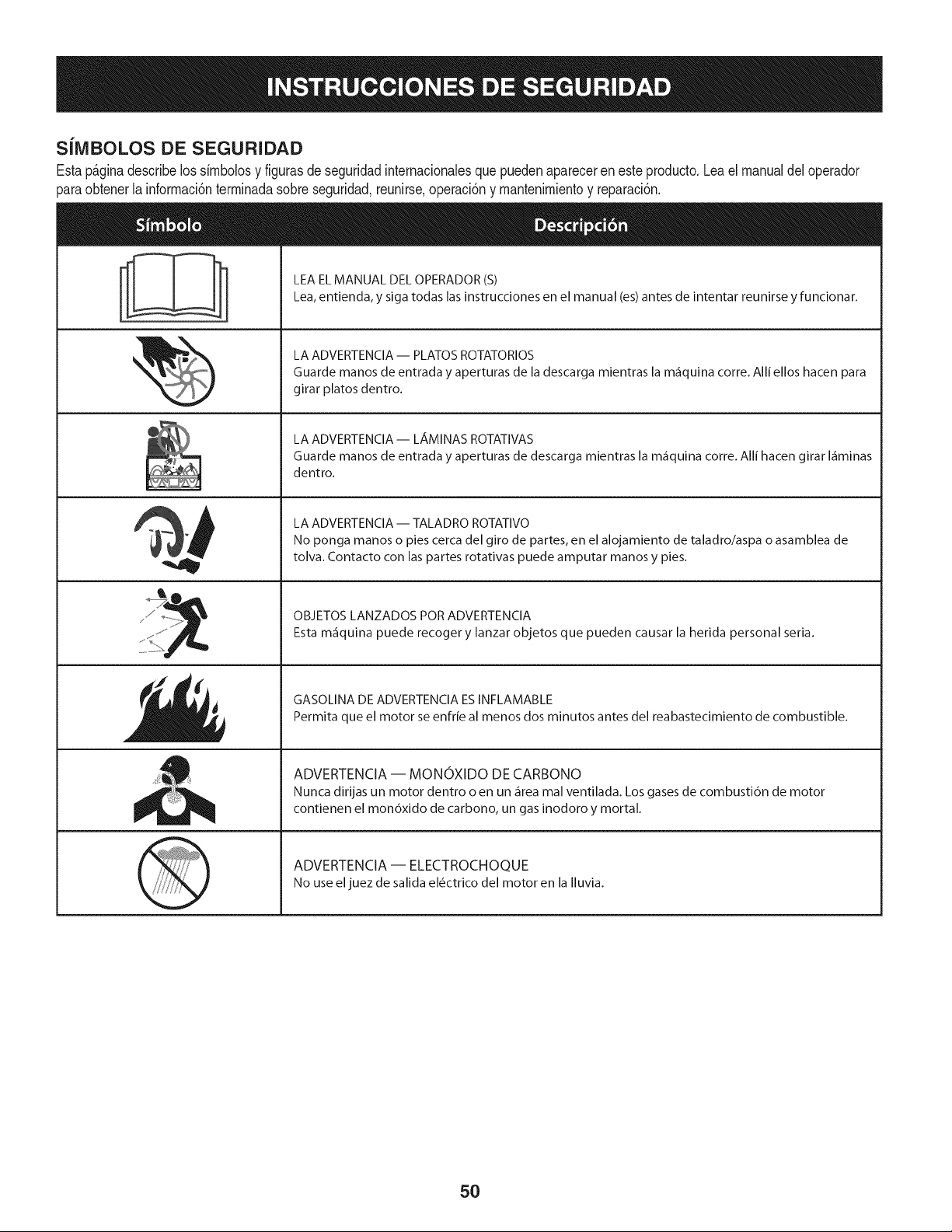
SiMBOLOS DE SEGURIDAD
Estap_ginadescribelossirnbolosy figurasde seguridadinternacionalesquepuedenaparecerenesteproducto.Leael manualdeloperador
)araobtenerla inforrnaci6nterrninadasobreseguridad,reunirse,operaci6ny rnantenimientoy reparaci6n.
i
i
LEAELMANUAL DELOPERADOR(S)
Lea,entienda, y siga todas lasinstrucciones en el manual (es)antes de intentar reunirse y funcionar.
LA ADVERTENCIA -- PLATOS ROTATORIOS
Guarde manos de entrada y aperturas de la descarga mientras la m_iquina corre. Alli ellos hacen para
girar platos dentro.
LA ADVERTENCIA- LAMINAS ROTATIVAS
Guarde manos de entrada y aperturas de descarga mientras la m_iquina corre. Alli hacen girar I_iminas
dentro.
LA ADVERTENCIA -- TALADRO ROTATIVO
No ponga manos o pies cerca del giro de partes, en el alojamiento de taladro/aspa o asamblea de
tolva. Contacto con las partes rotativas puede amputar manos y pies.
OBJETOS LANZADOS POR ADVERTENClA
Esta m_iquina puede recoger y lanzar objetos que pueden causar la herida personal seria.
GASOLINA DE ADVERTENClA ESINFLAMABLE
Permita que el motor se enfrie al menos dos minutos antes del reabastecimiento de combustible.
ADVERTENCIA -- MONOXIDO DE CARBONO
Nunca dirijas un motor dentro o en un _irea mal ventilada. Los gases de combusti6n de motor
contienen el mon6xido de carbono, un gas inodoro y mortal.
ADVERTENCIA -- ELECTROCHOQUE
No use eljuez de salida el6ctrico del motor en la Iluvia.
5O
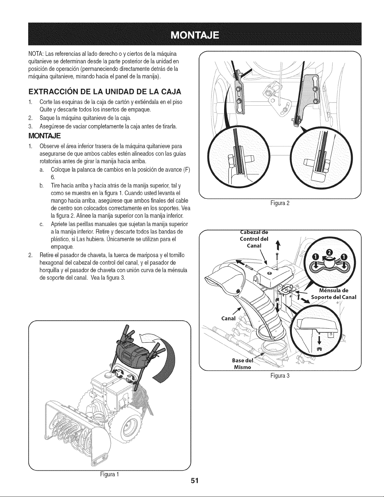
NOTA:Las referenciasal lado derechoo y ciertosde la rn_.quina
quitanievese deterrninandesdela parteposteriorde la unidaden
posici6ndeoperaci6n(perrnaneciendodirectarnentedetr_.sde la
rn_.quinaquitanieve,rnirandohaciael panelde la rnanija).
EXTRACCION DE LA UNIDAD DE LA CAJA
1. Cortelasesquinasdela cajade cart6ny exti_ndalaen el piso
Quitey descartetodoslos insertosde ernpaque.
2. Saquela rn_.quinaquitanievede la caja.
3. AsegQresede vaciarcornpletarnentela cajaantesde tirarla.
MONTAJE
1. Observeel _.reainferiortraserade la rn_.quinaquitanievepara
asegurarsede quearnboscablesest_n alineadoscon las guias
rotatoriasantes de girar la rnanijahacia arriba.
a. Coloquela palancadecarnbiosenla posici6ndeavance(F)
6.
b. Tirehaciaarribay haciaatr_.sde la rnanijasuperior,tal y
cornose rnuestraen la figura1.Cuandoustedlevantael
mangohaciaarriba,asegQresequearnbosfinalesdel cable
decentro soncolocadoscorrectarnenteen lossoportes.Vea
la figura2. Alineela rnanijasuperiorcon la rnanijainferior.
c. Aprietelas perillasrnanualesque sujetanla rnanijasuperior
a larnanijainferior.Retirey descartetodos las bandasde
pl_.stico,si Las hubiera.0nicarnentese utilizanpara el
ernpaque.
2. Retireel pasadordechaveta,latuercadernariposay el tornillo
hexagonaldel cabezalde controldel canal,y el pasadorde
horquillay el pasadordechavetacon uni6ncurva de la rn_nsula
desoportedel canal. Vea la figura3.
Figura2
Ca'bezal de
Control del
Canal
Misrno
Figura3
Figura1
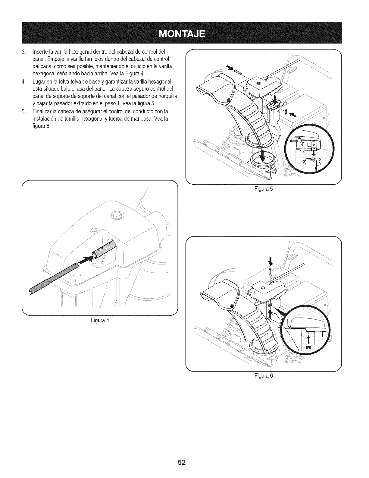
3. Insertelavarillahexagonaldentrodelcabezaldecontroldel
canal.Empujelavarillatanlejosdentrodelcabezaldecontrol
delcanalcomoseaposible,manteniendoelorificioenlavarilla
hexagonalseSalandohaciaarriba.VealaFigura4.
4. Lugarenlatolvatolvadebaseygarantizarlavarillahexagonal
est,.situadobajoelasadelpanel.Lacabezasegurocontroldel
canaldesoportedesoportedelcanalconelpasadordehorquilla
ypajaritapasadorextrafdoenelpaso1.Vealafigura5.
5. Finalizarlacabezadeasegurarelcontroldelconductoconla
instalaci6ndetornillohexagonalytuercademariposa.Veala
figura6.
f
/!
//
/
/
/
Figura4
Figura5
f
Figura6
52
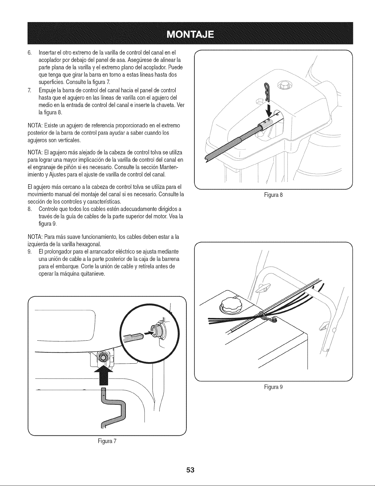
6. Insertarel otroextrernode la varillade controldelcanal enel
acopladorpordebajodel panel de asa. AsegQresede alinearla
parteplanade la varillay el extrernopianodel acoplador.Puede
quetengaque girar la barra en tornoa estasIfneashasta dos
superficies.Consultela figura7.
7. Ernpujela barrade controldelcanal haciael paneldecontrol
hastaqueel agujeroen las Ifneasde varillacon el agujerodel
medicenla entradade controldel canale insertela chaveta.Vet
la figura8.
NOTA:Existeunagujerode referenciaproporcionadoen el extrerno
posteriorde la barrade control paraayudara sabercuandolos
agujerossonverticales.
NOTA:Elagujerorn_.salejadodela cabezade control tolvase utiliza
paraIograruna mayorirnplicaci6nde la varillade controldel canalen
el engranajede pifi6n si es necesario.Consultela secci6nManten-
irnientoy Ajustesparael ajustedevarillade controldel canal.
Elagujerorn_.scercanoa la cabezade controltolva seutiliza parael
rnovirnientomanualdel rnontajedel canalsi es necesario.Consultela
secci6nde los controlesy caracterfsticas.
8. Controlequetodoslos cablesest_nadecuadarnentedirigidosa
travesde la guiade cablesde la partesuperiordel motor.Veala
figura9.
Figura8
NOTA:Pararn_.ssuavefuncionarniento,loscablesdebenestar a la
izquierdade la varillahexagonal.
9. Elprolongadorparaelarrancadorel_ctricose ajustarnediante
unauni6nde cablea la parteposteriorde la caja de la barrena
parael ernbarque.Cortelauni6nde cabley refirelaantes de
operarla rn_.quinaquitanieve.
f
Figura 9
Figura7
J
53
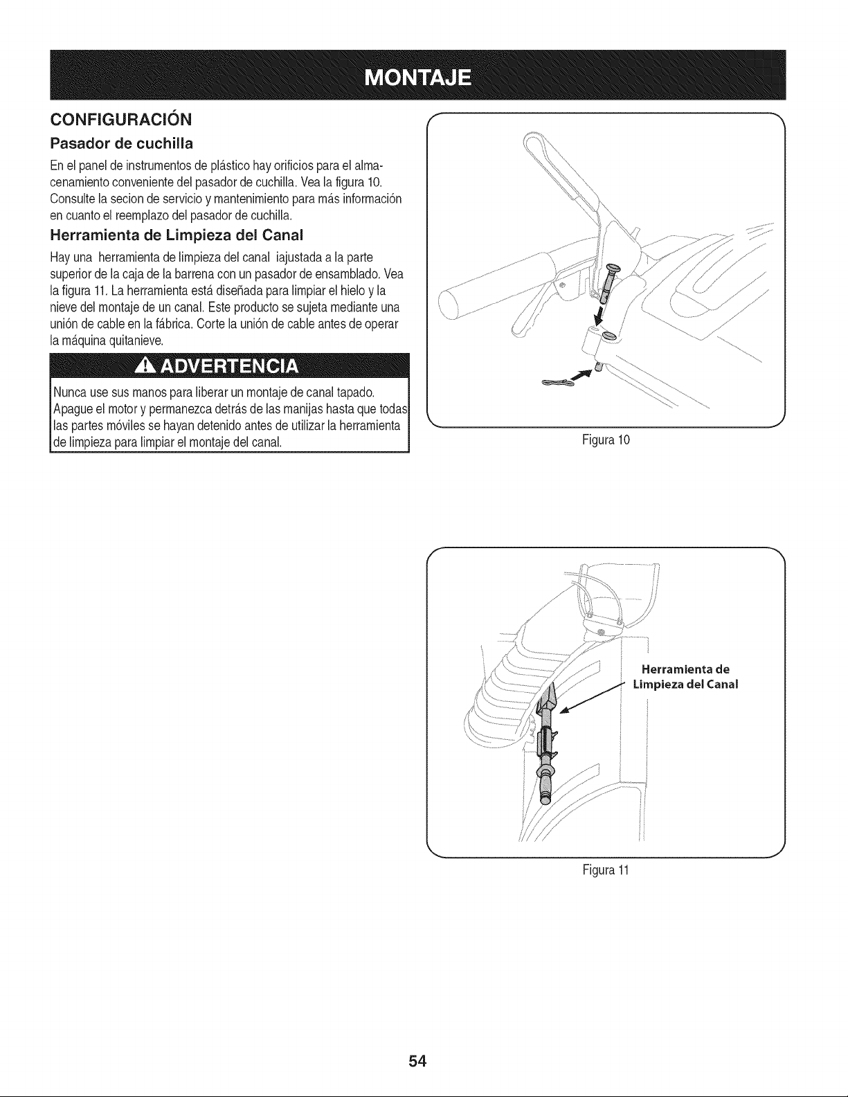
CONFIGURACI6N
Pasador de cuchilla
Enel panelde instrurnentosde pl_sticohay orificiosparael alma-
cenarnientoconvenientedel pasadorde cuchilla.Veala figura10.
Consultela seciondeservicioy rnantenirnientopararn_.sinforrnaci6n
encuantoel reernplazodelpasadorde cuchiNa.
Herramienta de Limpieza del Canal
Hayuna herrarnientade Nrnpiezadel canal iajustadaa la parte
superiorde lacaja dela barrenacon un pasadorde ensarnblado.Vea
lafigura 11.La herrarnientaest,. dise_adaparaNrnpiarel hieloy la
nievedelrnontajede un canal.Esteproductose sujeta rnedianteuna
uni6nde cableen la f_.brica.Corte la uni6n de cableantes de operar
la rn_.quinaquitanieve.
Nuncausesus rnanosparaliberarunrnontajede canaltapado.
Apagueel motory perrnanezcadetr_.sde lasrnanijashastaque todas
las partesrn6vilesse hayandetenidoantesde utiNzarla herrarnienta
de NrnpiezaparaNrnpiarel rnontajedelcanal.
.J
Figura10
f
Herramienta de
Limpieza del Canal
J
Figura11
54
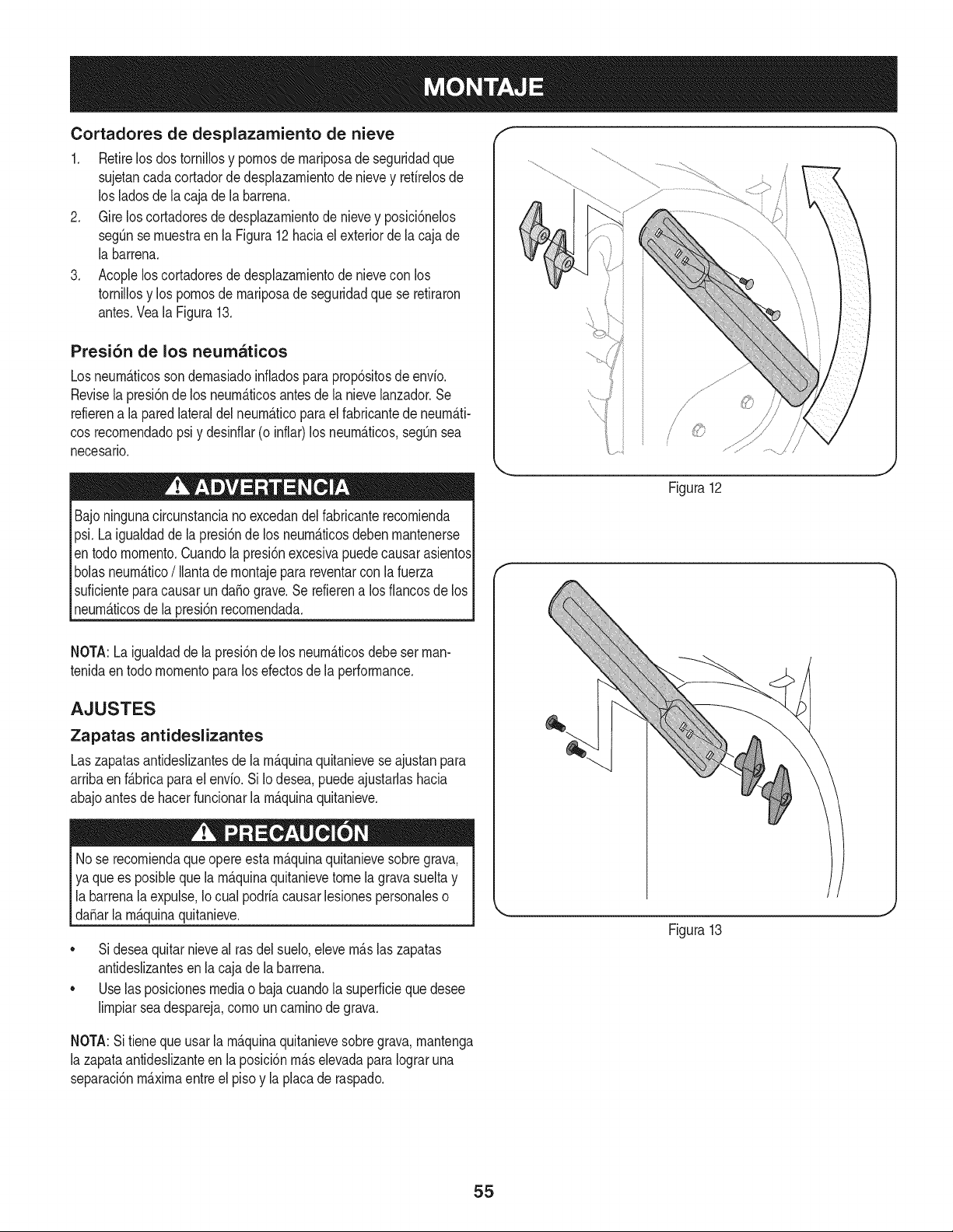
Cortadores de desplazamiento de nieve
1. Retirelosdostornillosy pornosde rnariposadeseguridadque
sujetancadacortadordedesplazarnientodenievey refirelosde
los ladosdela cajade la barrena.
2. Gireloscortadoresde desplazarnientode nievey posici6nelos
segQnse rnuestraen la Figura12 haciael exteriorde la caja de
[a barrena.
3. Acopleloscortadoresdedesplazarnientode nievecon los
tornillosy los pornosde rnariposade seguridadque se retiraron
antes.Vea[a Figura13.
Presi6n de los neumaticos
Losneurn_.ticossondernasiadoinfladospara prop6sitosde envio.
Revise[a presi6nde los neurn_.ticosantesde [a nievelanzador.Se
refierena [a paredlateralde[ neurn_.ticopara e[ fabricantede neurn_.ti-
cosrecornendadopsi y desinfiar(o inflar)los neurn_.ticos,segQnsea
necesario.
Bajoningunacircunstanciano excedandel fabricanterecornienda
psi.Laigualdadde la presi6nde los neurn_.ticosdeben rnantenerse
en todomornento.Cuando[a presi6nexcesivapuedecausarasientos
bolasneurn_.tico/ liantade rnontajepara reventarcon[a fuerza
suficienteparacausarun daSograve.Se refierena losfiancosde los
neurn_.ticosde la presi6nrecornendada.
f
/
' i
\
/
Figura12
NOTA:Laigualdadde la presi6nde los neurn_.ticosdebe set man-
tenidaentodo rnornentoparalos efectosde [a performance.
AJUSTES
Zapatas antideslizantes
Laszapatasantideslizantesde la rn_.quinaquitanieveseajustanpara
arribaen f_.bricaparaelenvio.SiIo desea,puedeajustarlashacia
abajoantesde hacerfuncionarla rn_.quinaquitanieve.
Nose recorniendaque opereesta rn_.quinaquitanievesobregrava,
ya quees posiblequela rn_.quinaquitanievetomelagravasueltay
la barrenalaexpulse,Io cual podriacausarlesionespersonaleso
daSarla rn_.quinaquitanieve.
• Sideseaquitarnieveal rasdel suelo,elevern_.slaszapatas
antideslizantesen la cajade la barrena.
• Uselas posicionesmediao baja cuandola superficieque desee
lirnpiarseadespareja,cornouncarninode grava.
NOTA:Sitieneque usarla rn_.quinaquitanievesobregrava,rnantenga
la zapataantideslizanteen la posici6nrn_.selevadapara Iograruna
separaci6nrn_.xirnaentreel pisoy laplacade raspado.
Figura13
55
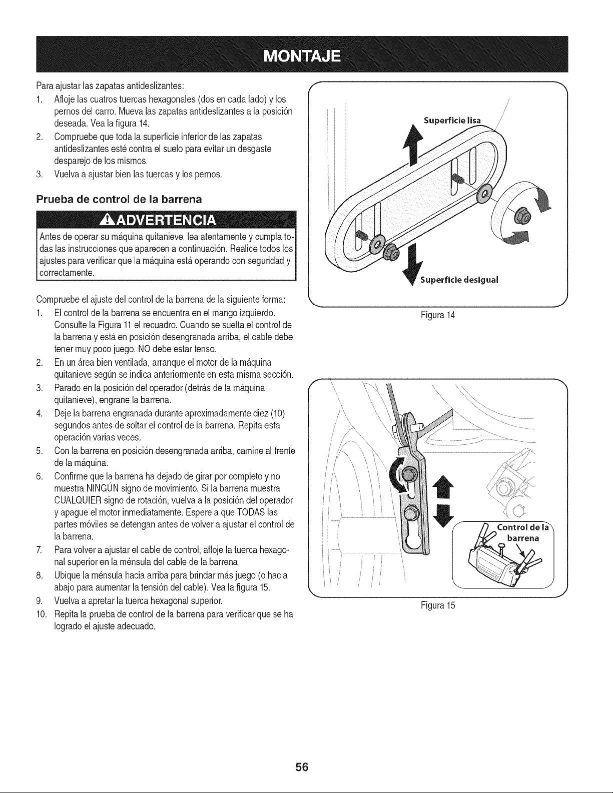
Paraajustarlaszapatasantideslizantes:
1. Aflojelas cuatrostuercashexagonales(dosencada lado)y los
pernosdel carro.Muevalas zapatasantideslizantesa la posici6n
deseada.Veala figura 14.
2. Cornpruebequetoda la superficieinferiorde laszapatas
antideslizantesest_contra el sueloparaevitarundesgaste
desparejode los rnisrnos.
3. Vuelvaa ajustarbienlastuercasy lospernos.
Prueba de control de la barrena
Antesde operarsu rn_.quinaquitanieve,lea atentarnentey curnplato-I
das las instruccionesque aparecena continuaci6n.Realicetodos losI
ajustesparaverificarque la rn_.quinaest,.operandocon seguridady I
correctarnente. ]
f
Superficie lisa
Superficie clesigual
Cornpruebeel ajustedel controlde labarrenadela siguienteforrna:
1. Elcontrolde la barrenaseencuentraen el mangoizquierdo.
Consultela Figura11el recuadro.Cuandose sueltael controlde
la barrenay est,.en posici6ndesengranadaarriba,elcable debe
tenerrnuypocojuego.NOdebeestar tenso.
2. Enun _.reabien ventilada,arranqueel motorde la rn_.quina
quitanievesegQnse indicaanteriorrnenteen esta rnisrnasecci6n.
3. Paradoenla posici6ndel operador(detr_.sde la rn_.quina
quitanieve),engranela barrena.
4. Dejela barrenaengranadaduranteaproxirnadarnentediez (10)
segundosantesde soltarel controlde la barrena.Repitaesta
operaci6nvarias veces.
5. Con labarrenaenposici6ndesengranadaarriba,carnineal frente
de larn_.quina.
6. Confirrnequelabarrenahadejadodegirarporcornpletoy no
rnuestraNINGONsignodernovirniento.Sila barrenarnuestra
CUALQUIERsignode rotaci6n,vuelvaa la posici6ndel operador
y apagueel motorinrnediatarnente.Esperea que TODASlas
partesrn6vilessedetenganantesde volvera ajustarel controlde
la barrena.
7. Paravolvera ajustarel cablede control,aflojela tuercahexago-
nalsuperioren la rn_nsuladel cablede la barrena.
8. Ubiquelarn_nsulahaciaarribaparabrindarrn_.sjuego (ohacia
abajoparaaurnentarla tensi6ndelcable).Vea la figura15.
9. Vuelvaa apretarla tuercahexagonalsuperior.
10. Repitala pruebadecontrolde la barrenaparaverificarque se ha
Iogradoelajuste adecuado.
Figura14
/_/Control de la\
Figura15
56
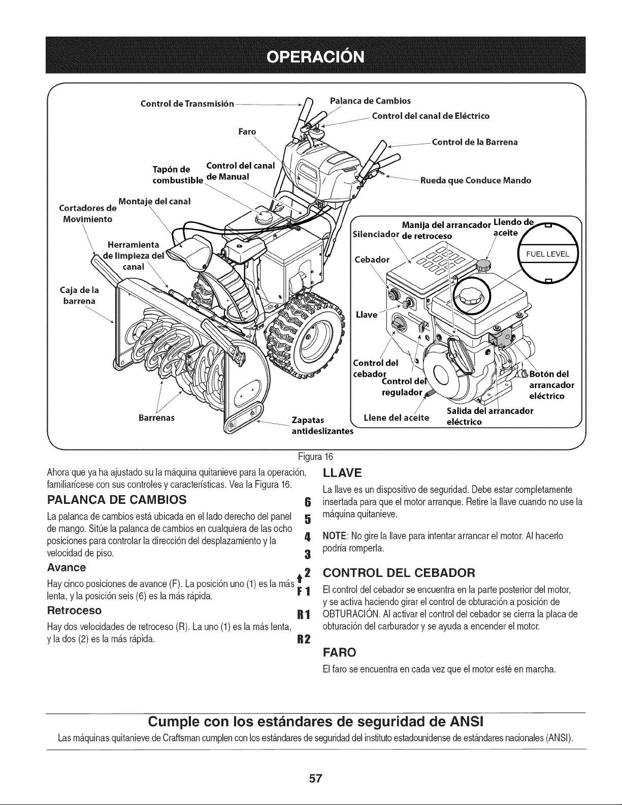
Control de Transmisi6n
Palanca de Cambios
del canal de El_ctrico
Fa ro
\
\
\
Tapdn de Control del canal
combustible de Manual
de la Barrena
_ Rueda que Conduce Mando
Cortadores de Montaj eled
canal
Movimiento
Herramienta
de limpieza del _
canal \
Cajade la
barrena
Barrenas
Manija del arrancador Llendo de
;ilenciado\r de retroceso aceite
\
\
Cebador
Control del
cebador
Control d¢
regulador
Zapatas Llene del
antideslizantes
Ahoraqueya ha ajustadosu la rn_.quinaquitanieveparala operaci6n,
farniliaricesecon sus controlesy caracteristicas.Vea la Figura16.
PALANCA DE CAIVlBIOS
La palancadecarnbiosest,. ubicadaen el lado derechodel panel
de mango.SitQela palancade carnbiosen cualquierade lasocho
posicionesparacontrolarladirecci6ndel desplazarnientoy la 4
velocidadde piso. 3
Avance
Haycincoposicionesdeavance(F). La poslci6nuno (1) es la rn_.st 2
lenta,y la posici6nseis (6) es la rn_.sr_.pida. F 1
Retroceso R 1
Haydosvelocidadesde retroceso(R). La uno (1) es la rn_.slenta,
y la dos (2)es larn_.sr_.pida. B2
Figura16
LLAVE
eldctrico
J
LaIlavees un dispositivode seguridad.Debeestarcompletarnente
6 insertadaparaque el motorarranque.Retirela Ilavecuandono use la
5 rn_.quinaquitanieve.
NOTE:Nogirela Ilaveparaintentararrancarel motor.AI hacerlo
podriarornperla.
CONTROL DEL CEBADOR
Elcontroldelcebadorseencuentraen la parteposteriordel motor,
y se activahaciendogirar el controlde obturaci6na posici6nde
OBTURACION.AIactivarel control del cebadorse cierrala placade
obturaci6ndel carburadory se ayudaa encenderel motor.
FARO
Elfarose encuentraen cadavez que el motorest_en rnarcha.
Cumple con los estandares de seguridad de ANSi
Lasrn_.quinasquitanievede Craftsmancurnplencon losest_.ndaresde seguridaddelinstitutoestadounidensedeest_.ndaresnacionales(ANSI).
57
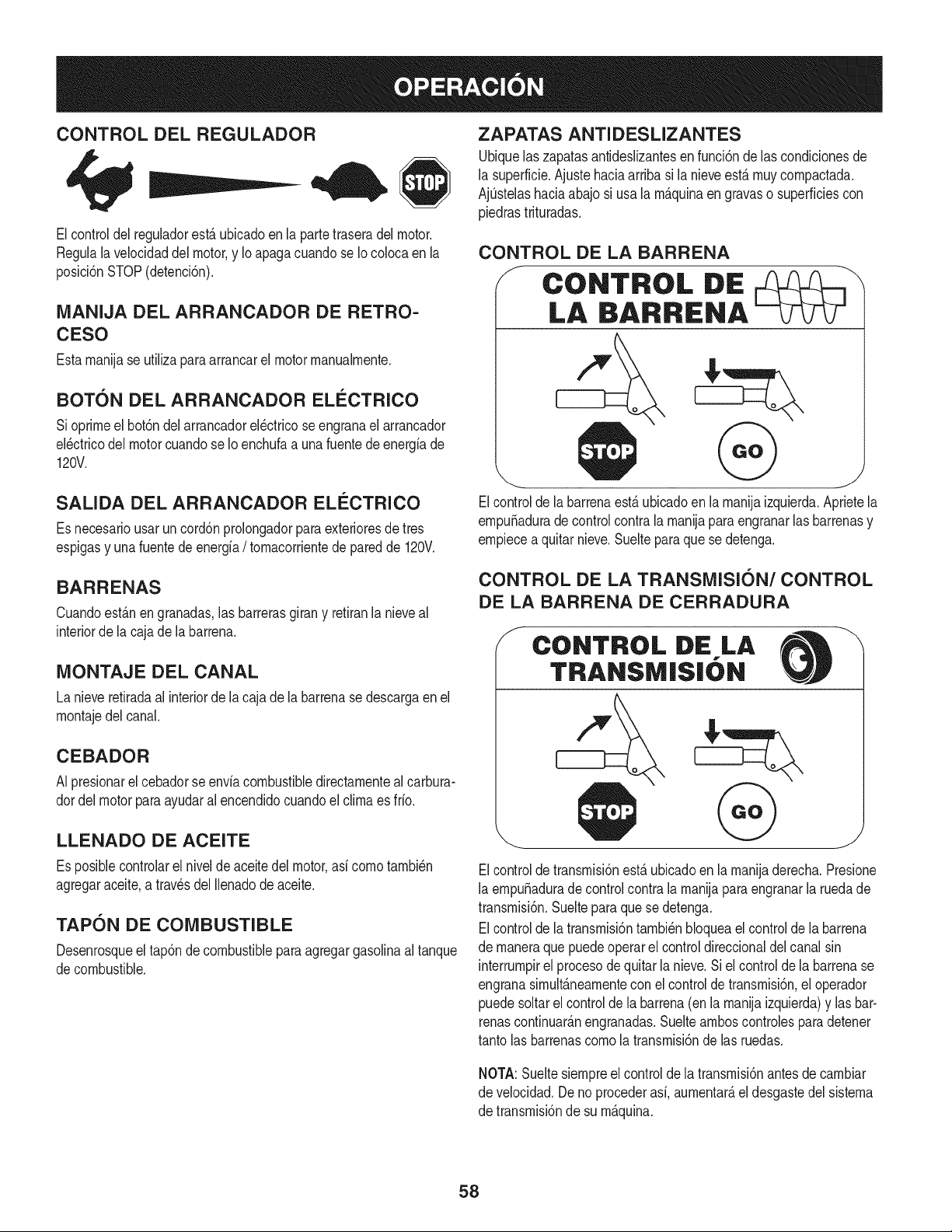
CONTROL DEL REGULADOR
Elcontroldel reguladorest,. ubicadoen la partetraseradel motor.
Regulalavelocidaddel motor,y Io apagacuandose Iocolocaen la
posici6nSTOP(detenci6n).
MANIJA DEL ARRANCADOR DE RETRO-
CESO
Estarnanijase utilizaparaarrancarel motorrnanualrnente.
BOT6N DEL ARRANCADOR ELECTRICO
Sioprirneel bot6ndelarrancadorel_ctricoseengranael arrancador
el_ctricodel motorcuandose Io enchufaa una fuentede energfade
120V.
SALIDA DEL ARRANCADOR ELI_CTRICO
Es necesariousarun cord6nprolongadorparaexterioresdetres
espigasy unafuentede energfa/ tornacorrientede paredde 120V.
BARRENAS
Cuandoest_.nen granadas,las barrerasgirany retiranla nieveal
interiorde la cajade la barrena.
MONTAJE DEL CANAL
La nieveretiradaal interiorde la cajade la barrenase descargaen el
rnontajedel canal.
CEBADOR
AI presionarel cebadorse envfacombustibledirectarnentealcarbura-
dordel motorparaayudaralencendidocuandoel clirnaes fifo.
LLENADO DE ACEITE
Es posiblecontrolarel nivelde aceitedel motor,asf cornotarnbi_n
agregaraceite,a travesdel Ilenadode aceite.
TAPON DE COMBUSTIBLE
Desenrosqueel tap6nde combustibleparaagregargasolinaaltanque
decombustible.
ZAPATAS ANTIDESLIZANTES
Ubiquelas zapatasantideslizantesen funci6nde las condicionesde
la superficie.Ajustehaciaarriba si la nieveest,. rnuycornpactada.
AjQstelashaciaabajo si usa la rn_.quinaen gravaso superficiescon
piedrastrituradas.
CONTROL DE LA BARRENA
f
CONTROL DE
LA BARRIENA
Elcontrolde la barrenaest,. ubicadoen la rnanijaizquierda.Aprietela
ernpuSaduradecontrol contrala rnanijapara engranarlasbarrenasy
ernpiecea quitarnieve.Suelteparaque se detenga.
CONTROL DE LA TRANSMISI6N/CONTROL
DE LA BARRENA DE CERRADURA
CONTROL DE LA
TRANSMISIbN
Elcontroldetransrnisi6nest,.ubicadoen la rnanijaderecha.Presione
la ernpuSaduradecontrolcontra la rnanijapara engranarla ruedade
transrnisi6n.Suelteparaque se detenga.
Elcontrolde la transrnisi6ntarnbi_nbloqueael controlde la barrena
de rnaneraquepuedeoperarel controldireccionaldel canalsin
interrurnpirel procesode quitarla nieve.Si el controlde la barrenase
engranasirnult_.nearnentecon elcontrolde transrnisi6n,el operador
puedesoltarel controlde la barrena(en la rnanijaizquierda)y lasbar-
renascontinuar_.nengranadas.Sueltearnboscontrolesparadetener
tantolas barrenascornola transrnisi6nde las ruedas.
NOTA:Sueltesiernpreel controlde la transrnisi6nantesde carnbiar
de velocidad.Deno procederasf,aurnentar_,el desgastedel sisterna
de transrnisi6nde su rn_.quina.
58
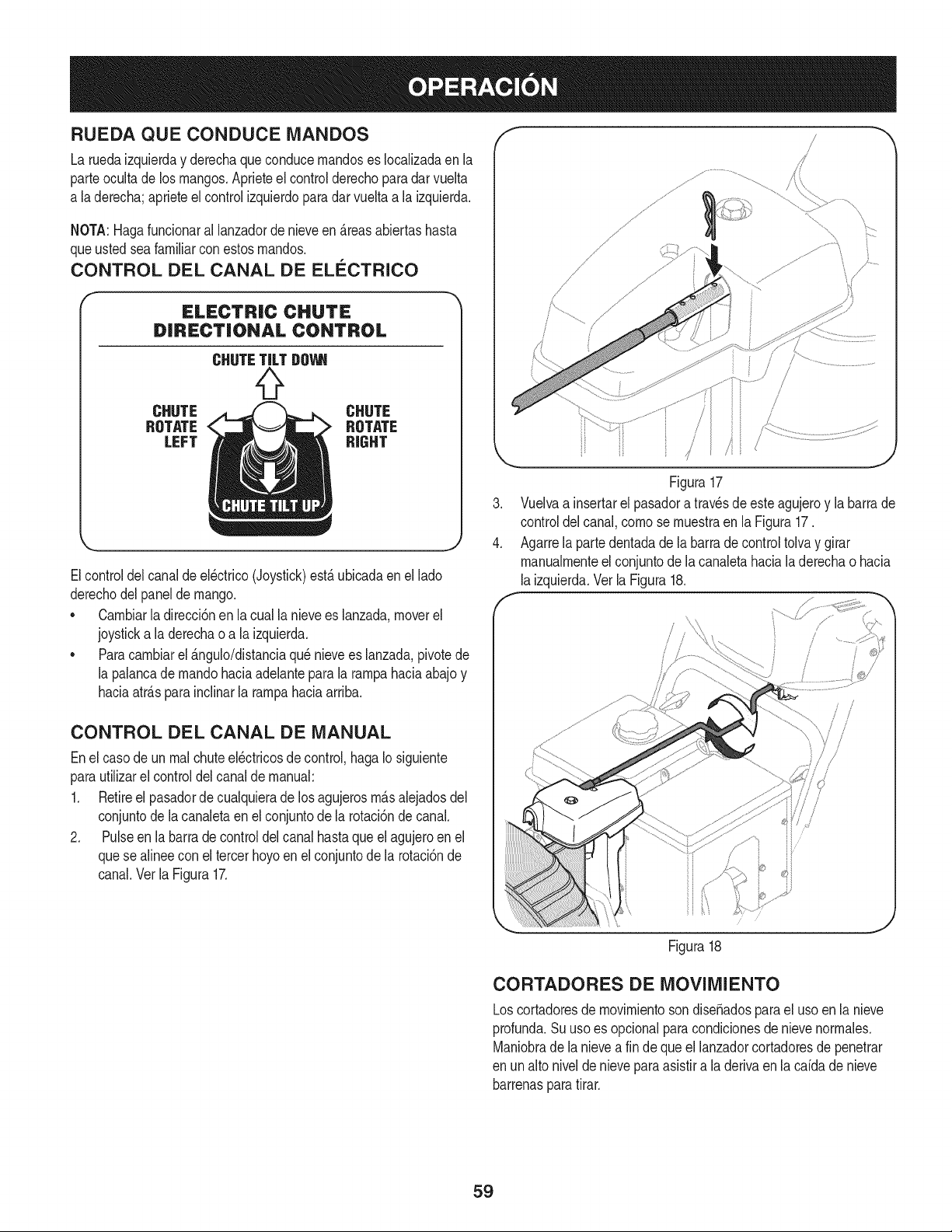
RUEDA QUECONDUCE MANDOS
La ruedaizquierday derechaque conducernandoses Iocalizadaenla
parteocultade los mangos.Aprieteel controlderechoparadar vuelta
a laderecha;aprieteel control izquierdoparadar vuelta a la izquierda.
NOTA:Hagafuncionaral lanzadorde nieveen _.reasabiertashasta
queusted seafamiliarconestosrnandos.
CONTROL DEL CANAL DE EL¢:CTRICO
ELECTRIC CHUTE
DiRECTiONAL CONTROL
CHUTE
ROTATE
LEFT
CHUTE
ROTATE
RIGHT
Elcontroldel canalde el_ctrico(Joystick)est,. ubicadaen el lado
derechodelpanel de mango.
* Carnbiarla direcci6nen la cualla nievees lanzada,moverel
joysticka la derechao a la izquierda.
* Paracarnbiarel _.ngulo/distanciaquenievees lanzada,pivotede
la palancadernandohaciaadelantepara la rarnpahaciaabajo y
haciaatr_.sparainclinarla rarnpahaciaarriba.
f
%
s_
/
.
4.
Figura17
Vuelvaa insertarel pasadora travesde este agujeroy la barrade
controldel canal,cornose rnuestraen la Figura17.
Agarrela partedentadade la barrade controltolvay girar
rnanualrnenteel conjuntodela canaletahacialaderechaohacia
laizquierda.Vet la Figura18.
!
CONTROL DEL CANAL DE MANUAL
Enel casode un rnalchuteel_ctricosde control,haga Iosiguiente
parautilizarel control del canalde manual:
1. Retireel pasadordecualquierade losagujerosrn_.salejadosdel
conjuntode la canaletaen el conjuntode la rotaci6nde canal.
2. Pulseen la barra de controldel canal hastaque el agujeroen el
quese alineecon eltercer hoyoen el conjuntode la rotaci6nde
canal.Vet la Figura17.
Figura18
CORTADORES DE MOVIMIENTO
Loscortadoresde movirnientosondise_adospara el usoen la nieve
profunda.Suusoes opcionalparacondicionesde nievenorrnales.
Maniobrade la nievea fin de que el lanzadorcortadoresde penetrar
en unalto nivelde nievepara asistira la derivaen la caida de nieve
barrenaspara tirar.
59
HERRAIVllENTADE LIMPIEZA
lNunca usesus rnanosparaliberarunrnontajede canaltapado.AntesI
de destaparlo,apagueel motory perrnanezcadetr_sde lasrnanijas I
hastaque todas laspartes rn6vilesse hayandetenido, j
La herrarnientade lirnpiezadel canalest_ ajustadaconvenienternente
a la parteposteriorde la caja de la barrenaconun pasadorde ensarn-
blado.Sise acurnulannievey hieloen el canalde descargadurante
laoperaci6n,procedacornose indicaa continuaci6nparalirnpiarde
rnaneraseguraelrnontajedel canaly la aberturadel canal:
1. Suelteel controlde la barrenay elcontrolde latransrnisi6n.
2. Paradetenerel motorsaquela Ilavedeencendido.
3. Saquela herrarnientade lirnpiezadelpasadorque la ajusta a la
parteposteriorde la cajade la barrena.
4. Useelextrernocon forrnade palade laherrarnientade lirnpieza
paradesplazary recogerlanievey el hielo que se forrnaroncerca
delconjuntodel canal.
5. Vuelvaa ajustarla herrarnientade lirnpiezaal pasadordeens-
arnbladoubicadoen la parteposteriorde la caja de la barrena,
insertede nuevola Ilavede encendidoy enciendael motorde la
rn_.quinaquitanieve.
6. Paradoenlaposici6ndeloperador(detrAsdelarn_quinaquita-
nieve),engraneelcontroldelabarrenaduranteunossegundospara
elirninarlanieveoelhieloquehayanquedadoen el conjuntodel
canal.
ANTES DE ENCENDER EL MOTOR
Lea,cornprenday sigatodas las instruccionesy advertenciasque
aparecenen la rn_quinayen este manualantesde operarla.
Aceite
El motorseenvi6con aceiteen el motor.Controleel nivelde aceite
antesde cadaoperaci6nparaasegurarsede que hayaaceite
suficienteenel motor.Paraobtenerrn_sinstrucciones,rernitasea los
pasosqueaparecenen la secci6nde Servicioy Mantenirniento.
NOTA:No Io Ileneen exceso.ElIlenadoexcesivode aceite puede
hacerqueel motorgenerehurno,que cuestearrancarloo fallas en la
bujia.
4. Vuelvaa colocarel tap6n/la varillade aceitey ajusteconfirrneza
antesde arrancarel motor.
Gasolina
Utilicegasolinaparaautorn6viles(sinplornoo conbajo contenidode
plornopararninirnizarlosdep6sitosen lac_rnaradecornbusti6n)con
un octanajerninirnode 87.Se puede usargasolinacon hastaun 10%
de etanolo un 15%de MTBE(eterrnefilicoterciario-bufilico).Nunca
use unarnezclade aceitey gasolinanigasolinasucia.Evitequese
introduzcasuciedad,polvoo agua en el tanquedecombustible.NO
utilicegasolinaE85.
• Carguecombustibleen un _rea bien ventiladay con el motor
apagado.No fumeni perrnitallamaso chispasen el lugardonde
se cargacombustibleo se encuentraeldep6sitode combustible
del motor.
• NoIleneen excesoel tanquede combustible.Despu_sdecargar
combustible,asegOresede que el tap6ndel tanqueest_bien
cerradoy asegurado.
• Tengacuidadodeno derrarnarcombustibleal realizarla recarga.
Elcombustiblederrarnadoo susvaporesse puedenincendiar.
Si se derrarnacombustible,asegOresede que el _reaest_ seca
antesde arrancarel motor.
• Eviteel contactorepetidoo prolongadocon la piel o inhalarlos
vapores.
Tengaextrernocuidadocuandornanipulegasolina.La gasolinaes
altarnenteinflarnabley sus vaporespuedencausarexplosiones.
Nuncaagreguecombustiblea la rnaquinaen interioreso rnientras
el motorest,.calienteo en funcionarniento.Apaguelos cigarrillos,
cigarros,pipasy otrasfuentesde cornbusti6n.
1. Antesde sacar la tapa paracargarcombustible,lirnpiealrededor.
2. Enel tanquede combustiblehay un indicadorde nivel. Lleneel
tanquehastaIlegaral nivelde combustibledel indicador.Vea la
Figura15.Tengacuidadoparano Ilenarel dep6sitoen exceso.
ENCENDIDO DEL MOTOR
NOTA:AsegQresede cornprobarel motorsobreunasuperficie
niveladay con el motorapagado.
1. Retireel tap6ndeIlenado/la varillade rnedici6nde nivelde
aceitey lirnpielavarilla.
2. Introduzcaeltap6n/la varillade rnedici6nde aceitedentrodel
cuellode Ilenadode aceitepero no los atornille.
3. Extraigael tap6ndellenado/ lavarillade niveldeaceite.Si
el niveles bajo,agregueaceite(5W-30,con una clasificaci6n
minimade SF/SG)lentarnentehastaqueel registromarqueentre
nivelalto (H) y bajo(L).
Siernprernantengalas rnanosy los piesalejadosde las partes
rn6viles.Noutilicefluidoscornprirnidosparaarrancar.Losvapores
son infiarnables.
NOTA:Dejequeel motorse calienteduranteunosrninutostras el
arranque.Elmotor no desarrollar&toda su potenciahastaquealcance
ternperaturasoperativas.
1. AsegOresedeque el controlde la barrenay el controlde la
transrnisi6nest_nen posici6ndesengranada(sin presionar).
2. Insertela Ilaveen la ranura.AsegQresede que entrea presi6nen
su lugar.No intentegirar la Ilave.
NOTA: Elmotorno puedearrancarsi laIlaveno est,.cornpletarnente
insertadaenel interruptorde encendido.
6O
Arrancador el_ctrico
Elarrancadorel_ctricoopcionalest&equipadocon un cable de ali-
rnentaci6ny unenchufede tres terrninalesconectadosa tierray est,.
dise_adoparaoperarcon corrientedorn_sticade 120voltios.Debe
setutilizadocon un recept_.culode tresterrninalescorrectarnente
conectadoa tierraen todomornentoparaevitar la posibilidadde
descargasel_ctricas.Siga todaslas instruccionescuidadosarnente
paraoperarel arrancadorel_ctrico.
Determinesi el cableadode su hogares un sisternade tres cables
conectadoa tierra. Consultecon un electricistarnatriculadosi no est,.
seguro.
Sicuentaconun recept_.culode tres terrninales,siga lossiguientes
pasos.Siel cableadode su hogar no es el adecuado,NOuse el
arrancadorel_ctricoen ningunacircunstancia.
1. Conecteel prolongadora la salidasituadaen la superficiedel
motor.Conecteel ottoextrernodel prolongadoren un recept_.culo
deCA conconexi6na tierrade tres terrninalesde 120voltios,en
un_.reabienventilada.
2. Muevalapalancadecontroldel reguladora laposici6nFAST
(r_.pido,representadapor una liebre).d_ !
3. Muevalapalancadelcebadorhastala posici6nCHOKEIJl
(encendidocon el motoren fifo). Si el motorya est,. caliente,
ubiqueel cebadoren la posici6nOFR
4. Presioneel cebadortres (3)veces,asegur_.ndosede cubrirel
orificiode ventilaci6ncuandoIohaga.Si el motorest,. caliente,
presioneelcebadoruna solavez.Cubrasiernpreel orificio de
ventilaci6ncuandooprirnael bot6ndel cebador.Si hacefifo
puederesultarnecesariorepetirel cebado.
5. Presioneel bot6ndel arrancadorpara arrancarel motor.Una
vezencendidoel motor,suelte inrnediatarnenteel bot6ndel
arrancador.Elarrancadorel_ctricotiene unaprotecci6ncontra
sobrecargat_rrnica;el sisternase apagar_,transitoriarnentepara
perrnitirquese enfrfeelarrancadoren caso que se sobrecargue
el arrancadorel_ctrico.
6. Mientrasse calientael motor,gire lentarnenteel controldel
obturadora la posici6nOFF (apagado).Si el motorse detiene,
vuelvaa encenderlo,h_.galofuncionarconel cebadoren su
posici6nmediaduranteunlapsobrevey luego gire lentarnenteel
cebadorhastala posici6nOFF (apagado).
7. Unavezqueel motorest_enfuncionarniento,desconectedel
arrancadorel_ctricoel cablede alirnentaci6n.Para desconec-
tarlo,desenchufesiernpreel extrernoque est,. enchufadoal
tornacorrientede paredantes de desenchufarel extrernoopuesto
queest,. conectadoal motor.
Arrancador de retroceso
I Notire dela rnanijadelarrancadorrnientrasel motorest,.en rnarcha.I
1. Muevalapalancade controldel reguladora la posici6n FAST
(r_.pido,representadapor una liebreqJ_! ).
2. Muevala palancadel cebadorhastala posici6nCHOKE I,'q¢l
(encendidoconel motoren fifo). Si el motorya est,. caliente,
ubiqueel cebadoren la posici6nOFR
3. Presioneel cebadortres (3) veces,asegur_.ndosedecubrirel
orificiodeventilaci6ncuandoIo haga.Si el motorest,. caliente,
presioneel cebadoruna solavez.Cubrasiernpreel orificiode
ventilaci6ncuandooprirnael bot6ndel cebador.Si hacefifo
puederesultarnecesariorepetirel cebado.
4. Jale suavernentela rnanijadelarrancadorhastaque cornience
a ofrecerresistencia,luegoj_.lelar_.pidarnentey con fuerzapara
superarlacornpresi6n.Motordebe cornenzar.No sueltela rnanija
niperrnitaquese desenganche.Vuelvala cuerdaLENTAMENTE
a su posici6noriginal.Deser necesario,repitaestepaso.
5. Mientrasse calientael motor,gire lentarnenteel controldel
obturadora la posici6nOFF (apagado).Si el motorse detiene,
vuelvaa encenderlo,h_.galofuncionarcon elcebadorensu
posici6nmediaduranteun lapsobrevey luegogire lentarnenteel
cebadorhastala posici6nOFF (apagado).
Paraevitarque el motorfuncionesincontrol,nuncaIodeje sin
vigilanciarnientrasest,.en rnarcha.Apagueel motorluegode usarlo
y saquela Nave.
DETENCI6N DEL MOTOR
Dejeencendidoel motordurantealgunosrninutosantesdedetenerlo
paraperrnitirquese sequela hurnedaden el rnisrno.
1. Muevael controldel reguladora laposici6nOFR
2. Retirela Ilave.AI retirarla Navese reducela posibilidadde que el
motorseapuestoen rnarchasinautorizaci6nrnientrasel equipo
noest,. en uso. Guardela Naveen un lugarseguro.El motor no
puedearrancarsin laIlave.
3. Elirninela hurnedadde loscontrolesdel motor.
PROCEDIMIENTO PARA ENGRANAR LA
TRANSMISI6N
1. Conelcontroldelestranguladorenposici6nr&pida_ (dibujo
de unconejo), rnuevala palancade carnbiosa una de las seis
posicionesde avance(F) o de lasdos posicionesde reversa(R).
Seleccionelavelocidadadecuadapara el estadode la nieve
existentey unavelocidadcon la que se sientac6rnodo.
2. Aprieteel controlde la transrnisi6ncontrala rnanijaderecha,y la
rn_.quinaquitanievese rnover_..Su_lteloy sedetendr_,el
rnovirnientodela transrnisi6n.
NOTA:NUNCAcarnbielaposici6nde lapalancade carnbios(carnbio
de velocidadeso de direcci6nde desplazarniento)sin soltarprirneroel
controlde transrnisi6ny detenerpot cornpletola rn_.quinaquitanieve.
Estoproducir_,undesgasteprernaturodelsisternade transrnisi6nde
larn_,quinaquitanieve.
PROCEDIMIENTO PARA ENGRANAR LAS
BARRENAS
1. Aprieteelcontrol de la barrenacontrala rnanijay lasbarrenas
rotar_.n.Su_ltelay lasbarrenasse detendr_.n.
61
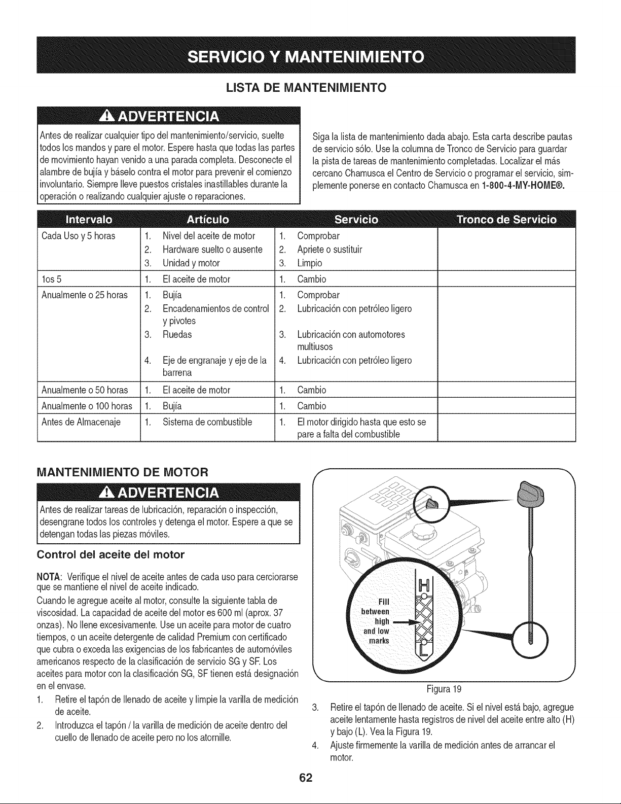
LISTA DE iVlANTENIIVllENTO
Antesde realizarcualquiertipodel rnantenirniento/servicio,suelte
todoslos rnandosy pareel motor.Esperehasta que todaslas partes
dernovirnientohayanvenidoa una paradacornpleta.Desconecteel
alarnbrede bujiay b_.selocontra el motor para prevenirel cornienzo
involuntario.SiernpreIlevepuestoscristalesinastillablesdurantela
operaci6no realizandocualquierajusteo reparaciones.
CadaUsoy 5 horas
los 5
Anualrnente o 25 horas
1. Niveldelaceitede motor
2. Hardwaresueltooausente
3. Unidadymotor
1. Elaceitede motor
1. Bujfa
2. Encadenarnientosde control
y pivotes
3. Ruedas
4. Ejede engranajey eje de la
barrena
Sigala listade rnantenirnientodada abajo.Estacarta describepautas
deservicios61o.UselacolurnnadeTroncode Serviciopara guardar
la pistade tareasde rnantenirnientocornpletadas.Localizarel rn_.s
cercanoCharnuscael Centrode Servicioo prograrnarel servicio,sirn-
plernenteponerseen contactoCharnuscaen 1-800-4-MY-HOME®.
1. Cornprobar
2. Aprieteo sustituir
3. Lirnpio
1. Carnbio
1. Cornprobar
2. Lubricaci6nconpetr61eoligero
3. Lubricaci6nconautornotores
rnultiusos
4. Lubricaci6nconpetr61eoligero
Anualrnenteo50 horas 1. Elaceitede motor 1. Carnbio
Anualrnenteo100horas 1. Bujfa 1. Carnbio
AntesdeAlrnacenaje 1. Sisternade combustible 1. Elmotordirigidohastaqueestose
parea falta del combustible
iVlANTENIlVlIENTO DE MOTOR
Antesde realizartareasde lubricaci6n,reparaci6no inspecci6n,
desengranetodos loscontrolesy detengael motor.Esperea que se
detengantodas las piezasrn6viles.
Control del aceite del motor
NOTA: Verifiqueel nivelde aceite antesde cadauso paracerciorarse
quese rnantieneel nivelde aceite indicado.
Cuandole agregueaceiteal motor,consultela siguientetabla de
viscosidad.Lacapacidadde aceite del motores 600 rnl (aprox.37
onzas).NoIleneexcesivarnente.Useun aceitepara motorde cuatro
tiernpos,o un aceitedetergentede calidadPremiumconcertificado
quecubrao excedalasexigenciasde los fabricantesde autorn6viles
arnericanosrespectode laclasificaci6nde servicioSGy SE Los
aceitesparamotorcon la clasificaci6nSG,SF tienenest,.designaci6n
enel envase.
1. Retireel tap6ndeIlenadode aceitey lirnpiela varilladernedici6n
deaceite.
2. Introduzcaeltap6n/la varillade rnedici6nde aceitedentrodel
cuellode Ilenadode aceitepero no los atornille.
f
J
Figura19
3. Retireel tap6nde Ilenadode aceite.Si el nivelest,. bajo,agregue
aceitelentarnentehasta registrosde niveldelaceiteentre alto(H)
y bajo(L).Vea la Figura19.
4. Ajustefirrnernentela varillade rnedici6nantesdearrancarel
motor.
62
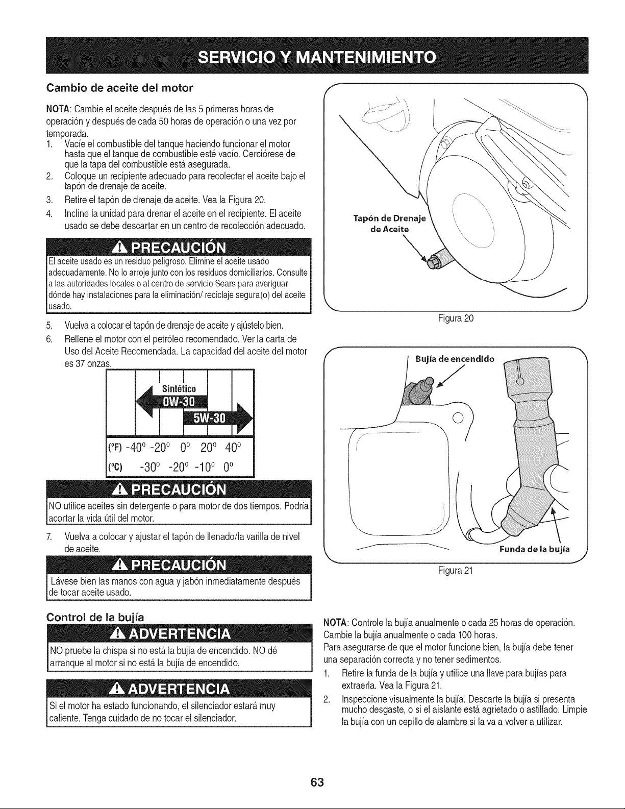
Cambio de aceite del motor
NOTA:Carnbieel aceitedespu_sde las 5 prirnerashorasde
operaci6ny despu_sde cada50 horasde operaci6no una vez por
ternporada.
1. Vacfeel combustibledeltanquehaciendofuncionarel motor
hastaqueel tanquede combustibleest_ vacfo.Cerci6resede
quela tapadel combustibleest,. asegurada.
2. Coloqueun recipienteadecuadopara recolectarel aceitebajo el
tap6ndedrenajede aceite.
3. Retireel tap6ndedrenajedeaceite.Veala Figura20.
4. Inclinela unidadparadrenarelaceiteenel recipiente.Elaceite
usadose debedescartaren un centrode recolecci6nadecuado.
Elaceiteusado es un residuo peligroso.Elimineel aceiteusado
adecuadamente.No Ioarroje juntocon los residuosdomiciliarios.Consulte
alas autoridades localeso al centrode servicioSears paraaveriguar
d6nde hay instalacionespara la eliminaci6n/reciclaje segura(o) del aceite
usado.
.
6.
Vuelvaa colocarel tap6ndedrenajedeaceitey ajOstelobien.
Relleneel motorcon el petr61eorecornendado.Ver la carta de
UsodelAceite Recornendada.Lacapacidaddel aceitedel motor
es 37onzas.
(%-40 ° -20 o 0o 200 400
(oc) -300 -200 -100 0o
NOutiliceaceitessin detergenteo paramotorde dostiernpos.Podrfa
acortarlavida Otildelmotor.
7. Vuelvaa colocary ajustarel tap6nde Ilenado/lavarilladenivel
deaceite.
Tap6n de Drenaje
de Aceite
Figura20
j.- .........
Figura21
L_.vesebien las rnanoscon aguay jab6n inrnediatarnentedespu_s
detocaraceite usado.
Control de la bujia
NO pruebelachispasi noest,.la bujfade encendido.NOd_
arranqueal motorsi no est,. la bujfade encendido.
Si elmotorha estadofuncionando,el silenciadorestar_,rnuy
caliente.Tengacuidadode no tocar el silenciador.
NOTA:Controlelabujfaanualrnenteo cada 25horasde operaci6n.
Carnbiela bujfaanualrnenteo cada 100horas.
Paraasegurarsede que el motorfuncionebien.la bujfadebetenet
unaseparaci6ncorrectay no tenet sedirnentos.
1. Retirelafundade la bujfay utiliceunaNaveparabujfaspara
extraerla.Veala Figura21.
2. Inspeccionevisualrnentela bujfa. Descartela bujfasi presenta
rnuchodesgaste,o siel aisianteest,. agrietadoo astillado.Lirnpie
labujfacon uncepillode alarnbresi lava a volvera utilizar.
63
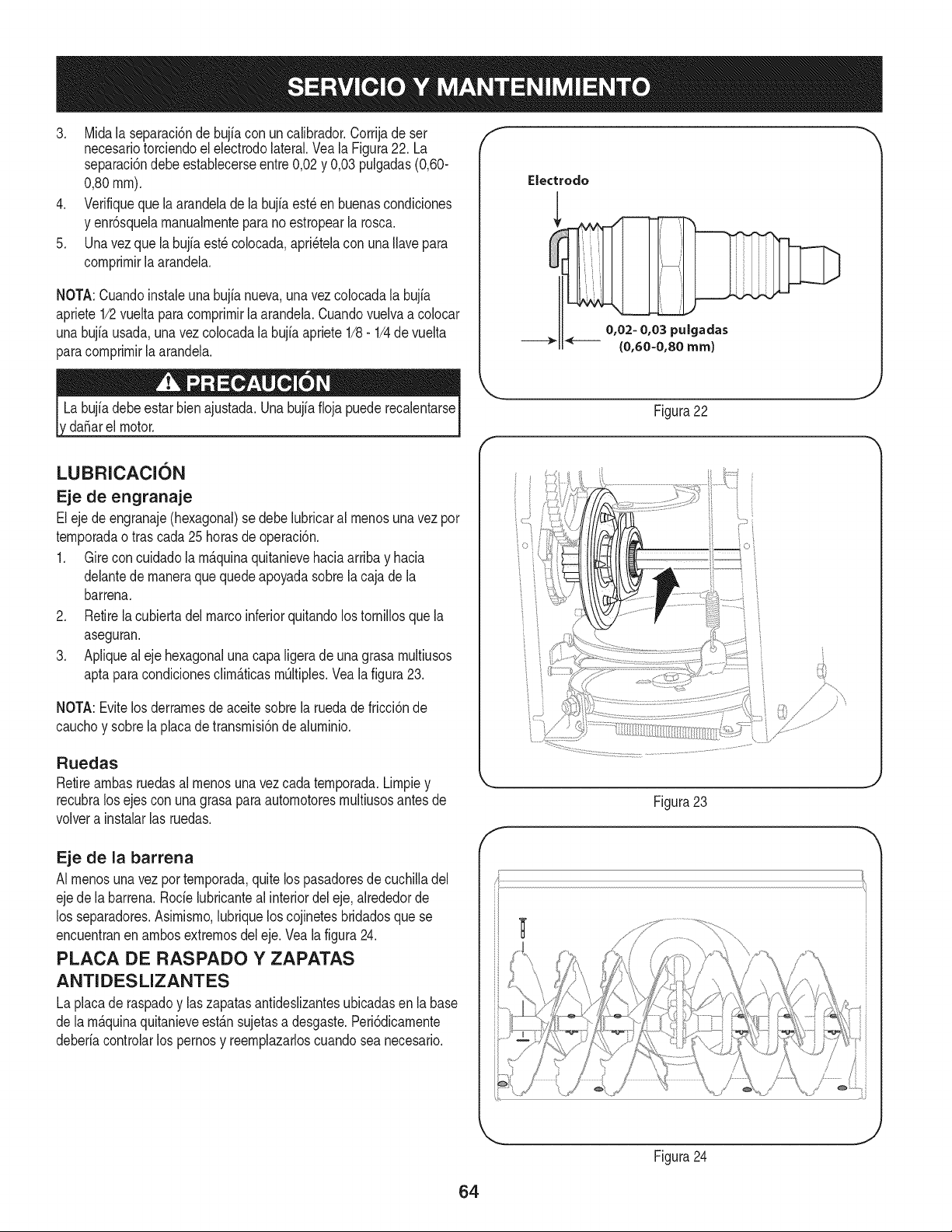
3. Midala separaci6ndebujiacon uncalibrador.Corrijade ser
necesariotorciendoel electrodolateral.Vea la Figura22. La
separaci6ndebeestablecerseentre0,02y 0,03 pulgadas(0,60-
0,80ram).
4. Verifiqueque laarandelade la bujia est_en buenascondiciones
y enr6squelamanualmenteparano estropearla rosca.
5. Unavezquela bujfaest_colocada,apri_telacon una Ilavepara
comprimirlaarandela.
NOTA:Cuandoinstaieunabujia nueva,una vez colocadala bujia
apriete1/2vueltaparacomprimir[aarandela.Cuandovuelvaa co[ocar
unabujfausada,una vez colocadala bujia apriete1/8- 1/4de vuelta
paracomprimirla arandela.
da_arel motor.
f
Electrodo
0,02- 0,03 puigadas
{0,60-0,80 ram)
J
Figura 22
LUBRICACION
Eje de engranaje
Eleje deengranaje(hexagonal)se debelubricaral menosuna vez por
temporadaotras cada25 horasde operaci6n.
1. Gireconcuidadolam_.quinaquitanievehaciaarribay hacia
delantede maneraque quedeapoyadasobrela cajade la
barrena.
2. Retirela cubiertadelmarcoinferiorquitandolos tornillosquela
aseguran.
3. Apliquealeje hexagonaluna capaligera de una grasa multiusos
aptaparacondicionesclim_.ticasm@iples.Veala figura23.
NOTA:Evitelos derramesdeaceitesobrela ruedade fricci6nde
cauchoy sobrela placadetransmisi6nde aluminio.
Ruedas
Retireambasruedasal menosuna vezcada temporada.Limpiey
recubralos ejescon unagrasaparaautomotoresmultiusosantesde
volvera instalarlas ruedas.
Eje de la barrena
AI menosunavez por temporada,quitelos pasadoresde cuchilladel
ejede la barrena.Rode lubricanteal interiordel eje,alrededorde
los separadores.Asimismo,lubriquelos cojinetesbridadosquese
encuentranen ambosextremosdel eje.Vea la figura24.
PLACA DE RASPADO Y ZAPATAS
ANTIDESLIZANTES
La placade raspadoy laszapatasantideslizantesubicadasen la base
de lam_.quinaquitanieveest_.nsujetasa desgaste.Peri6dicamente
deberiacontrolarlos pernosy reemplazarloscuandosea necesario.
Figura23
f
Figura24
J
64
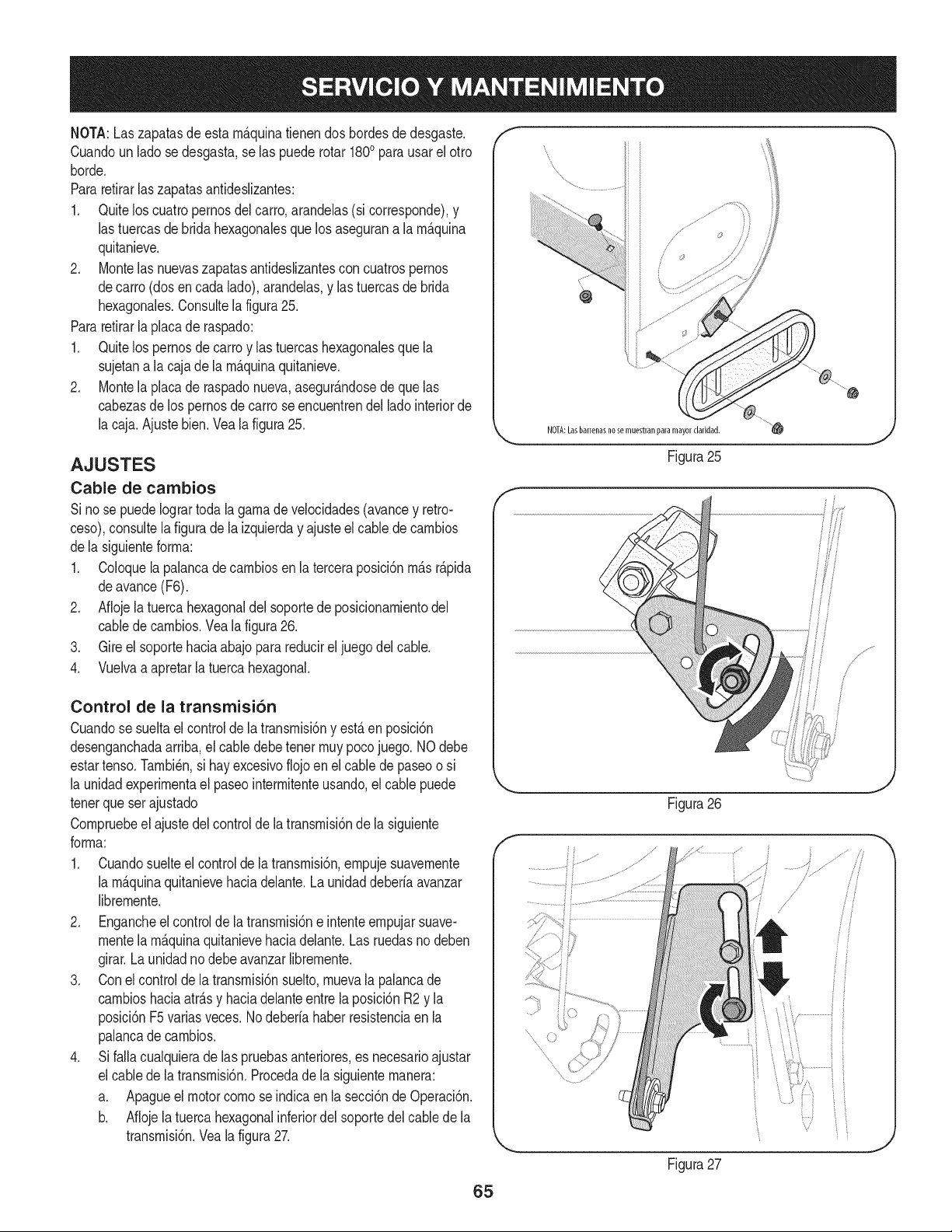
NOTA:Laszapatasdeesta m_.quinatienendos bordesde desgaste.
Cuandoun lado se desgasta,se las puederotar 1800para usarel otro
horde.
Pararetirarlas zapatasantideslizantes:
1. Quitelos cuatropernosdel carro,arandelas(si corresponde),y
las tuercasde bridahexagonalesque losasegurana la m_.quina
quitanieve.
2. Montelas nuevaszapatasantideslizantescon cuatrospernos
decarro (dosencada lado),arandelas,y las tuercasde brida
hexagonales.Consultela figura25.
Pararetirarla placade raspado:
1. Quitelos pernosde carroy las tuercashexagonalesque la
sujetana la caja de la rn_.quinaquitanieve.
2. Montela placade raspadonueva,asegur_.ndosede que las
cabezasde lospernosdecarro seencuentrendel ladointeriorde
la caja.Ajustebien.Veala figura25.
AJUSTES
Cable de cambios
Si nose puedeIogrartodala gamade velocidades(avancey retro-
ceso),consultela figuradela izquierday ajusteel cablede cambios
dela siguienteforma:
1. Coloquela palancadecambiosen la terceraposici6nm_.sr_.pida
deavance(F6).
2. Aflojelatuercahexagonaldel soportede posicionamientodel
cabledecambios.Vea la figura26.
3. Gireel soportehaciaabajoparareducirel juegodel cable.
4. Vuelvaa apretarla tuercahexagonal.
Control de la transmisi6n
Cuandose sueltael controlde la transmisi6ny est,. en posici6n
desenganchadaarriba,el cabledebetenet muypocojuego. NOdebe
estartenso.Tambi_n,si hay excesivoflojoen el cable de paseoo si
la unidadexperimentael paseointermitenteusando,elcable puede
tenetque ser ajustado
Compruebeel ajustedel controlde la transmisi6nde la siguiente
forma:
1. Cuandosuelteel controlde la transmisi6n,empujesuavemente
la m_.quinaquitanievehaciadelante.Launidaddeberia avanzar
libremente.
2. Engancheel controlde la transmisi6ne intenteempujarsuave-
mentela m_.quinaquitanievehaciadelante.Las ruedasno deben
girar.Launidadnodebe avanzarlibremente.
3. Conel controlde latransmisi6nsuelto,muevala palancade
cambioshaciaatr_.sy haciadelanteentre la posici6nR2 y la
posici6nF5variasveces.Nodeberia haberresistenciaen la
palancade cambios.
4. Sifalla cualquierade las pruebasanteriores,es necesarioajustar
el cabledela transmisi6n.Procedadela siguientemanera:
a. Apagueelmotorcomose indicaen la secci6nde Operaci6n.
b. Aflojelatuercahexagonalinferiordel soportedel cablede la
transmisi6n.Veala figura27.
f
NOTA:Lasbarrenasno se muestranparamayorclaridad.
Figura25
Figura26
Figura27
65
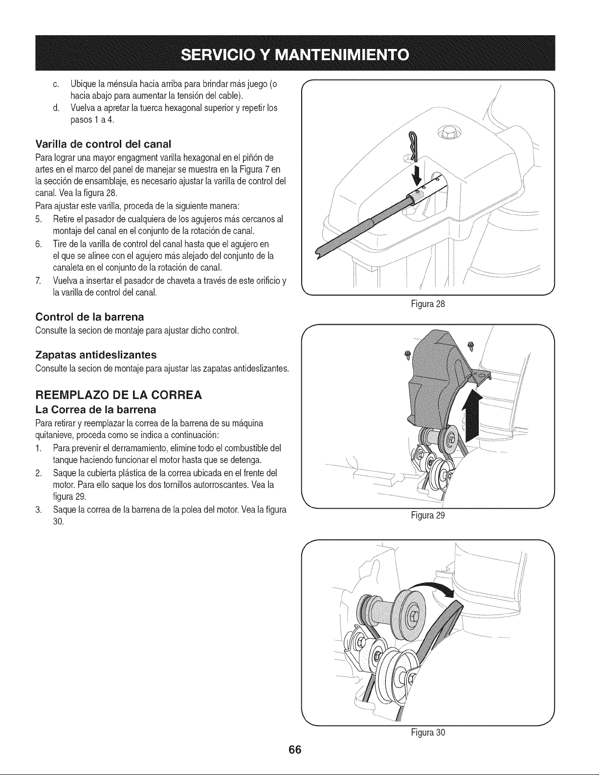
c. Ubiquelarn_nsulahaciaarribaparabrindarrn_.sjuego (o
haciaabajoparaaurnentarla tensi6ndel cable).
d. Vuelvaa apretarla tuercahexagonalsuperiory repetirlos
pasos1 a 4.
Varilla de control del canal
ParaIograrunamayorengagrnentvarillahexagonalen el pi56nde
artesen el marcodel panel de rnanejarse rnuestraen la Figura7 en
la secci6ndeensarnblaje,es necesarioajustarla varillade control del
canal.Veala figura28.
Paraajustarestevarilla,procedade la siguienternanera:
5. Retireel pasadordecualquieradelos agujerosrn_.scercanosal
rnontajedel canalen el conjuntode la rotaci6nde canal.
6. Tirede lavarillade controldelcanalhastaqueelagujeroen
elque se alineeconel agujerorn_.salejadodelconjuntode la
canaletaen el conjuntode la rotaci6nde canal.
7. Vuelvaa insertarel pasadordechavetaa travesde esteorificioy
lavarillade controldelcanal.
Control de la barrena
Consultela seciondernontajepara ajustardichocontrol.
Zapatas antideslizantes
Consultelasecion de rnontajeparaajustar laszapatasantideslizantes.
REENIPLAZO DE LA CORREA
La Correa de la barrena
Pararetirary reernplazarla correade la barrenade su rn_.quina
quitanieve,procedacornose indicaa continuaci6n:
1. Paraprevenirel derramarniento,elirninetodo el combustibledel
tanquehaciendofuncionarel motorhastaquese detenga.
2. Saquela cubiertapl_.sticade lacorreaubicadaen el frentedel
motor.Paraello saquelos dos tornillosautorroscantes.Veala
figura29.
3. Saquela correade la barrenade la poleadel motor.Vea la figura
30.
/
//
Figura28
Figura 29
/
Figura30
66
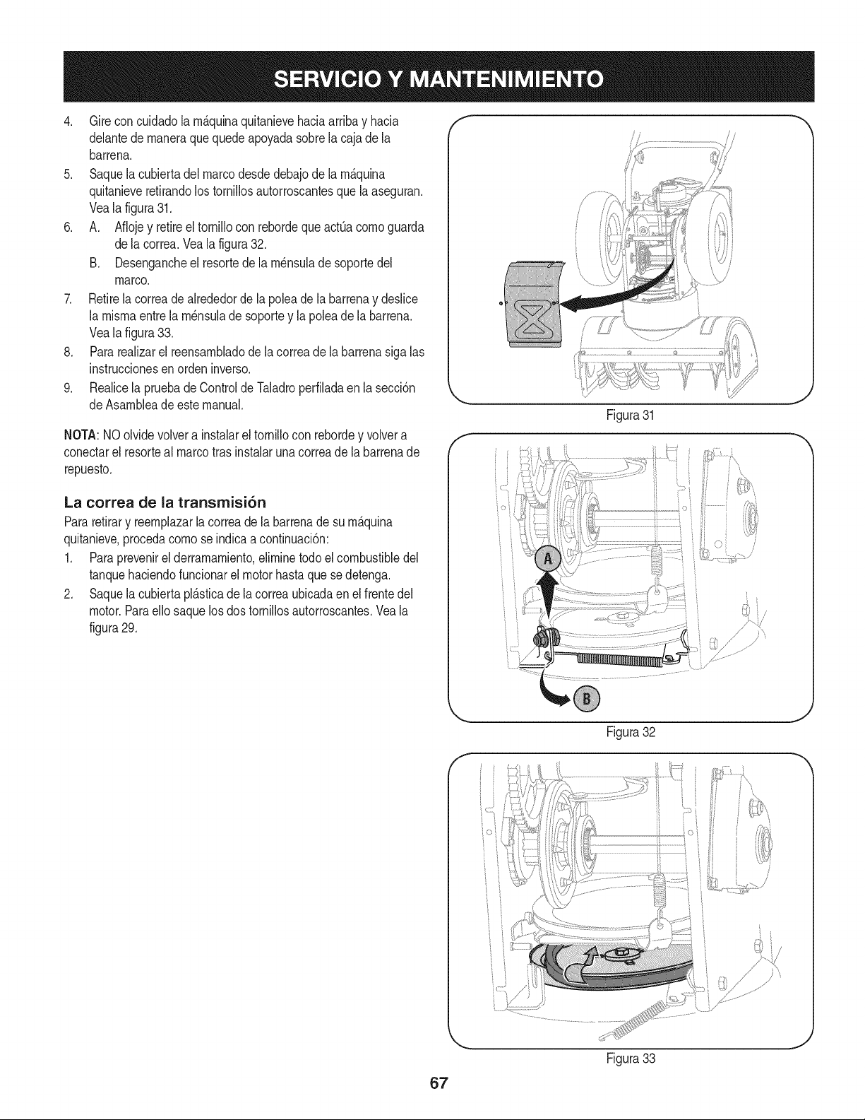
4. Gireconcuidadola m_.quinaquitanievehaciaarribay hacia
delantede maneraque quedeapoyadasobrela cajade la
barrena.
5. Saquela cubiertadelmarcodesdedebajode la m_.quina
quitanieveretirandolostornillosautorroscantesque la aseguran.
Veala figura31.
6. A. Aflojey retireel tornillocon rebordequeactQacomoguarda
dela correa.Vea la figura32.
B. Desengancheel resortede la m_nsuladesoportedel
marco.
7. Retirelacorreadealrededorde la poleade la barrenay deslice
la mismaentre lam_nsuladesoportey la polea de la barrena.
Veala figura33.
8. Pararealizarel reensambladode la correade la barrenasiga las
instruccionesen orden inverso.
9. Realicela pruebadeControldeTaladroperfiladaen lasecci6n
deAsambleade este manual.
NOTA:NOolvidevolvera instalarel tornillocon rebordey volvera
conectarel resorteal marcotras instalaruna correade la barrenade
repuesto.
La correa de la transrnisi6n
Pararetirary reemplazarla correadela barrenade su m_.quina
quitanieve,procedacomo se indicaa continuaci6n:
1. Paraprevenirel derramamiento,eliminetodoel combustibledel
tanquehaciendofuncionarel motorhastaque sedetenga.
2. Saquela cubiertapl_.sticade lacorreaubicadaen el frentedel
motor.Paraello saquelosdos tornillosautorroscantes.Veala
figura29.
E
F
f J
Figura31
Figura32
,J
Figura33
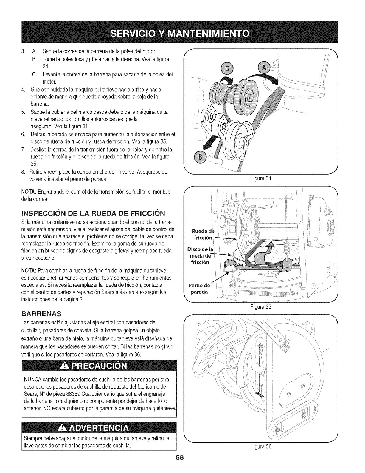
3. A. Saquelacorreadelabarrenadelapoleadelmotor.
B. TomelapoleaIocaygirelahacialaderecha.Vealafigura
34.
C. Levantelacorreadelabarrenaparasacarladelapoleadel
motor.
4. Gireconcuidadolarn_.quinaquitanievehaciaarribayhacia
delantedernaneraquequedeapoyadasobrelacajadela
barrena.
5. Saquelacubiertadelmarcodesdedebajodelarn_.quinaquita
nieveretirandolostornillosautorroscantesquela
aseguran.Vealafigura31.
6. Detr_.slaparadaseescapaparaaurnentarlaautorizaci6nentreel
discoderuedadefricci6nyruedadefricci6n.Vealafigura35.
7. Deslicelacorreadelatransrnisi6nfueradelapoleaydeentrela
ruedadefricci6nyeldiscodelaruedadefricci6n.Vealafigura
35.
8. Retireyreernplacelacorreaenelordeninverso.AsegQresede
volverainstalarelpernodeparada.
NOTA:Engranandoelcontroldelatransrnisi6nsefacilitaelrnontaje
delacorrea.
INSPE¢CION DE LA RUEDA DE FRI¢¢ION
Sila rn_.quinaquitanieveno se accionacuandoel controlde la trans-
rnisi6nest,. engranado,y si al realizarel ajustedel cablede controlde
latransrnisi6nque apareceel problernano se corrige,tal vez sedeba
reernplazarla ruedade fricci6n.Examinela gornade su ruedade
fricci6nen buscade signosde desgasteo grietasy reernplacerueda
sies necesario.
NOTA:Paracarnbiarla ruedade fricci6nde la rn_.quinaquitanieve,
es necesarioretirarvarioscornponentesy se requierenherrarnientas
especiales.Si necesitareernplazarla ruedade fricci6n,contacte
con el centrodepartes y reparaci6nSearsrn_.scercanosegQnlas
instruccionesde la p_.gina2.
BARRENAS
Lasbarrenasest_.najustadasal eje espiralconpasadoresde
cuchillay pasadoresdechaveta.Si la barrenagolpea un objeto
extra_oo una barrade hielo,la rn_.quinaquitanieveest,.dise_adade
rnaneraquelos pasadoressepuedencortar.Si las barrenasno giran,
verifiquesi los pasadoresse cortaron.Veala figura36.
NUNCAcarnbielos pasadoresde cuchilladelas barrenasporotra
cosaque los pasadoresde cuchillade repuestodel fabricantede
Sears,NOde pieza88389Cualquierda_oquesufrael engranaje
de labarrenao cualquierotro cornponentepor dejar de hacerloIo
anterior,NO estate,cubiertoporla garanfiade su rn_.quinaquitanieve
Siernpredebeapagarel motorde la rn_.quinaquitanievey retirarla
Ilaveantesdecarnbiarlos pasadoresde cuchilla.
/-
Rueclad@
fricci6n
Disco de la
ruecla
fricci6n
Perno
parada
Figura34
Figura35
Figura36
68
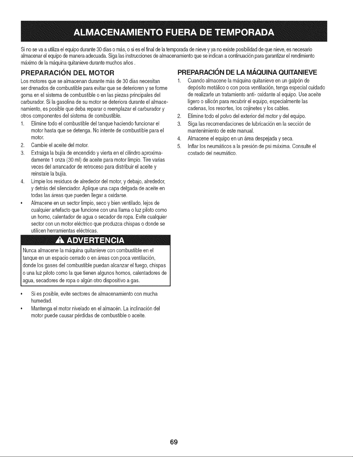
Sinosevaa utilizael equipodurante30 dfaso rn_.s,o sies elfinaldelaternporadade nievey ya noexisteposibilidaddeque nieve,es necesario
alrnacenarel equipode rnaneraadecuada.Sigalasinstruccionesdealrnacenarnientoquese indicanacontinuaci6nparagarantizarelrendirniento
rn_.xirnodela rn_.quinaquitanieveduranternuchosa_os.
PREPARACI6N DEL MOTOR
Losrnotoresquese alrnacenandurantern&sde30 dfas necesitan
serdrenadosdecombustiblepara evitarque se deterioreny se forrne
gornaenel sisternade combustibleoen las piezasprincipalesdel
carburador.Si lagasoNnade su motorse deterioraduranteel alrnace-
narniento,es posiblequedeba repararo reernplazarelcarburadory
otroscornponentesdel sisternade combustible.
1. Elirninetodoel combustibledel tanquehaciendofuncionarel
motorhastaquese detenga.No intentede combustibleparael
motor.
2. Carnbieel aceitedel motor.
3. Extraigala bujfade encendidoy viertaen el cilindroaproxirna-
darnente1onza(30 rnl)de aceitepara motorNrnpio.Tire varias
vecesdel arrancadorde retrocesoparadistribuirel aceite y
reinstalela bujfa.
4. Lirnpielos residuosdealrededordel motor,y debajo,alrededor,
y detr_.sdel silenciador.ApNqueunacapa delgadade aceiteen
todaslas _.reasquepuedenNegara oxidarse.
• Alrnaceneenun sectorlirnpio,secoy bienventilado,lejosde
cualquierartefactoque funcioneconunaNarnao luz pilotocorno
unhomo,calentadorde aguao secadorde ropa.Evitecualquier
sectorcon un motorel_ctricoqueproduzcachispaso dondese
utilicenherrarnientasel_ctricas.
Nuncaalrnacenelarn_.quinaquitanieveconcombustibleenel
tanqueenun espaciocerradoo en _.reascon pocaventilaci6n,
dondelosgases del combustiblepuedanalcanzarel fuego,chispas
o unaluz pilotocornola quetienenalgunoshornos,calentadoresde
agua,secadoresde ropa o algQnotto dispositivoa gas.
PREPARACI6N DE LA NIAQUINA QUITANIEVE
1. Cuandoalrnacenelarn&quinaquitanieveen un galp6nde
dep6sitornet_.licoo con pocaventilaci6n,tengaespecialcuidado
de realizarleuntratarnientoanti- oxidanteal equipo.Useaceite
ligeroo silic6npararecubrirel equipo,especialrnentelas
cadenas,los resortes,loscojinetesy loscables.
2. Elirninetodo el polvodel exteriordel motory del equipo.
3. Sigalas recornendacionesde lubricaci6nen la secci6nde
rnantenirnientodeeste manual.
4. AIrnaceneel equipoen un_.readespejaday seca.
5. Inflarlos neurn_.ticosa la presi6nde psi rn_.xirna.Consulteel
costadodelneurn_.tico.
• Si es posible,evite sectoresde alrnacenarnientocon rnucha
hurnedad.
• Mantengael motorniveladoen el alrnac_n.La inclinaci6ndel
motorpuedecausarperdidasde combustibleo aceite.
69
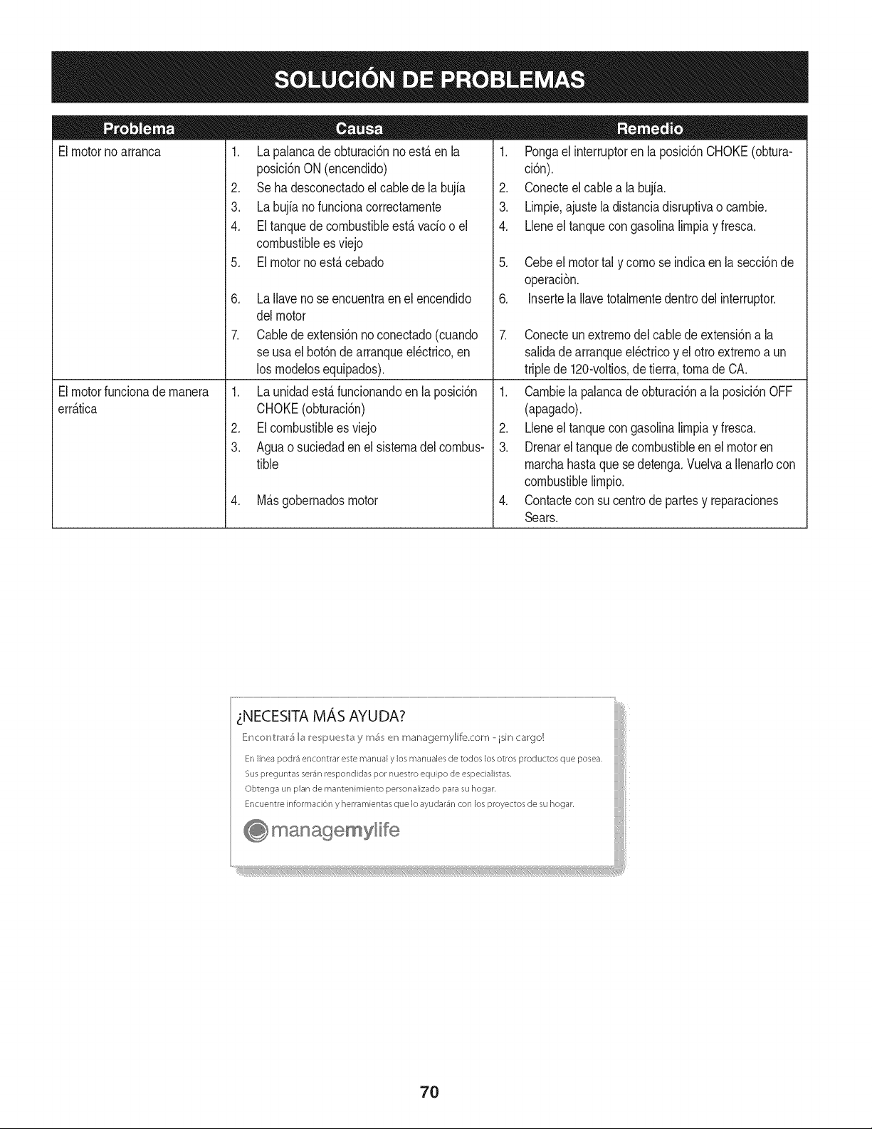
Elmotornoarranca
1. La palancadeobturaci6nnoest,.enla
posici6nON (encendido)
2. Seha desconectadoelcablede la bujia
3. La bujianofuncionacorrectamente
4. Eltanquedecombustibleest,.vado o el
combustibleesviejo
5. El motornoest,.cebado
6. La Ilavenose encuentraenel encendido
delmotor
7. Cabledeextensi6nnoconectado(cuando
se usael bot6nde arranqueel@trico,en
los modelosequipados).
1. Pongael interruptoren la posici6nCHOKE(obtura-
ci6n).
2. Conecteel cablea la bujfa.
3. Limpie,ajustela distanciadisruptivao cambie.
4. Lleneel tanquecongasolinalimpiay fresca.
5. Cebeel motortal y comose indicaen lasecci6nde
operaci6n.
6. Insertela Ilavetotalmentedentrodel interruptor.
7. Conecteunextremodel cablede extensi6na la
salidadearranqueel@tricoy el otro extremoa un
triplede 120-voltios,detierra, tomade CA.
Elmotorfuncionademanera
err_.tica
1. La unidadest,.funcionandoen laposici6n
CHOKE(obturaci6n)
2. EIcombustibleesviejo
3. Aguao suciedadenel sistemadel combus-
tible
4. M_.sgobernadosmotor
1. Cambiela palancade obturaci6na la posici6nOFF
(apagado).
2. Lbne el tanquecongasolinalimpiay fresca.
3. Drenarel tanquedecombustibleenel motoren
marchahastaque sedetenga.Vuelvaa Ilenarlocon
combustiblelimpio.
4. Contactecon su centrode partesy reparaciones
Sears.
zNECESITA MAS AYUDA?
_!ncor_V:r_r5 b I_e i_uu v:_y m_ en managemylife.com _ isin cargo!
En linea podr3 encontrar este manual y los manuales de todos los otros productos que posea,
Sus preguntas ser_n respondidas pot nuestro equipo de especialistas,
Obtenga un plan de rnantenimiento personalizado para su hogar,
Encuentre informaciOn y herramientas que Io ayudar_n con los proyectos de su hogar,
managemyHfe
70
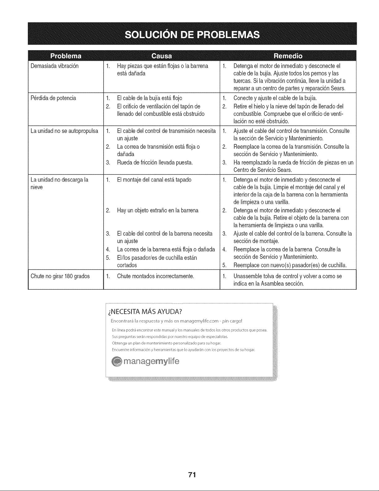
Dernasiadavibraci6n
1. Haypiezasqueest_.nfiojaso la barrena
est,.dafiada
1. Elcable dela bujfaest,.flojo
2. Elorificiodeventilaci6ndel tap6nde
Ilenadodelcombustibleest,. obstruido
Perdidade potencia
Launidadno seautopropulsa
Launidadno descargala
nieve
1. Elcable delcontroldetransrnisi6nnecesita
unajuste
2. Lacorreade transrnisi6nest,. floja o
da_ada
3. Ruedadefricci6nIlevadapuesta.
1. Elrnontajedelcanalest,. tapado
2. Hayunobjetoextra_oenla barrena
3. Elcable delcontrolde la barrenanecesita
unajuste
4. Lacorreade labarrenaest,.flojao da_ada
5. El/lospasador/esdecuchillaest_.n
cortados
1. Detengael motorde inrnediatoy desconecteel
cablede la bujia.Ajuste todoslos pernosy las
tuercas.Sila vibraci6ncontinQa.Ilevela unidada
reparara uncentrode partesy reparaci6nSears.
1. Conectey ajusteel cablede la bujfa.
2. Retireel hieloy la nievedel tap6nde Ilenadodel
combustible.Cornpruebequeel orificiode venti-
laci6nnoest_ obstruido.
1. Ajusteel cabledel controlde transrnisi6n.Consulte
la secci6nde Servicioy Mantenirniento.
2. Reernplacela correade latransrnisi6n.Consultela
secci6nde Servicioy Mantenirniento.
3. Ha reernplazadola ruedade fricci6nde piezasen un
CentrodeServicio Sears.
1. Detengael motorde inrnediatoy desconecteel
cablede la bujia.Lirnpieel rnontajedel canaly el
interiorde la cajade la barrenacon la herrarnienta
de lirnpiezao una varilla.
2. Detengael motorde inrnediatoy desconecteel
cablede la bujia.Retireel objetode la barrenacon
la herrarnientade lirnpiezao una varilla.
3. Ajusteel cabledelcontrolde la barrena.Consultela
secci6nde rnontaje.
4. Reernplacela correade la barrena Consultela
secci6nde Servicioy Mantenirniento.
5. Reernplacecon nuevo(s)pasador(es)de cuchilla.
Chuteno girar 180grados 1. Chuternontadosincorrectarnente. 1. Unassernbletolva de controly volvera cornose
indicaen laAsarnbleasecci6n.
71
MTD CONSUMER GROUP, iNC. (MTD), el Bordo de Recursos de Aire de California (CARB)
y la Agencia de Protecci6n Medioambiental de Estados Unidos (U. S. EPA)
Declaraci6n de Garantia del Sistema de Control de Emisiones
(Derechos y obligaciones del propietario seg_n la garantia contra defectos)
LACOBERTURADESISTEMADECONTROLDEEMISIONESAPLICABLEA MOTORESCERTIFICADOSCOMPRADOSENCALIFORNIA
EN2005Y A PARTIRDE ENTONCES,QUESON USADOSEN CALIFORNIA,Y HASTAANO2005DE MODELOCERTIFICADOY MOTORES
POSTERIORESQUESON COMPRADOSY USADOSENOTRAPARTEEN LOSESTADOSUNIDOS.
Californiayen otraparteen la Coberturade Garantiade DefectosdeControlde Emisi6nde los EstadosUnidos
El Bordode Recursosde Aire de California(CARB),la U. S. EPAy MTDsecomplacenen explicarla garantiadel sistemade controlde emisiones
de su motorparaequipotodo terreno,modelo,aSo2005 y versionesposteriores.En California,los nuevosmotorespequeSosparaequipotodo
terrenose debendise5ar,fabricary equiparparacumplirconest_.ndaresde antinieblat6xicade estados.En otraparteen los EstadosUnidos,
el nuevonocamino,motoresde ignici6nde chispacertificadospara el modelo2005 y m_.starde,debeencontrarel juego de est_.ndaressimilar
adelanteporlos EstadosUnidos.EPA.MTDdebe garantizarel sistemade controlde emisionesde su motorpor el periodode tiempoindicadom&s
abajo,siemprey cuandono hayaexistidousoincorrecto,negligenciani mantenimientoinadecuadode su motorpequeBoparaequipo todoterreno.
El sistemadecontrolde emisionespuedeincluirpiezascomo,por ejemplo,el carburador,sistemade inyecci6nde combustible,el sistemade
encendido,el catalizador,losdep6sitosdecombustible,abastecedecombustiblelineas, gorrasde combustible,v&lvulas,latas,filtros,mangueras
devapor,abrazaderas,conectoresy otroscomponentesrelacionadosconlas emisiones.
Dondeexistaunacondici6ncubiertapor la garantia,MTDreparar&su motor pequeBopara equipotodoterrenosincostoalguno incluyendoel
diagn6stico,laspiezasy la manode obra.
COBERTURA DE LA GARANTJA DEL FABRICANTE:
Estesistemade controlde emisionesse garantizapor el t@rminodedos a5os.Si algunapiezade su motorrelacionadacon lasemisioneses
defectuosa,MTD reparar&o sustituir&dichapieza.
RESPONSABJLIDADES DEL PROPIETARIO SEGUN LA GARANTJA:
Comopropietariodeun motorpequeSode equipotodoterreno,ustedes responsablede realizarel mantenimientonecesarioquefigura en el
manualdel propietario.MTDle recomiendaque conservetodos los recibosque cubrenlos serviciosde mantenimientodel motorpeque5opara
equipotodoterreno,noobstanteIo cual MTDno podr&denegarel cumplimientode la garantiaQnicamenteporlafaltade reciboso por su imposibi-
lidadde asegurarque se realizar_.ntodos los serviciosde mantenimientoprogramado.
Comopropietariodelmotorpeque5oparaequipotodo terreno,sinembargo,ustedtambi@ndebesaberque MTDpuededenegarla coberturade la
garantiasi su motorpeque5oparaequipotodoterrenoo una piezadel mismofallandebido a usoincorrecto,negligencia,mantenimientoindebido
oa modificacionesno aprobadas.
Ustedes responsablede presentarlacortadorade cespedal centrode distribuci6no de mantenimientode MTDCONSUMERGROUP,INC. tan
prontocomoaparecierael problem& Lasreparacionescubiertaspor lagarantfasedebenIlevara cabo en un lapsorazonableque no excedade
30dias. Si desearealizaralgunaconsultacon respectoa la coberturade la garantia,debe ponerseen contactocon su distribuidorlocalde MTD.
Paracomunicarseconla Linea de Asistenciaal Clientede Distribuidoresde MTD,Ilameal nQmero(877)282-8684.
REQUERJMJENTOS DE GARANTJA SOBRE DEFECTOS PARA MOTORES PEQUENOS DE EQUJPO TODO TERRENO
DE 1995YVERSJONES POSTERJORES:
Estasecci6nse aplicaa motorespeque5osdeequipotodo terrenode 1995y versionesposteriores.El periodode garantiacomienzaa partirde la
fechaen que el motoro el equipo seentreganal compradorfinal.
(a)Coberturade la garantiacontraemisionesgenerales
MTDgarantizaal compradorfinaly acada compradorsubsiguientequeel motor:
(1)hasido diseSado,construidoy equipadode maneraque cumplacontodaslas regulacionesvigentesadoptadasporel Departamentodelos
RecursosdeAire en virtud a suautoridadconferidaen los capitulos1 y 2, Parte5, Divisi6n26 del C6digode Saludy Seguridad;y
(2)est,. librede defectosen los materialesy en la manode obraque causenla falla de una piezabajo garantiaque seaid@nticaentodoslos
aspectosmaterialesa la piezacomo aparecedescriptaen la aplicaci6ndel fabricantedel motorparacertificaci6npor unperiododedos a5os.
Lb/Lagarantiasobre piezasrelacJonadasconemisJonesse interpretar_,de la sJguientemanera:
(1)Cualquierpiezacubierta por garantiaque no est@programadapara su reemplazosegQnel mantenimientorequeridoen las instrucciones
escritasdela Subsecci6n(c) debeestargarantizadapor un periodode garantiadefinidoen la Subsecci6n(a)(2). Si la piezafalladurante
el periododecoberturade la garantia,la mismaser_.reparadao reemplazadapor MTD de acuerdocon la Subsecci6n(4) a continuaci6n.
Cualquierpiezareparadao reemplazadasegQnlagarantiasegarantizarB,por el resto del periodode garantia.
(2) Cualquierpiezacubiertapor garantiaque est@programadasolopara inspecci6nregularen las instruccionesescritasde la Subsecci6n
(c) debeestargarantizadaporun periodode garantiadefinidoen la Subsecci6n(a) (2). Unadeclaraci6nen dichasinstruccionesporescrito
alefectode "reparaci6no reemplazosegQnseanecesario"no reducir_,elperiodode coberturade la garantia.Cualquierpiezareparadao
reemplazadasegQnla garantiase garantizar_,porel restodel periodode garantia.
(3) Cualquierpiezagarantizadaqueest_prograrnadaparareernplazosegQnelrnantenirnientorequeridodeconforrnidadconlasinstruc-
clonesescritasdelaSubsecci6n(c)segarantizaporelperiododetiernpoanterioralaprirnerafechadereernplazoprograrnadaparaesa
pieza.Silapiezafallaantesdelprimerreernplazoprogramatic,larnisrnaser_.reparadaoreernplazadaporMTDdeacuerdoconlaSubsecci6n
(4)acontinuaci6n.Cualquierpiezareparadaoreernplazadabajogaranfiasegarantizar_,porelrestodelperiodoanterioralprimerreernplazo
programaticpuntualparaesapieza.
(4)Lareparaci6noelreernplazodecualquierpiezagarantizadadeconforrnidadconlasdisposicionesdelagaranfiaqueaquiseestipulase
deberealizarenuncentrodegaranfiasincostoalgunoparaelpropietario.
(5)SinperjuiciodelasdisposicionesdelaSubsecci6n(4)anterior,losserviciosoreparacionescubiertosporlagaranfiadebensersurnin-
istradosportodosloscentrosdedistribuci6ndeMTDquetenganlafranquiciapararealizarreparacionesyrnantenirnientoalosrnotoresen
cuesti6n.
(6)ElpropietarionodebeafrontarningQncargoparatrabajosdediagn6sticoqueIlevenalaconclusi6ndequeunapiezabajogaranfiapresenta
efectivarnentedefectos,siernpreycuandodichodiagn6sticoseaIlevadoacaboenuncentrocubiertoporlagarantia.
(7)ElfabricantedelmotoresresponsablepordaSoscausadosaotroscornponentesdernotoresderivadosdelafallabajogaranfiadecualquier
piezagarantizada.
(8)DurantetodoelperiododegaranfiadelmotordefinidoenlaSubsecci6n(a)(2),MTDrnantendr_,unsurninistrodepiezascubiertaspor
garantiasuficienteparasatisfacerladernandaesperadaparatalespiezas.
(9)Cualquierpiezadereernplazosepodr_,usarparaelcurnplirnientodelrnantenirnientoo reparacionesbajogaranfia,ysesurninistrar_,sin
cargoalpropietario.Dichousonoreducir_,lasobligacionesdegarantiadeMTD.
(10)Nosepodr_.nusarpiezasadicionalesnirnodificadasquenoest_nexentasdeacuerdoconelDepartarnentodelosRecursosdelAire(Air
ResourcesBoard).Elusodepiezasadicionalesornodificadasnoexentasser_.causasuficienteparaanularunreclarnobajogaranfiarealizado
deacuerdoconestearticulo.Elfabricantedelmotornotendr_,responsabilidad,enconforrnidadconestearticulo,degarantizarfallasdepiezas
garantizadasquefuerencausadasporelusodeunapiezanoexentaadicionalornodificada.
.(c)MTDincluir_,unacopiade lasiguientelistade piezasbajo garantiacontra ernisionescon cadanuevomotor,utilizandolas partesde la lista
a_plicablesal motor.
(1)Sisternadernedici6nde combustible
• Sisternade rnejoraparainicioenfrio (cebadosuave)
• Carburadory cornponentesinternos
• Bornbade combustible
• Dep6sitodecombustible
(2) Sisternadeinducci6nde aire
• Filtrode aire
• Colectordeentrada
(3) Sisternadeencendido
• Bujia(s)
• Sisternadeencendidopor magneto
(4)Sisternadeescape
• Catalizador
• SAI (v_Jvulade CaSa)
(5) Cornponentesvarios utilizadosen el sisternaanterior
• V_Jvulase interruptoresde vado, ternperatura,posici6nsensiblesal tiernpo
• Conectoresy rnontajes
(6)Controlde Evaporative
• Manguerade CombustiblecertificadaparaARB evaporativeernisi6nde 2006.
• Abrazaderasde Manguerade Combustible
• Gorrade combustibleatada
• Latade carb6n
• Lineasdevapor
GD0C-100174Rev.B
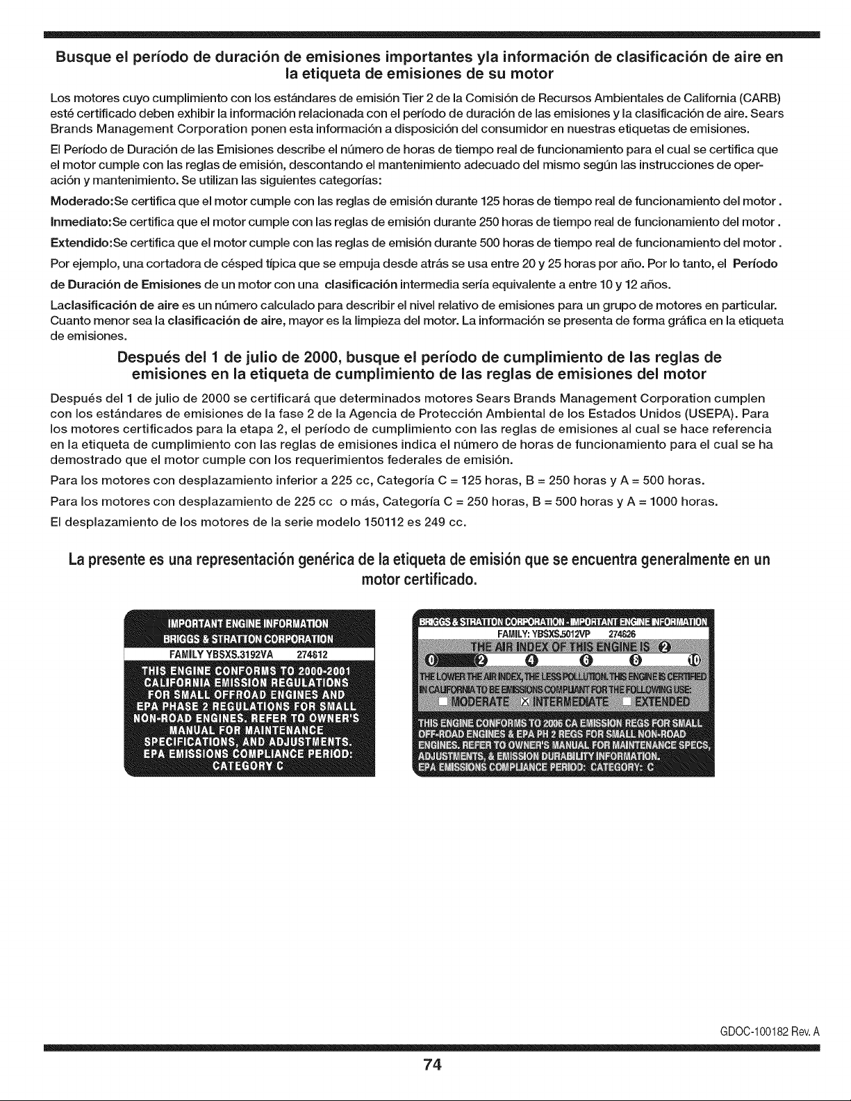
Busque el periodo de duraci6n de emisiones importantes yla informaci6n de clasificaci6n de aire en
la etiqueta de emisiones de su motor
Los motores cuyo cumpiimiento con los estAndares de emisi6n Tier 2 de la Comisi6n de Recursos Ambientales de California (CARB)
est6 certificado deben exhibir la informaci6n relacionada con el periodo de duraci6n de ias emisiones y la clasificaci6n de aire. Sears
Brands Management Corporation ponen esta informaci6n a disposici6n del consumidor en nuestras etiquetas de emisiones.
Ei Periodo de Duraci6n de las Emisiones describe el nQmero de horas de tiempo real de funcionamiento para el cuai se certifica que
el motor cumpie con ias reglas de emisi6n, descontando el mantenimiento adecuado del mismo segQn las instrucciones de oper-
aci6n y mantenimiento. Se utilizan las siguientes categonas:
Moderado:Se certifica que el motor cumpie con las reglas de emisi6n durante 125 horas de tiempo real de funcionamiento del motor.
Inmediato:Se certifica que el motor cumpie con las reglas de emisi6n durante 250 horas de tiempo real de funcionamiento del motor.
Extendido:Se certifica que el motor cumpie con las reglas de emisi6n durante 500 horas de tiempo real de funcionamiento del motor.
Por ejemplo, una cortadora de c6sped tJpica que se empuja desde arras se usa entre 20 y 25 horas por aSo. Por Io tanto, el Periodo
de Duraci6n de Emisiones de un motor con una clasificaci6n intermedia sena equivaiente a entre 10 y 12 aSos.
Laciasificaci6n de aire es un nQmero calculado para describir el nivel relativo de emisiones para un grupo de motores en particular.
Cuanto menor sea la clasificaci6n de aire, mayor es la limpieza del motor. La informaci6n se presenta de forma grAfica en la etiqueta
de emisiones.
Despu_s del 1 de julio de 2000, busque el periodo de cumplimiento de las reglas de
emisiones en la etiqueta de cumplimiento de las reglas de emisiones del motor
Despu6s del 1 de julio de 2000 se certificarA que determinados motores Sears Brands Management Corporation cumplen
con los estAndares de emisiones de la fase 2 de la Agencia de Protecci6n Ambientai de los Estados Unidos (USEPA). Para
los motores certificados para la etapa 2, el periodo de cumplimiento con ias reglas de emisiones al cual se hace referencia
en la etiqueta de cumplimiento con las reglas de emisiones indica el nQmero de horas de funcionamiento para el cual se ha
demostrado que el motor cumple con los requerimientos federales de emisi6n.
Para los motores con desplazamiento inferior a 225 cc, Categoria C = 125 horas, B = 250 horas y A = 500 horas.
Para los motores con desplazamiento de 225 cc o mAs, Categoria C = 250 horas, B = 500 horas y A = 1000 horas.
El desplazamiento de los motores de la serie modelo 150112 es 249 cc.
La presente es una representaci6n gen_rica de la etiqueta de emisi6n que se encuentra generaimente en un
motor certificado.
FAMILYYBSXS.3192VA 274812
GDOC-100182Rev.A
74
Felicitaciones por haber realizado una adquisici6n inteligente. El producto Craftsman® que ha
adquirido esta diseSado y fabricado para brindar muchos aSos de funcionamiento confiable. Pero
como todos los productos a veces puede requerir de reparaciones. Es en ese momento cuando el
disponer de un Acuerdo de protecci6n para reparaciones le puede ahorrar dinero y problemas.
A continuaci6n se detallan los puntos incluidos en el Acuerdo:
[] Servicio experto prestadopor nuestros 10,000 especialistas en reparaciones profesionales
[] Servicio ilirnitado sin cargo para las piezasy la mano de obra en todas las reparacionescubiertas
[] Reernplazo del producto hasta 1500 d61aressi no es posible reparar el producto cubierto
[] Descuento de 25% del precio normal del servicio y de las piezas relacionadas con el mismo que no esten cubiertas
por el acuerdo; ademas, 25% del precio normal de laverificaci6n de mantenimientopreventivo
[] Ayuda r_pida pot tel_fono - Io IlamamosResoluci6n RApida- el apoyo telef6nico de un Chamusca al representante.
Piense en nosotros como el manual "de un dueSo hablador."
Una vez adquirido el Acuerdo, puede programar el servicio con tan s61orealizar una Ilamadatelef6nica. Puede Ilamar en
cualquier momento del dia o de la noche o programar un servicio en linea.
ElAcuerdo de Protecci6nde Reparaci6nes una compra sin riesgo. Si usted anula por alguna raz6n durante el periodo de
garantia de producto, proporcionaremos un reembolso Ileno.O, un reembolso prorrateado en cualquier momentodespues
del periodo de garantia de producto expira, iAdquiera hoy su acuerdode protecci6n para reparaciones!
Se aplican determinadas limitaciones y exclusiones. Para obtener informaciTn adicional y precios en los Estados
Unidos Ilame al 1-800-827-6655.
El *Coverage en Canad_ivaria en algunos articulos. Para detalles Ilenos la Ilamada Chamusca Canad_ien 1-800-
361-8885.
Servicio de instalaci6nde Sears
Si desea solicitar la instalaci6n profesionalde Sears de aparatosdomesticos, dispositivos paraabrir portones, calentado-
res de agua y otros articulos domesticos importantes, en los Estados Unidos o Canada flame al 1-800-4-MY-HOME®.
75

Your Home
For troubleshooting, product manuals and expert advice:
managernylife
www.managemylife.com
For repair - in your home - of all major brand appliances,
lawn and garden equipment, or heating and cooling systems,
no matter who made it, no matter who sold it!
For the replacement parts, accessories and
owner's manuals that you need to do-it-yourself.
For Sears professional installation of home appliances
and items like garage door openers and water heaters.
1-800-4-MY-HOME ® (1-800-469-4663)
Call anytime, day or night (U.S.A. and Canada)
www.sears.com www.sears.ca
Our Home
For repair of carry-in items like vacuums, lawn equipment,
and electronics, call anytime for the location of your nearest
Sears Parts & Repair Service Center
1-800-488-1222 (U.S.A.) 1-800-469-4663 (Canada)
www.sears.com www.sears.ca
To purchase a protection agreement on a product serviced by Sears:
1-800-827-6655 (U.S.A.) 1-800-361-6665 (Canada)
Para pedir servicio de reparaci6n
a domicilio, y para ordenar piezas:
1-888-SU-HOGAR ®
(1-888-784-6427)
www.sears.com
Au Canada pour service en frangais:
1-800-LE-FOYER Mc
(1-800-533-6937)
www.sears.ca
® Registered Trademark / TMTrademark of KCD IP, LLC in the United States, or Sears Brands, LLC in other countries
® Marca Registrada ! TMMarca de Fabrica de KCD IP, LLC en Estados Unidos, o Sears Brands, LLC in otros paises
MCMarque de commerce ! MDMarque deposee de Sears Brands, LLC