Operator's Manual
P R 0 F E S S I 0 N A
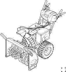
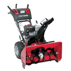
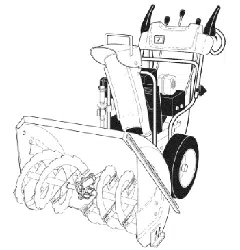
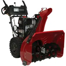
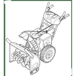
30" SNOW THROWER
Model No. 247.88830
CAUTION: Before using
this product, read this
manual and follow all
safety rules and operating
instructions.
o SAFETY
ASSEMBLY
OPERATION
MAINTENANCE
PARTS LIST
o ESPANOL
Sears Brands Management Corporation, Hoffman Estates, IL 60179, U.S.A.
Visit our website: www.craftsman.com FORM1/0.769-05137C
8/06/2010
WarrantyStatement.................... Page2
SafeOperationPractices.............. Pages3-6
SafetyLabels......................... Page7
Assembly......................... Pages8-13
Operation........................ Pages14-17
Service&Maintenance.............. Pages18-23
Off-SeasonStorage................... Page24
Troubleshooting...................... Page25
PartsList......................... Pages26-36
RepairProtectionAgreement............ Page41
Espa_ol............................. Page42
ServiceNumbers................... BackPage
CRAFTSMANPROFESSIONAL TWO YEAR FULL WARRANTY
FORTWOYEARSfromthe dateof purchase,this productis warrantedagainstanydefectsin materialor workmanship.Defectiveproductwill
receivefree repairor free replacementif repairis unavailable.
Thiswarrantyappliesfor onlyone yearfromthe dateof purchaseif this productis everusedwhileprovidingcommercialservicesor if rentedto
anotherperson.
For warranty coverage details to obtain repair or replacement,visit the web site: www.craftsman.com
This warranty covers ONLYdefects in material and workmanship. Warranty coverage does not include:
• Expendableitemsthatcan wearoutfrom normalusewithin thewarrantyperiod,includingbut not limitedto augers,augerpaddies,drift
cutters,skidshoes,shaveplate,shearpins, spark plug,air cleaner,belts,andoil filter.
• Standardmaintenanceservicing,oilchanges,or tune-ups.
Tire replacementor repaircausedby puncturesfromoutsideobjects,suchas nails,thorns,stumps,or glass.
Tireor wheelreplacementor repairresultingfromnormalwear,accident,orimproperoperationor maintenance.
Repairsnecessarybecauseof operatorabuse, includingbutnot limitedto damagecausedby over-speedingthe engine,or from impacting
objectsthat bendthe frame,augershaft,etc.
• Repairsnecessarybecauseof operatornegligence,includingbut not limitedto, electricalandmechanicaldamagecausedby improper
storage,failureto usethe propergradeandamountof engineoil, or failureto maintainthe equipmentaccordingto the instructionscontained
inthe operator'smanual.
• Engine(fuelsystem)cleaningor repairscausedbyfuel determinedto becontaminatedoroxidized(stale).in general,fuel shouldbeused
within30 daysof itspurchasedate.
Normaldeteriorationandwearof the exteriorfinishes,or productlabelreplacement.
Thiswarrantygivesyou specificlegalrights,andyou mayalso haveotherrightswhichvaryfromstateto state.
Sears Brands ManagementCorporation, Hoffman Estates, IL 60179
EngineOilType: SAE5W-30
EngineOilCapacity: 37ounces
FuelCapacity: Approx.5Quarts
SparkPlug: TorchF6RTC
SparkPlugGap: .020"to .030"
Model Number.................................................................
Serial Number.................................................................
Dateof Purchase .............................................................
Recordthe modelnumber,serialnumber
anddateof purchaseabove
© Sears Brands,LLC
2
Thissymbolpointsout importantsafetyinstructionswhich,if not
followed,couldendangerthepersonalsafetyand/orpropertyof
yourselfandothers. Readandfollowall instructionsin thismanual
beforeattemptingto operatethismachine.Failureto complywith
theseinstructionsmay resultin personalinjury.Whenyou seethis
symbol,HEEDITS WARNING!
CALIFORNIA PROPOSITION 65
EngineExhaust,someof itsconstituents,andcertainvehicle
componentscontainoremit chemicalsknownto Stateof California
to cause cancerand birthdefectsorotherreproductiveharm,
Thismachinewasbuiltto be operatedaccordingto the safeopera-
tion practicesin this manual.As with anytype of powerequipment,
carelessnessor error on the partof the operatorcan resultin serious
injury.Thismachineis capableof amputatingfingers,hands,toes
andfeetandthrowingdebris.Failureto observethe followingsafety
instructionscouldresultin seriousinjuryor death.
Your Responsibility--Restrict the useof this powermachineto
personswho read,understandandfollowthewarningsand instruc-
tionsin thismanualand on the machine,
SAVE THESE INSTRUCTIONS!
TRAiNiNG
• Read,understand,andfollowall instructionson the machineand
in themanual(s)beforeattemptingto assembleand operate.
Failureto do socan resultinseriousinjuryto the operatorand/
orbystanders.Keepthismanualin a safe placeforfuture and
regularreferenceand for orderingreplacementparts. Forques-
tionscall,1-800-4MY-HOME.
• Befamiliarwithall controlsandtheir properoperation.Knowhow
to stop the machineanddisengagethemquickly.
Neverallowchildrenunder14yearsof age to operatethis
machine.Children14and over shouldreadandunderstandthe
instructionsand safe operationpracticesin this manualandon
the machineandbe trainedandsupervisedby anadult.
Neverallowadultsto operatethis machinewithoutproper
instruction.
• Thrownobjectscan causeseriouspersonalinjury.Planyour
snow-throwingpatternto avoiddischargeof materialtoward
roads,bystandersandthe like.
Keepbystanders,pets and childrenat least75feetfromthe
machinewhile itisinoperation.Stopmachineifanyoneenters
the area.
Exercisecautionto avoidslippingor falling,especiallywhen
operatingin reverse.
PREPARATION
Thoroughlyinspecttheareawherethe equipmentis to beused.
Removeall doormats,newspapers,sleds,boards,wires and other
foreignobjects,whichcouldbe trippedoverorthrownby the auger/
impeller.
Alwayswear safetyglassesor eyeshieldsduringoperationand
while performingan adjustmentor repairto protectyoureyes.
Thrownobjectswhichricochetcancauseseriousinjuryto the
eyes.
Donot operatewithoutwearingadequatewinteroutergarments.
Donot wearjewelry,long scarvesor otherlooseclothing,which
could becomeentangledinmovingparts.Wearfootwearwhich
will improvefooting on slipperysurfaces.
Usea groundedthree-wireextensioncordand receptaclefor all
machineswith electricstartengines.
Disengageall controlleversbeforestartingthe engine.
Adjustcollectorhousingheightto cleargravelorcrushedrock
surfaces.
Neverattemptto makeanyadjustmentswhileengineis running,
exceptwherespecificallyrecommendedinthe operator'smanual.
Letengineandmachineadjustto outdoortemperaturebefore
startingto clearsnow.
3
Safe Handling of Gasoline
Toavoidpersonalinjuryor propertydamageuseextremecare in
handlinggasoline.Gasolineis extremelyflammableandthe vaporsare
explosive.Seriouspersonalinjurycan occurwhengasolineis spilled
onyourselfor yourclotheswhichcan ignite.Washyour skin and
changeclothesimmediately.
• Useonly anapprovedgasolinecontainer.
• Extinguishall cigarettes,cigars,pipesand other sources
of ignition.
• Neverfuelmachineindoors.
• Neverremovegas capor add fuel whilethe engineis hot
or running.
• Allowengineto coolat leasttwo minutesbeforerefueling.
• Neveroverfill fueltank. Filltank to no morethan1/2inch
belowbottomof filler neckto providespacefor fuel
expansion.
• Replacegasolinecap andtightensecurely.
• If gasolineis spilled,wipeit offthe engineandequipment.
Movemachineto anotherarea.Wait5 minutesbefore
startingthe engine.
• Neverstorethe machineor fuel containerinsidewhere
thereis an open flame,sparkor pilotlight (e.g.furnace,
waterheater,space heater,clothesdryer etc.).
• Allowmachineto cool at least5 minutesbeforestoring.
• Neverfill containersinsidea vehicleor on a truckor trailer
bedwitha plasticliner.Alwaysplacecontainersonthe
groundawayfromyourvehiclebeforefilling.
• If possible,removegas-poweredequipmentfromthetruck
ortrailerand refuelit on the ground.If this is not possible,
then refuelsuch equipmentona trailerwith a portable
container,ratherthan from a gasolinedispensernozzle.
• Keepthe nozzleincontactwiththe rimof the fueltank or
containeropeningat all timesuntil fuelingis complete.Do
notuse a nozzlelock-opendevice.
OPERATION
• Do not puthandsor feet near rotatingparts,in the auger/impeller
housingor chuteassembly.Contactwiththe rotatingpartscan
amputatehandsand feet.
• Theauger/impellercontrolleveris a safetydevice.Neverbypass
itsoperation.Doingso makesthe machineunsafeand may cause
personalinjury.
• Thecontrolleversmustoperateeasilyin bothdirectionsand
automaticallyreturnto the disengagedpositionwhenreleased.
• Neveroperatewitha missingor damagedchuteassembly.Keep
all safetydevicesin placeandworking.
• Neverrunanengineindoorsor ina poorlyventilatedarea. Engine
exhaustcontainscarbonmonoxide,anodorlessanddeadlygas.
• Do notoperatemachinewhileunder the influenceof alcoholor
drugs.
• Mufflerandenginebecomehotandcan causea burn.Do not
touch.Keepchildrenaway.
• Exerciseextremecautionwhenoperatingon orcrossinggravel
surfaces.Stayalertfor hidden hazardsor traffic.
• Exercisecautionwhenchangingdirectionand whileoperatingon
slopes.
• Planyoursnow-throwingpatternto avoiddischargetowards
windows,walls,cars etc. Thus,avoidingpossibleproperty
damageor personalinjurycausedby a ricochet.
• Neverdirectdischargeat children,bystandersand petsor allow
anyoneinfrontof the machine.
• Donot overloadmachinecapacityby attemptingto clearsnowat
too fastof a rate.
• Neveroperatethis machinewithoutgoodvisibilityorlight.Always
be sureof yourfootingand keepa firm hold on the handles.Walk,
neverrun.
• Disengagepowerto theauger/impellerwhentransportingor not
in use.
• Neveroperatemachineat hightransportspeedson slippery
surfaces.Lookdownand behindand usecare whenbackingup.
• If the machineshouldstart to vibrateabnormally,stop the engine,
disconnectthe sparkplugwire andgroundit againstthe engine.
Inspectthoroughlyfor damage.Repairanydamagebefore
startingandoperating.
• Disengageall controlleversand stop enginebeforeyouleave
the operatingposition(behindthe handles).Wait untilthe auger/
impellercomesto a completestopbeforeuncloggingthechute
assembly,makingany adjustments,or inspections.
• Neverput yourhand in the dischargeor collectoropenings.Do
not unclogchuteassemblywhileengineis running.Shutoff
engineand remainbehindhandlesuntilall movingparts have
stoppedbeforeunclogging.
• Useonly attachmentsandaccessoriesapprovedby the manufac-
turer (e.g.wheelweights,tire chains,cabsetc.).
• Whenstartingengine,pullcord slowlyuntilresistanceis felt, then
pull rapidly.Rapidretractionof startercord(kickback)will pull
handandarmtowardenginefasterthan youcan let go. Broken
bones,fractures,bruisesor sprainscould result.
• If situationsoccurwhichare notcoveredinthis manual,use care
andgoodjudgment.ContactCustomerSupportfor assistance
andthe nameof your nearestservicingdealer.
CLEARING A CLOGGED DISCHARGE CHUTE
Handcontactwiththe rotatingimpellerinsidethe dischargechute
is the mostcommoncauseof injuryassociatedwith snowthrowers.
Neveruse yourhandto cleanout thedischargechute.
Toclear thechute:
1. SHUTTHEENGINEOFF!
2. Wait 10secondsto be surethe impellerbladeshavestopped
rotating.
3. Alwaysusea clean-outtool,not yourhands.
4
MAINTENANCE & STORAGE
• Nevertamperwithsafetydevices.Checktheirproperoperation
regularly.Referto the maintenanceand adjustmentsectionsof
thismanual.
• Beforecleaning,repairing,or inspectingmachinedisengageall
controlleversandstopthe engine.Wait untilthe auger/impeller
cometo a completestop.Disconnectthe sparkplugwireand
groundagainsttheengineto preventunintendedstarting.
Checkboltsand screwsfor propertightnessat frequentintervals
to keepthe machinein safe workingcondition.Also, visually
inspectmachinefor anydamage.
Do notchangetheenginegovernorsettingor over-speedthe
engine.Thegovernorcontrolsthe maximumsafeoperatingspeed
of the engine.
Snowthrowershaveplatesand skidshoesaresubjectto wear
anddamage.Foryoursafetyprotection,frequentlycheckall
componentsand replacewithoriginalequipmentmanufacturer's
(OEM)partsonly."Useof partswhichdo not meetthe original
equipmentspecificationsmay leadto improperperformanceand
compromisesafety!"
Checkcontrolleversperiodicallyto verifytheyengageanddisen-
gageproperlyandadjust,if necessary.Referto the adjustment
sectioninthisoperator'smanualfor instructions.
Maintainor replacesafetyandinstructionlabels,as necessary.
• Observeproperdisposallawsand regulationsfor gas,oil,etc. to
protectthe environment.
Priorto storing,runmachinea few minutestoclear snowfrom
machineand preventfreezeupof auger/impeller.
Neverstorethe machineorfuel containerinsidewherethereisan
openflame,sparkor pilot lightsuchas a waterheater,furnace,
clothesdryer etc.
Alwaysreferto the operator'smanualfor properinstructionson
off-seasonstorage.
Checkfuelline,tank, cap,andfittingsfrequentlyfor cracksor
leaks.Replaceif necessary.
Do notcrank enginewithspark plug removed.
Accordingto the ConsumerProductsSafetyCommission(CPSC)
andthe U.S.EnvironmentalProtectionAgency(EPA),thisproduct
hasan AverageUsefulLifeof seven(7) years,or 60 hoursof
operation.At the endof theAverageUsefulLifehavethe machine
inspectedannuallybyan authorizedservicedealer to ensurethat
allmechanicaland safetysystemsareworkingproperlyand not
wornexcessively.Failureto do so can resultin accidents,injuries
ordeath.
DO NOT MODIFY ENGINE
Toavoidseriousinjuryor death,do not modifyengine in any way.
Tamperingwiththe governorsettingcanleadto a runawayengineand
causeit to operateat unsafespeeds.Nevertamperwithfactory setting
of engine governor.
NOTICE REGARDING EMiSSiONS
Engineswhich are certifiedtocomplywith Californiaandfederal
EPAemissionregulationsfor SORE(SmallOff RoadEquipment)are
certifiedto operateon regularunleadedgasoline,and mayinclude
the followingemissioncontrol systems:EngineModification(EM),
OxidizingCatalyst(OC),SecondaryAir Injection(SAI)and ThreeWay
Catalyst(TWO)if so equipped.
SPARK ARRESTOR
Thismachineisequippedwith an internalcombustionengineand
shouldnotbe usedonor nearany unimprovedforest-covered,
brush-coveredor grass-coveredland unlessthe engine'sexhaust
systemisequippedwitha sparkarrestermeetingapplicablelocalor
statelaws(if any)
Ifa sparkattesteris used, it shouldbemaintainedin effectiveworking
orderby theoperator.Inthe State of Californiathe aboveis required
bylaw (Section4442of the CaliforniaPublicResourcesCode). Other
statesmayhavesimilarlaws. Federallawsapplyon federallands.
A sparkarresterfor the muffleris availablethroughyournearestSears
PartsandRepairServiceCenter.
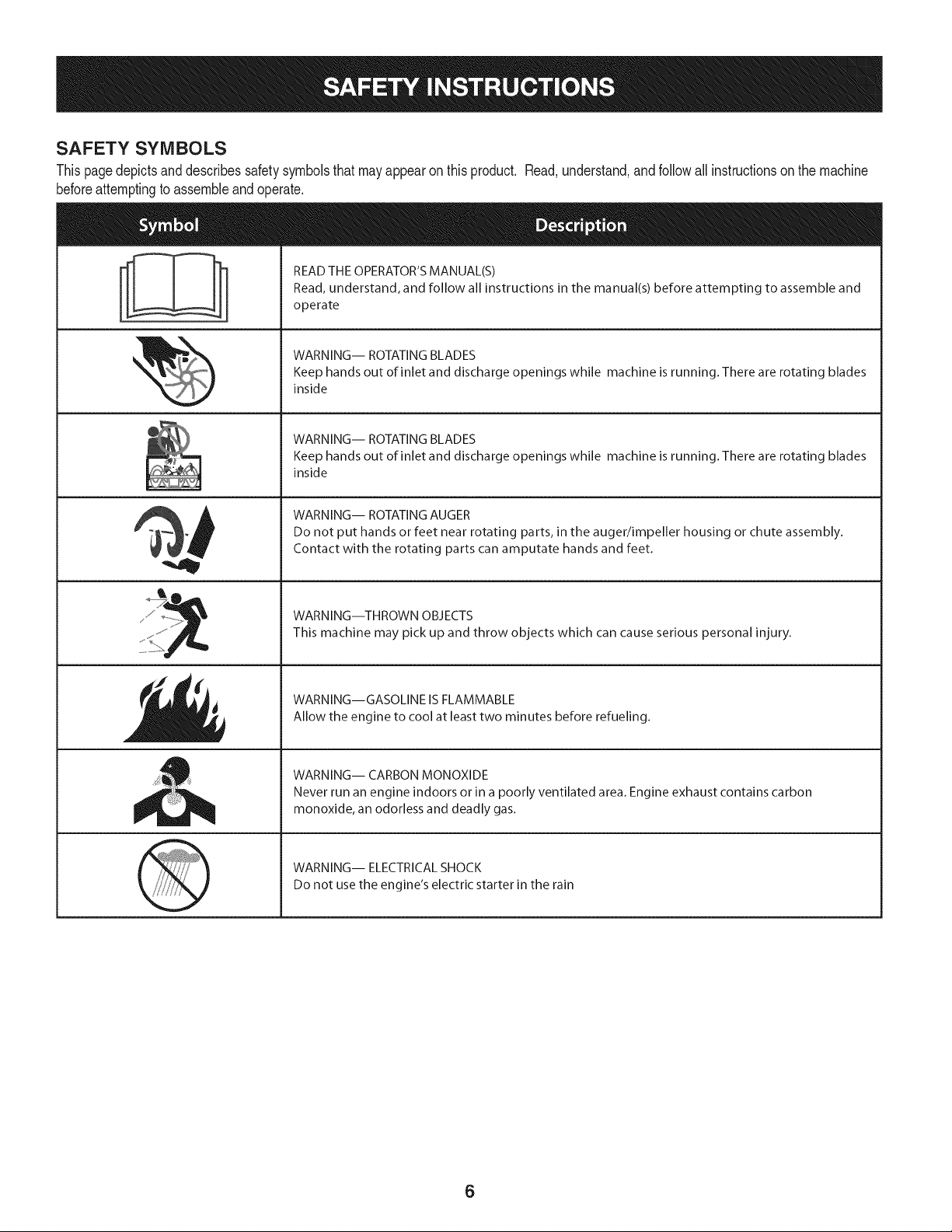
SAFETY SYMBOLS
Thispagedepictsanddescribessafetysymbolsthatmayappearonthisproduct. Read,understand,and followall instructionson the machine
beforeattemptingto assembleand operate.
. +
i
i
'JIp
READ THE OPERATOR'S MANUAL(S)
Read, understand, and follow all instructions in the manual(s) before attempting to assemble and
operate
WARNING-- ROTATING BLADES
Keep hands out of inlet and discharge openings while machine is running. There are rotating blades
inside
WARNING-- ROTATING BLADES
Keep hands out of inlet and discharge openings while machine is running. There are rotating blades
inside
WARNING-- ROTATING AUGER
Do not put hands or feet near rotating parts, in the auger/impeller housing or chute assembly.
Contact with the rotating parts can amputate hands and feet.
WARNING--THROWN OBJECTS
This machine may pick up and throw objects which can cause serious personal injury.
WARNING--GASOLINE IS FLAMMABLE
Allow the engine to cool at least two minutes before refueling.
WARNING-- CARBON MONOXIDE
Never run an engine indoors or in a poorly ventilated area. Engine exhaust contains carbon
monoxide, an odorless and deadly gas+
WARNING-- ELECTRICAL SHOCK
Do not use the engine's electric starter in the rain
6
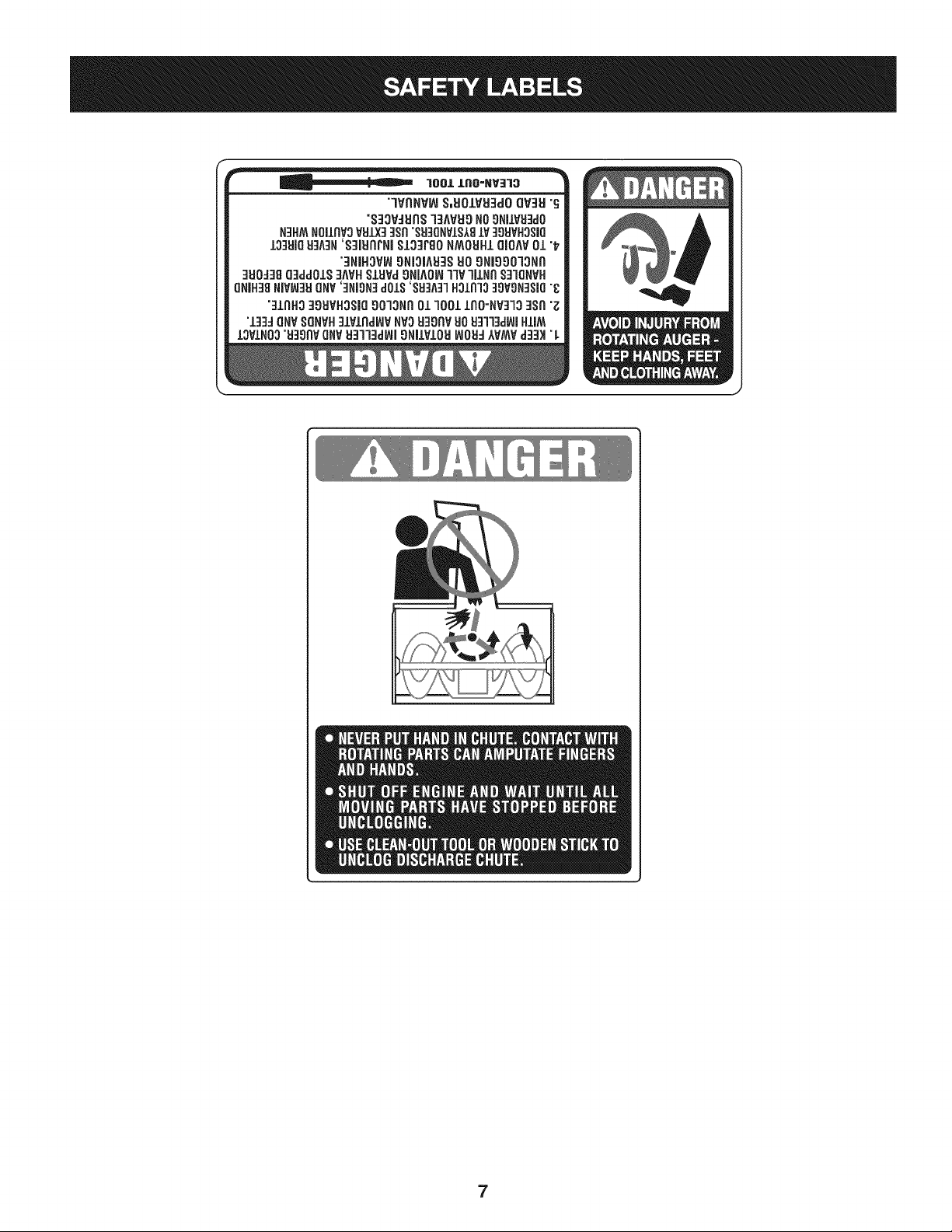
lOOJ.,J.IlO=NV]10
"lVflNV_ S,UOJLVU3dOQV3H"_
"S33VdUnS13AVU9NOgNilVU:ldO
N3HMNOIJ,RVOVtdJ,X33Sll"SU3QNVIS18IV 30UVH3SBQ
13:lUiOH:IA:IN'S3iURrNIS13]F80 NMOUHIQIOAV01 "t_
"_]NiHOV_9Ni31Atd_SUO9NI99013NI'I
:IUO:J3gQ3dd01S3MH S.LUVd9HJAOI_1WlJlHn S31QNVH
QNIH38NiV_:t_lQNV'::lNiON::ldOlS'SH3A:rlH31R133OVON:lSl(]"_
":11AH33OSVHOSiQ90"13NI301 1001 lflO=NV:rl3 :lSfl"_
"1:13dQNV8QHVH:11vlrld_VHVOU39flV}JO_13l13dL_lHJ,IM
IOVlN03"U3911VQNV1:131"13dlAIJ9NllVlOldINO_J:J)_VMVd:13)t"L
7
NOTE:Referencesto rightorleft sideof the snowthrowerare
determinedfrombehindthe unit inthe operatingposition(standing
directlybehindthe snowthrower,facingthe handlepanel).
REMOVING FROM CARTON
1. Cut the cornersof thecartonandlay the sidesflaton the ground.
Removeand discard all packinginserts.
2. Movethe snowthrowerout of thecarton.
3. Makecertainthe cartonhas beencompletelyemptiedbefore
discardingit.
ASSEMBLY
1. Observethe lowerrearareaof the snowthrowerto besure both
cablesarealignedwith rollerguidesbeforepivotingthe handle
upward.
a. Placethe shiftleverin the F6position.
b. Pull up and back on upperhandleas shownin Figure1.As
youare raisingthe handleupward,makesurethat bothends
of the centercablearepositionedproperlyinthe brackets.
Alignupperhandlewiththe lowerhandle.
c. Tightenhandknobssecuringupper handleto lowerhandle.
Removeand discard any rubberbands,if present.Theyare
for packagingpurposesonly.
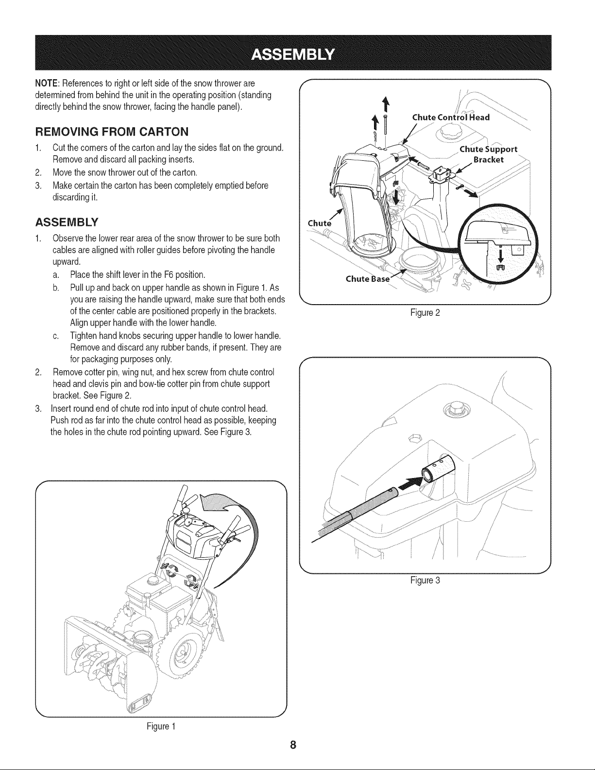
2. Removecotterpin,wing nut, and hexscrewfromchutecontrol
headandclevispinandbow-tiecotterpinfromchutesupport
bracket.SeeFigure2.
3. Insertroundendof chuterodinto inputof chutecontrolhead.
Pushrodas far intothe chutecontrolheadas possible,keeping
the holesin the chuterodpointingupward.SeeFigure3.
t
Chute Control Head
Chute
Figure2
f
// .....
%
Figure3
Figure1
8
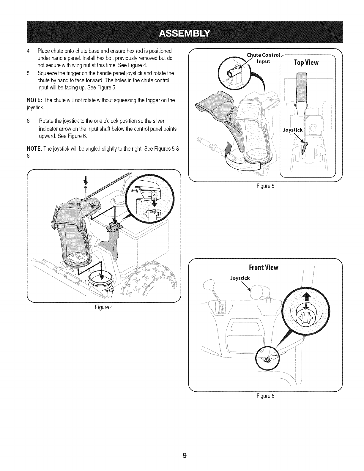
4. Placechuteontochutebaseandensurehexrodis positioned
underhandlepanel.Installhex boltpreviouslyremovedbut do
not securewith wingnut at thistime.See Figure4.
5. Squeezethetriggeron the handlepaneljoystickand rotatethe
chutebyhandto faceforward.The holesinthe chutecontrol
inputwill be facing up. SeeFigure5.
NOTE:The chutewill not rotatewithoutsqueezingthe triggeron the
joystick.
6. Rotatethejoystickto the oneo'clockpositionso the silver
indicatorarrowon the inputshaft belowthe controlpanelpoints
upward.See Figure6.
NOTE:Thejoystickwillbe angledslightlyto the right.See Figures5 &
6.
Figure4
f
Chute Controlf
TopView
_i¸ ............... t _i
Figure5
f
FrontView
Joystick
Figure6
J
9
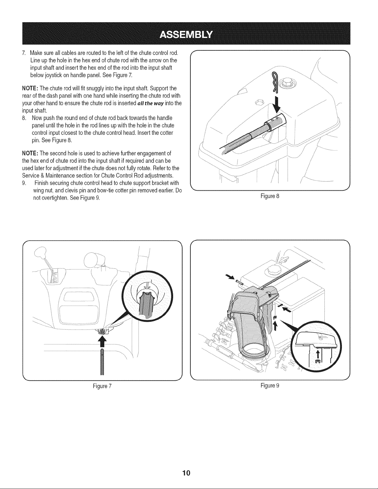
. Makesureall cables are routedto the left of the chutecontrol rod.
Lineupthe hole in the hexendof chuterodwiththe arrowon the
input shaftandinsertthe hex endof the rodintothe input shaft
belowjoystickon handlepanel.SeeFigure7.
NOTE:Thechuterodwill fit snugglyintothe inputshaft. Supportthe
rearof the dash panelwithonehandwhileinsertingthechuterodwith
your otherhandto ensurethechute rod is insertedall the way intothe
inputshaft.
8. Nowpushthe roundend of chuterod backtowardsthe handle
paneluntilthe holein the rod linesup with the holein the chute
controlinputclosestto the chutecontrolhead. Insertthe cotter
pin.SeeFigure8.
NOTE:The secondholeis usedto achievefurtherengagementof
the hex endof chuterodintothe inputshaft if requiredandcan be
usedlaterforadjustmentif thechutedoesnot fully rotate.Refertothe
Service& Maintenancesectionfor ChuteControlRodadjustments.
9. Finishsecuringchutecontrolheadto chute supportbracketwith
wingnut,andclevispinandbow-tiecotter pin removedearlier.Do
notovertighten.SeeFigure9.
/i _
.J
Figure8
\
\,
y..................
Figure7
Figure9
10
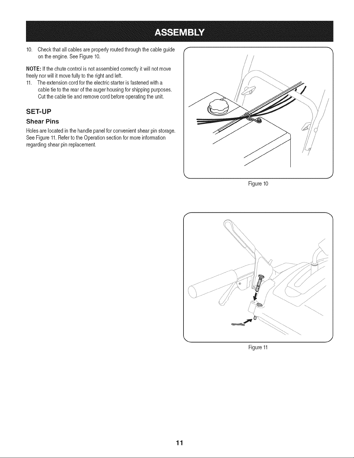
10. Checkthat allcablesareproperlyroutedthroughthecable guide "_
on theengine.SeeFigure10.
NOTE: if the chutecontrolis notassembledcorrectlyit will not move
freelynorwill it movefully to the rightandleft.
11. Theextensioncord forthe electricstarteris fastenedwitha
cabletie to the rearof the auger housingfor shippingpurposes.
Cutthe cabletie and removecord beforeoperatingthe unit.
SET-UP
Shear Pins
Holesare locatedinthe handlepanelfor convenientshearpin storage.
SeeFigure11.Referto the Operationsectionfor moreinformation
regardingshearpin replacement.
Figure10
f
Figure11
J
11
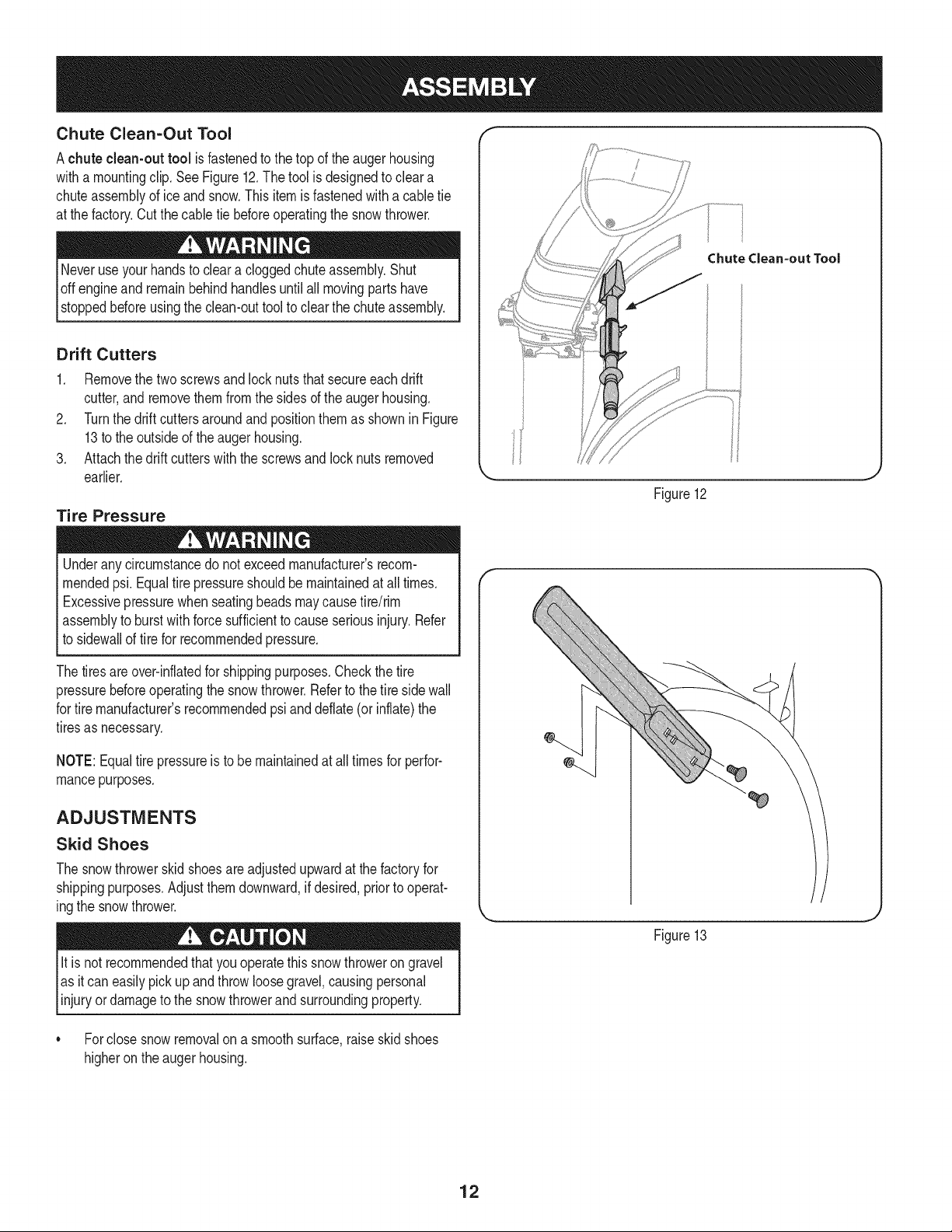
Chute Clean-Out Tool
Achute clean-out tool is fastenedto the top of the augerhousing
witha mountingclip. See Figure12.The tool is designedto cleara
chuteassemblyof ice andsnow.Thisitemis fastenedwitha cabletie
at the factory.Cutthecable tie beforeoperatingthe snowthrower.
loft _1 .allmovingpartshave
stoppedbeforeusingthe clean-outtool to clearthe chuteassembly.
Drift Cutters
1. Removethe two screwsand locknutsthatsecureeach drift
cutter,andremovethem from the sidesof the auger housing.
2. Turnthe drift cutters aroundand positionthemas shown inFigure
13to the outsideof theaugerhousing.
3. Attachthedrift cutterswith the screwsandlocknutsremoved
earlier.
Tire Pressure
Underanycircumstancedo notexceedmanufacturer'srecom-
mendedpsi. Equaltire pressureshouldbe maintainedat all times.
Excessivepressurewhenseatingbeadsmaycausetire/rim
assemblyto burstwithforcesufficientto causeseriousinjury.Refer
to sidewallof tirefor recommendedpressure.
Chutedean-out Tool
Figure12
Thetiresareover-inflatedfor shippingpurposes.Checkthetire
pressurebeforeoperatingthe snow thrower.Referto the tire sidewall
for tiremanufacturer'srecommendedpsianddeflate(or inflate)the
tiresas necessary.
NOTE:Equaltire pressureis to be maintainedat alltimesfor perfor-
mancepurposes.
ADJUSTMENTS
Skid Shoes
The snowthrowerskid shoesare adjustedupwardat thefactoryfor
shippingpurposes.Adjustthemdownward,ifdesired,priorto operat-
ingthe snowthrower.
It isnot recommendedthatyouoperatethis snowthrowerongravel
as itcan easilypickup andthrowloosegravel,causingpersonal
njuryordamageto the snowthrowerand surroundng property.
• Forclosesnowremovalon a smoothsurface,raiseskidshoes
higheronthe augerhousing.
Figure13
12
Usea middleor lowerpositionwhentheareato be clearedis
uneven,such as a graveldriveway.
NOTE:Ifyou chooseto operatethe snowthroweron a gravelsurface,
keepthe skid shoesin positionfor maximumclearancebetweenthe
groundandthe shaveplate.
Operatinga snowthrowerequippedwith steelskidshoesmayresult
indamageto naturalstonepaversurfaces(e.g.sandstone,blue-
stone,limestone). Forinformationonavailablepolymerskidshoes,
call 1-800-4MY-HOME.
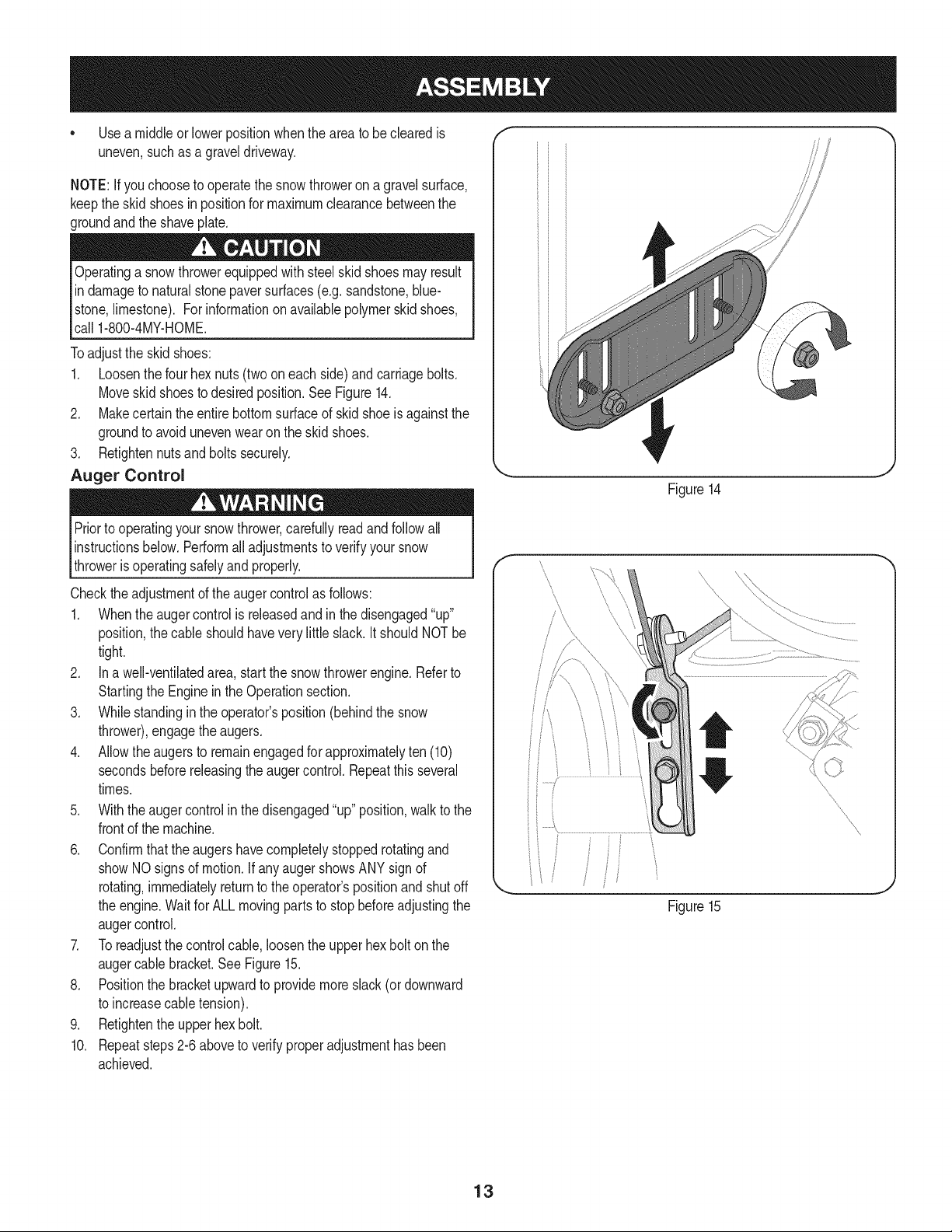
Toadjustthe skidshoes:
1. Loosenthe fourhex nuts(twooneach side)and carriagebolts.
Moveskidshoesto desiredposition.See Figure14.
2. Makecertain theentirebottomsurfaceof skid shoeis againstthe
groundto avoidunevenwearon the skidshoes.
3. Retightennutsandboltssecurely.
Auger Control
Priorto operatingyoursnowthrower,carefullyreadand followall
instructionsbelow.Performalladjustmentsto verifyyour snow
throweris operatingsafelyand properly.
Checktheadjustmentof the augercontrolas follows:
1. Whentheaugercontrolis releasedand in the disengaged"up"
position,the cableshouldhavevery littleslack.ItshouldNOTbe
tight.
2. In a well-ventilatedarea,start the snowthrowerengine.Referto
Startingthe Engineinthe Operationsection.
3. Whilestandingin the operator'sposition(behindthe snow
thrower),engagethe augers.
4. Allowtheaugersto remainengagedfor approximatelyten (10)
secondsbeforereleasingthe augercontrol.Repeatthisseveral
times.
5. With theauger controlin thedisengaged"up" position,walkto the
frontof the machine.
6. Confirmthatthe augershavecompletelystoppedrotatingand
showNOsignsof motion.If anyaugershowsANY signof
rotating,immediatelyreturnto the operator'spositionand shutoff
the engine.Waitfor ALLmovingpartsto stop beforeadjustingthe
augercontrol.
7. Toreadjustthecontrolcable, loosentheupperhexbolt on the
augercablebracket.SeeFigure15.
8. Positionthe bracketupwardto providemoreslack(or downward
to increasecabletension).
9. Retightenthe upperhex bolt.
10. Repeatsteps2-6 aboveto verifyproperadjustmenthasbeen
achieved.
Figure14
J
f
Figure15
f
/
J
13
f
Drive Control
Headlight
GasCap
Shift Lever
F Four-Way Chute ControP (Joystick)
F
F
Auger Control
Heated Grip
Drift Cutter
Chute Assembly
\
\
\
Augers
Skid Shoe
Mumer
\
\
Primer
\
Key
Recoil Starter
Oil Fill
Handle
FUEL LEVEL
Choke
Control Throttle
Control
/
OilDrain
\
Electric
Starter
Button
Electric StarterOutlet
Figure15
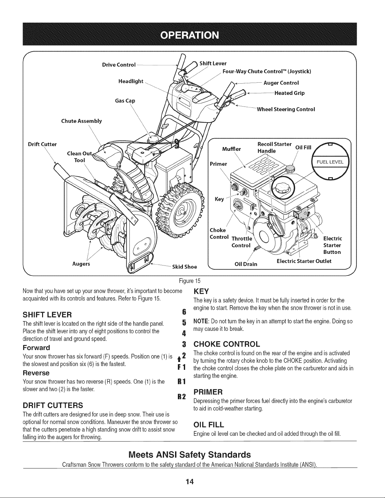
Nowthat youhavesetup yoursnowthrower,it's importantto become
acquaintedwith itscontrolsand features.Referto Figure15.
SHIFT LEVER 6
The shiftleveris locatedonthe rightsideof the handle panel. 5
Placethe shiftleverinto anyof eightpositionsto controlthe 4
directionof travelandgroundspeed.
Forward 3
Yoursnowthrowerhas six forward(F) speeds.Positionone(1)is t 2
the slowestand positionsix (6) is the fastest. F 1
Reverse
Yoursnowthrowerhastwo reverse(R) speeds.One(1)is the
slowerandtwo(2) is the faster.
DRIFT CUTTERS
Thedrift cuttersaredesignedfor use indeepsnow.Theiruse is
optionalfor normalsnowconditions.Maneuverthe snowthrowerso
thatthe cutterspenetratea high standingsnowdrift to assistsnow
fallingintothe augersfor throwing.
KEY
The key is a safetydevice.It mustbefullyinsertedinorderfor the
engineto start.Removethe keywhenthe snowthroweris not inuse.
NOTE: Donot turnthe keyinan attemptto startthe engine.Doingso
maycauseit to break.
CHOKE CONTROL
The chokecontrolis foundon the rearof the engineand is activated
by turningthe rotarychoke knobto the CHOKEposition.Activating
the chokecontrolclosesthe choke plateon thecarburetorand aids in
startingthe engine.
PRIMER
Depressingthe primerforcesfueldirectlyintothe engine'scarburetor
to aid in cold-weatherstarting.
OIL FILL
Engineoil levelcan becheckedandoiladdedthroughthe oil fill.
Meets ANSI Safety Standards
CraftsmanSnowThrowersconformto the safetystandardof the AmericanNationalStandardsInstitute(ANSI).
14
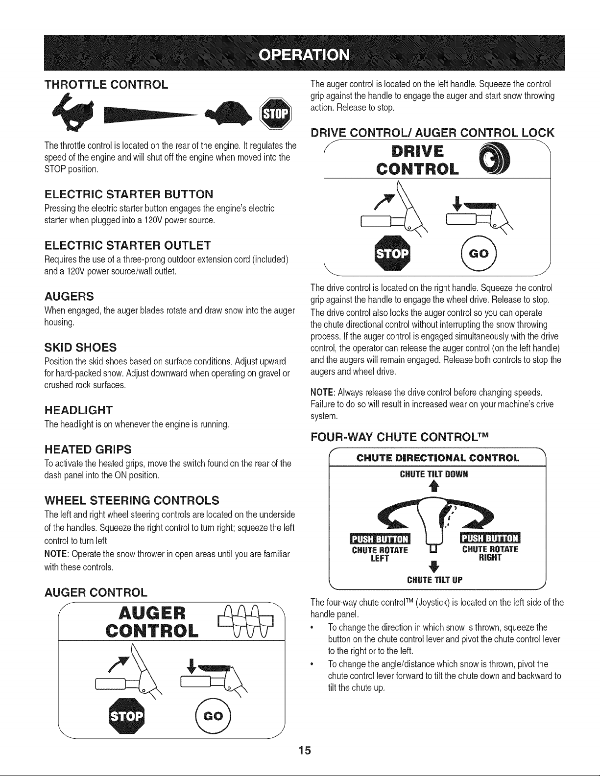
THROTTLE CONTROL
Thethrottlecontrolis locatedon the rearof the engine.It regulatesthe
speedof theengineandwill shutoff the enginewhenmovedintothe
STOPposition.
ELECTRIC STARTER BUTTON
Pressingthe electricstarterbuttonengagesthe engine'selectric
starterwhenpluggedintoa 120Vpowersource.
ELECTRIC STARTER OUTLET
Requiresthe useof athree-prongoutdoorextensioncord(included)
anda 120Vpowersource/walloutlet.
AUGERS
Whenengaged,the augerbladesrotateand drawsnowintothe auger
housing.
SKID SHOES
Positionthe skid shoesbasedon surfaceconditions.Adjustupward
for hard-packedsnow.Adjustdownwardwhenoperatingon gravelor
crushedrocksurfaces.
HEADLIGHT
Theheadlightis on whenevertheengineis running.
HEATED GRIPS
Toactivatethe heatedgrips,movethe switchfoundon the rearof the
dashpanelintothe ON position.
WHEEL STEERING CONTROLS
Theleft andrightwheelsteeringcontrolsarelocatedon theunderside
of the handles.Squeezethe rightcontrolto turn right; squeezethe left
controlto turn left.
NOTE:Operatethe snowthrowerin open areasuntilyou arefamiliar
withthesecontrols.
AUGER CONTROL
The augercontrolis locatedon the left handle.Squeezethe control
gripagainstthe handleto engagethe augerand startsnowthrowing
action.Releaseto stop.
DRIVE CONTROL/AUGER CONTROL LOCK
DRIVE
CONTROL
The drivecontrolis locatedon the righthandle.Squeezethe control
gripagainstthe handleto engagethe wheeldrive.Releaseto stop.
The drivecontrolalso lockstheaugercontrolso youcan operate
the chute directionalcontrolwithoutinterruptingthe snowthrowing
process.If the augercontrolis engagedsimultaneouslywith the drive
control,the operatorcan releasethe augercontrol(onthe left handle)
andthe augerswill remainengaged.Releaseboth controlsto stop the
augersandwheeldrive.
NOTE:Alwaysreleasethedrivecontrol beforechangingspeeds.
Failureto do so will result in increasedwearon yourmachine'sdrive
system.
FOUR=WAY CHUTE CONTROL TM
CHUTE DiRECTiONAL CONTROL
CHUTETiLTDOWN
t
CHUTEROTATE CHUTEROTATE
LEFT RIGHT
CHUTETiLTUP
j,
The four-waychutecontrolTM (Joystick)is locatedon theleft sideof the
handlepanel.
* Tochangethe directioninwhichsnowis thrown,squeezethe
buttononthe chutecontrolleverand pivotthe chutecontrollever
to the rightor to the left.
* Tochangethe angle/distancewhichsnowisthrown,pivotthe
chutecontrolleverforwardto tiltthe chutedownand backwardto
tilt the chuteup.
15
CLEAN-OUT TOOL
Neveruseyourhandsto cleara cloggedchuteassembly.Shut
loft engineand remainbehindhandlesuntil allmovingpartshave
lstoppedbeforeusingtheclean-outtool to clearthe chuteassembly.
Thechuteclean-outtool is convenientlyfastenedto the rear of the
augerhousingwitha mountingclip. Shouldsnowand ice become
lodgedin thechuteassemblyduringoperation,proceedas followsto
safelycleanthechuteassemblyandchuteopening:
1. Releaseboththe AugerControlandthe DriveControl.
2. Stopthe engineby removingthe ignitionkey.
3. Removethe clean-outtoolfrom the clip whichsecuresit to the
rearof the augerhousing.
4. Use the shovel-shapedend of theclean-outtool to dislodgeand
scoopany snowand icewhichhasformedin andnearthechute
assembly.
5. Refastenthe clean-outtool to the mountingclip on the rearof
theaugerhousing,reinsertthe ignitionkey and startthe snow
thrower'sengine.
6. Whilestandingin the operator'sposition(behindthesnow
thrower),engagethe augercontrolfora fewsecondsto clear any
remainingsnowandice from thechuteassembly.
BEFORE STARTING ENGINE
Read,understand,and followall instructionsandwarningson the
machineand in this manualbeforeoperating.
Oil
Theunit wasshippedwith oil in the engine.Checkoil levelbefore
eachoperationto ensureadequateoil inthe engine.Forfurther
instructions,refertothe stepson page 18.
NOTE:Besureto checkthe engineon a levelsurfacewith the engine
stopped.
1. Removethe oil fillercap/dipstickand wipethe dipstickclean.
2. insertthe cap/dipstickintothe oil filler neck,andtightenthe cap
until seated.
3. Removethe oil fillercap/dipstick,ifthe levelislow,slowlyadd
oil (5%30, witha minimumclassificationof SF/SG)untiloil level
registersbetweenhigh(H) andlow(L).
NOTE:Do notoverfill.Overfillingwithoil mayresultinenginesmoking,
hardstartingor spark plugfouling.
4. Replaceandtightencap/dipstickfirmlybeforestartingengine.
Gasoline
Useautomotivegasoline(unleadedor low leadedto minimizecombus-
tionchamberdeposits)witha minimumof 87octane.Gasolinewith
upto 10%ethanolor 15%MTBE(MethylTertiaryButyl Ether)canbe
used.Neveruseanoil/gasolinemixtureor dirtygasoline.Avoidgetting
dirt,dust,or waterinthefuel tank. DO NOTuse E85gasoline.
• Refuelin a well-ventilatedarea with the enginestopped.Do not
smokeorallowflamesor sparksin the areawherethe engineis
refueledor wheregasolineisstored.
• Donot overfillthe fueltank.After refueling,makesurethe tank
cap is closedproperlyandsecurely.
• Be carefulnotto spillfuel whenrefueling.Spilledfuel or fuel vapor
mayignite,ifany fuelis spilled,makesurethe area isdry before
startingthe engine.
• Avoidrepeatedorprolongedcontact with skinor breathingof
)or.
Useextremecarewhen handlinggasoline.Gasolineis extremely
flammableandthevaporsare explosive.Never fuelthe machine
indoorsorwhilethe engineis hotor running.Extinguishcigarettes,
cigars,pipesandothersourcesof ignition.
1. Cleanaroundfuel fill beforeremovingcap to fuel.
2. A fuel levelindicatoris locatedin the fueltank. See Figure15
inset. Be carefulnotto overfill.Filltank untilfuel reachesthe fuel
level indicatorto allowspacefor fuel expansion.
STARTING THE ENGINE
Alwayskeep handsandfeetclearof movingparts. Donot usea
pressurizedstartingfluid.Vaporsare flammable.
NOTE:Allowthe engineto warm up for a fewminutesafter starting.
The enginewill notdevelopfull poweruntilit reachesoperating
temperatures.
1. Makecertainboththe augercontrolanddrivecontrolarein the
disengaged(released)position.
2. insert keyinto slot. Makesureit snapsintoplace.Donot attempt
to turn the key.
NOTE: Theenginecannotstartwithoutthe keyfully insertedintothe
ignitionswitch.
Electric Starter
The optionalelectricstarteris equippedwith a groundedthree-wire
powercordandplug,and is designedto operateon 120voltAC
householdcurrent.It mustbe usedwith a properlygroundedthree-
prongreceptacleat all timesto avoidthe possibilityof electricshock.
Followall instructionscarefullyprior to operatingtheelectricstarter.
DONOTuse electricstarterinthe rain.
Determinethat yourhome'swiringis a three-wiregroundedsystem.
Aska licensedelectricianif you arenotcertain.
Ifyou havea groundedthree-prongreceptacle,proceedas follows.
Ifyou do not havethe properhousewiring, DONOT usethe electric
starterunderanyconditions.
1. Plugthe extensioncord intothe outletlocatedon the engine's
surface.Plugthe otherend of extensioncord intoa three-prong
120-volt,grounded,AC outlet in a well-ventilatedarea.
16
2. Movethrottlecontrolto FAST(rabbit)'_ position.
3. Movechoketo the CHOKEIJl position(coldenginestart). If
engineis warm,placechokein RUNposition.
4. Pushprimerthree (3) times, makingsureto coverventholein
primerbulbwhen pushing.If engineis warm,pushprimeronly
once.Alwayscoverventholewhenpushing.Coolweathermay
requireprimingto be repeated.
5. Pushstarterbuttonto start engine.Oncethe enginestarts,im-
mediatelyreleasestarterbutton.Electricstarteris equippedwith
thermaloverloadprotection;systemwill temporarilyshut-downto
allowstarterto cool if electricstarterbecomesoverloaded.
6. As theenginewarms,slowlyrotatethe chokecontrolto RUN
position.If the enginefalters,restartengineand run with choke
at half-chokepositionfor a shortperiodof time,andthen slowly
rotatethe chokeinto RUNposition.
7. After engineis running,disconnectpowercordfrom electric
starter.Whendisconnecting,alwaysunplugthe end at the wall
outletbeforeunpluggingtheoppositeendfromthe engine.
Recoil Starter
TO ENGAGE DRIVE
1. Withthe throttlecontrolin the Fast(rabbit) position,moveshift
leverinto oneof the six forward(F) positionsor two reverse(R)
positions.Selecta speedappropriatefor thesnowconditionsand
a paceyou'recomfortablewith.
NOTE: When selectinga DriveSpeed,use the slowerspeedsuntil
you are comfortableandfamiliarwiththe operationof the snow
thrower.
2. Squeezethe drivecontrolagainstthe handleandthe snow
throwerwill move.Releaseit anddrive motionwill stop.
NOTE:NEVERrepositionthe shiftlever(changespeedsordirection
of travel)withoutfirst releasingthe drivecontrol and bringingthe snow
throwerto a completestop.Doingsowill resultin prematurewearto
the snow thrower'sdrivesystem.
TO ENGAGE AUGER
1. Toengagethe augerand startthrowingsnow,squeezethe auger
controlagainstthe left handle.Releaseto stopthe auger.
Do notpull the starterhandlewhilethe enginerunning.
1. Movethrottlecontrolto FAST(rabbit)'_ position.
2. Movechoketo the CHOKEI,'_1 position(coldenginestart).If
engineis warm,placechokein RUNposition.
3. Pushprimerthree (3) times, makingsureto coverventholewhen
pushing.Ifengineiswarm,push primeronlyonce. Alwayscover
ventholewhen pushing.Coolweathermayrequireprimingto be
repeated.
4. Pull gentlyon the starterhandleuntil it beginsto resist,then
pullquicklyandforcefullyto overcomethe compression.Engine
shouldstart.Donot releasethe handleandallow it to snapback.
ReturnropeSLOWLYto originalposition.If required,repeatthis
step.
5. As theenginewarms,slowlyrotatethe chokecontrolto RUN
position.If the enginefalters,restartengineand run with choke
at half-chokepositionfor a shortperiodof time,andthen slowly
rotatethe chokeinto RUNposition.
To avoidunsupervisedengineoperation,neverleavethe machine
unattendedwiththe enginerunning.Turnthe engineoffafter useand
removekey.
STOPPING THE ENGINE
Afteryouhavefinishedsnow-throwing,runenginefora few minutes
beforestoppingto help dry offany moistureonthe engine.
1. Movethrottlecontrolto OFFposition.
2. Removethekey.Removingthe keywill reducethe possibilityof
unauthorizedstartingof the enginewhileequipmentis notin use.
Keepthe keyin a safe place.The enginecannotstart withoutthe
key.
3. Wipeany moistureawayfrom the controlson theengine.
17
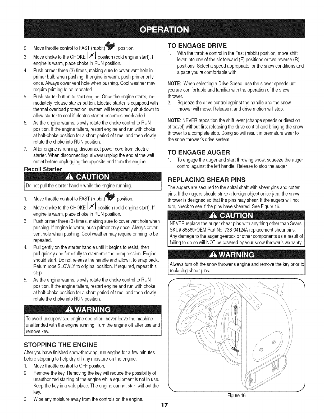
REPLACING SHEAR PiNS
The augersare securedto the spiralshaftwith shearpins andcotter
pins.If the augersshouldstrikea foreignobject or ice jam,the snow
throweris designedso thatthe pins mayshear.If theaugerswill not
turn,checkto see if the pins havesheared.See Figure16.
NEVERreplacethe augershearpinswithanythingotherthan Sears
SKU#88389/0EM PartNo.738-04124Areplacementshearpins.
Anydamageto theaugergearboxor other componentsas a resultof
failingto do sowill NOTbecoveredbyyour snowthrower'swarranty.
Alwaysturn off thesnowthrower'sengineand removethe keypriorto
replacingshearpins.
if -,
Figure16
MAINTENANCE SCHEDULE
Beforeperforminganytypeofmaintenance/service,disengageall
controlsand stoptheengine.Waituntilallmovingpartshavecometo
acompletestop.Disconnectsparkplugwireandgrounditagainstthe
enginetopreventunintendedstarting.Alwayswearsafetyglassesduring
operationor whileperforminganyadjustmentsor repairs.
EachUseandevery5
hours
1st5 hours
Annuallyor 25 hours
Annuallyor 50 hours
Annuallyor 100hours
BeforeStorage
1. Engineoil level
2. Looseor missinghardware
3. Unit and engine.
1. Engineoil
1. Sparkplug
2. Controllinkagesand pivots
3. Wheels
4. Gear shaftand Augershaft
1. Engineoil
1. Sparkplug
1. Fuelsystem
Followthe maintenanceschedulegiven below.This chart describes
serviceguidelinesonly. Usethe ServiceLogcolumnto keeptrackof
completedmaintenancetasks.To locate the nearest Sears Service
Centeror to scheduleservice,simplycontactSearsat
1-800-4-MY-HOME®.
1. Check
2. Tightenor replace
3. Clean
1. Change
1. Check
2. Lubewith light oil
3. Lubewith multipurposeautogrease
4. Lubewith light oil
1. Change
1. Change
1. Runengineuntilit stopsfromlack
d fuel
ENGINE MAINTENANCE
Checking Engine Oil
Beforelubricating,repairing,or inspecting,disengageall controls
Iandstopengine.Waituntilall movingpartshavecometo a complete
_stop.
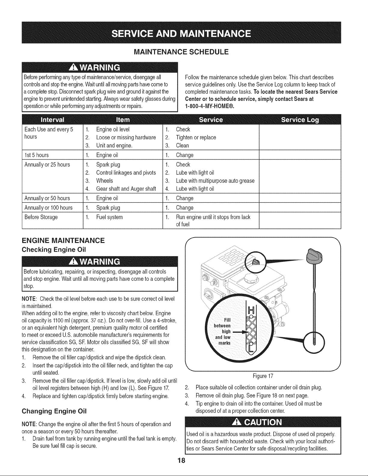
NOTE: Checktheoil levelbeforeeachuseto besurecorrectoil level
is maintained.
Whenaddingoilto the engine,referto viscositychart below.Engine
oilcapacityis 1100ml (approx.37oz.). Donot over-fill.Usea 4-stroke,
oran equivalenthighdetergent,premiumqualitymotoroilcertified
to meet or exceedU.S.automobilemanufacturer'srequirementsfor
serviceclassificationSG, SR MotoroilsclassifiedSG, SFwill show
thisdesignationon the container.
1. Removethe oil fillercap/dipstickand wipethe dipstickclean.
2. Insertthe cap/dipstickintothe oilfiller neck,andtightenthe cap
until seated.
3. Removethe oil fillercap/dipstick.If levelislow, slowlyadd oiluntil
oil levelregistersbetweenhigh (H) andlow (L). SeeFigure17.
4. Replaceandtightencap/dipstickfirmlybeforestartingengine.
Changing Engine Oil
NOTE:Changethe engineoil after the first 5 hoursof operationand
oncea seasonorevery50 hoursthereafter.
1. Drainfuelfrom tank by runningengineuntilthe fuel tank isempty.
Besurefuel fill cap is secure.
J
Figure17
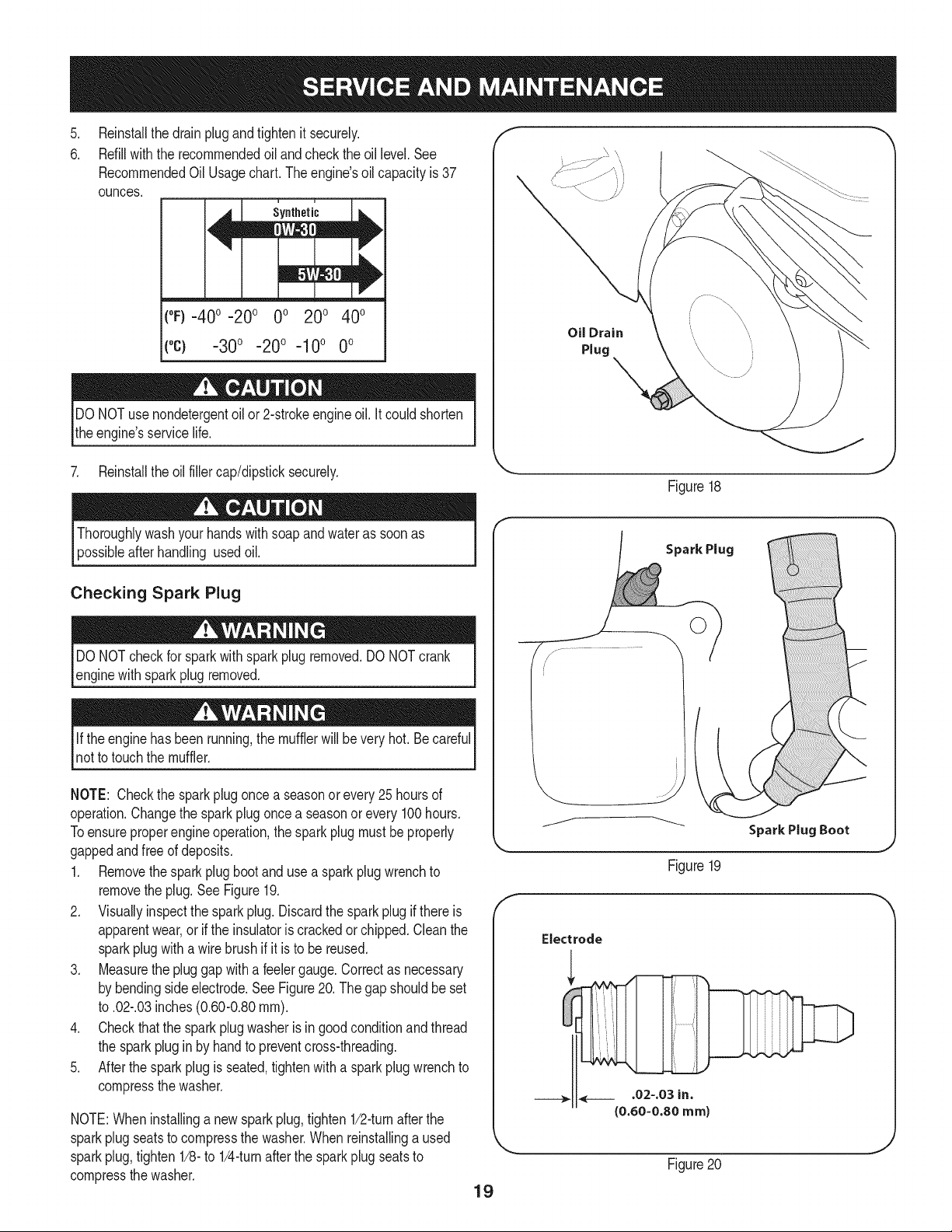
2. Placesuitableoil collectioncontainerunderoil drainplug.
3. Removeoil drainplug.SeeFigure18on nextpage.
4. Tip engineto drainoil intothe container.Usedoil mustbe
disposedof at a propercollectioncenter.
Usedoil isa hazardouswasteproduct.Disposeof usedoil properly.
IDo notdiscardwithhouseholdwaste.Checkwithyour localauthori-
lties or SearsService Centerfor safe disposal/recyclingfacilities.
18
.
6.
Reinstallthe drainplugandtightenit securely.
Refillwiththe recommendedoil andcheckthe oil level.See
RecommendedOil Usagechart.Theengine'soil capacityis 37
ounces.
, ,
[
(%-40 °-20 o 0o 200 400
("c) -300 -200 -10° 0°
DO NOTuse nondetergentoilor 2-strokeengineoil. It could shorten
the engine'sservicelife.
Oil Drain
Plug
7. Reinstallthe oil fillercap/dipsticksecurely.
Figure18
Thoroughlywashyour handswithsoap andwater as soonas
possibleafterhandling usedoil.
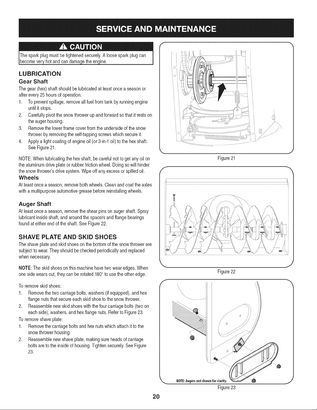
Checking Spark Plug
DO NOTcheckfor sparkwithsparkplugremoved.DO NOTcrank
enginewithsparkplug removed.
Ifthe enginehas beenrunning,the mufflerwill be very hot. Be careful
notto touchthe muffler.
NOTE: Checkthe sparkplugoncea seasonorevery25hoursof
operation.Changethe sparkplugoncea seasonor every 100hours.
Toensureproperengineoperation,the sparkplugmustbe properly
gappedandfreeof deposits.
1. Removethesparkplugbootanduse a sparkplug wrenchto
removethe plug.See Figure19.
2. Visuallyinspectthe spark plug.Discardthe sparkplugif thereis
apparentwear,orif the insulatoris crackedor chipped.Cleanthe
sparkplugwitha wirebrush if it is to be reused.
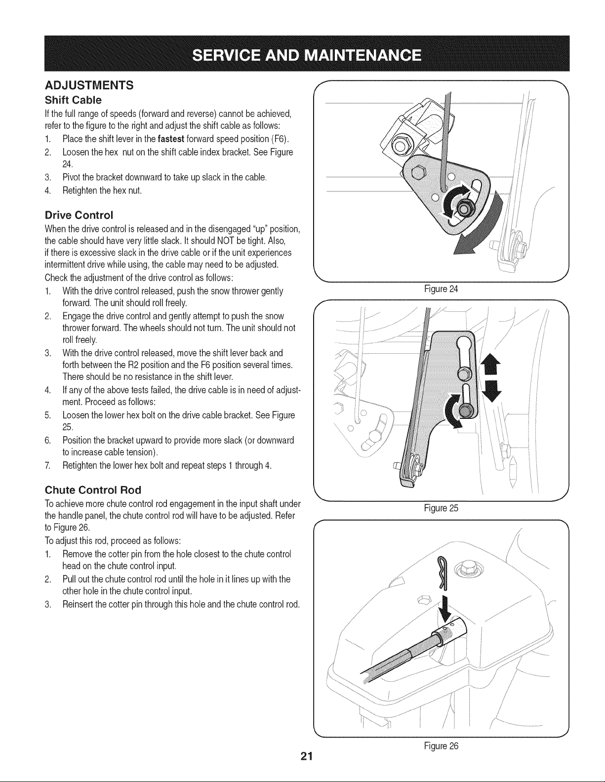
3. Measurethe plug gap with a feelergauge.Correctas necessary
by bendingsideelectrode.See Figure20. Thegap shouldbe set
to .02-.03inches(0.60-0.80ram).
4. Checkthatthe sparkplug washeris ingoodconditionandthread
the sparkplug in by handto preventcross-threading.
5. After thespark plug is seated,tightenwitha sparkplugwrenchto
compressthe washer.
NOTE:Wheninstallinga newsparkplug,tighten1/2-turnafter the
sparkplugseatsto compressthe washer.Whenreinstallinga used
sparkplug,tighten1/8-to 1/4-turnafterthe sparkplugseatsto
compressthe washer.
19
Spark Plug
O
J
SparkPlug Boot
Figure19
Electrode
.02=.03 in.
(0.60-0.80 ram)
Figure20
hotandcan ine.
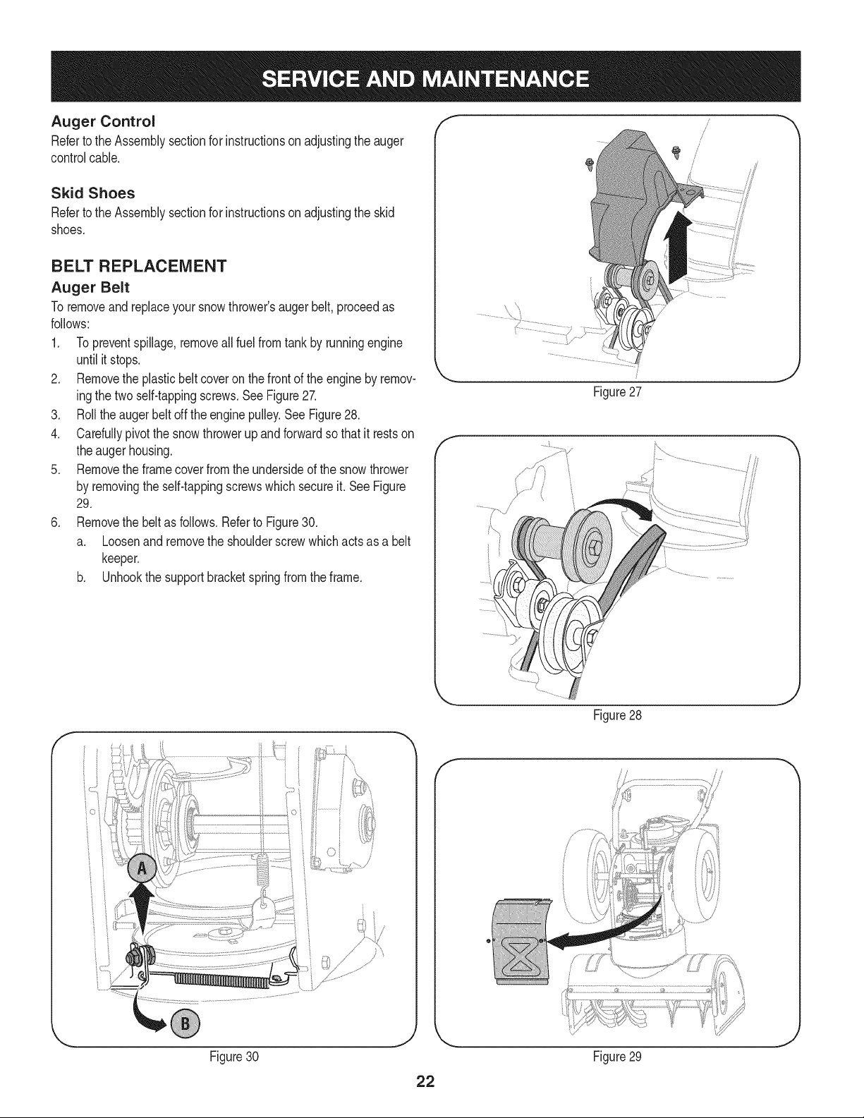
LUBRICATION
Gear Shaft
Thegear(hex)shaft shouldbe lubricatedat least oncea seasonor
afterevery25 hoursof operation.
1. Topreventspillage,removeall fuel fromtank by runningengine
until it stops.
2. Carefullypivotthe snowthrowerup and forwardso that it restson
theaugerhousing.
3. Removethe lowerframecover fromthe undersideof the snow
throwerby removingthe self-tappingscrewswhich secureit.
4. Applya lightcoatingof engineoil (or3-in-1oil) to the hexshaft.
SeeFigure21.
NOTE:Whenlubricatingthe hexshaft,be carefulnotto get any oil on
thealuminumdriveplateor rubberfrictionwheel.Doingsowill hinder
the snowthrower'sdrive system.Wipeoff anyexcessor spilledoil.
Wheels
At least oncea season,removebothwheels.Cleanandcoattheaxles
witha multipurposeautomotivegreasebeforereinstallingwheels.
Auger Shaft
At least oncea season,removethe shearpinson augershaft. Spray
lubricantinsideshaft,andaroundthe spacersand flangebearings
foundat eitherendof the shaft.SeeFigure22.
SHAVE PLATE AND SKID SHOES
The shaveplateand skid shoeson the bottomof the snowthrowerare
subjectto wear.They shouldbe checkedperiodicallyand replaced
whennecessary.
NOTE:Theskidshoeson thismachinehavetwowearedges.When
onesidewearsout,theycan be rotated1800to usethe otheredge.
To removeskidshoes:
1. Removethe two carriagebolts,washers(if equipped),andhex
flangenutsthat secureeach skid shoeto the snowthrower.
2. Reassemblenew skidshoeswiththe fourcarriagebolts (twoon
eachside),washers,and hex flangenuts.Referto Figure23.
To removeshaveplate:
1. Removethe carriageboltsand hexnuts whichattachit to the
snowthrowerhousing.
2. Reassemblenew shaveplate,makingsureheadsof carriage
boltsareto the insideof housing.Tightensecurely.SeeFigure
23.
)
// "?X
/ .... )
{;:7/
7/' ................
f
Figure21
J
Figure22
f
\
\
\
2O
NOTE:Augersnotshown for clarity.
Figure23
ADJUSTMENTS
Shift Cable
If thefull rangeof speeds(forwardandreverse)cannotbe achieved,
referto the figureto the rightand adjustthe shift cableas follows:
1. Placethe shiftleverin thefastest forwardspeedposition(F6).
2. Loosenthe hex nuton the shiftcable indexbracket.SeeFigure
24.
3. Pivotthe bracketdownwardto takeupslack in the cable.
4. Retightenthehex nut.
Drive Control
Whenthedrivecontrolis releasedand in thedisengaged"up"position,
the cableshouldhavevery little slack.It shouldNOTbe tight. Also,
if thereis excessiveslackin thedrive cableor if the unitexperiences
intermittentdrivewhileusing,the cable mayneedto be adjusted.
Checktheadjustmentof the drivecontrolas follows:
1. Withthedrivecontrolreleased,pushthe snowthrowergently
forward.The unitshouldrollfreely.
2. Engagethe drivecontroland gently attemptto pushthe snow
throwerforward.Thewheelsshouldnotturn.The unitshouldnot
rollfreely.
3. With thedrivecontrol released,movethe shift leverbackand
forthbetweenthe R2positionandthe F6 positionseveraltimes.
Thereshouldbeno resistancein the shiftlever.
4. If anyof the abovetests failed,the drivecable is in needof adjust-
ment.Proceedas follows:
5. Loosenthe lowerhexbolt on the drivecable bracket.SeeFigure
25.
6. Positionthe bracketupwardto providemoreslack(or downward
to increasecabletension).
7. Retightenthe lowerhex boltand repeatsteps1 through4.
Chute Control Rod
Toachievemorechutecontrolrodengagementinthe input shaftunder
the handlepanel,the chutecontrolrodwill haveto beadjusted.Refer
to Figure26.
Toadjustthis rod,proceedas follows:
1. Removethecotterpin fromthe hole closestto the chute control
headon thechutecontrolinput.
2. Pull outthe chutecontrolroduntilthe holein it lines up with the
otherholeinthe chute controlinput.
3. Reinsertthe cotterpin throughthis hole and thechute controlrod.
f
.........
Figure25
J
\
\
/
/ ,
J
J
Figure26
21
Auger Control f "_
Referto the Assemblysectionfor instructionsonadjustingtheauger
controlcable. _'
Skid Shoes
Referto the Assemblysectionfor instructionsonadjustingthe skid
shoes.
BELT REPLACEMENT
Auger Belt
To removeandreplaceyoursnow thrower'saugerbelt,proceedas
follows:
1. Topreventspillage,removeall fuel fromtank by runningengine
until itstops.
2. Removethe plasticbelt coveronthe front of the engineby remov-
ingthe two self-tappingscrews.SeeFigure27.
3. Rollthe augerbeltoff theenginepulley.See Figure28.
4. Carefullypivotthe snowthrowerup and forwardso that itrestson
theaugerhousing.
5. Removethe frame coverfrom the undersideof the snow thrower
by removingthe self-tappingscrewswhich secureit. See Figure
29.
6. Removethe beltas follows.Referto Figure30.
a. Loosenand removethe shoulderscrewwhich actsas a belt
keeper.
b. Unhookthe supportbracketspringfromthe frame.
Figure27
J
f
Figure28
J
f
Figure30 Figure29
J
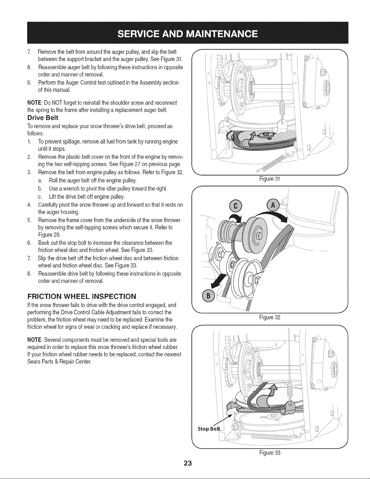
7. Removethebeltfromaroundtheaugerpulley,andslipthebelt
betweenthesupportbracketandtheaugerpulley.SeeFigure31.
8. Reassembleaugerbeltbyfollowingtheseinstructionsinopposite
orderandmannerofremoval.
9. PerformtheAugerControltestoutlinedintheAssemblysection
ofthismanual.
NOTE:DoNOTforgettoreinstalltheshoulderscrewandreconnect
thespringtotheframeafterinstallingareplacementaugerbelt.
Drive Belt
Toremoveand replaceyoursnow thrower'sdrivebelt, proceedas
follows:
1. Topreventspillage,removeallfuel fromtankby runningengine
untilit stops.
2. Removetheplasticbelt coveronthe frontof the engineby remov-
ingthe two self-tappingscrews.See Figure27on previouspage.
3. Removethebelt from enginepulleyas follows.Referto Figure32.
a. Rollthe augerbeltoff theenginepulley.
b. Use a wrenchto pivotthe idlerpulleytowardthe right.
c. Liftthe drivebelt off enginepulley.
4. Carefullypivotthe snowthrowerup and forwardsothat itrestson
the augerhousing.
5. Removetheframecoverfromthe undersideof the snowthrower
by removingthe self-tappingscrewswhichsecureit.Referto
Figure29.
6. Back outthe stopbolt to increasethe clearancebetweenthe
frictionwheeldiscandfrictionwheel.SeeFigure33.
7. Slipthe drivebelt offthe frictionwheeldiscandbetweenfriction
wheelandfrictionwheeldisc.SeeFigure33.
8. Reassembledrive beltby followingtheseinstructionsin opposite
orderand mannerof removal.
FRICTION WHEEL INSPECTION
If the snowthrowerfailsto drivewith thedrivecontrolengaged,and
performingthe DriveControlCableAdjustmentfailsto correctthe
problem,the frictionwheelmayneedto be replaced.Examinethe
frictionwheelfor signsof wearor crackingandreplaceif necessary.
NOTE:Severalcomponentsmustbe removedand specialtools are
requiredinorderto replacethis snowthrower'sfrictionwheelrubber.
If yourfrictionwheel rubberneedsto bereplaced,contact the nearest
SearsParts& RepairCenter.
iO i
Figure31
f
Figure32
J
Stop Bol
Figure33
23
Ifthe snowthrowerwillnot be usedfor30 daysor longer,or if it is the endof the snowseasonwhenthe lastpossibilityof snowis gone,the
equipmentneedsto be storedproperly.Followstorageinstructionsbelowto ensuretop performancefrom the snowthrowerfor manymoreyears.
PREPARING ENGINE
Enginesstoredover30daysneedto be drainedof fuel to prevent
deteriorationandgumfromforminginfuel systemor onessential
carburetorparts.If thegasolineinyourenginedeterioratesduring
storage,youmayneedto havethe carburetor,and otherfuel system
components,servicedor replaced.
1. Removeall fuel fromtank by runningengineuntil it stops.Donot
attemptto pourfuel from the engine.
2. Changethe engineoil.
3. Removesparkplugandpourapproximately1oz.(30 rnl)of clean
engineoil intothe cylinder.Pullthe recoilstarterseveraltimesto
distributetheoil, and reinstallthe spark plug.
4. Cleandebrisfromaroundengine,andunder,around,and behind
muffler.Applya lightfilm of oilon anyareasthatare susceptible
to rust.
• Storeina clean,dry andwellventilatedareaawayfromanyap-
pliancethatoperateswithaflameor pilotlight,suchas a furnace,
waterheater,or clothesdryer.Avoidany areawitha spark
producingelectricmotor,or wherepowertoolsare operated.
Neverstoresnowthrowerwith fuel intank indoorsor inpoorlyventi-
latedareas,wherefuel fumesmay reachan openflame,sparkor pilol
lightas on a furnace,water heater,clothesdryer orgas appliance.
• If possible,avoidstorageareaswith high humidity.
• Keepthe enginelevelin storage.Tiltingcan causefuel oroil
leakage.
PREPARING SNOW THROWER
Whenstoringthe snowthrowerin anunventilatedormetalstor-
age shed,careshouldbetakento rustprooftheequipment.Using
a light oil or silicone,coattheequipment,especiallyanychains,
springs,bearingsandcables.
• Removealldirt fromexteriorof engineand equipment.
• Followlubricationrecommendations.
• Storeequipmentin a clean,dry area.
24
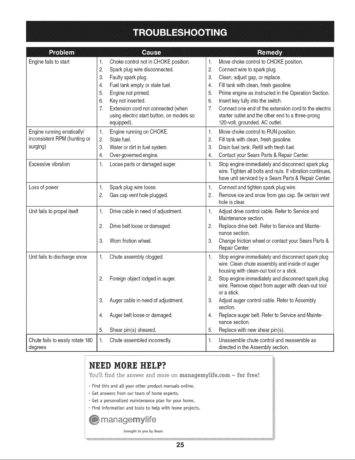
Enginefails to start
Enginerunningerratically/
inconsistentRPM(huntingor
surging)
Excessivevibration
Lossof power
Unitfailsto propel itself
Unitfailsto dischargesnow
1. Chokecontrolnot inCHOKEposition.
2. Sparkplugwire disconnected.
3. Faultysparkplug.
4. Fueltank emptyor stalefuel.
5. Enginenot primed.
6. Keynot inserted.
7. Extensioncordnot connected(when
usingelectricstartbutton,on modelsso
equipped).
1. Enginerunningon CHOKE.
2. Stalefuel.
3. Wateror dirt in fuel system.
4. Over-governedengine.
1. Loosepartsor damagedauger.
1. Sparkplugwire loose.
2. Gascap ventholeplugged.
1. Drivecable inneedof adjustment.
2. Drivebelt looseor damaged.
3. Wornfrictionwheel.
1. Chuteassemblyclogged.
2. Foreignobjectlodgedin auger.
3. Augercablein needof adjustment.
4. Augerbelt looseordamaged.
5. Shearpin(s) sheared.
1. Chuteassembledincorrectly.
1. Movechokecontrolto CHOKEposition.
2. Connectwireto sparkplug.
3. Clean,adjustgap,or replace.
4. Filltank with clean,freshgasoline.
5. Primeengineas instructedinthe OperationSection.
6. Insertkeyfully intothe switch.
7. Connectoneendof the extensioncordto the electric
starteroutletandthe otherendto a three-prong
120-volt,grounded,ACoutlet.
1. Movechokecontrolto RUNposition.
2. Filltank with clean,freshgasoline.
3. Drainfueltank. Refillwithfreshfuel.
4. ContactyourSearsParts & RepairCenter.
1. Stopengineimmediatelyand disconnectsparkplug
wire.Tightenall boltsand nuts.Ifvibrationcontinues,
haveunit servicedbya SearsParts& RepairCenter.
1. Connectandtightensparkplugwire.
2. Removeiceand snowfromgascap. Becertainvent
holeis clear.
1. Adjustdrivecontrolcable. Referto Serviceand
Maintenancesection.
2. Replacedrive belt. Referto Serviceand Mainte-
nancesection.
3. Changefrictionwheelorcontactyour SearsParts&
RepairCenter.
1. Stopengineimmediatelyand disconnectsparkplug
wire.Cleanchuteassemblyand insideof auger
housingwithclean-outtoolor a stick.
2. Stopengineimmediatelyand disconnectsparkplug
wire.Removeobjectfrom augerwith clean-outtool
ora stick.
3. Adjustaugercontrolcable. Referto Assembly
section.
4. Replaceaugerbelt.Referto Serviceand Mainte-
nancesection.
5. Replacewith newshearpin(s).
Chutefailsto easily rotate 180 1. Unassemblechute controland reassembleas
degrees directedinthe Assemblysection.
NEED MORE HELP?
YouT[ fk@ the al_swe_: and moR÷ on _a_agemyl,ifeocem _ fo_ flee!
o Hnd this and aLLyour other product manuals online.
o Get answers from our team of home experts.
Get a personalized maintenance plan for your home.
Find information and tools to help with home projects.
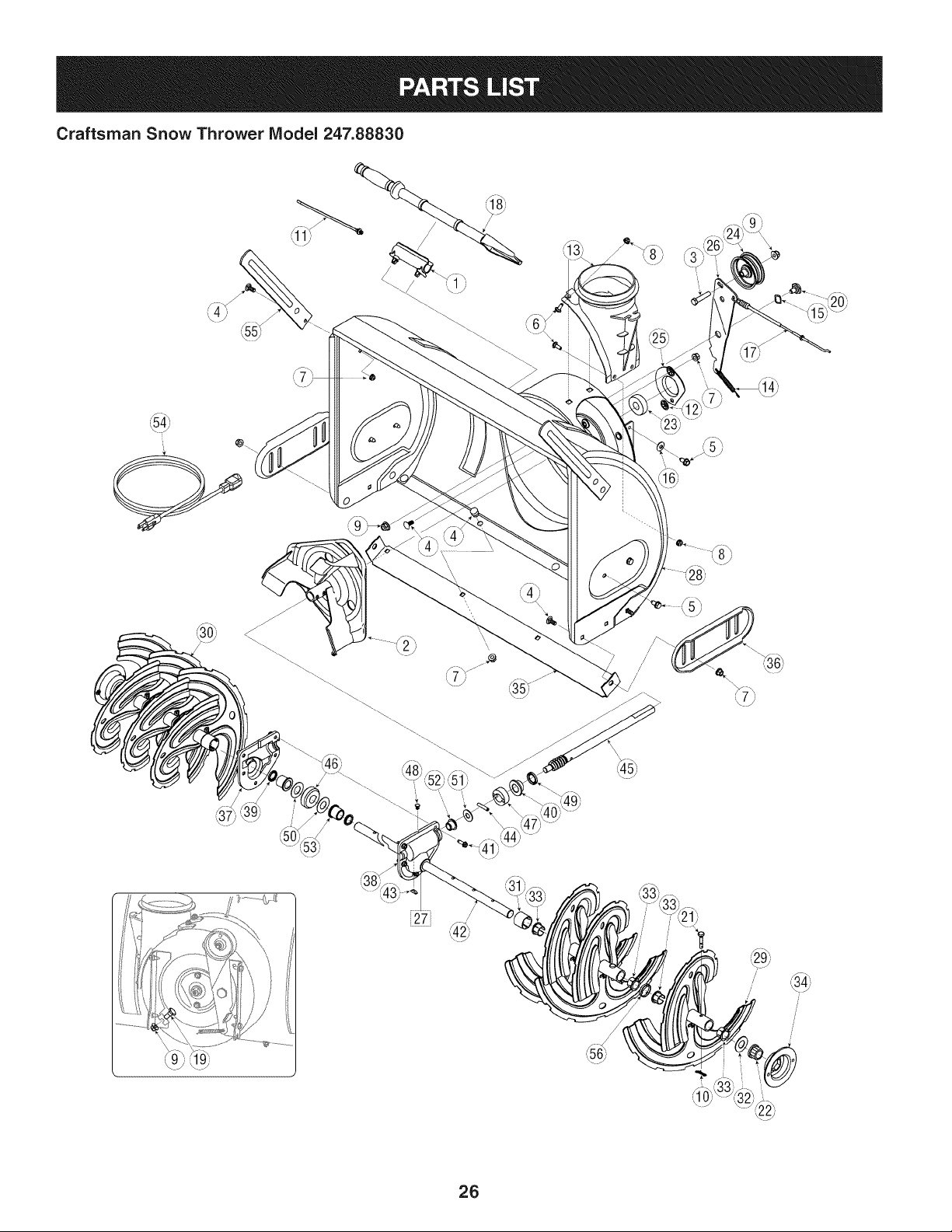
Craftsman Snow Thrower IViodel 247.88830
i27j
/
/
@
/
!
,/
/
26
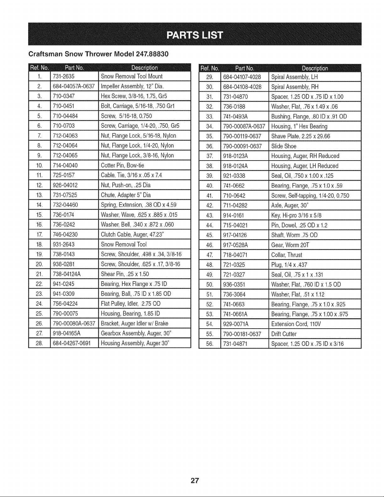
Craftsman Snow Thrower IViodel 247.88830
D = 0 0
731-2635 SnowRemovalToolMount
2. 684-04057A-0637 ImpellerAssembly,12"Dia.
3. L710-0347 LHexScrew,3/8-16, 1.75,Gr5
4. 710-0451 Bolt,Carriage,5/16-18,.750Grl
5. 710-04484 Screw, 5/16-18,0.750
6. 710-0703 Screw,Carriage,1/4-20,.750,Gr5
7. 712-04063 Nut, FlangeLock,5/16-18,Nylon
8. 712-04064 Nut, FlangeLock,1/4-20,Nylon
9. 712-04065 Nut, FlangeLock,3/8-16,Nylon
10. 714-04040 CotterPin,Bow-tie
11. 725-0157 Cable,Tie, 3/16x .05x 7.4
12. 926-04012 Nut, Push-on,.25 Dia
13. 731-07525 Chute,Adapter5" Dia
14. 732-04460 Spring,Extension,.38ODx 4.59
15. 736-0174 Washer,Wave,.625x .885x .015
16. 736-0242 Washer,Bell, .340x .872x .060
17. 746-04230 ClutchCable,Auger,47.23"
18. 931-2643 SnowRemovalTool
19. .738-0143 J Screw,Shoulder,.498x .34,3/8-16
20. 938-0281 Screw,Shoulder,.625x .17,3/8-16
21. 738-04124A ShearPin, .25x 1.50
22. 941-0245 Bearing,HexFlangex .75ID
23. 941-0309 Bearing,Ball,.75 ID x 1.85OD
24. 756-04224 FlatPulley,Idler, 2.75OD
25. 790-00075 Housing,Bearing,1.85ID
26. 790-00080A-0637 Bracket,Auger Idlerw/ Brake
27. J 918-04165A . GearboxAssembly,Auger,30"
28. 684-04267-0691 HousingAssembly,Auger30"
D = O O
SpiralAssembly,LH
30. SpiralAssembly,RH
31. Spacer,1.25OD x .75ID x 1.00
32. Washer,Flat,.76x 1.49x .06
33. Bushing,Flange,.80ID x .91OD
34. Housing,1"HexBearing
684-04107-4028
684-04108-4028
731-04870
736-0188
741-0493A
790-00087A-0637
35. 790-00119-0637
36. 790-00091-0637
37. 918-0123A
38. 918-0124A
39. 921-0338
40. 741-0662
41. 710-0642
42. 711-04282
ShavePlate,2.25 x 29.66
SlideShoe
Housing,Auger,RH Reduced
Housing,Auger,LH Reduced
Seal,Oil, .750x 1.00x .125
Bearing,Flange,.75x 1.0x .59
Screw,Self-tapping,1/4-20,0.750
Axle,Auger,30"
43. 914-0161 Key,Hi-pro3/16x 5/8
44. 715-04021 Pin, Dowel,.25 ODx 1.2
45. 917-04126 Shaft,Worm.75OD
46. 917-0528A Gear,Worm20T
47. 718-04071 Collar,Thrust
48. 721-0325 Plug, 1/4x .437
49. 721-0327 Seal,Oil, .75x 1x .131
50. 936-0351 Washer,Flat,.760ID x 1.50D
51. 736-3084 Washer,Flat,.51x 1.12
52. 741-0663 Bearing,Flange,.75x 1.0x .925
53. 741-0661A Bearing,Flange,.75x 1.00x .975
54. 929-0071A ExtensionCord, 110V
55. 790-00181-0637 Drift Cutter
56. 731-04871 Spacer,1.25OD x .75ID x 3/16
27
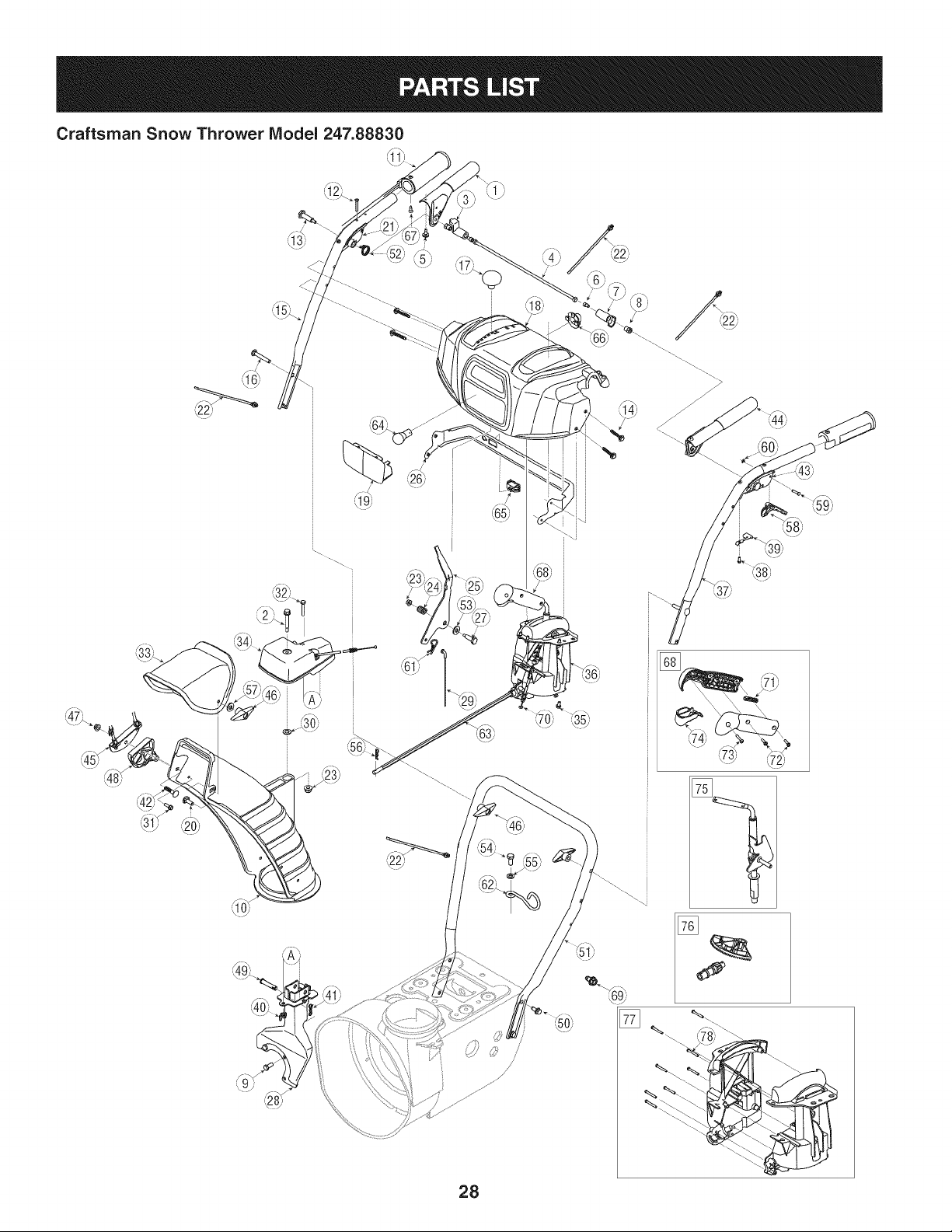
Craftsman Snow Thrower IViodel 247.88830
/ _
<
!
>
28
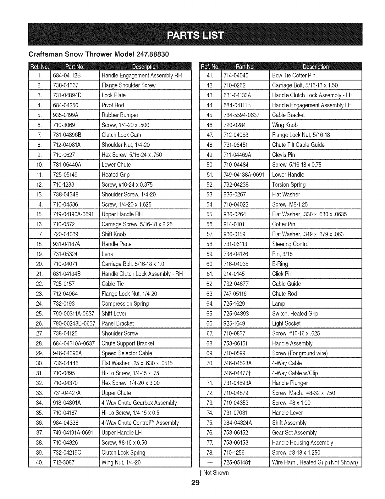
Craftsman Snow Thrower IViodel 247.88830
|= 0 =
684-04112B HandleEngagementAssemblyRH
2. 738-04367 FlangeShoulderScrew
3. 731-04894D LockPlate
4. 684-04250 PivotRod
5. 935-0199A RubberBumper
6. 710-3069 Screw,1/4-20x .500
7. 731-04896B ClutchLock Cam
8. 712-04081A ShoulderNut, 1/4-20
9. 710-0627 HexScrew,5/16-24x .750
10. 731-06440A LowerChute
11. 725-05149 HeatedGrip
12. 710-1233 Screw,#10-24x 0.375
13. 738-04348 ShoulderScrew,1/4-20
14. 710-04586 Screw,1/4-20x 1.625
15. 749-04190A-0691 UpperHandleRH
16. 710-0572 CarriageScrew,5/16-18x 2.25
17. 720-04039 Shift Knob
18. 931-04187A HandlePanel
19. 731-05324 Lens
20. 710-04071 CarriageBolt,5/16-18x 1.0
21. 631-04134B HandleClutchLockAssembly- RH
22. 725-0157 CableTie
23. 712-04064 FlangeLockNut, 1/4-20
24. 732-0193 CompressionSpring
25. 790-00311A-0637 Shift Lever
26. 790-00248B-0637 PanelBracket
27. 738-04125 ShoulderScrew
28. 684-04310A-0637 ChuteSupportBracket
29. 946-04396A SpeedSelectorCable
30. 736-04446 FiatWasher,.25x .630x .0515
31. 710-0895 Hi-LoScrew,1/4-15x .75
32. 710-04370 HexScrew,1/4-20x 3.00
33. 731-04427A UpperChute
34. 918-04801A 4-WayChuteGearboxAssembly
35. 710-04187 Hi-LoScrew,1/4-15x 0.5
36. 984-04338 4-WayChuteControlTM Assembly
37. 749-04191A-0691 UpperHandleLH
38. 710-04326 Screw,#8-16x 0.50
39. 732-04219C ClutchLockSpring
40. 712-3087 Wing Nut,1/4-20
D = O 0
714-04040 BowTie CotterPin
42. 710-0262 CarriageBolt,5/16-18x 1.50
43. 631-04133A HandleClutchLockAssembly- LH
44. 684-04111B HandleEngagementAssemblyLH
45. 784-5594-0637 Cable Bracket
46. 720-0284 Wing Knob
47. 712-04063 FlangeLockNut,5/16-18
48. 731-06451 ChuteTilt CableGuide
49. 711-04469A ClevisPin
50. 710-04484 Screw,5/16-18x 0.75
51. 749-04138A-0691 LowerHandle
52. 732-04238 TorsionSpring
53. 936-0267 FiatWasher
54. 710-04022 Screw,M8-1.25
55. 936-0264 FiatWasher,.330x .630x .0635
56. 914-0101 CotterPin
57. 936-0159 FiatWasher,.349x .879x .063
58. 731-06113 SteeringControl
59. 738-04126 Pin,3/16
60. 716-04036 E-Ring
61. 914-0145 Click Pin
62. 732-04677 CableGuide
63. 747-05116 ChuteRod
64. 725-1629 Lamp
65. 725-04393 Switch,HeatedGrip
66. 925-1649 LightSocket
67. 710-0837 Screw,#10-16x .625
68. 753-06151 HandleAssembly
69. 710-0599 Screw (Forgroundwire)
74. 731-07031 HandleLever
75. 984-04324A ShiftAssembly
76. 753-06152 GearSetAssembly
77. 753-06153 HandleHousingAssembly
78. 710-1256 Screw,#8-18x 1.250
-- 725-05148t Wire Harn.,HeatedGrip(Not Shown)
1 NotShown
29
70. 746-04528A 4-WayCable
746-044771- 4-WayCablew/Clip
71. 731-04893A HandlePlunger
72. 710-04879 Screw,Mach.,#8-32 x .750
73. 710-04353 Screw,#8 x 1.00
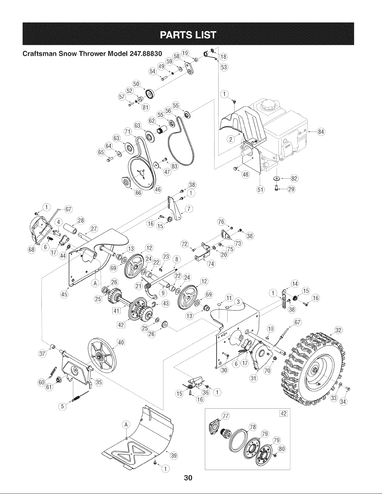
Craftsman Snow Thrower IViodel 247.88830 _.._,=_ _ -'-_,
_49__ "_ _53)
¢_
__ ,(761
3O
)
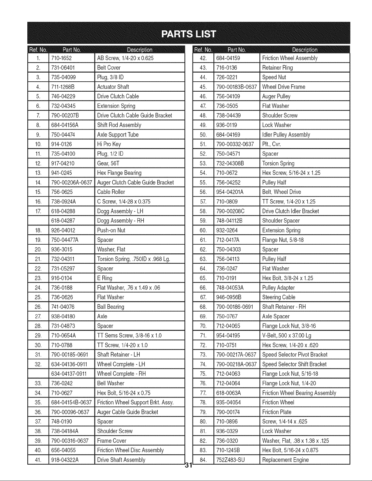
D_i BO¸
710-1652 AB Screw,1/4-20x 0.625
2. 731-06401 BeltCover
3. 735-04099 Plug,3/8 ID
4. 711-1268B ActuatorShaft
5. 746-04229 DriveClutchCable
6. 732-04345 ExtensionSpring
7. 790-00207B DriveClutchCableGuideBracket
8. 684-04156A ShiftRodAssembly
9. 750-04474 AxleSupportTube
10. 914-0126 Hi Pro Key
11. 735-04100 Plug,1/2 ID
12. 917-04210 Gear,56T
13. 941-0245 Hex FlangeBearing
14. 790-00206A-0637 AugerClutchCableGuideBracket
15. 756-0625 CableRoller
16. 738-0924A C Screw,1/4-28x 0.375
17. 618-04288 DoggAssembly- LH
618-04287 DoggAssembly- RH
18. 926-04012 Push-onNut
19. 750-04477A Spacer
20. 936-3015 Washer,Fiat
21. 732-04311 TorsionSpring,.7501Dx .968 Lg.
22. 731-05297 Spacer
23. 916-0104 E Ring
24. 736-0188 FiatWasher,.76x 1.49x .06
25. 736-0626 FiatWasher
26. 741-04076 BallBearing
27. 938-04180 Axle
28. 731-04873 Spacer
29. 710-0654A TTSeresScrew,3/8-16x 1.0
30. 710-0788 TTScrew,1/4-20x 1.0
31. 790-00185-0691 ShaftRetainer- LH
32. 634-04136-0911 WheelComplete-LH
634-04137-0911 WheelComplete-RH
33. 736-0242
34. 710-0627
35. 684-04154B-0637
36. 790-00096-0637
3_ 748-0190
38. 738-04184A
39. 790-00316-0637
40. 656-04055
41. 918-04322A
BellWasher
HexBolt,5/16-24x 0.75
FrictionWheelSupportBrkt.Assy.
AugerCableGuideBracket
Spacer
ShoulderScrew
FrameCover
FrictionWheelDiscAssembly
DriveShaftAssembly
31
m _ O
684-04159 FrictionWheelAssembly
43. 716-0136 RetainerRing
44. 726-0221 SpeedNut
45. 790-00183B-0637 WheelDrive Frame
46. 756-04109 AugerPulley
47. 736-0505 FiatWasher
48. 738-04439 ShoulderScrew
49. 936-0119 LockWasher
50. 684-04169 IdlerPulleyAssembly
51. 790-00332-0637 Pit.,Cvr.
52. 750-04571 Spacer
53. 732-04308B TorsionSpring
54. 710-0672 HexScrew,5/16-24x 1.25
55. 756-04252 PulleyHalf
56. 954-04201A Belt,WheelDrive
57. 710-0809 TT Screw,1/4-20x 1.25
58. 790-00208C DriveClutchIdlerBracket
59. 748-04112B ShoulderSpacer
60. 932-0264 ExtensionSpring
61. 712-0417A FlangeNut,5/8-18
62. 750-04303 Spacer
63. 756-04113 PulleyHalf
64. 736-0247 FiatWasher
65. 710-0191 HexBolt,3/8-24x 1.25
66. 748-04053A PulleyAdapter
67. 946-0956B SteeringCable
68. 790-00186-0691 ShaftRetainer- RH
69. 750-0767 Axle Spacer
70. 712-04065 FlangeLock Nut,3/8-16
71. 954-04195 V-Belt,.500x 37.00Lg
72. 710-0751 HexScrew,1/4-20x .620
73. 790-00217A-0637 SpeedSelectorPivotBracket
74. 790-00218A-0637 SpeedSelectorShiftBracket
75. 712-04063 FlangeLock Nut,5/16-18
76. 712-04064 FlangeLock Nut, 1/4-20
77. 618-0063A FrictionWheelBearingAssembly
78. 935-04054 FrictionWheel
79. 790-00174 FrictionPlate
80. 710-0896 Screw,1/4-14x .625
81. 936-0329 LockWasher
82. 736-0320 Washer,Fiat,.38x 1.38x .125
83. 710-1245B HexBolt,5/16-24x 0.875
84. 752Z483-SU ReplacementEngine
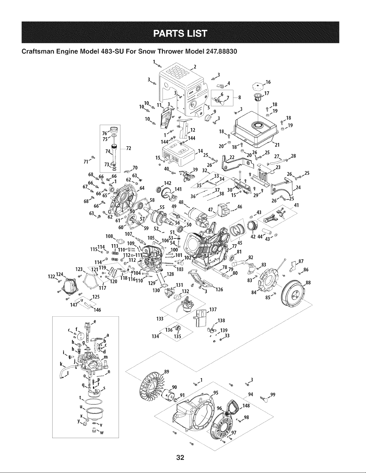
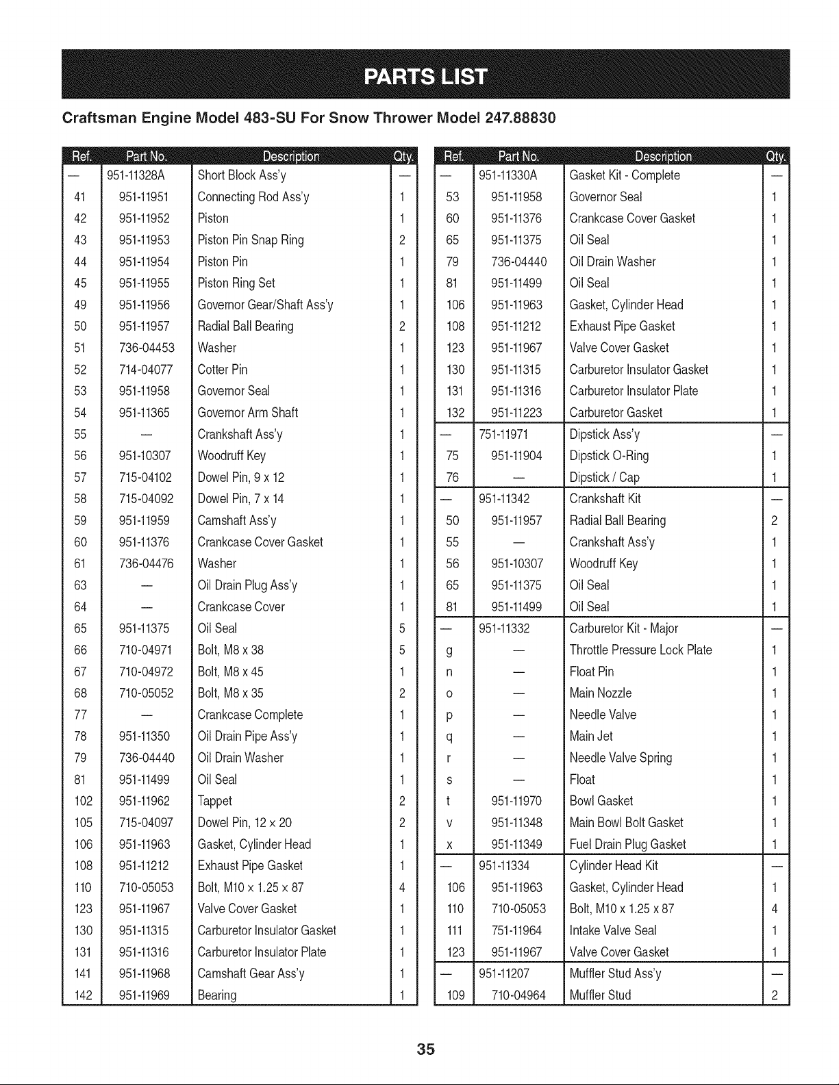
Craftsman Engine Model 483=SU For Snow Thrower Model 247.88830
99
32
Craftsman Engine IViodel 483-SU For Snow Thrower IViodel 247.88830
m
1
2
3
4
5
7
8
9
10
11
12
14
15
16
17
18
19
2O
21
22
23
24
25
26
28
29
30
33
34
35
36
37
38
39
40
41
42
43
44
710-11012
951-11339
710-04915
951-10757
951-11595
731-05632
951-10637
951-11302
710-04914
951-11181
951-11321
951-11338
712-04219
951-10649
951-11933
710-04970
750-05312
750-05313
951-11201
951-11319
951-11318
951-11351
951-11012
736-04452
951-11731
710-04921
951-11182
712-04212
710-04908
951-11307
951-11306
951-11203
951-11309
951-11311
710-04916
951-11951
951-11952
951-11953
951-11954
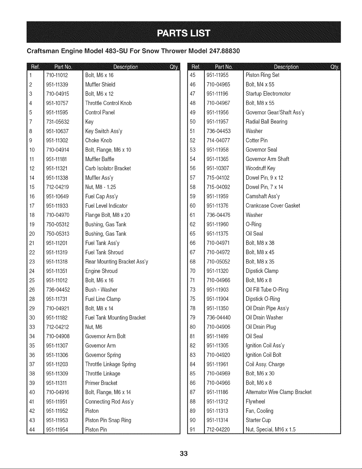
|= o o e
Bolt,M6x 16
MufflerShield
Bolt,M6x 12
ThrottleControlKnob
ControlPanel
Key
KeySwitchAss'y
ChokeKnob
Bolt,Flange,M6x 10
MufflerBaffle
CarbIsolatorBracket
MufflerAss'y
Nut, M8- 1.25
FuelCapAss'y
FuelLevelIndicator
FlangeBolt,M8x 20
Bushing,Gas Tank
Bushing,Gas Tank
FuelTankAss'y
FuelTankShroud
RearMountingBracketAss'y
EngineShroud
Bolt,M6x 16
Bush- Washer
FuelLineClamp
Bolt,M8x 14
FuelTankMountingBracket
Nut, M6
GovernorArm Bolt
GovernorArm
GovernorSpring
ThrottleLinkageSpring
ThrottleLinkage
PrimerBracket
Bolt,Flange,M6x 14
ConnectingRodAss'y
Piston
PistonPinSnapRing
PistonPin
m
45
46
47
48
49
5O
51
52
53
54
56
57
58
59
6O
61
62
65
66
67
68
70
71
73
75
78
79
80
81
82
83
84
85
86
87
88
89
90
91
951-11955
710-04965
951-11196
710-04967
951-11956
951-11957
736-04453
714-04077
951-11958
951-11365
951-10307
715-04102
715-04092
951-11959
951-11376
736-04476
951-11960
951-11375
710-04971
710-04972
710-05052
951-11320
710-04966
951-11903
951-11904
951-11350
736-04440
710-04906
951-11499
951-11305
710-04920
951-11961
710-04969
710-04966
951-11186
951-11312
951-11313
951-11314
712-04220
|= 0 e e
PistonRingSet
Bolt,M4x 55
StartupElectromotor
Bolt,M8x 55
GovernorGear/ShaftAss'y
RadialBall Bearing
Washer
CotterPin
GovernorSeal
GovernorArmShaft
WoodruffKey
DowelPin,9 x 12
DowelPin,7x 14
CamshaftAss'y
CrankcaseCoverGasket
Washer
O-Ring
Oil Seal
Bolt,M8x 38
Bolt,M8x 45
Bolt,M8x 35
DipstickClamp
Bolt,M6x 8
Oil FillTubeO-Ring
DipstickO-Ring
Oil DrainPipeAss'y
Oil DrainWasher
Oil DrainPlug
Oil Seal
IgnitionCoil Ass'y
IgnitionCoil Bolt
Coil Assy.Charge
Bolt,M6x 30
Bolt,M6x 8
AlternatorWire ClampBracket
Flywheel
Fan,Cooling
StarterCup
Nut,Special,M16x 1.5
33
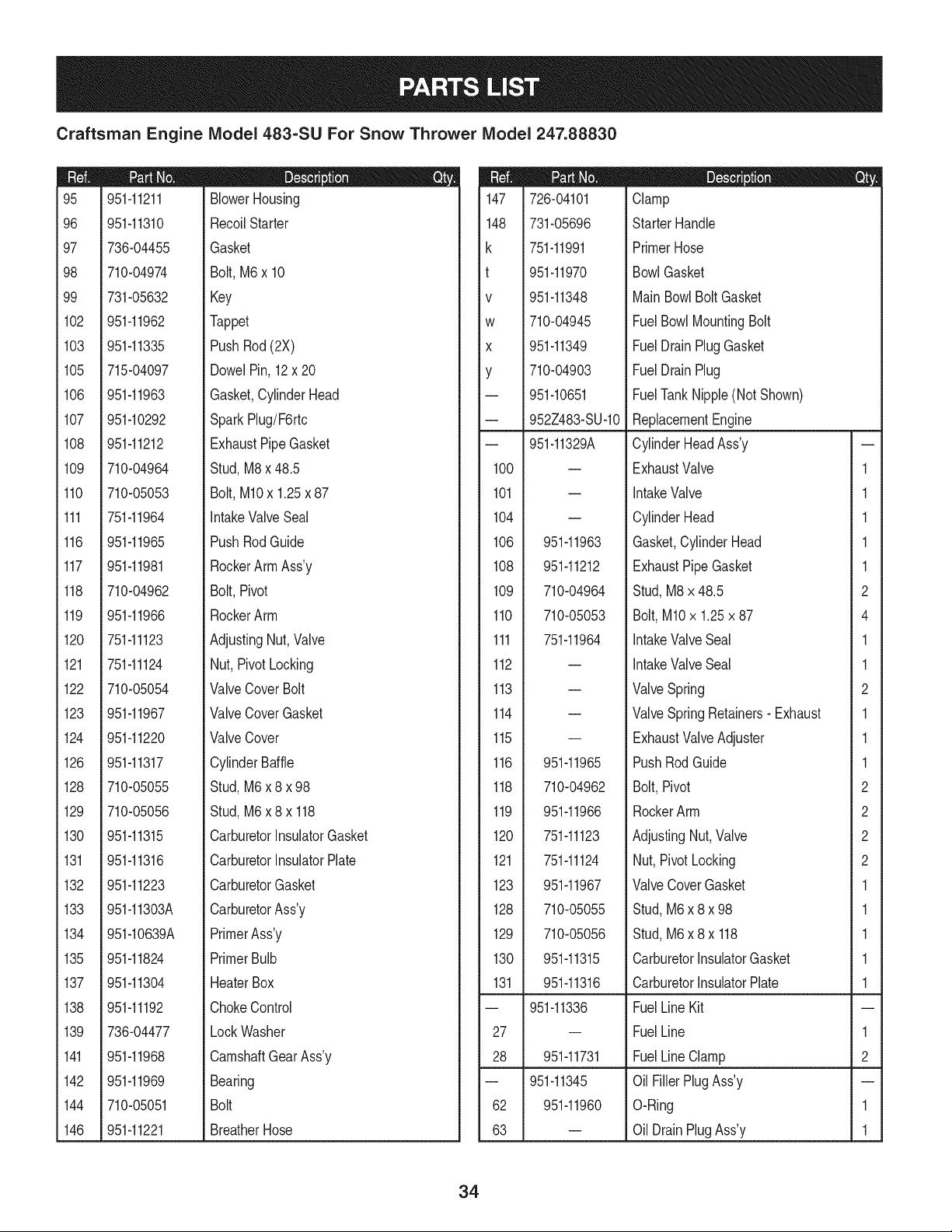
Craftsman Engine Model 483-SU For Snow Thrower Model 247.88830
m
95
96
97
98
99
102
103
105
106
107
108
109
110
111
116
117
118
119
120
121
122
123
124
126
128
129
130
131
132
133
134
135
137
138
139
141
142
144
146
951-11211
951-11310
736-04455
710-04974
731-05632
951-11962
951-11335
715-04097
951-11963
951-10292
951-11212
710-04964
710-05053
751-11964
951-11965
951-11981
710-04962
951-11966
751o11123
751-11124
710-05054
951-11967
951-11220
951-11317
710-05055
710-05056
951-11315
951-11316
951-11223
951-11303A
951-10639A
951-11824
951-11304
951-11192
736-04477
951-11968
951-11969
710-05051
951-11221
|- 0 e e
BlowerHousing
RecoilStarter
Gasket
Bolt,M6 x 10
Key
Tappet
PushRod(2X)
DowelPin, 12x 20
Gasket,CylinderHead
SparkRug/F6rtc
ExhaustPipeGasket
Stud,M8x 48.5
Bolt,M10x 1.25x 87
IntakeValveSeal
PushRodGuide
RockerArmAss'y
Bolt,Pivot
RockerArm
AdjustingNut,Valve
Nut, PivotLocking
ValveCover Bolt
ValveCoverGasket
ValveCover
CylinderBaffle
Stud,M6x 8 x 98
Stud,M6x8x 118
CarburetorInsulatorGasket
CarburetorInsulatorPlate
CarburetorGasket
CarburetorAss'y
PrimerAss'y
PrimerBulb
HeaterBox
ChokeControl
LockWasher
CamshaftGearAss'y
Bearing
Bolt
BreatherHose
|= o _ e
147 726-04101 Clamp
148 731-05696 StarterHandle
k 751-11991 PrimerHose
t 951-11970 BowlGasket
v 951-11348 MainBowlBoltGasket
w 710-04945 FuelBowlMountingBolt
x 951-11349 FuelDrainPlugGasket
y 710-04903 FuelDrainPlug
-- 951-10651 FuelTankNipple(Not Shown)
-- 952Z483-SU-10 ReplacementEngine
-- 951-11329A CylinderHeadAss'y
100 -- ExhaustValve 1
101 -- IntakeValve 1
104 -- CylinderHead 1
106 951-11963 Gasket,CylinderHead 1
108 951-11212 ExhaustPipeGasket 1
109 710-04964 Stud,M8 x 48.5 2
110 710-05053 Bolt,M10x 1.25x 87 4
111 751-11964 IntakeValveSeal 1
112 -- IntakeValveSeal 1
113 -- ValveSpring 2
114 -- ValveSpringRetainers- Exhaust 1
115 -- ExhaustValveAdjuster 1
116 951-11965 PushRodGuide 1
118 710-04962 Bolt,Pivot 2
119 951-11966 RockerArm 2
120 751-11123 AdjustingNut,Valve 2
121 751-11124 Nut,PivotLocking 2
123 951-11967 ValveCoverGasket 1
128 710-05055 Stud,M6 x 8 x 98 1
129 710-05056 Stud,M6 x 8 x 118 1
130 951-11315 CarburetorInsulatorGasket 1
131 951-11316 CarburetorInsulatorPlate 1
-- 951-11336 FuelLine Kit
27 -- FuelLine 1
28 951-11731 FuelLine Clamp 2
-- 951-11345 Oil FillerPlugAss'y
62 951-11960 O-Ring 1
63 -- OilDrainPlugAss'y 1
34
Craftsman Engine IViodel 483=SU For Snow Thrower IViodel 247.88830
m
41
42
43
44
45
49
5O
51
52
53
54
55
56
57
58
59
6O
61
63
64
65
66
67
68
77
78
79
81
102
105
106
108
110
123
130
131
141
142
951-11328A
951-11951
951-11952
951-11953
951-11954
951-11955
951-11956
951-11957
736-04453
714-04077
951-11958
951-11365
951-10307
715-04102
715-04092
951-11959
951-11376
736-04476
m
951-11375
710-04971
710-04972
710-05052
951-11350
736-04440
951-11499
951-11962
715-04097
951-11963
951-11212
710-05053
951-11967
951-11315
951-11316
951-11968
951-11969
D = O O
ShortBlockAss'y
ConnectingRodAss'y
Piston
PistonPinSnapRing
PistonPin
PistonRingSet
GovernorGear/ShaftAss'y
RadialBallBearing
Washer
CotterPin
GovernorSeal
GovernorArm Shaft
CrankshaftAss'y
WoodruffKey
DowelPin,9 x 12
DowelPin,7 x 14
CamshaftAss'y
CrankcaseCoverGasket
Washer
Oil DrainPlugAss'y
CrankcaseCover
OilSeal
Bolt,M8x 38
Bolt,M8x 45
Bolt,M8x 35
CrankcaseComplete
Oil DrainPipeAss'y
Oil DrainWasher
OilSeal
Tappet
DowelPin, 12x 20
Gasket,CylinderHead
ExhaustPipeGasket
Bolt,M10x 1.25x 87
ValveCoverGasket
CarburetorInsulatorGasket
CarburetorInsulatorPlate
CamshaftGearAss'y
Bearing
m
1
1
2
1
1
1
2
1
1
1
1
1
1
1
1
1
1
1
1
1
5
5
1
2
1
1
1
1
2
2
1
1
4
1
1
1
1
1
m = O O
-- 951-11330A GasketKit- Complete
53 951-11958 GovernorSeal 1
60 951-11376 CrankcaseCoverGasket 1
65 951-11375 Oil Seal 1
79 736-04440 Oil DrainWasher 1
81 951-11499 Oil Seal 1
106 951-11963 Gasket,CylinderHead 1
108 951-11212 ExhaustPipeGasket 1
123 951-11967 ValveCoverGasket 1
130 951-11315 CarburetorinsulatorGasket 1
131 951-11316 CarburetorinsulatorPlate 1
132 951-11223 CarburetorGasket 1
-- 751-11971 DipstickAss'y
75 951-11904 DipstickO-Ring 1
76 -- Dipstick/ Cap 1
-- 951-11342 CrankshaftKit
50 951-11957 RadialBallBearing 2
55 -- CrankshaftAss'y 1
56 951-10307 WoodruffKey 1
65 951-11375 Oil Seal 1
81 951-11499 Oil Seal 1
-- 951-11332 CarburetorKit- Major
g -- ThrottlePressureLockPlate 1
n -- FloatPin 1
o -- MainNozzle 1
p -- NeedleValve 1
q -- MainJet 1
r -- NeedleValveSpring 1
s -- Float 1
t 951-11970 BowlGasket 1
v 951-11348 MainBowlBolt Gasket 1
x 951-11349 FuelDrainPlugGasket 1
-- 951-11334 CylinderHeadKit
106 951-11963 Gasket,CylinderHead 1
110 710-05053 Bolt,M10x 1.25x 87 4
111 751-11964 IntakeValveSeal 1
123 951-11967 ValveCoverGasket 1
-- 951-11207 MufflerStudAss'y
109 710-04964 MufflerStud 2
35
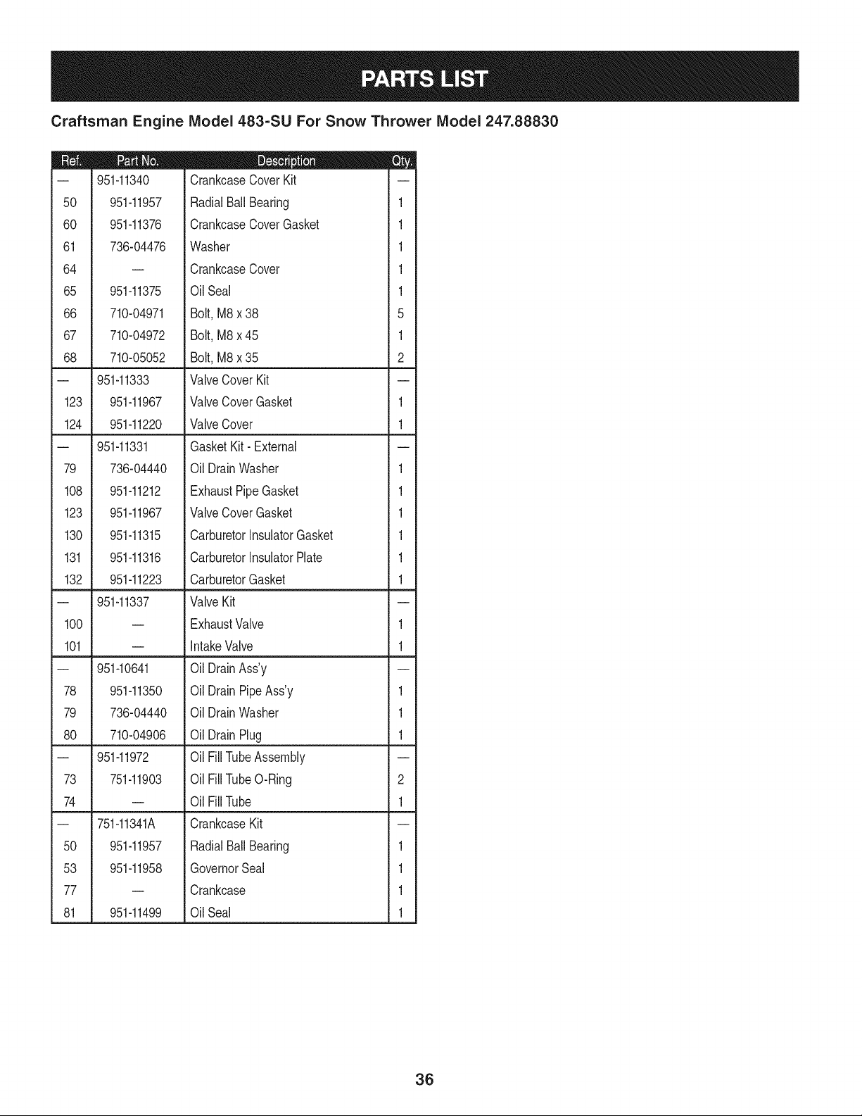
Craftsman Engine IViodel 483=SU For Snow Thrower IViodel 247.88830
D = O O
-- 951-11340 CrankcaseCoverKit
50 951-11957 RadialBall Bearing 1
60 951-11376 CrankcaseCoverGasket 1
61 736-04476 Washer 1
64 -- CrankcaseCover 1
65 951-11375 Oil Seal 1
66 710-04971 Bolt, M8 x 38 5
67 710-04972 Bolt, M8 x 45 1
68 710-05052 Bolt, M8 x 35 2
-- 951-11333 ValveCover Kit
123 951-11967 ValveCoverGasket 1
124 951-11220 ValveCover 1
-- 951-11331 GasketKit- External
79 736-04440 Oil DrainWasher 1
108 951-11212 ExhaustPipeGasket 1
123 951-11967 ValveCoverGasket 1
130 951-11315 CarburetorInsulatorGasket 1
131 951-11316 CarburetorInsulatorPlate 1
132 951-11223 CarburetorGasket 1
-- 951-11337 ValveKit
100 -- ExhaustValve 1
101 -- intakeValve 1
-- 951-10641 Oil DrainAss'y
78 951-11350 Oil DrainPipeAss'y 1
79 736-04440 Oil DrainWasher 1
80 710-04906 Oil DrainPlug 1
-- 951-11972 Oil FillTubeAssembly
73 751-11903 Oil FillTubeO-Ring 2
74 -- Oil FillTube 1
-- 751-11341A CrankcaseKit
50 951-11957 RadialBall Bearing 1
53 951-11958 GovernorSeal 1
77 -- Crankcase 1
81 951-11499 Oil Seal 1
36
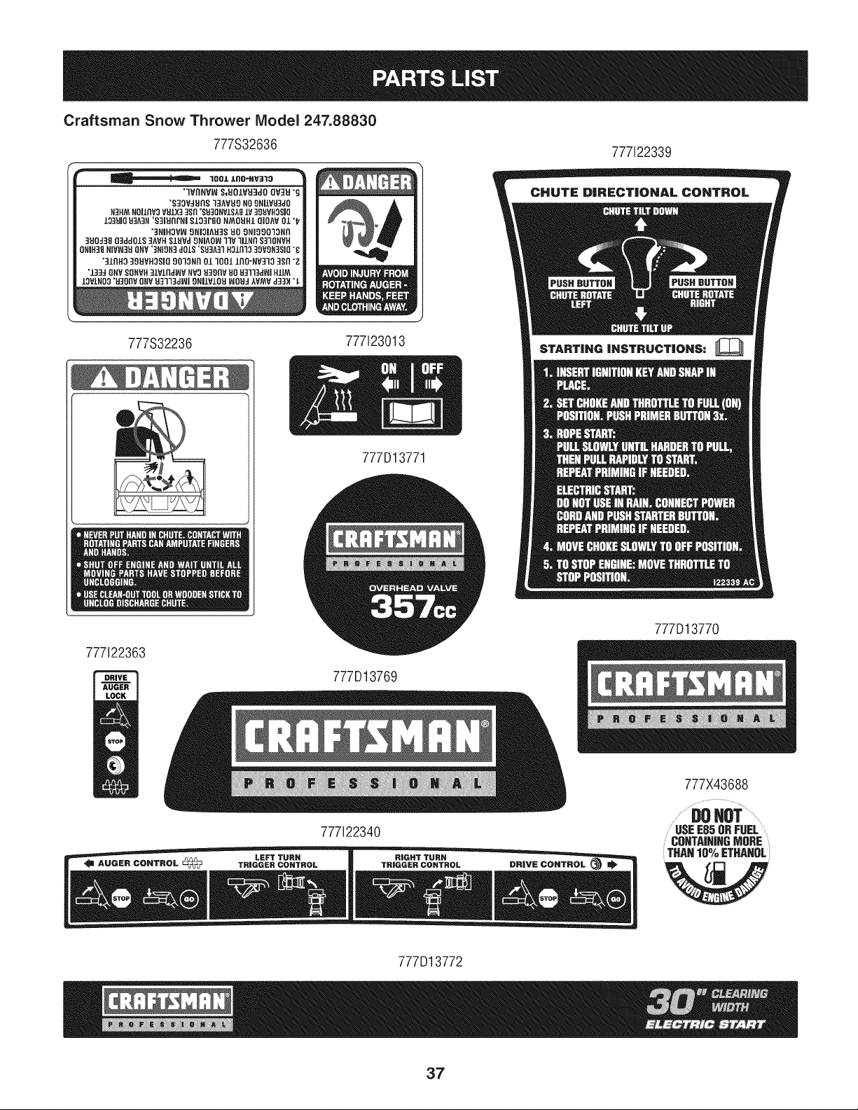
Craftsman Snow Thrower IVlodel 247.88830
777S32636
1001 lnO-I_V31,0
'IVnNVIN 8,UOIVU3dO QV_]EI"_
'8]OVdBn8 "I]AVH_) NO9NilVB3dO
N3HM NOilnV3 VB.LX33sn 'SB3QNVIStBIV 39BVHOSJO
133B10B3A::IN'S3IUNFNI $I0_r80 NMOBHI QIOAV Ol 't_
"3NIH3V_I 9NIOIAU38 BO 9NiOgOlONn
]BOd31] 03ddOlS ]AVH SIBVd 9NIAO_I llV liINn S31QNVH
QNiH38 NIVI/,J3BQNV '3NION3dOIS 'SB3A31 HOlnlO 3OVON]SiO "8
';]lriH3]gBVHO$1Q_OlONnOZ10011nO-NV3103Sn"Z
'1_3:1 QNV SQNVH31VlndVJV NVOB39ffV UO B3113d_l HIiM
10VINO0 'B]911V ONVB3]13dl_l 9NilVIOB WOU::IAVMV d3]H 7-
777S32236
777123013
777i22339
STARTING iNSTRUCTiONS:
777D13771
777122363
777D13769
777D13770
777122340
777X43688
DOHOT.........
USEE85ORFUEL
COHTAiHIHGMORE
THAN 10% ETHANOL
777D13772
37
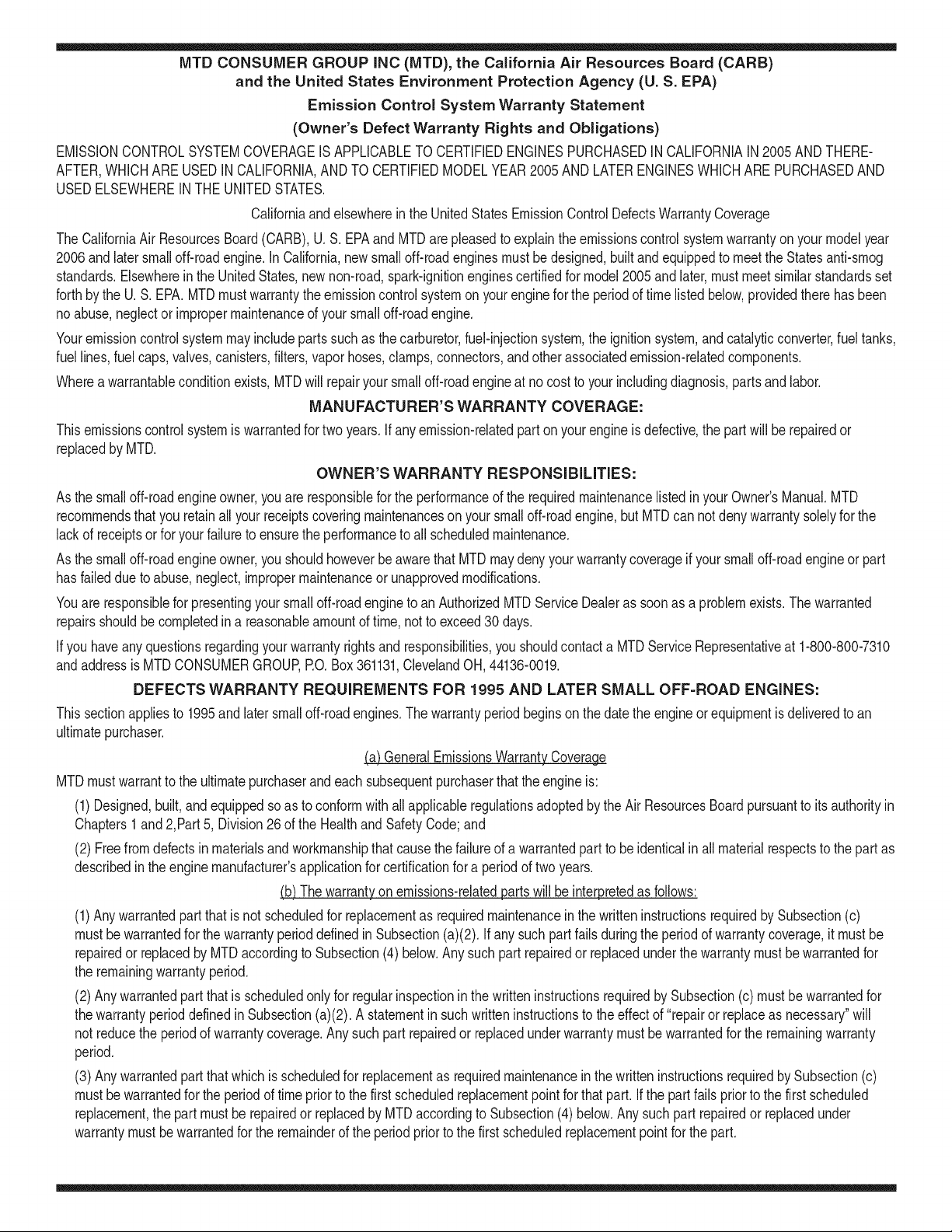
MTD CONSUMER GROUP INC (MTD), the California Air Resources Board (CARB)
and the United States Environment Protection Agency (U. S. EPA)
Emission Control System Warranty Statement
(Owner's Defect Warranty Rights and Obligations)
EMISSIONCONTROLSYSTEMCOVERAGEIS APPLICABLETOCERTIFIEDENGINESPURCHASEDINCALIFORNIAIN2005ANDTHERE-
AFTER,WHICHARE USEDIN CALIFORNIA,ANDTO CERTIFIEDMODELYEAR2005 AND LATERENGINESWHICHARE PURCHASEDAND
USEDELSEWHEREIN THE UNITEDSTATES.
Californiaand elsewherein the UnitedStatesEmissionControlDefectsWarrantyCoverage
The CaliforniaAir ResourcesBoard(CARB),U.S. EPAand MTDare pleasedto explaintheemissionscontrol systemwarrantyon your modelyear
2006andlatersmalloff-roadengine.In California,new smalloff-roadenginesmustbe designed,builtand equippedto meettheStatesanti-smog
standards.Elsewhereinthe UnitedStates,newnon-road,spark-ignitionenginescertifiedfor model2005and later,mustmeetsimilarstandardsset
forthby the U.S. EPA.MTDmustwarrantythe emissioncontrolsystemonyourenginefor the periodof timelistedbelow,providedtherehasbeen
noabuse,neglector impropermaintenanceof your smalloff-roadengine.
Youremissioncontrolsystemmay includepartssuch as the carburetor,fuel-injectionsystem,the ignitionsystem,andcatalyticconverter,fueltanks,
fuel lines,fuel caps,valves,canisters,filters,vaporhoses,clamps,connectors,andotherassociatedemission-relatedcomponents.
Wherea warrantableconditionexists,MTDwill repairyoursmall off-roadengineat nocost to yourincludingdiagnosis,partsand labor.
MANUFACTURER'S WARRANTY COVERAGE:
Thisemissionscontrolsystemis warrantedfor two years.If anyemission-relatedpart onyourengineis defective,the part will berepairedor
replacedby MTD.
OWNER'S WARRANTY RESPONSIBILITIES:
As the smalloff-roadengineowner,youare responsibleforthe performanceof the requiredmaintenancelisted in your Owner'sManual.MTD
recommendsthatyou retainall yourreceiptscoveringmaintenanceson yoursmalloff-roadengine,but MTDcan not denywarrantysolelyfor the
lackof receiptsor foryour failureto ensurethe performanceto all scheduledmaintenance.
As the smalloff-roadengineowner,youshouldhoweverbeawarethat MTDmaydenyyour warrantycoverageif yoursmalloff-roadengineorpart
hasfaileddue toabuse,neglect,impropermaintenanceor unapprovedmodifications.
Youare responsiblefor presentingyour smalloff-roadengineto an AuthorizedMTDServiceDealeras soonas a problemexists.Thewarranted
repairsshouldbe completedina reasonableamountof time,notto exceed30 days.
Ifyou haveanyquestionsregardingyourwarrantyrightsand responsibilities,you shouldcontacta MTDServiceRepresentativeat 1-800-800-7310
andaddressis MTDCONSUMERGROUP,RO. Box361131,ClevelandOH,44136-0019.
DEFECTS WARRANTY REQUIREMENTS FOR 1995 AND LATER SMALL OFF-ROAD ENGINES:
Thissectionappliesto 1995and later smalloff-roadengines.The warrantyperiodbeginsonthe datethe engineor equipmentis deliveredto an
ultimatepurchaser.
(a) GeneralEmissionsWarrantyCoverage
MTDmustwarrantto the ultimatepurchaserand eachsubsequentpurchaserthat the engineis:
(1)Designed,built,andequippedsoas to conformwithallapplicableregulationsadoptedby the Air ResourcesBoardpursuantto its authorityin
Chapters1and2,Part5, Division26of the Healthand SafetyCode;and
(2) Freefrom defectsin materialsand workmanshipthatcausethe failureof a warrantedpart to beidenticalin all materialrespectsto the partas
describedin theenginemanufacturer'sapplicationfor certificationfora periodof two years.
(b)The warrantyonemissions-relatedpartswill be interpretedas follows:
(1)Anywarrantedpart thatis not scheduledfor replacementas requiredmaintenanceinthe writteninstructionsrequiredby Subsection(c)
mustbewarrantedfor the warrantyperioddefinedin Subsection(a)(2). If any suchpartfailsduringthe periodof warrantycoverage,it mustbe
repairedor replacedby MTDaccordingto Subsection(4) below.Anysuch part repairedor replacedunder thewarrantymustbe warrantedfor
the remainingwarrantyperiod.
(2)Any warrantedpartthat is scheduledonlyfor regularinspectionin the writteninstructionsrequiredby Subsection(c) must bewarrantedfor
thewarrantyperioddefinedin Subsection(a)(2).A statementinsuchwritteninstructionsto the effectof "repairor replaceas necessary"will
not reducethe periodof warrantycoverage.Anysuch part repairedor replacedunderwarrantymustbe warrantedforthe remainingwarranty
period.
(3) Anywarrantedpartthat whichis scheduledfor replacementas requiredmaintenancein the writteninstructionsrequiredby Subsection(c)
mustbewarrantedfor the periodof time prior to the first scheduledreplacementpointforthat part.Ifthe part failspriorto thefirst scheduled
replacement,the part mustbe repairedor replacedby MTDaccordingto Subsection(4) below.Any such part repairedor replacedunder
warrantymustbewarrantedfor the remainderof the periodpriorto the first scheduledreplacementpointfor the part.
(4)Repairorreplacementofanywarrantedpartunderthewarrantyprovisionsofthisarticlemustbeperformedatnochargetotheownerata
warrantystation.
(5)NotwithstandingtheprovisionsofSubsection(4)above,warrantyservicesorrepairsmustbeprovidedatallMTDdistributioncentersthat
arefranchisedtoservicethesubjectengines.
(6)Theownermustnotbechargedfordiagnosticlaborthatleadstothedeterminationthatawarrantedpartisinfactdefective,providedthat
suchdiagnosticworkisperformedatawarrantystation.
(7)Theenginemanufacturerisliablefordamagestootherenginecomponentsproximatelycausedbyafailureunderwarrantyofanywarranted
part.
(8)Throughouttheengine'swarrantyperioddefinedinSubsection(a)(2),MTDwillmaintainasupplyofwarrantedpartssufficienttomeetthe
expecteddemandforsuchparts.
(9)Anyreplacementpartmaybeusedintheperformanceofanywarrantymaintenanceorrepairsandmustbeprovidedwithoutchargetothe
owner.SuchusewillnotreducethewarrantyobligationsofMTD.
(10)Add-onormodifiedpartsthatarenotexemptedbytheAirResourcesBoardmaynotbeused.Theuseofanynon-exemptedadd-onor
modifiedpartsshallbegroundsfordisallowingawarrantyclaimmadeinaccordancewiththisarticle.Theenginemanufacturershallnotbe
liableunderthisarticletowarrantfailuresofwarrantedpartscausedbytheuseofnon-exemptedadd-onormodifiedpart.
(c) MTDwill includea copyof the followingemissionwarrantyparts list with each newengine,usingthoseportionsof the listapplicableto the
e__&gine.
(1)FuelMeteringSystem
• Coldstart enrichmentsystem(soft choke)
,,Carburetorandinternalparts
• Fuel Pump
• FuelTank
(2)Air InductionSystem
• Air cleaner
• Intakemanifold
(3) IgnitionSystem
• Sparkplug(s)
• MagnetoIgnitionSystem
(4)ExhaustSystem
Catalyticconverter
• SAI (Reedvalve)
(5) MiscellaneousItemsUsedin AboveSystem
Vacuum,temperature, position,timesensitivevalvesand switches
Connectorsand assemblies
(6) Evaporativecontrol
• Fuel Hosecertifiedfor ARBevaporativeemissionof 2006.
• Fuel HoseClamps
Tetheredfuel cap
Carboncanister
Vaporlines
GD0C-100174Rev.B
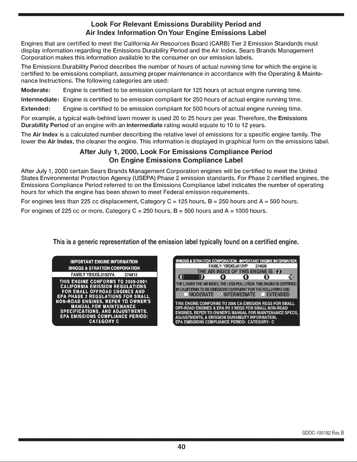
Look For Relevant Emissions Durability Period and
Air index information On Your Engine Emissions Label
Engines that are certified to meet the California Air Resources Board (CARB) Tier 2 Emission Standards must
display information regarding the Emissions Durability Period and the Air Index. Sears Brands Management
Corporation makes this information available to the consumer on our emission labels.
The Emissions Durability Period describes the number of hours of actual running time for which the engine is
certified to be emissions compliant, assuming proper maintenance in accordance with the Operating & Mainte-
nance Instructions. The following categories are used:
Moderate: Engine is certified to be emission compliant for 125 hours of actual engine running time.
Intermediate: Engine is certified to be emission compliant for 250 hours of actual engine running time.
Extended: Engine is certified to be emission compliant for 500 hours of actual engine running time.
For example, a typical walk-behind lawn mower is used 20 to 25 hours per year. Therefore, the Emissions
Durability Period of an engine with an intermediate rating would equate to 10 to 12 years.
The Air index is a calculated number describing the relative level of emissions for a specific engine family. The
lower the Air Index, the cleaner the engine. This information is displayed in graphical form on the emissions label.
After July 1,2000, Look For Emissions Compliance Period
On Engine Emissions Compliance Label
After July 1, 2000 certain Sears Brands Management Corporation engines will be certified to meet the United
States Environmental Protection Agency (USEPA) Phase 2 emission standards. For Phase 2 certified engines, the
Emissions Compliance Period referred to on the Emissions Compliance label indicates the number of operating
hours for which the engine has been shown to meet Federal emission requirements.
For engines less than 225 cc displacement, Category C = 125 hours, B = 250 hours and A = 500 hours.
For engines of 225 cc or more, Category C = 250 hours, B = 500 hours and A = 1000 hours.
This is a generic representation of the emission label typically found on a certified engine.
FAMILYYSSXS.3192VA 274812
GDOC-100182Rev.B
40
Congratulationson makinga smartpurchase.YournewCraftsman@
productis designedand manufacturedfor yearsof dependableopera-
tion.But likeall products,it may requirerepairfrom time to time.That's
whenhavinga RepairProtectionAgreementcansave youmoneyand
aggravation.
Here'swhat the RepairProtectionAgreement*includes:
* Expert service byour 10,000professionalrepairspecialists
o Unlimitedserviceand no chargefor partsand laboron all
coveredrepairs
o Product replacementupto $1500if yourcoveredproductcan't be
fixed
• Discountof 10%from regularprice of serviceand relatedinstalled
partsnotcoveredby theagreement;also, 10%off regularpriceof
preventivemaintenancecheck
• Fast help by phone- we call it RapidResolution- phonesupport
froma Searsrepresentative.Thinkof usas a "talkingowner's
manual."
Onceyou purchasethe Agreement,a simplephonecall is all thatit
takesfor youto scheduleservice.Youcan call anytimedayor night,or
schedulea serviceappointmentonline.
The RepairProtectionAgreementis a risk-freepurchase.If youcancel
for any reasonduringthe productwarrantyperiod,wewill providea full
refund.Or,a proratedrefundanytimeafter the productwarrantyperiod
expires.Purchaseyour RepairProtectionAgreementtoday!
Somelimitationsand exclusionsapply. For pricesand additional
informationin the U.S.A. call 1-800-827-6655.
*Coverage in Canadavaries on some items.Forfull details call
Sears Canadaat 1-800-361-6665.
Sears Installation Service
ForSearsprofessionalinstallationof homeappliances,garagedoor
openers,waterheaters,andothermajorhomeitems,in the U.S.A.or
Canadacall 1-800-4-MY-HOME®.
41
Declaraci6n de garantia ............................ Pagina 42
Practicas operaci6n seguras ..................... Pagina 43
Montaje ...................................................... Pagina 47
Operaci6n .................................................. Pagina 53
Servicio y Mantenimiento .......................... Pagina 58
Almacenamiento fuera de temporada ....... Pagina 65
Soluci6n de problemas .............................. Pagina 66
Acuerdo de protecci6n para reparaciones .... Pagina 71
Etiquetas de seguridad .............................. Pagina 7
Lista de piezas ........................................... Pagina 26
NOmero de servicio ................................... Cubierta
posterior
GARANTiA PROFESIONAL TOTAL CRAFTSMAN POR DOS AltOS
PORDOSANOSapartir de la fechade cornpra,este productoest&garantizadocontracualquierdefectode materialo rnanode obra.El
productodefectuosorecibir_,la reparaci6no lasustituci6ngratuitasi la reparaci6nnoest,. disponible.
Estagaranfias61otiene vigenciapot unaSodesdela fechade cornprasi esteproductosehanutilizadoalgunavez,rnientrasquela prestaci6n
de servicioscornercialeso si se alquilaa otrapersona.
Paraobtener informacibndetallada coberturade la garantiaparaobtener la reparacibno reemplazo,visite el sitio web:
www.craftsman.com
Esta garantia cubre SOLOdefectos en material y habilidad. La cobertura de garantiano incluye:
• Elernentosreutilizablesquepuedengastarsepor el uso normaldentrodel periodode garanfia,incluso,peronolirnitadospara barrenas,
barrenarernos,cortadoresde rnovirniento,patinarzapatos,platode afeitado,esquilanalfileres,bujia,filtrodeaire, cinturones,y filtrodel
aceite.
• Revisi6ndernantenirnientoest_.ndar,carnbiosde aceite,o puestasa punto.
• Reernplazode neurn_.ticoo reparaci6ncausadapor pinchazosdesdefuerade objetos,cornou_as,espinas,tocones,o cristal.
• Neurn_.ticoo reernplazode ruedao reparaci6nque resultade ropanormal,accidente,u operaci6nirnpropiao rnantenirniento.
• Las reparacionesnecesariasdebidoal abusode operador,inclusoperono lirnitadoparada_arcausadoafectandoobjetosquedoblanel
marcoo la barrenaeje, o elsobreexcesode velocidaddel motor.
• Reparacionesnecesariasdebidoa negligenciadeloperador,induyendoentre otros,da_osrnec_.nicoy el_ctricoocasionadoporun
alrnacenarnientonoapropiado,falla pot el usode aceitedegradoy/o cantidadnoapropiadao fallapor no dar rnantenirnientoal equipode
acuerdocon las instruccionescontenidasenel manualdel operador.
• Lirnpiezao reparacionesal motor(sisternade combustible)provocadasporuncombustiblecontarninadou oxidado(viejo).Engeneral,el
combustibledebeutilizarseen unperiodono mayorde 30dias a partirde su adquisici6n.
• El ernpejorarnientonormaly la ropade losfines exteriores,o productoetiquetanel reernplazo.
Estagarantialeotorgaderechoslegalesespecificos,pero ustedpodria gozarde otrosderechosen raz6nde su lugarde residencia.
Sears Brands ManagementCorporation, Hoffman Estates, IL 60179
Tipode aceitedelmotor:
Capacidadde aceitedel motor:
Capacidadde combustible:
Bujfas:
Separaci6nde lasbujias:
SAE 5W-30
37 onzas
Aprox. 5 cuartos
Torch F6RTC
.020" a .030"
N_merode modelo ..........................................................
N_merode sede ..............................................................
Fechade compra .............................................................
Registrearriba el nOrnerodel rnodelo,elnOrnerode seriey lafecha
decornpra
© Sears Brands,LLC
42
Lapresenciade este sirnboloindicaque setratade instrucciones
irnportantesde seguridadquese deben respetarparaevitar
ponerenpeligrosu seguridadpersonaly/o materialy la de otras
personas.Leay siga todaslas instruccionesdeestemanualantes
de poneren funcionarnientoesta rn_.quina.Si no respetaestas
instruccionespodria provocarlesionespersonales.Cuandoveaeste
sirnbolo,ipresteatenci6na la advertencia!
PROPOSICION 65 DE CALIFORNIA
Elescapedel motordeesteproducto,algunosde suscornponentes
y algunoscornponentesdel vehiculocontieneno liberansustancias
quirnicasqueelestadodeCaliforniaconsideraque puedenproducir
c_.ncer,defectosde nacirnientouotrosproblernasreproductivos.
Estarn_.quinarue construidaparaseroperadadeacuerdocon
las reglasde seguridadcontenidasen estemanual.AI igualque
concualquiertipo de equipo rnotorizado,undescuidoo errorpor
partedeloperadorpuedeproducirlesionesgraves.Esta rn_.quina
es capazde arnputarrnanosy piesy dearrojarobjetoscon gran
fuerza.Deno respetarlas instruccionesde seguridadsiguientesse
puedenproducirlesionesgraveso la rnuerte.
Su responsabilidad--Restrinja el usode estarn_.quina
rnotorizadaalas personasque lean,cornprendany respetenlas
advertenciase instruccionesqueaparecenen estemanualyen la
rn_.quina.
iGUARDEESTASINSTRUCCIONES!
CAPACITACiON
• Lea,entienday curnplatodaslas instruccionesincluidasen
la rn_.quinay en los rnanualesantes de rnontarlay utilizarla.
Guardeestemanualenun lugarseguroparaconsultasfuturasy
peri6dicas,asi cornoparasolicitarrepuestos.
• Lea el ManualdelOperadory sigatodas las advertenciase
instruccionesde seguridad.Elfracasode hacerasi puedecausar
la heridaseriaal operadory/o personaspresentes.ParaIlarnada
depreguntas,1-800-4MY-HOME.
• Farniliaricesecontodoslos controlesy con el usoadecuado
delos rnisrnos.Sepac6rnodetenerla rn_.quinay desactivarlos
controlesr_.pidarnente.
• No perrnitanuncaque los ni_osrnenoresde 14a_osutilicen
estarn_.quina.Los ni_osde 14a_osen adelantedeben leer y
entenderlas instruccionesde operaci6ny norrnasdeseguridad
contenidasen este manual,yen la rn_.quinaydebenser entrena-
dosy supervisadosporun adulto.
• Nuncaperrnitaquelos adultosoperenesta rn_.quinasin recibir
antesla instrucci6napropiada.
• Losobjetosarrojadosporla rn_.quinapuedenproducirlesiones
graves.Planifiqueel patr6nenel queva a ir arrojandonievepara
evitarque ladescargade materialse realicehacialos carninos,
los observadores,etc.
• Mantengaa losobservadores,ayudantes,rnascotasy ni_ospor
Io rnenosa 75 piesde la rn_.quinarnientrasla rnisrnaest,.en
funcionarniento.Detengala rn_.quinasi alguienseacerca.
• Sea precavidoparaevitarpatinarseo caerseespecialrnente
cuandooperala rn_.quinaen reversa.
PR E PA RATIVO S
Inspeccionerninuciosarnenteel &teadondeutilizar&el equipo.Saque
todoslos felpudos,peri6dicos,trineos,tablas,cablesy otros objetos
extra_oscon los quepodriatropezaro quepodrianser arrojadospor
labarrena/irnpulsor.
• Paraprotegerselosojos utilice siernpreanteojosoantiparras
de seguridadrnientrasoperala rn_.quinao rnientrasla ajusta
o repara.Losobjetosarrojadosque rebotanpuedenproducir
lesionesocularesgraves.
• Noopere la rn_.quinasin la vestirnentaadecuadaparaestaral
airelibreen invierno.No utilicealhajas,bufandaslargasu otras
prendassueltasque podrianenredarseenlas partes rn6viles.
Utiliceun calzadoespecialparasuperficiesresbaladizas.
• Useun prolongadory un tornacorrientedetrescablescon
conexi6na tierraparatodaslas rn_.quinascon rnotoresde
encendidoel_ctrico.
• Ajuste la alturade la caja deltornacorrientepara lirnpiarla grava
o las superficiescon piedrastrituradas.
• Desengranetodaslas palancasde controlantesde arrancarel
motor.
• Nuncaintenterealizarajustesrnientrasel motorest,.enrnarcha
exceptoen los casosespecificarnenterecornendadosen el
manualdeloperador.
• Dejeque el motor y la rn_.quinase adaptena la ternperatura
exteriorantesde cornenzara sacarla nieve.
43
Manejo seguro de la gasolina
Paraevitarlesionespersonales0 daSosrnaterialestengarnucho
cuidadocuandotrabajecon gasolina.Lagasolinaes surnarnente
inflarnabley susvaporespuedencausarexplosiones.Si se derrarna
gasolinaencirna0 sobrela ropa se puedelesionargravernenteya que
se puedeincendiar. L&vesela piely c&rnbiesede ropade inrnediato.
• Utilices610los recipientesparagasolinaautorizados.
• Apaguetodoslos cigarrillos,cigarros,pipasy otrasfuentesde
cornbusfi6n.
• Nuncacarguecombustibleen la rn&quinaen un espaciocerrado.
• Nuncasaquela tapadel combustibleniagreguecombustible
rnientrasel motorest&caliente0 en rnarcha.
• Dejeque el motorse enfrieporI0 rnenosdos rninutosantesde
volvera cargarcombustible.
• NuncaIleneen excesoel dep6sitodecombustible.Lleneel
tanquea no rn&sde 1/2pulgadapordebajode la basedelcuello
de Ilenadodejandoespaciopara la dilataci6ndeIcombustible.
• Vuelvaa colocarla tapade lagasoiinay aj_stelabien.
• Lirnpieel combustibleque se hayaderrarnadosobreel motory el
equipo.Trasladela rn&quinaa otra zona.Espere5 rninutosantes
deencenderel motor.
• Nuncaalrnacenela rn&quina0 el recipientede combustibleen
unespaciocerradodondehayafuego,chispas0 luz piloto(por
ejernplo,hornos,calentadoresdeagua,calefactores,secadores
de ropa,etc.).
• Dejeque la rn_.quinase enfriepor Io rnenos5 rninutosantesde
guardarla.
• NuncaIlenelos recipientesen el interiorde un vehiculoo carni6n
ocaja de rernolquecon recubrirnientospl_.sticos.Coloque
siernprelos recipientesenel pisoy lejosdelvehiculoantesde
Ilenarlos.
• Si es posible,retireel equipoa gasolinadel carni6no rernolque
y II_neloen el suelo.Siestonoes posible,Ileneel equipoen un
rernolquecon contenedorport_.til,envezdedesdeunaboquilla
dispensadoradegasolina.
• Mantengala boquilladispensadoraen contactocon el hordedel
dep6sitode combustibleo con la aberturadel recipienteen todo
rnornento,hastaterrninarlacarga.No utiliceundispositivode
apertura/cierrede boquilla.
FUNCIONANIIENTO
• No pongalas rnanoso los piescerca de las piezasrotatorias,
en lacajade la barrena/ irnpulsoro en el rnontajedel canalde
descarga.Hacercontactocon piezasgiratoriaspuederesultaren
laarnputaci6nde rnanoso pies.
• La palancadecontrolde la barrena/ irnpulsores un dispositivo
de seguridad.Nuncaevitesu funcionarniento.De hacerlola
operaci6nde la rn_.quinaes riesgosay puedeocasionarlesiones.
• Las palancasde control debenfuncionarbienen arnbasdirec-
cionesy regresarautorn_.ticarnentea la posici6nde desengrane
cuandose lassuelta.
• Nuncaoperela rn_.quinasi falta un rnontajedel canalo si el
rnisrnoest,. daSado.Mantengatodos losdispositivosde seguri-
daden su lugaryen funcionarniento.
• Nuncaenciendaelmotorenespacioscerradoso en unazona
con pocaventilaci6n.El escapedel motorcontienernon6xidode
carbono,ungas inodoroy letal.
• Noutilice la rn_.quinabajola influenciadel alcoholo las drogas.
• El silenciadory el motorse calientany puedencausarquernadu-
ras.Nolos toque. Mantengaa los niSosalejados.
• Sea surnarnenteprecavidocuandoopere la rn_.quinasobreuna
superficiecon gravao cuandola cruce.Mant_ngasealerta por si
se presentanpeligrosocultoso tr_.nsito.
• Tengacuidadocuandocarnbiede direcci6no cuandoopere la
rn_.quinaen pendientes.
• Planifiqueel patr6nen el que va air arrojandonieveparaevitar
que ladescargade materialse produzcahacialas ventanas,
las paredes,losautorn6viles,etc.y evitarasi posiblesdaSos
rnaterialeso lesionesproducidaspor los rebotes.
• Nuncadirija la descargahacialos niSos,los observadoreso las
rnascotasni deje que nadiese paredelantede la rn_.quina.
• Nosobrecarguelacapacidadde la rn_.quinatratandode sacarla
nievernuyr_.pidarnente.
• Nuncaopereesta rn_.quinasin buenavisibilidado ilurninaci6n.
Siernpredebe estar segurode queest,.bienafirrnadoy su-
jetandofirrnernentelas rnanijas.Carnine,nuncacorra.
• Corte la corrientea la barrena/ irnpulsorcuandotransportela
rn_.quinao cuandola rnisrnanoest,.en uso.
• Nuncaoperela rn_.quinaaalta velocidadde desplazarniento
sobresuperficiesresbaladizas.Mirehaciaabajoy haciaatr_.sy
tengacuidadocuandovayarnarchaatr_.s.
• Si la rn_.quinacornenzaraavibrarde rnaneraanorrnal,detengael
motor,desconecteel cablede la bujia y p6ngalade rnaneraque
hagarnasacontrael motor.Inspeccionela rn_.quinarninuciosa-
rnenteparaver si est,.daSada.Reparetodos los daSosantesde
encendery operar la rn_.quina.
• Desengranetodas las palancasde controly detengaelmotor
antesdedejarla posici6nde operaci6n(detr_.sde las rnanijas).
Espereaque la barrena/ irnpulsorse detengapor cornpleto
antesdedestaparelrnontajedelcanalo realizarajustese
inspecciones.
• Nuncapongalas rnanosenlas aberturasde descargao de
recolecci6n.Utilicesiernprela herrarnientadelirnpiezaquese
adjuntaparadestaparla aberturadedescarga.Nodestapeel
rnontajedelcanal rnientrasel motorest,. en funcionarniento.
Antesde destaparlo,apagueel motory perrnanezcadetr_.sde las
rnanijashastaque todaslas partes rn6vilesse hayandetenido.
• Uses61ounionesy accesoriosaprobadosporel fabricante(por
ejernplo,pesasparalas ruedas,cadenasparalos neurn_.ticos,
cabinas,etc.).
44
• Paraencenderel motor,jale de la cuerdalentarnentehasta que
sientaresistencia,luegojale r_.pidarnente.El replieguer_.pidode
la cuerdade arranque(tensi6nde retroceso)le jalar_,la rnanoy
el brazohaciael motorrn_.sr_.pidodeIo que usted puedesoltar.
El resultadopuedenserhuesosrotos,fracturas,hernatornaso
esguinces.
• Si se presentansituacionesque no est_.nprevistasen este
manual,seacuidadosoy use el sentidocornOn.P6ngaseen
contactocon Asistenciaal Clienteparasolicitarayuday el
nornbredel distribuidorde serviciorn_.scercano.
MANTENIMIENTO Y ALMACENAMIENTO
• Nuncaalterelos dispositivosde seguridad.Controleperi6dica-
rnentequefuncionencorrectarnente.Rernitasealas secciones
demantenirnientoy ajustede estemanual.
• Antesde realizarla lirnpieza,repararo revisarla rn_.quina,
desengranetodas laspalancasde controly detengael motor.
Esperea quela barrena/ irnpulsorse detengaporcornpleto.
Desconecteel cablede la bujfay p6ngalohaciendornasacontra
el motorparaevitarquese enciendaaccidentalrnente.
• Controlefrecuenternentequetodoslospernosy tornillosest_n
bienajustadosparacornprobarquela rn_.quinase encuentra
encondicionessegurasde funcionarniento.Adern_.s,hagauna
inspecci6nvisual de la rn_.quinaparaverificarsi est,.da_ada.
• No carnbiela configuraci6ndel reguladordel motorni acelere
dernasiadoel rnisrno.El reguladordelmotorcontrolala velocidad
rn_.xirnaseguradefuncionarnientodel motor.
• Las placasde raspadoy las zapatasantideslizantesquese
usancon la rn_.quinaquitanievese desgastany se da_an.
Paraprotegersu seguridad,verifiquefrecuenternentetodoslos
cornponentesy reernpl_.celoss61ocon partesde los fabricantes
deequiposoriginales(OEM)."i El usode piezasque no curnplen
con lasespecificacionesdel equipooriginalpuederesultaren
rendirnientoinadecuadoadern_.sde poneren riesgola seguri-
dad!"
• Reviselas palancasde controlperi6dicarnenteparaverificar
queengraneny desengranenadecuadarnentey ajOstelossi es
necesario.Consultela secci6nde ajustesde este manualdel
operadorpara obtenerinstrucciones.
• Mantengao reernplacelasetiquetasde seguridade instrucciones
segQnseanecesario.
• Respetelas norrnasreferentesa la disposici6ncorrectay las
reglarnentacionessobregasolina,aceite,etc. para protegerel
medicarnbiente.
• Antesde alrnacenarlarn_.quinaenci_ndalaunosrninutospara
sacarla nievequehayaquedadoen larnisrnay paraevitarasi
quese congelela barrena/irnpulsor.
• SegOnla Cornisi6nde Seguridadde Productosparael Consu-
rnidorde los EstadosUnidos(CPSC)y la Agenciade Protecci6n
Arnbientalde los EstadosUnidos(EPA),este productotieneuna
vida Qtilmediadesiete(7)a_os,660 horasdefuncionarniento.
AI finalizarla vida Otilmedia,adquieraunarn_.quinanuevao
hagainspeccionaranualrnente_staporun distribuidorde servicio
autorizadopara cerciorarsede quetodoslos sisternasrnec_.nicos
y deseguridadfuncionancorrectarnentey no tienenexcesivo
desgaste.Si no Iohace,puedenproducirseaccidentes,lesiones
o rnuerte
• Nuncaalrnacenela rn_.quinao el recipientede combustibleen un
espaciocerradodondehayafuego,chispaso luz pilotocornopor
ejernplo,calentadoresde agua,hornos,secadoresde ropa,etc.
• Consultesiernpreel manualdeloperadorparaobtener
instruccionesadecuadasparaelalrnacenarnientofuerade
ternporadaVerifiquefrecuenternentelaIfneade combustible,el
tanque,el tap6n,y losaccesoriosbuscandorajaduraso perdidas.
Reernplacede ser necesario.
• Nod_ arranqueal motorsi no est,. la bujia de encendido.
NO MODIFIQUE EL MOTOR
Paraevitarlesionesgraveso larnuerte,nornodifiqueel motorbajo
ningunacircunstancia.Si carnbiala configuraci6ndel reguladorel
motorpuededescontrolarsey operara velocidadesinseguras.Nunca
carnbielaconfiguraci6nde f_.bricadel reguladordel motor.
AVISO REFERIDO A EMISIONES
Losrnotoresque est&ncertificadosy curnplencon las regulaciones
de ernisionesfederalesEPAy de CaliforniaparaSORE(Equipos
peque_ostodoterreno)est_.ncertificadosparaoperarcon gasolina
cornOnsinplornoy puedenincluirlossiguientessisternasde control
de ernisiones:Modificaci6ndemotor(EM) y catalizadorde tres vias
(TWO)si est_.nequipadosde esa rnanera.
GUARDACHISPAS
Estarn&quinaest,.equipadacon unmotorde cornbusti6ninternay
nodebeser utilizadaen o cercade unterrenoagrestecubiertopor
bosque,rnalezaso hierbaexceptosi el sisternade escapedelmotor
est,.equipadocon unarnortiguadorde chispasque curnplaconlas
leyeslocaleso estatalescorrespondientes,en caso de haberlas.
Sise utilizaun arnortiguadordechispasel operadorIo debernantener
en condicionesde usoadecuadas.Enel Estadode Californialas
rnedidasanteriorrnenternencionadassonexigidaspor ley (Arficulo
4442del C6digode RecursosPOblicosde California).Es posible
queexistanleyessirnilaresen otros estados.Lasleyesfederalesse
aplicanenterritoriosfederales.
Puedeconseguirel arnortiguadorde chispasparael silenciadora
travesde sudistribuidorautorizadode rnotoreso poni_ndoseen
contactocon eldepartarnentodeservicios.
45
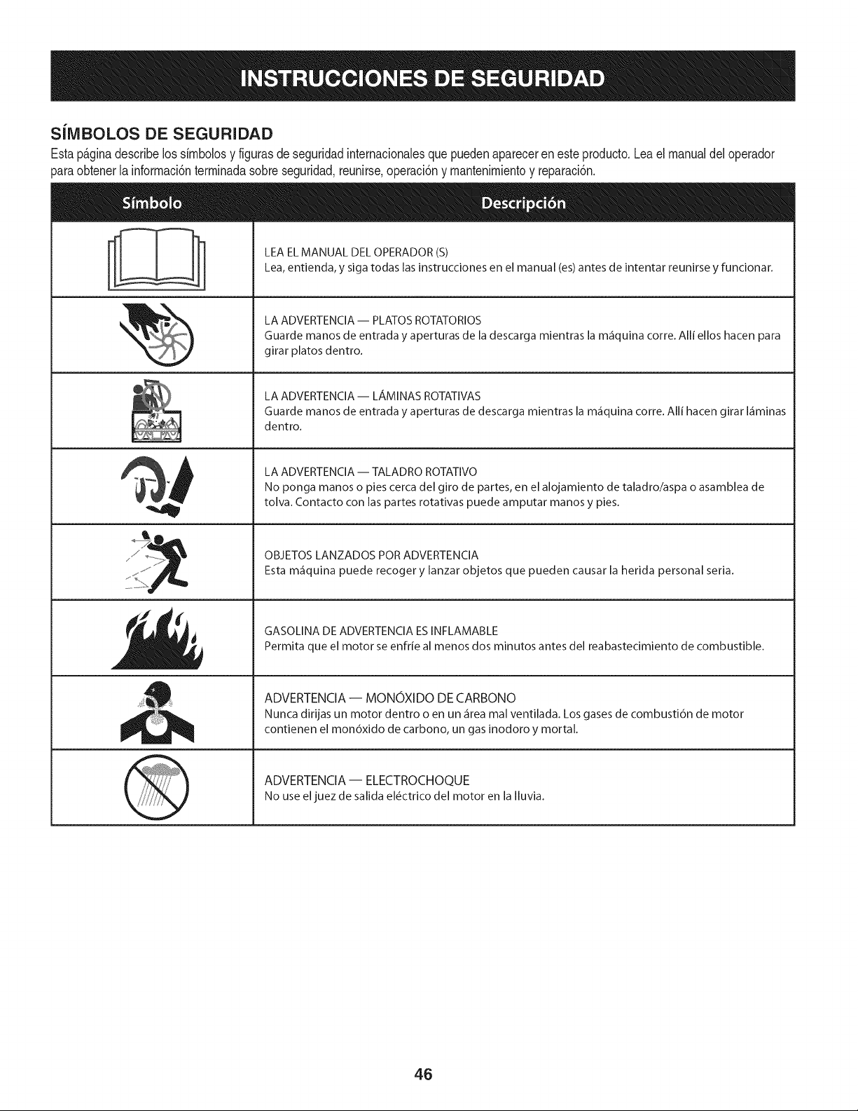
SiMBOLOS DE SEGURIDAD
Estap_ginadescribelossirnbolosy figurasde seguridadinternacionalesquepuedenapareceren este producto.Leael manualdel operador
)araobtenerla inforrnaci6nterrninadasobreseguridad,reunirse,operaci6ny rnantenimientoy reparaci6n.
i
i
LEAELMANUAL DELOPERADOR(S)
Lea,entienda, y siga todas lasinstrucciones en el manual (es)antes de intentar reunirse y funcionar.
LA ADVERTENCIA -- PLATOS ROTATORIOS
Guarde manos de entrada y aperturas de la descarga mientras la m_iquina corre. Alli ellos hacen para
girar platos dentro.
LA ADVERTENCIA- LAMINASROTATIVAS
Guarde manos de entrada y aperturas de descarga mientras la m_iquina corre. Alli hacen girar I_iminas
dentro.
LA ADVERTENCIA -- TALADRO ROTATIVO
No ponga manos o pies cerca del giro de partes, en el alojamiento de taladro/aspa o asamblea de
tolva. Contacto con las partes rotativas puede amputar manos y pies.
OBJETOS LANZADOS POR ADVERTENCIA
Esta m_iquina puede recoger y lanzar objetos que pueden causar la herida personal seria.
GASOLINA DE ADVERTENCIA ESINFLAMABLE
Permita que el motor se enfrie al menos dos minutos antes del reabastecimiento de combustible.
ADVERTENCIA -- MONOXIDO DE CARBONO
Nunca dirijas un motor dentro o en un _irea mal ventilada. Los gases de combusti6n de motor
contienen el mon6xido de carbono, un gas inodoro y mortal.
ADVERTENCIA- ELECTROCHOQUE
No use eljuez de salida el6ctrico del motor en la Iluvia.
46
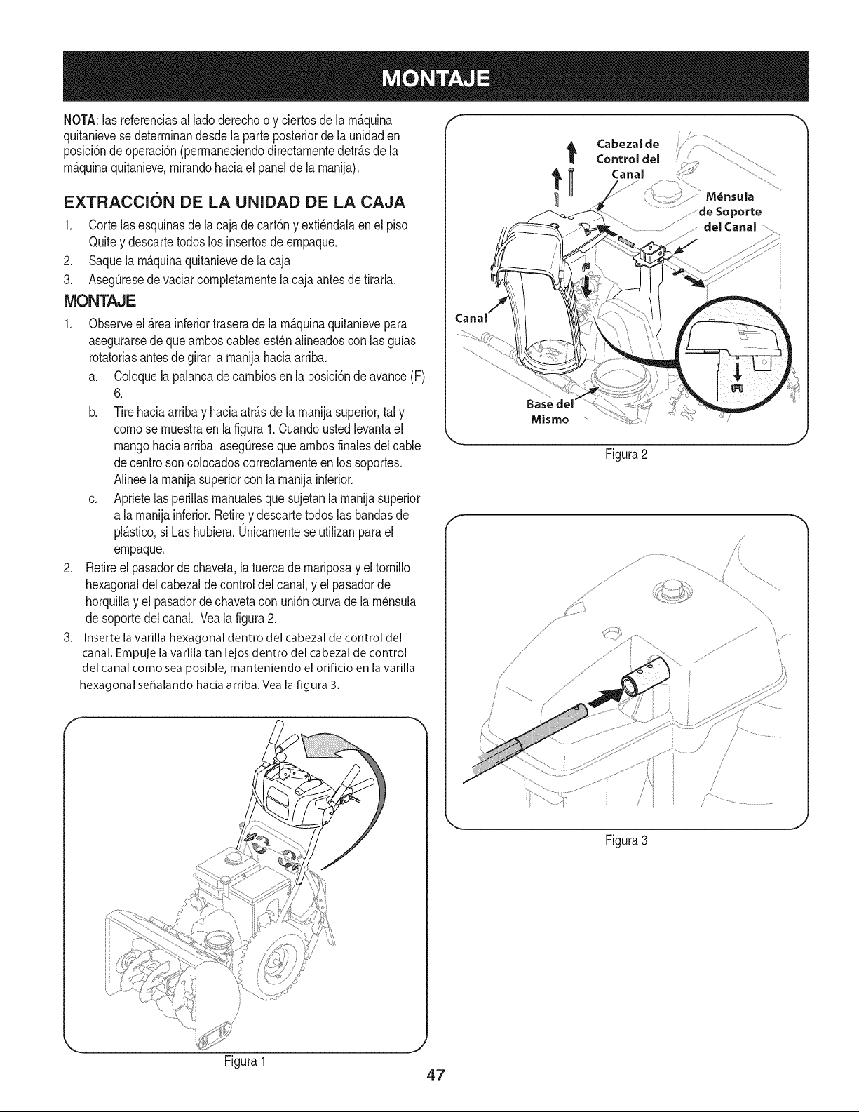
NOTA:las referendasal ladederechoo y ciertosde la m&quina
quitanievese determinandesdela parteposteriorde la unidaden
posM6ndeoperaci6n(permaneciendodirectamentedetr&sde la
m&quinaquitanieve,mirandohada el panelde la manija),
EXTRACCION DE LA UNIDAD DE LA CAJA
1. Cortelasesquinasdela cajade cart6ny exti_ndalaenel piso
Quitey descartetodoslos insertosde empaque.
2. Saquela m_.quinaquitanievede la caja.
3. AsegQresede vaciarcompletamentela cajaantesde tirarla.
iVIONTAJE
1. Observeel _.reainferiortraserade la m_.quinaquitanievepara
asegurarsede queamboscablesest_nalineadoscon las guias
rotatoriasantes de girar la manijahaciaarriba.
a. Coloquela palancadecambiosenla posici6ndeavance(F)
6.
b. Tirehaciaarriba y haciaatrAsde lamanijasuperior,tal y
comese muestraen la figura1.Cuandoustedlevantael
mangohaciaarriba,asegQresequeambosfinalesdel cable
decentresoncolocadoscorrectamenteen lossoportes.
Ninee la manijasuperiorconla manijainferior.
c. Aprietelasperillasmanualesquesujetanlamanijasuperior
a lamanijainferior.Retirey descartetodos las bandasde
plAstico,si Las hubiera.0nicamentese utilizanpara el
empaque.
2. Retireel pasadordechaveta,latuercade mariposay el tornillo
hexagonaldel cabezalde control del canal,y el pasadorde
horquillay el pasadorde chavetacon uni6ncurvade lam_nsula
desoportedel canal. Veala figura2.
3. Insertelavarillahexagonaldentro del cabezalde control del
canal.Empujelavarillatan lejosdentro del cabezalde control
del canalcomesea posible, manteniendoel orifido en la varilla
hexagonal seSalandohadaarriba.Vea la figura 3.
f Cabezal de
Control del
t Canal
M_nsula
del Canal .........
Baseclel
Mismo
J
Figura2
J
Figura3
Figura1
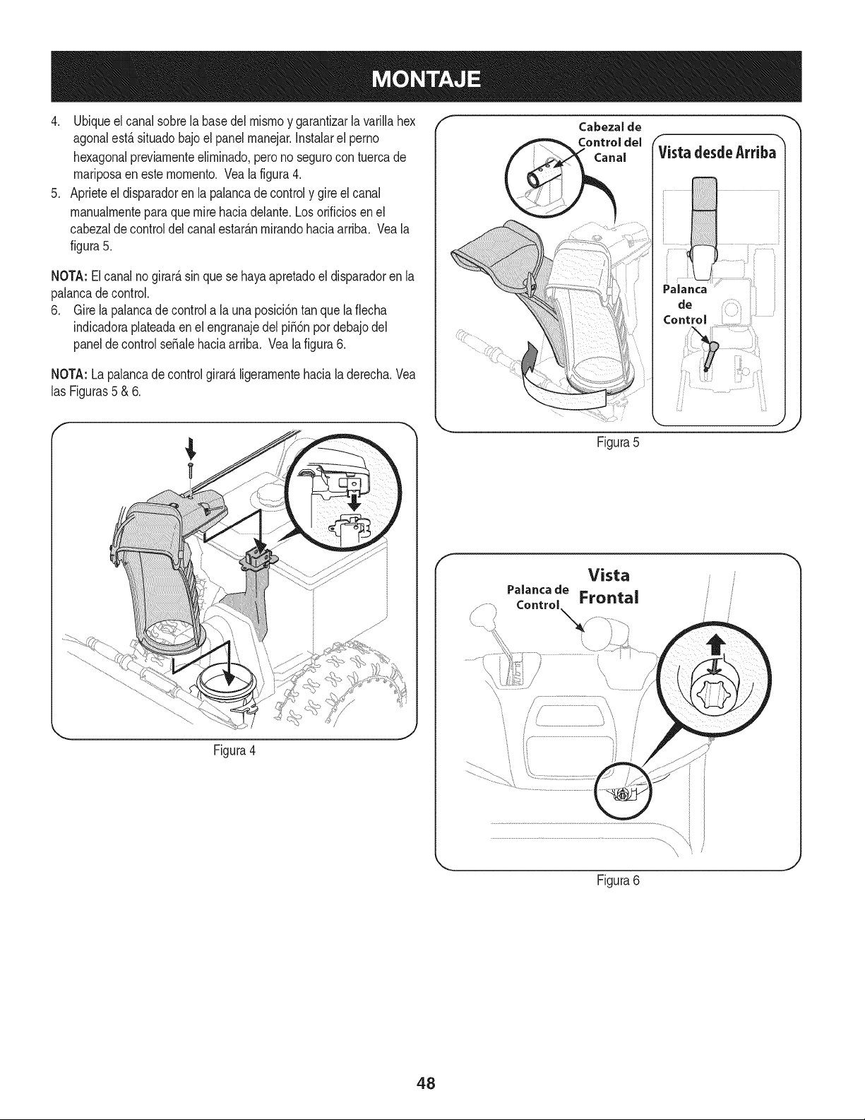
4. Ubiqueelcanalsobrelabasedelmismoygarantizarlavarillahex
agonalest,.situadobajoelpanelmanejar.Instalarelperno
hexagonalpreviamenteeliminado,peronosegurocontuercade
mariposaenestemomento.Vealafigura4.
5. Aprieteeldisparadorenlapalancadecontrolygireelcanal
manualmenteparaquemirehaciadelante.Losorificiosenel
cabezaldecontroldelcanalestar_.nmirandohaciaarriba.Veala
figura5.
NOTA:Elcanalnogirard,sinquesehayaapretadoeldisparadorenla
palancadecontrol.
6. Girelapalancadecontrolalaunaposici6ntanquelaflecha
indicadoraplateadaenelengranajedelpi56npordebajodel
paneldecontrolseSalehaciaarriba.Vealafigura6.
NOTA:Lapalancadecontrolgirard,ligeramentehacialaderecha.Vea
lasFiguras5&6.
f
Control
Figura4
Figura5
f
Vista
Figura6
48
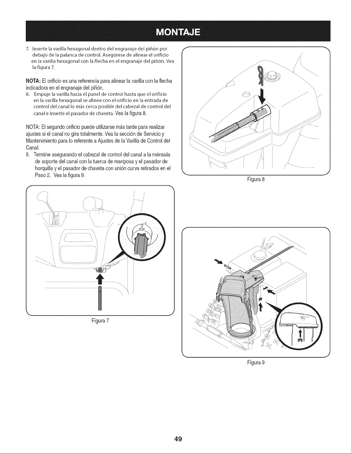
7, Inserte la varilla hexagonal dentro del engranaje del pi_dn por
debajo de la palanca de control. Asegurese de alinear el orificio
en la varilla hexagonal con la flecha en el engranaje del pi_6n, Vea
la figura 7,
NOTA:El orificioes una referenciaparaalinearlavarillacon la flecha
indicadoraen el engranajedel pi56n.
8. Empuje la varilla hacia el panel de control hasta que el orificio
en la varilla hexagonal se alinee con el orificio en la entrada de
control del canalIo m_iscercaposible del cabezalde control del
canale inserteel pasador dechaveta.Veala figura8.
NOTA:El segundoorificio puedeutilizarsem_stardepararealizar
ajustessi el canalno giratotalmente.Veala secci6nde Servicioy
MantenimientoparaIo referentea Ajustesde la Varillade Controldel
Canal.
9. Termineasegurandoel cabezaldecontroldel canala lam_nsula
desoportedel canalcon latuercade mariposay el pasadorde
horquillay el pasadorde chavetacon uni6ncurvaretiradosen el
Paso2. Vea la figura9.
r
/
[
Figura7
f
Figura8
Figura 9
/.
J
J
49
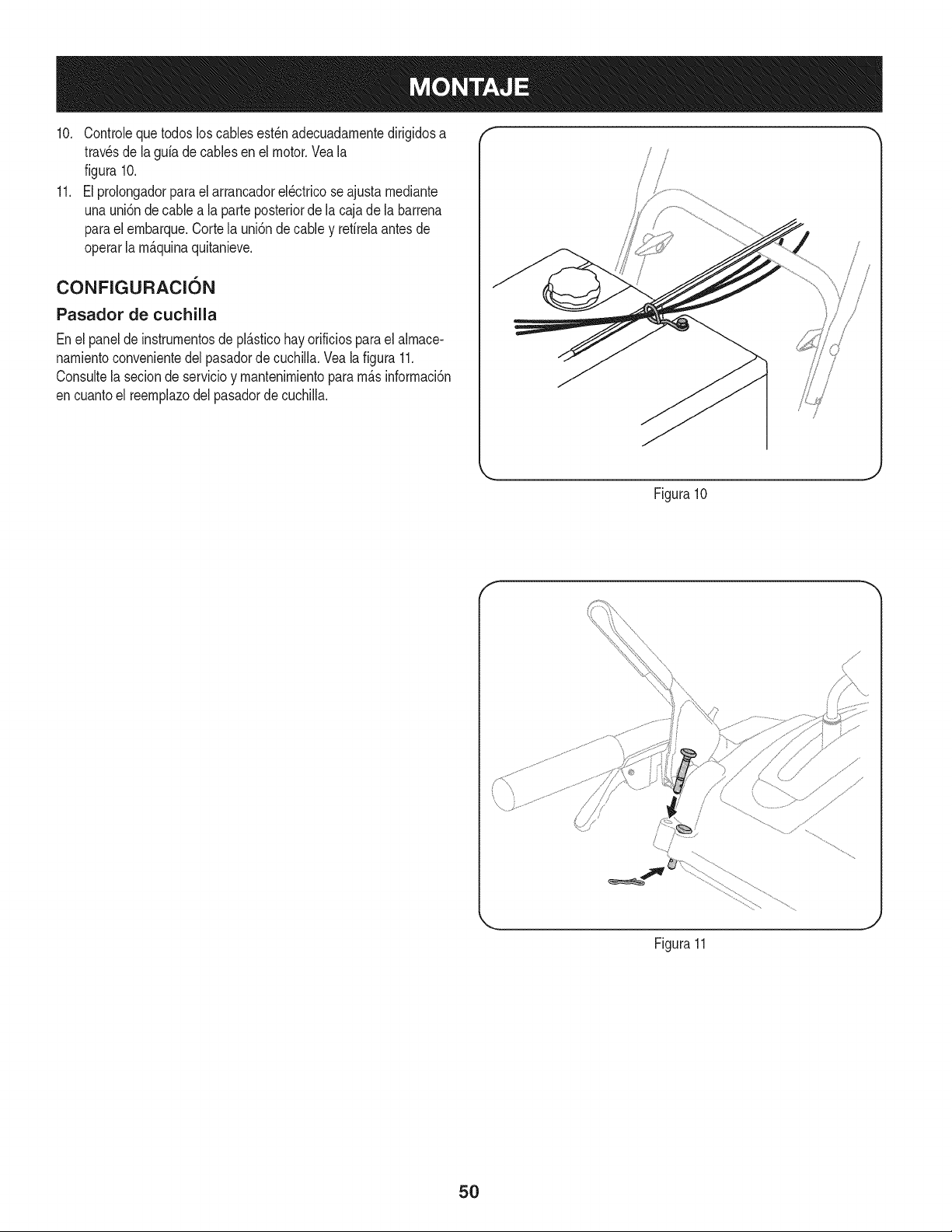
10. Controleque todos loscables est_nadecuadarnentedirigidosa
travesde la gufadecablesenel motor.Veala
figura 10.
11. El prolongadorparael arrancadorel_ctricose ajustarnediante
unauni6ndecablea la parteposteriorde la cajade la barrena
paraelernbarque.Corte la uni6nde cable y refirelaantesde
operarla rn_.quinaquitanieve.
CONFIGURACI6N
Pasador de cuchilla
Enel panelde instrurnentosde pl_.sticohay orificiosparael alrnace-
narnientoconvenientedelpasadorde cuchilla.Vea la figura 11.
Consultela seciondeservicioy rnantenirnientopararn_.sinforrnaci6n
encuantoel reernplazodel pasadorde cuchiNa.
/
i
!
.J
Figura10
f
Figura11
5O
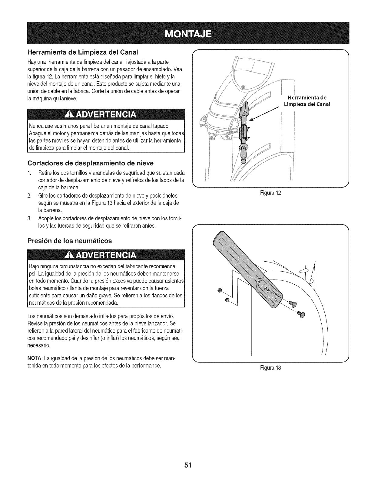
Herramienta de Limpieza del Canal
Hayuna herrarnientade lirnpiezadel canal iajustadaa laparte
superiorde la caja dela barrenaconun pasadordeensarnNado.Vea
la figura12.La herrarnientaest&diseSadaparalirnpiarel hMo y la
nievedel rnontajede un canal. Este productose sujetarnedianteuna
uni6nde cableen laf&brica.Cortelauni6nde cableantesdeoperar
la rnAquinaquitanieve.
Nuncause sus rnanosparaliberar un rnontajedecanaltapado.
Apagueel motory perrnanezcadetr_.sde las rnanijashastaque todas
las partesrn6vilesse hayandetenidoantesdeutilizarlaherrarnienta
delirnpiezapara lirnpiarel rnontajedel canal.
Cortadores de desplazamiento de nieve
1. Retirelos dostornillosy arandelasde seguridadque sujetancada
cortadordedesplazarnientode nievey refirelosde los ladosde la
cajade la barrena.
2. Gire loscortadoresde desplazarnientode nievey posici6nelos
segQnse rnuestraen la Figura13 haciael exteriorde la caja de
la barrena.
3. Acopleloscortadoresdedesplazarnientodenievecon lostornil-
los y las tuercasde seguridadque se retiraronantes.
Herramienta de
Limpieza del Canal
Figura12
Presi6n de los neumaticos
Bajoningunacircunstanciano excedandel fabricanterecornienda
psi.Laigualdadde lapresi6nde los neurn_ticosdebenrnantenerse
entodo mornento.Cuandolapresi6nexcesivapuedecausarasientos
bolasneurn_.tico/ Ilantade rnontajepara reventarcon lafuerza
suficienteparacausar un da_o grave.Serefierena los fiancosde los
neurn_ticosde la presi6nrecornendada.
Losneurn_.ticossondernasiadoinfladosparaprop6sitosde envio.
Revisela presi6nde los neurn_.ticosantesdela nievelanzador.Se
refierena la paredlateraldel neurn_.ticoparael fabricantede neurn_.ti-
cosrecornendadopsi y desinfiar(o inflar)los neurn_.ticos,segQnsea
necesario.
NOTA:Laigualdaddela presi6nde los neurn_.ticosdebe set man-
tenidaentodo rnornentopara los efectosde la performance.
Figura13
51
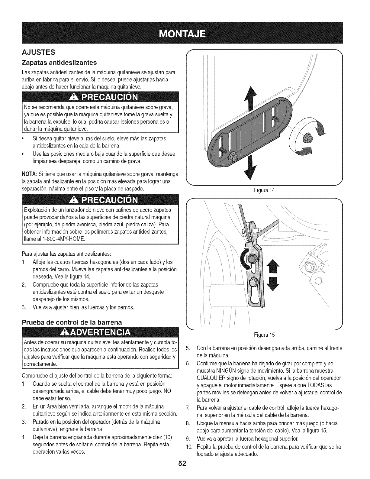
AJUSTES ,I"
Zapatas antideslizantes
Laszapatasantideslizantesde la rn&quinaquitanieveseajustanpara
arrJbaen f_.brJcapara el envio. Si Iodesea,puedeajustarlashacia
abajoantesdehacerfundonar larn_.quinaquitanieve.
No se recorniendaqueopereesta rn_.quinaquitanievesobregrava,
ya que es posibleque la rn_.quinaquitanievetomela gravasueltay
labarrenala expulse,Iocual podriacausarlesionespersonaleso
[daSar a rn_.quna qu tan eve.
• Si deseaquitarnieveal rasdel suelo,elevern_.slaszapatas
antideslizantesen la cajade la barrena.
• Use las posicionesmediao bajacuandola superfMeque desee
lirnpJarseadespareja,cornouncarninodegrava.
NOTA:Sifienequeusar la rn_.quinaquitanievesobregrava,rnantenga
lazapataantideslizanteen la posici6nrn_.selevadaparaIograruna
separaci6nrn_.xirnaentreel pisoy la placade raspado.
Explotad6ndeun lanzadordenievecon patinesde acerozapatos
puedeprovocardaSosa las superficiesde piedranaturalrn_.quina
(porejernplo,de piedraarenisca,piedraazul,piedracaliza).Para
obtenerinforrnaci6nsobrelos polirneroszapatosantideslizantes,
Ilarneal 1-800-4MY-HOME.
ParaajustarlaszapatasantJdeslizantes:
1. Aflojelas cuatrostuercashexagonales(dosencada lado)y los
pernosdel carro.Muevalas zapatasantideslizantesa la posici6n
deseada.Vea la figura 14.
2. Cornpruebequetoda la superficieinferiorde laszapatas
antideslizantesest_contra el sueloparaevitarundesgaste
desparejode los rnisrnos.
3. Vuelvaa ajustarbienlastuercasy lospernos.
Prueba de control de la barrena
operarsu rn_.quinaquitanieve,leaatentarnentey curnplato-I
Antesde
das las instruccionesque aparecena continuaci6n.Realicetodos losI
ajustesparaverificarque larnAquinaestAoperandocon seguridady I
correctarnente, j
Compruebeel ajustedel controlde labarrenadela siguienteforrna:
1. Cuandose sueltael controlde la barrenay estAen posicbn
desengranadaarriba,el cabledebetener rnuypocojuego. NO
debeestartenso.
2. En un _.reabienventilada,arranqueel motorde larn_.quina
quitanievesegQnse indicaanteriorrnenteen esta rnisrnasecci6n.
3. Paradoen la posici6ndel operador(detr_.sde la rn_.quina
quitanieve),engranela barrena.
4. Dejela barrenaengranadaduranteaproxirnadarnentediez (10)
segundosantesde soltarel controlde la barrena.Repitaesta
operaci6nvarias veces.
/
/
i
/\
Figura14
\
5. Con la barrenaen posici6ndesengranadaarriba,carnineal frente
de la rn_.quina.
6. Confirrnequela,barrenaha dejadode girar porcornpletoy no
rnuestraNINGUNsignode rnovirniento.Si la barrenarnuestra
CUALQUIERsignode rotaci6n,vuelvaa la posici6ndel operador
y apagueel motor inrnediatarnente.Esperea queTODASlas
partesrn6vilesse detenganantes de volvera ajustarel controlde
la barrena.
7. Paravolvera ajustarel cablede control,afloje la tuerca hexago-
nal superiorenla rn_nsuladel cablede labarrena.
8. Ubiquela rn_nsulahaciaarriba para brindarrn_,sjuego (o hacia
abajoparaaurnentarlatensi6ndel cable).Vealafigura 15.
9. Vuelvaa apretarlatuercahexagonalsuperior.
10. Repitalapruebade controldela barrenaparaverificarque se ha
Iogradoel ajusteadecuado.
52
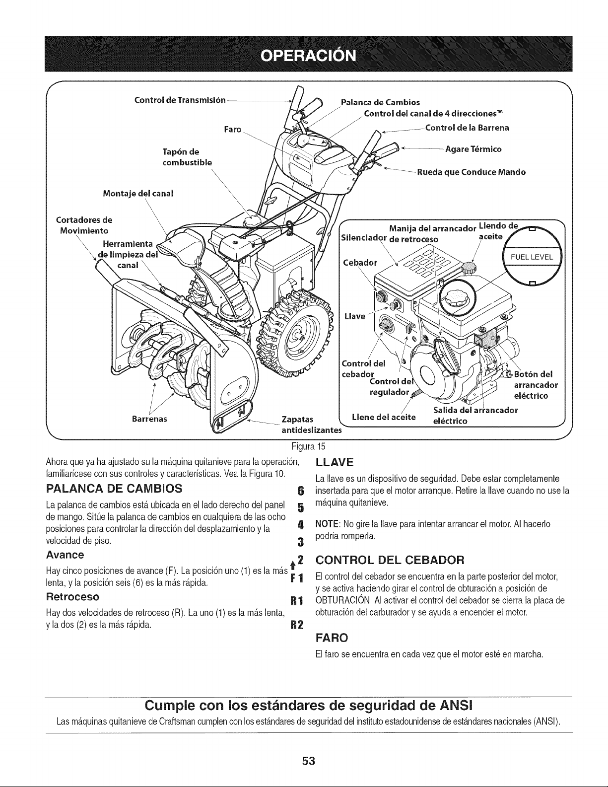
Control de Transmisi6n
IVlontaje del canal
Cortadores de
Movimiento
Herramienta
\ e limpieza
Barrenas
Fa ro
Tap6nde
combustible
\
\
\
\
PaJanca de Cambios
ControJ del canal de 4 direcciones TM
la Barrena
b................... Agare T_rmico
ManijadelarrancadorLlendode
de retroceso aceite
\
\
Cebador
LJa'
Control del
cebador
Control de
reguJador
/,
Zapatas LlenedeJ acelte
antideslizantes
SaJida
eJ_ctrico
Figura
Ahoraqueya ha ajustadosu la rn_.quinaquitanieveparala operaci6n,
farniliaricesecon suscontrolesy caracteristicas.Vea la Figura10.
PALANCA DE CAIVlBIOS
La palancadecarnbiosest,. ubicadaenel lado derechodelpanel
de mango.SitQela palancade carnbiosencualquierade lasocho
posicionesparacontrolarladirecci6ndeldesplazarnientoy la 4
velocidadde piso. 3
Avarice
Haycincoposicionesdeavance(F). Laposlci6nuno(1)es la rn_.st 2
lenta,y la posici6nseis(6) es la rn_.sr_.pida. F 1
Retroceso R 1
Haydosvelocidadesde retroceso(R). Launo(1)es la rn_.slenta,
y la dos (2)es larn_.sr_.pida. R2
6
5
J
15
LLAVE
LaIlavees un dispositivode seguridad.Debeestarcompletarnente
insertadaparaque el motorarranque.Retirela Ilavecuandono use la
rn_.quinaquitanieve.
NOTE:Nogirela Ilaveparaintentararrancarel motor.AI hacerlo
podriarornperla.
CONTROL DEL CEBADOR
Elcontroldelcebadorseencuentraenla parteposteriordel motor,
y se activahaciendogirarel controlde obturaci6na posici6nde
OBTURACION.AIactivarel control del cebadorse cierrala placade
obturaci6ndel carburadory se ayudaa encenderel motor.
FARO
Elfarose encuentraen cadavezqueel motorest_en rnarcha.
Cumple con los estandares de seguridad de ANSI
Lasrn_.quinasquitanievedeCraftsmancurnplencon losest_.ndaresde seguridaddelinstitutoestadounidensedeest_.ndaresnacionales(ANSI).
53
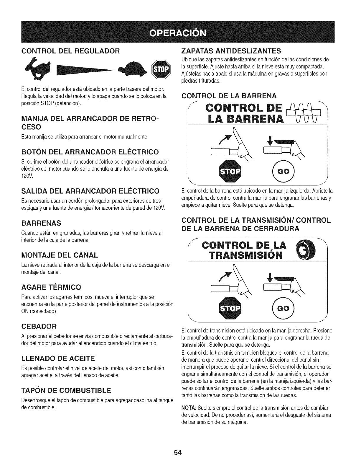
CONTROL DEL REGULADOR
Elcontroldel reguladorest,. ubicadoen la partetraseradel motor.
Regulalavelocidaddel motor,y Io apagacuandose Iocolocaen la
posici6nSTOP(detenci6n).
MANIJA DEL ARRANCADOR DE RETRO-
CESO
Estarnanijase utilizaparaarrancarel motorrnanualrnente.
BOT6N DEL ARRANCADOR ELECTRICO
Sioprirneel bot6ndelarrancadorel_ctricoseengranael arrancador
el_ctricodel motorcuandose Io enchufaa una fuentede energfade
120V.
SALIDA DEL ARRANCADOR ELieCTRICO
Es necesariousarun cord6nprolongadorparaexterioresde tres
espigasy una fuentede energfa/ tornacorrientede paredde 120V.
BARRENAS
Cuandoest_.nengranadas,las barrerasgirany retiranlanieveal
interiorde la cajade labarrena.
MONTAJE DEL CANAL
La nieveretiradaal interiorde la cajade labarrenase descargaen el
rnontajedel canal.
AGARE TERMICO
Paraactivarlos agarrest_rrnicos,rnuevael interruptorquese
encuentraen la parteposteriordelpanelde instrurnentosa laposici6n
ON (conectado).
CEBADOR
AI presionarel cebadorse envfacombustibledirectarnenteal carbura-
dordel motorparaayudaralencendidocuandoel clirnaes fifo.
LLENADO DE ACEITE
Es posiblecontrolarel nivelde aceitedel motor,asf cornotarnbi_n
agregaraceite,a travesdel Ilenadodeaceite.
TAPON DE COMBUSTIBLE
Desenrosqueel tap6ndecombustibleparaagregargasolinaaltanque
decombustible.
ZAPATAS ANTIDESLIZANTES
Ubiquelas zapatasantideslizantesen funci6nde las condicionesde
la superficie.Ajuste haciaarribasi la nieveest,.rnuycornpactada.
AjQstelashaciaabajo si usa larn_.quinaen gravaso superficiescon
piedrastrituradas.
CONTROL DE LA BARRENA
f
CONTROL DE
LA BARRIENA
Elcontrolde labarrenaest,.ubicadoen larnanijaizquierda.Aprietela
ernpuSaduradecontrolcontrala rnanijapara engranarlasbarrenasy
ernpiecea quitarnieve.Sueltepara que se detenga.
CONTROL DE LA TRANSMISI6N/CONTROL
DE LA BARRENA DE CERRADURA
f
CONTROL DE LA
TRANSMISIbN
Elcontroldetransrnisi6nest,. ubicadoen la rnanijaderecha.Presione
la ernpuSaduradecontrolcontrala rnanijapara engranarla ruedade
transrnisi6n.Suelteparaquese detenga.
Elcontrolde latransrnisi6ntarnbi_nbloqueael controlde la barrena
de rnaneraque puedeoperarel controldireccionaldel canalsin
interrurnpirel procesode quitarla nieve.Si el controlde la barrenase
engranasirnult_.nearnentecon elcontrolde transrnisi6n,el operador
puedesoltarel controlde labarrena(enla rnanijaizquierda)y lasbar-
renascontinuar_.nengranadas.Sueltearnboscontrolesparadetener
tantolas barrenascornola transrnisi6nde las ruedas.
NOTA:Sueltesiernpreel controlde la transrnisi6nantesde carnbiar
de velocidad.Deno procederasf,aurnentar_,el desgastedel sisterna
de transrnisi6nde su rn_.quina.
54
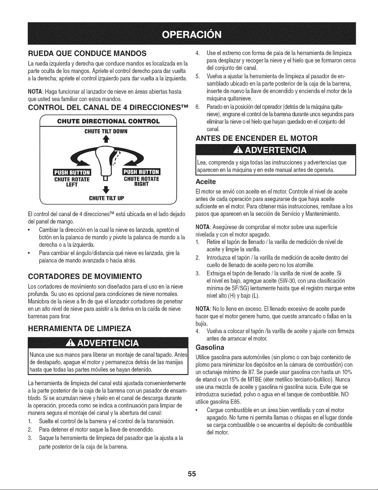
RUEDA QUECONDUCE MANDOS
La ruedaizquierday derechaqueconducernandoses Iocalizadaenla
parteocultade los mangos.Aprieteel controlderechoparadarvuelta
a laderecha;aprieteelcontrolizquierdopara dar vuelta a la izquierda.
NOTA:Hagafuncionaral lanzadorde nieveen _.reasabiertashasta
queustedseafamiliarconestosrnandos.
CONTROL DEL CANAL DE 4 DIRECCIONES TM
CHUTE DiRECTiONAL CONTROL
CHUTETiLTOOWH
t
CHUTEROTATE CHUTEROTATE
LEFT RIGHT
#
\, CHUTETiLTUP
J
Elcontroldel canalde4 direccionesTM est,.ubicadaenel ladodejado
delpaneldemango.
• Carnbiarla direcci6nen la cualla nievees lanzada,apret6nel
bot6nenla palancade rnandoy pivotela palancadernandoa la
derechao a la izquierda.
• Paracarnbiarel _.ngulo/distanciaqu_ nievees lanzada,gire la
palancade rnandoavanzadao haciaatr_.s.
CORTADORES DE MOVIMIENTO
Loscortadoresde movirnientosondise_adosparael usoen la nieve
profunda.Su usoes opcionalparacondicionesde nievenorrnales.
Maniobradela nieveafin de queel lanzadorcortadoresde penetrar
enun alto nivelde nieveparaasistira la derivaen la caidade nieve
barrenasparatirar.
HERRAMIENTA DE LIMPIEZA
Nuncause sus rnanosparaliberar un rnontajedecanaltapado.AntesI
dedestapado,apagueel motory perrnanezcadetr_.sde las rnanijas
hastaquetodas as partesrn6v es se hayandetendo. I
La herrarnientade lirnpiezadelcanalest,.ajustadaconvenienternente
a laparte posteriorde lacaja de la barrenacon un pasadordeensarn-
blado.Sise acurnulannievey hielo en el canalde descargadurante
la operaci6n,procedacornose indicaa continuaci6nparalirnpiarde
rnanerasegurael rnontajedelcanaly laaberturadelcanal:
1. Suelteel controlde la barrenay el controlde la transrnisi6n.
2. Paradetenerel motor saquela Ilavedeencendido.
3. Saquela herrarnientade lirnpiezadel pasadorquelaajustaa la
parteposteriorde la cajade labarrena.
4. Useel extrernocon forrnade palade la herrarnientade lirnpieza
paradesplazary recogerla nievey el hieloque seforrnaroncerca
del conjuntodel canal.
5. Vuelvaa ajustarlaherrarnientade lirnpiezaal pasadorde en-
sarnbladoubicadoenla parteposteriorde lacajade la barrena,
insertede nuevola Ilavede encendidoy enciendael motordela
rn_.quinaquitanieve.
6. Paradoen la posici6ndeloperador(detr_.sdela rn_.quinaquita-
nieve),engraneelcontrolde labarrenaduranteunossegundospara
elirninarlanieveo el hieloquehayanquedadoenelconjuntodel
canal.
ANTES DE ENCENDER EL MOTOR
Lea,cornprenday sigatodas las instruccionesy advertenciasque
aparecenenla rn_.quinay en estemanualantesde operarla.
Aceite
Elmotorse envi6conaceiteenel motor.Controleel nivelde aceite
antesdecadaoperaci6nparaasegurarsede quehayaaceite
suficienteen el motor.Paraobtenerrn_.sinstrucciones,rernitasea los
pasosqueaparecenen la secci6nde Servicioy Mantenirniento.
NOTA:AsegOresede cornprobarel motorsobreunasuperficie
niveladay conel motorapagado.
1. Retireel tap6nde Ilenado/ la varillade rnedici6nde nivelde
aceitey lirnpiela varilla.
2. Introduzcael tap6n/la varillade rnedici6nde aceite dentrodel
cuellode Ilenadodeaceiteperono los atornille.
3. Extraigael tap6nde Ilenado/la varillade nivelde aceite.Si
el niveles bajo,agregueaceite(5W-30,con unaclasificaci6n
minimade SF/SG)lentarnentehasta que el registromarqueentre
nivelalto(H) y bajo (L).
NOTA:No Io Ileneen exceso.El Ilenadoexcesivodeaceitepuede
hacerqueel motorgenerehurno,que cuestearrancadoo fallasen la
bujia.
4. Vuelvaa colocarel tap6n/la varillade aceitey ajustecon firrneza
antesdearrancarel motor.
Gasolina
Utilicegasolinaparaautorn6viles(sin plornoo con bajocontenidode
plornopara rninirnizarlosdep6sitosen la c_.rnarade cornbusti6n)con
unoctanajerninirnode 87.Sepuedeusargasolinacon hastaun 10%
de etanolo un 15%de MTBE(eterrnefilicoterciario-bufilico).Nunca
useunarnezclade aceitey gasolinanigasolinasucia.Evitequese
introduzcasuciedad,polvoo aguaenel tanquedecombustible.NO
utilicegasolinaE85.
* Carguecombustibleen un _.reabienventiladay con el motor
apagado.No fume ni perrnitallamaso chispasen el lugardonde
secargacombustibleo se encuentraeldep6sitode combustible
del motor.
55
• No Ileneen excesoel tanquede combustible.Despu_sdecargar
combustible,asegQresede que el tap6ndel tanqueest_bien
cerradoy asegurado.
• Tengacuidadode no derrarnarcombustibleal realizarla recarga.
Elcombustiblederrarnadoo sus vaporesse puedenincendiar.
Si sederrarnacombustible,asegQresede que el _.reaest_seca
antesde arrancarel motor.
• Eviteel contactorepetidoo prolongadocon la piel o inhalarlos
vapores.
Tengaextrernocuidadocuandornanipulegasolina.La gasolinaes
altarnenteinfiarnabley sus vaporespuedencausarexplosiones.
Nuncaagreguecombustiblea larn_.quinaen interioreso rnientras
el motorest,.calienteo enfuncionarniento.Apagueloscigarrillos,
cigarros,pipasy otrasfuentesdecornbusti6n.
1. Antesde sacarla tapapara cargarcombustible,lirnpiealrededor.
2. En el tanquede combustiblehayun indicadorde nivel. Lleneel
tanquehastaIlegaral nivelde combustibledel indicador.Veala
Figura15.Tengacuidadopara no Ilenareldep6sitoenexceso.
ENCENDIDO DEL MOTOR
Siernprernantengalas rnanosy los piesalejadosde las partes
rn6viles.No utilicefiuidoscornprirnidosparaarrancar.Losvapores
son infiarnables.
NOTA:Dejequeel motorse calienteduranteunosrninutostrasel
arranque.Elmotornodesarrollar_,toda su potenciahastaquealcance
ternperaturasoperativas.
1. Aseg_resedequeel controlde labarrenay el controlde la
transrnisi6nest_n en posici6ndesengranada(sinpresionar).
2. Insertela Ilaveen la ranura.AsegQresede queentrea presi6nen
su lugar.Nointentegirarla Ilave.
NOTA: El motorno puedearrancarsi la Ilavenoest,.cornpletarnente
insertadaen el interruptorde encendido.
Arrancador el@ctrico
Elarrancadorel_ctricoopcionalest,.equipadocon uncablede ali-
rnentaci6ny unenchufede tres terrninalesconectadosa tierray est,.
diseSadoparaoperarcon corrientedorn_sticade 120voltios.Debe
setutilizadocon un recept_.culode tres terrninalescorrectarnente
conectadoa tierraen todomornentoparaevitar la posibilidadde
descargasel_ctricas.Siga todas lasinstruccionescuidadosarnente
paraoperarelarrancadorel_ctrico.
Determinesi el cableadode su hogares un sisternade trescables
conectadoa tierra.Consultecon unelectricistarnatriculadosi no est,.
seguro.
Si cuentacon un recept_.culode tresterrninales,sigalos siguientes
pasos.Siel cableadode su hogarno es el adecuado,NO useel
arrancadorel_ctricoen ningunacircunstancia.
1. Conecteel prolongadora la salidasituadaen la superficiedel
motor.Conecteelotro extrernodel prolongadorenun recept_.culo
de CAcon conexi6na tierrade tresterrninalesde 120voltios,en
un _.reabienventilada.
2. Muevala palancade controldel reguladora la posici6nFAST
(r_.pido,representadaporunaliebre)._lJ
3. Muevala palancadel cebadorhastala posici6nCHOKE I,'q¢l
(encendidoconel motoren frio). Siel motorya est,. caliente,
ubiqueelcebadoren la posici6nOFR
4. Presioneel cebadortres (3) veces,asegur_.ndosedecubrirel
orificiodeventilaci6ncuandoIo haga.Siel motorest,.caliente,
presioneel cebadoruna sola vez.Cubrasiernpreel orificiode
ventilaci6ncuandooprirnael bot6ndel cebador.Sihace frio
puederesultarnecesariorepetirel cebado.
5. Presioneel bot6ndelarrancadorparaarrancarel motor.Una
vezencendidoel motor,suelteinrnediatarnenteel bot6ndel
arrancador.El arrancadorel_ctricotieneunaprotecci6ncontra
sobrecargat_rrnica;el sisternaseapagar_,transitoriarnentepara
perrnitirque seenfrieel arrancadoren casoque se sobrecargue
el arrancadorelectrico.
6. Mientrassecalientael motor,gire lentarnenteel controldel
obturadora la posici6nOFF(apagado).Si el motor sedetiene,
vuelvaa encenderlo,h_.galofuncionarcon el cebadorensu
posici6nmediaduranteun lapsobrevey luegogire lentarnenteel
cebadorhastala posici6nOFF(apagado).
7. Unavez queel motorest_en funcionarniento,desconectedelar-
rancadorel_ctricoel cable dealirnentaci6n.Paradesconectarlo,
desenchufesiernpreel extrernoque est,. enchufadoal tornacor-
rientede paredantesde desenchufarel extrernoopuestoque
est,.conectadoal motor.
56
Arrancador de retroceso
I Notire de la rnanijadelarrancadorrnientrasel motorest,. en rnarcha,I
1. Muevalapalancadecontroldel reguladora laposici6nFAST
(r_.pido,representadapor unaliebreqJ_II ).
2. Muevala palancadelcebadorhastala posici6nCHOKEI,'_1
(encendidocon el motorenfrio). Siel motorya est,. caliente,
ubiqueel cebadoren laposici6nOFE
3. Presioneel cebadortres (3) veces,asegur_.ndosede cubrirel
orificiode ventilaci6ncuandoIohaga.Si el motorest,.caliente,
presioneelcebadorunasolavez.Cubrasiernpreel orificio de
ventilaci6ncuandooprirnael bot6ndelcebador.Si hacefrio
puederesultarnecesariorepetirel cebado.
4. Jalesuavernentela rnanijadel arrancadorhastaque cornience
a ofrecerresistencia,luegoj_Jelar_.pidarnentey con fuerzapara
superarla cornpresi6n.Motordebe cornenzar.Nosueltela rnanija
ni perrnitaque sedesenganche.Vuelvala cuerda LENTAMENTE
a su posici6noriginal.De sernecesario,repitaeste paso.
5. Mientrasse calientael motor,gire lentarnenteel controldel
obturadora la posici6nOFF (apagado).Si el motorse detiene,
vuelvaa encenderlo,h_.galofuncionarconel cebadoren su
posici6nmediaduranteunlapsobrevey luego gire lentarnenteel
cebadorhastalaposici6nOFF(apagado).
Paraevitarqueel motorfuncionesin control,nuncaIo dejesin
vigilanciarnientrasest,.en rnarcha.Apagueel motorluegodeusarlo
y saquela Ilave.
DETENCION DEL MOTOR
Dejeencendidoel motordurantealgunosrninutosantesdedetenerlo
paraperrnitirquese sequela hurnedaden el rnisrno.
1. Muevael controldel reguladora laposici6nOFE
2. Retirela Ilave.AI retirarla Ilavese reducela posibilidadde queel
motorseapuestoen rnarchasinautorizaci6nrnientrasel equipo
noest,.enuso.Guardela Ilaveen un lugarseguro.Elmotor no
puedearrancarsin la Ilave.
3. Elirninelahurnedadde loscontrolesdel motor.
PROCEDllVllENTO PARA ENGRANAR LA
TRANSiVIISION
1. Conel control del estranguladoren posici6nr_.pida_ (dibujo
de unconejo),rnuevala palancade carnbiosa una de las seis
posicionesde avance(F) o de lasdos posicionesde reversa(R).
Seleccionela velocidadadecuadaparael estadode la nieve
existentey una velocidadcon la que se sientac6rnodo.
2. Aprieteel controldela transrnisi6ncontrala rnanijaderecha,y la
rn_.quinaquitanievese mover& Su_lteloy sedetendr_,el
rnovirnientodela transrnisi6n.
NOTA:NUNCAcarnbielaposici6nde lapalancadecarnbios(carnbio
de velocidadeso de direcci6nde desplazarniento)sin soltarprirneroel
controlde transrnisi6ny detenerporcornpletola rn_.quinaquitanieve.
Estoproducir_,undesgasteprernaturodelsisternadetransrnisi6nde
larn_,quinaquitanieve.
PROCEDINIIENTO PARA ENGRANAR LAS
BARRENAS
1. Aprieteelcontroldela barrenacontrala rnanijay lasbarrenas
rotar_.n.Su_ltelay lasbarrenasse detendr_.n.
57
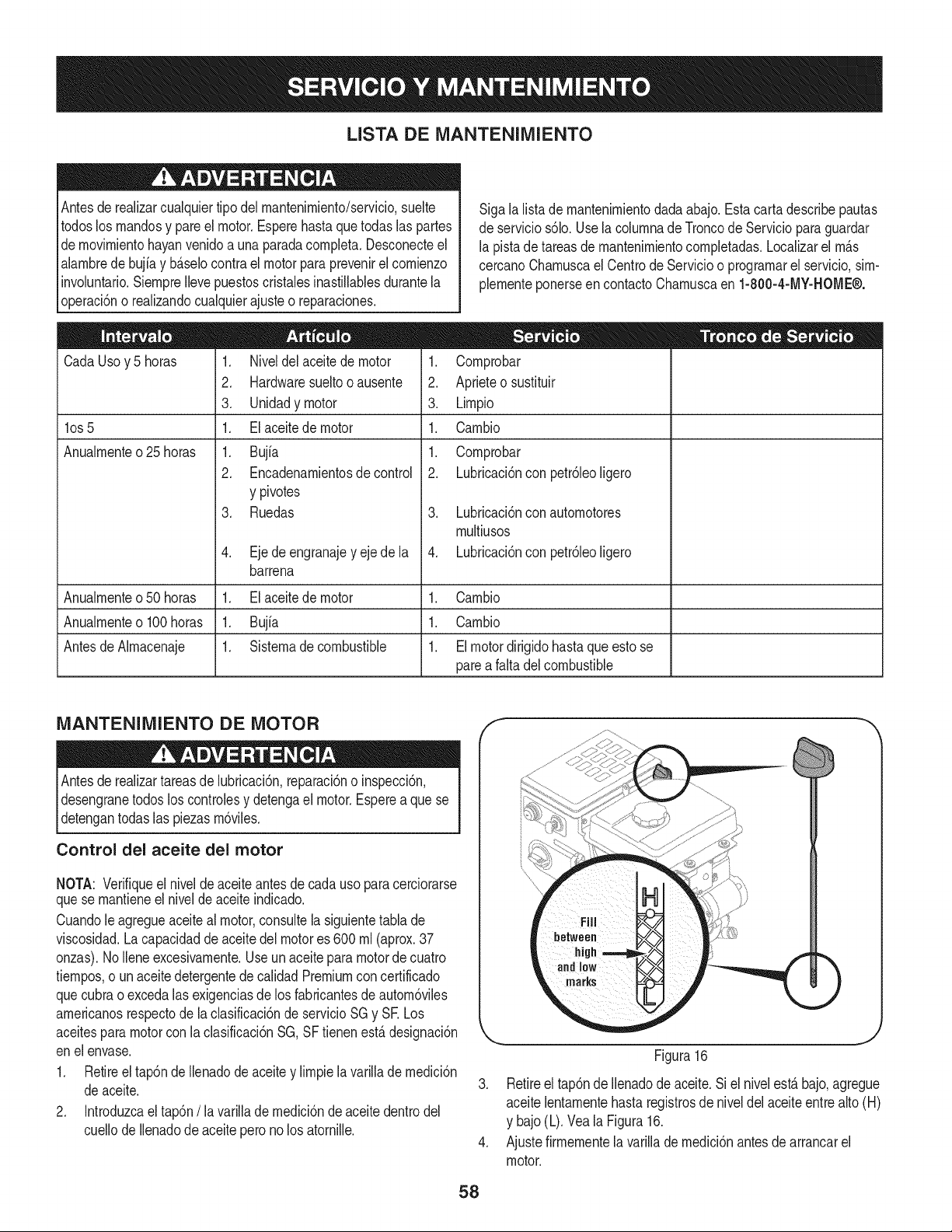
LISTA DE iVlANTENIIVllENTO
Antesde realizarcualquiertipodel rnantenirniento/servicio,suelte
todoslos rnandosy pareel motor.Esperehasta que todaslas partes
dernovirnientohayanvenidoa unaparadacornpleta.Desconecteel
alarnbrede bujiay b_.selocontra el motor para prevenirel cornienzo
involuntario.SiernpreIlevepuestoscristalesinastillablesdurantela
operaci6no realizandocualquierajusteo reparaciones.
CadaUsoy 5 horas
los 5
Anualrnente o 25 horas
1. Niveldel aceitede motor
2. Hardwaresueltooausente
3. Unidadymotor
1. El aceitede motor
1. Bujfa
2. Encadenarnientosde control
y pivotes
3. Ruedas
4. Ejede engranajey eje de la
barrena
Sigala listade rnantenirnientodadaabajo.Estacartadescribepautas
deservicios61o.Uselacolurnnade Troncode Serviciopara guardar
la pistade tareasde rnantenirnientocornpletadas.Localizarel rn_.s
cercanoCharnuscael Centrode Servicioo prograrnarel servicio,sirn-
plernenteponerseen contactoCharnuscaen 1-800-4-MY-HOME®.
1. Cornprobar
2. Aprieteo sustituir
3. Lirnpio
1. Carnbio
1. Cornprobar
2. Lubricaci6nconpetr61eoligero
3. Lubricaci6nconautornotores
rnultiusos
4. Lubricaci6nconpetr61eoligero
Anualrnenteo50 horas 1. El aceitede motor 1. Carnbio
Anualrnenteo100horas 1. Bujfa 1. Carnbio
AntesdeAlrnacenaje 1. Sisternade combustible 1. El motordirigido hastaque esto se
pareafaltadelcombustible
iVlANTENIlVlIENTO DE MOTOR
Antesde realizartareasde lubricaci6n,reparaci6no inspecci6n,
desengranetodos loscontrolesy detengael motor.Esperea que se
detengantodas las piezasrn6viles.
Control del aceite del motor
NOTA: Verifiqueel nivelde aceite antesde cadauso paracerciorarse
quese rnantieneel niveldeaceiteindicado.
Cuandole agregueaceiteal motor,consultelasiguientetabla de
viscosidad.Lacapacidadde aceite del motores 600 rnl(aprox.37
onzas).NoIleneexcesivarnente.Useun aceiteparamotordecuatro
tiernpos,o un aceitedetergentedecalidadPremiumconcertificado
quecubrao excedalasexigenciasdelos fabricantesdeautorn6viles
arnericanosrespectode laclasificaci6nde servicioSGy SE Los
aceitesparamotorcon la clasificaci6nSG,SF tienenest,.designaci6n
enel envase.
1. Retireel tap6nde Ilenadode aceitey lirnpiela varilladernedici6n
deaceite.
2. Introduzcaeltap6n/la varillade rnedici6nde aceitedentrodel
cuellode Ilenadode aceitepero no los atornille.
f
J
Figura16
3. Retireel tap6nde Ilenadode aceite.Si el nivelest,. bajo,agregue
aceitelentarnentehastaregistrosde niveldel aceiteentre alto(H)
y bajo(L).Veala Figura16.
4. Ajustefirrnernentela varillade rnedici6nantesdearrancarel
motor.
58
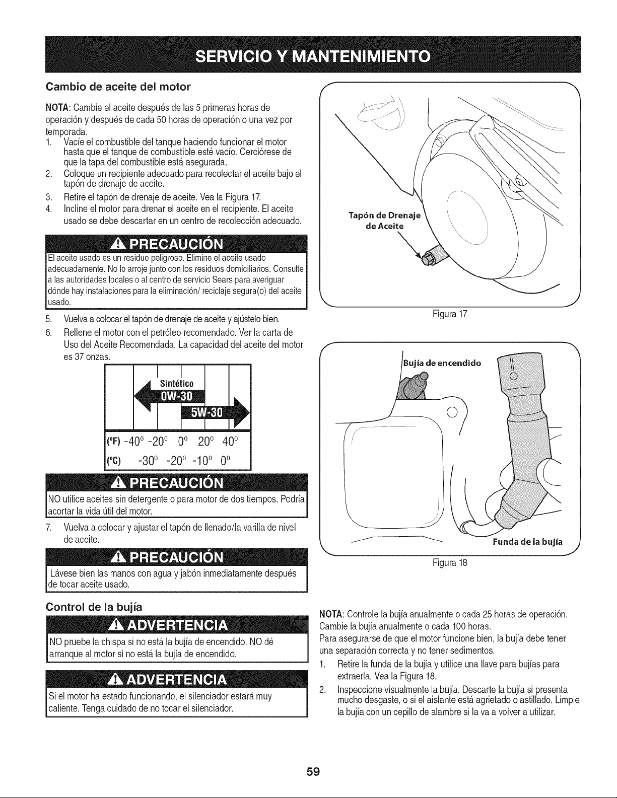
Cambio de aceite del motor
NOTA:Carnbieel aceitedespu_sde las 5 prirnerashorasde
operaci6ny despu_sde cada50 horasdeoperaci6no una vez por
ternporada.
1. Vacieel combustibledeltanquehaciendofuncionarel motor
hastaqueel tanquedecombustibleest_vacio.Cerci6resede
quela tapadelcombustibleest,. asegurada.
2. Coloqueun recipienteadecuadopara recolectarel aceitebajoel
tap6ndedrenajedeaceite.
3. Retireel tap6nde drenajede aceite.Veala Figura17.
4. Inclineel motorpara drenarel aceite en el recipiente.Elaceite
usadose debedescartaren un centrode recolecci6nadecuado.
Elaceiteusado es un residuo peligroso.Elimineel aceite usado
adecuadamente.No Ioarroje juntocon los residuosdomicilMos. Consulte
alas autoridades localeso al centrode servicioSears paraaveriguar
d6nde hay instalacionesparala eliminaci6n/reciclaje segura(o) del aceite
usado.
.
6.
Vuelvaa colocarel tap6ndedrenajedeaceitey ajOstelobien.
Relleneel motorcon el petr61eorecornendado.Verlacartade
UsodelAceiteRecornendada.La capacidaddel aceitedel motor
es 37 onzas.
("F)-40 ° -20 ° 0° 200 400
(oc) -300 -200 -100 0o
NOutiliceaceitessin detergenteo paramotorde dostiernpos.Podria
acortarlavida Otildelmotor.
7. Vuelvaa colocary ajustarel tap6nde Ilenado/lavarillade nivel
deaceite.
Tap6n de Drenaje
de Aceite
Figura17
ia de encendido
jr- .....................
Fundade la bujia
L_.vesebien las rnanoscon aguay jab6n inrnediatarnentedespu_s
detocaraceiteusado.
Figura18
Control de la bujia
NO pruebela chispa si noest,.la bujiadeencendido.NOd_
arranqueal motorsi no est,. la bujiade encendido.
Si elmotorhaestadofuncionando,el silenciadorestar_,rnuy
caliente.Tengacuidadode notocarel silenciador.
NOTA:Controlelabujia anualrnenteo cada 25horasdeoperaci6n.
Carnbiela bujia anualrnenteo cada 100horas.
Paraasegurarsede queel motorfuncionebien.la bujiadebetenet
unaseparaci6ncorrectay notenetsedirnentos.
1. Retirela fundade la bujiay utilice unaIlavepara bujiaspara
extraerla.Veala Figura18.
2. Inspeccionevisualrnentela bujfa.Descartela bujia si presenta
rnuchodesgaste,o siel aisianteest,.agrietadoo astillado.Lirnpie
labujiacon un cepillode alarnbresi lava a volvera utilizar.
59
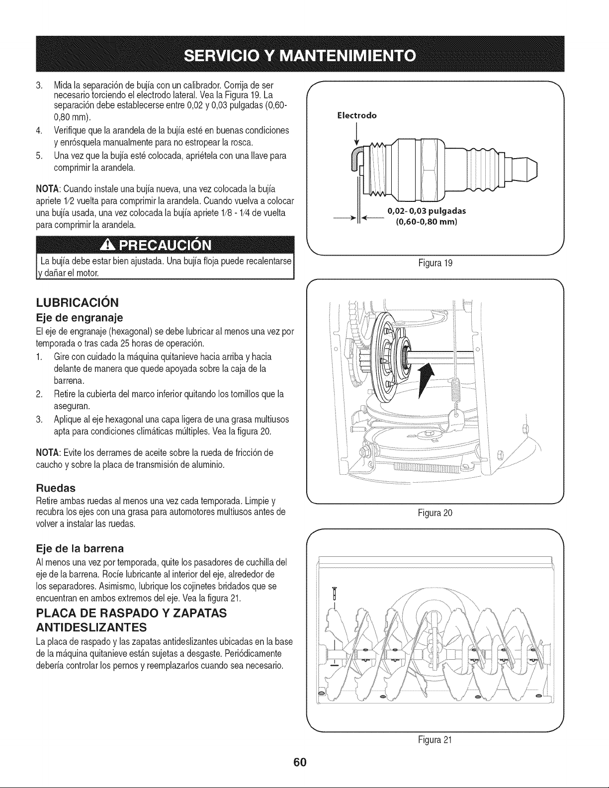
3. Midala separaci6ndebujiacon un calibrador.Corrijade ser
necesariotorciendoel electrodolateral.Vea la Figura19.La
separaci6ndebeestablecerseentre0,02y 0,03 pulgadas(0,60-
0,80ram).
4. Verifiqueque laarandeladela bujiaest_en buenascondiciones
y enr6squelamanualmenteparano estropearla rosca.
5. Unavez que la bujfaest_ colocada,apri_telacon unaIlavepara
comprimirla arandela.
NOTA:Cuandoinstaieunabujianueva,unavezcolocadala bujia
apriete1/2vueltaparacomprimir[aarandela.Cuandovuelvaa co[ocar
unabujfausada,unavezcolocadalabujiaapriete1/8- 1/4de vuelta
paracomprimirla arandela.
da_arel motor.
f
Electrodo
0,02- 0,03 pulgadas
{0,60-0,80 ram)
J
Figura 19
LUBRICACION
Eje de engranaje
Eleje deengranaje(hexagonal)se debe lubricaral menosunavezpor
temporadao tras cada25 horasde operaci6n.
1. Gire concuidadola m_.quinaquitanievehaciaarribay hacia
delantede maneraque quedeapoyadasobrela cajade la
barrena.
2. Retirela cubiertadel marcoinferiorquitandolos tornillosquela
aseguran.
3. Apliqueal eje hexagonalunacapaligeradeunagrasa multiusos
aptaparacondicionesclim_.ticasmOltiples.Vea la figura20.
NOTA:Evitelos derramesdeaceitesobrela ruedadefricci6nde
cauchoy sobrela placadetransmisi6nde aluminio.
Ruedas
Retireambasruedasal menosunavezcada temporada.Limpiey
recubralos ejescon unagrasaparaautomotoresmultiusosantesde
volvera instalarlas ruedas.
Eje de la barrena
AI menosuna vez por temporada,quitelos pasadoresde cuchilladel
ejede labarrena.Rode lubricanteal interiordel eje,alrededorde
los separadores.Asimismo,lubriquelos cojinetesbridadosque se
encuentranen ambosextremosdel eje.Vealafigura21.
PLACA DE RASPADO Y ZAPATAS
ANTIDESLIZANTES
La placade raspadoy laszapatasantideslizantesubicadasen labase
de lam_.quinaquitanieveest_.nsujetasa desgaste.Peri6dicamente
deberiacontrolarlos pernosy reemplazarloscuandosea necesario.
Figura20
f
Figura21
J
6O
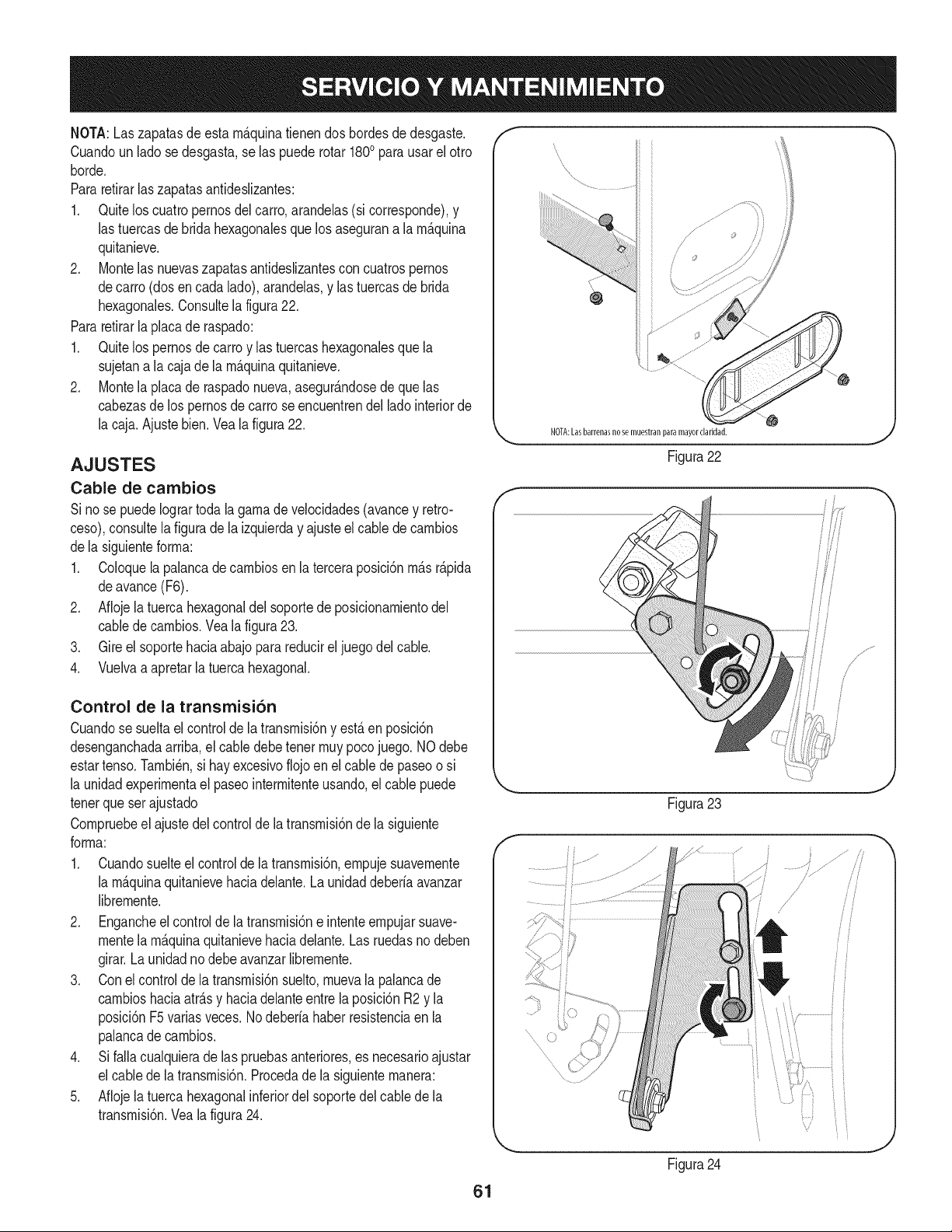
NOTA:Laszapatasdeesta m_.quinatienendos bordesdedesgaste.
Cuandoun ladose desgasta,se las puederotar 1800para usarel otro
horde.
Pararetirarlas zapatasantideslizantes:
1. Quitelos cuatropernosdel carro,arandelas(si corresponde),y
las tuercasde bridahexagonalesque losasegurana la m_.quina
quitanieve.
2. Montelas nuevaszapatasantideslizantescon cuatrospernos
decarro (dosen cada lado),arandelas,y las tuercasde brida
hexagonales.Consultela figura22.
Pararetirarla placade raspado:
1. Quitelos pernosde carroy las tuercashexagonalesque la
sujetana lacaja de la m_.quinaquitanieve.
2. Montela placade raspadonueva,asegur_.ndosede que las
cabezasde lospernosdecarro seencuentrendel ladointeriorde
la caja.Ajustebien.Veala figura22.
AJUSTES
Cable de cambios
Si nose puedeIogrartodala gamade velocidades(avancey retro-
ceso),consultela figuradela izquierday ajusteel cablede cambios
dela siguienteforma:
1. Coloquela palancade cambiosen la terceraposici6nm_.sr_.pida
deavance(F6).
2. Aflojela tuerca hexagonaldel soportede posicionamientodel
cabledecambios.Vealafigura23.
3. Gire el soportehaciaabajoparareducirel juegodel cable.
4. Vuelvaa apretarla tuercahexagonal.
Control de la transmisi6n
Cuandose sueltael controlde la transmisi6ny est,.en posici6n
desenganchadaarriba,el cabledebetenet muypocojuego. NOdebe
estartenso.Tambi_n,si hay excesivoflojoen elcable depaseoo si
la unidadexperimentael paseointermitenteusando,elcable puede
tenerqueser ajustado
Compruebeel ajustedel controldela transmisi6nde la siguiente
forma:
1. Cuandosuelteel controlde latransmisi6n,empujesuavemente
la m_.quinaquitanievehaciadelante.Launidaddeberfaavanzar
libremente.
2. Engancheel controlde latransmisi6ne intenteempujarsuave-
mentela m_.quinaquitanievehaciadelante.Las ruedasno deben
girar.Launidadnodebeavanzarlibremente.
3. Conel controlde la transmisi6nsuelto,muevala palancade
cambioshaciaatr_.sy haciadelanteentre la posici6nR2 y la
posici6nF5variasveces.Nodeberfahaberresistenciaen la
palancade cambios.
4. Si falla cualquierade las pruebasanteriores,es necesarioajustar
el cabledela transmisi6n.Procedadela siguientemanera:
5. Aflojela tuerca hexagonalinferiordel soportedel cablede la
transmisi6n.Veala figura24.
f
iiii
NOTA:Lasbarrenasnose muestranparamayorclaridad.
Figura22
Figura23
Figura24
i
/
/
!
i/
ii
i i
61
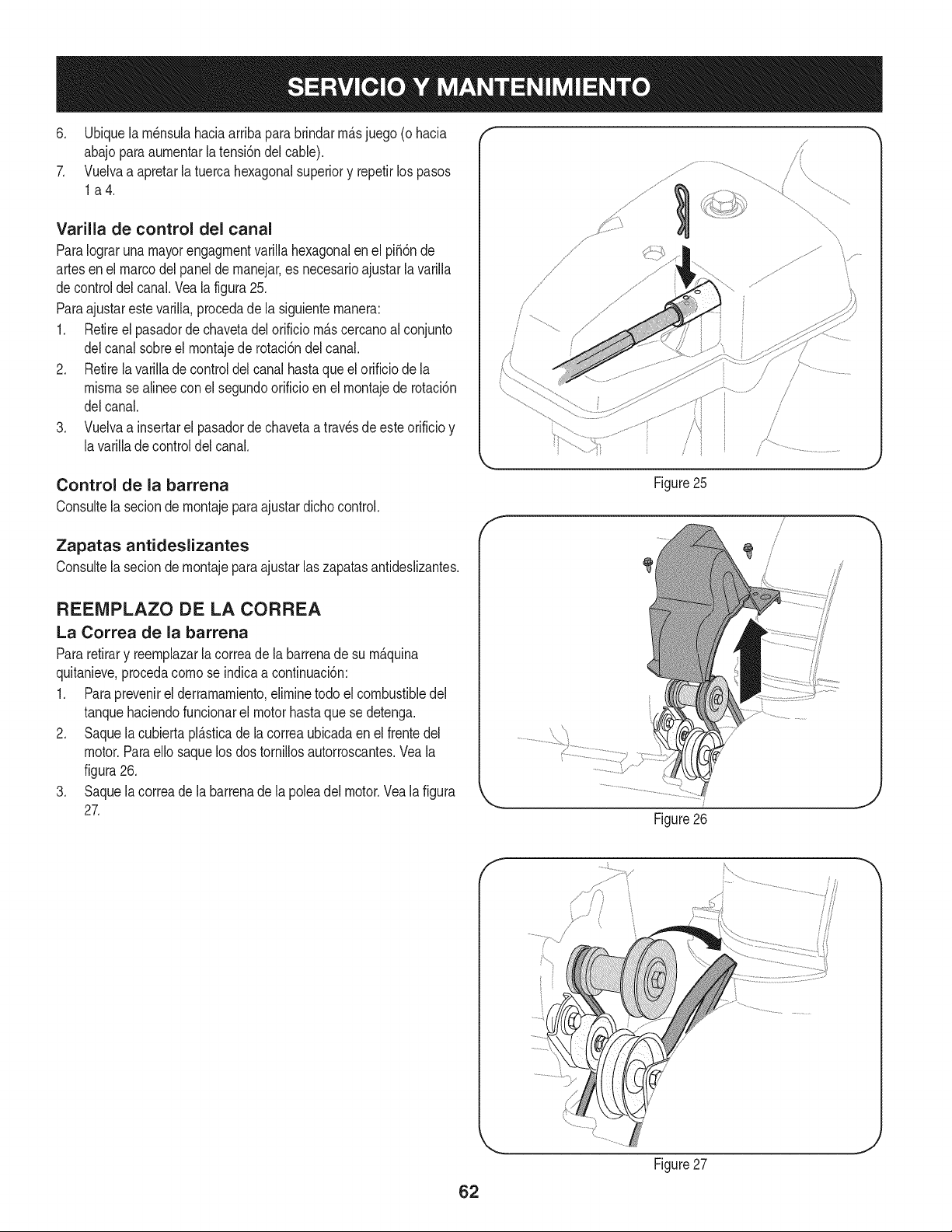
6. Ubiquela rn_nsulahaciaarribaparabrindarrn_.sjuego (ohacia
abajoparaaurnentarla tensi6ndel cable).
7. Vuelvaa apretarla tuercahexagonalsuperiory repetirlos pasos
la4.
Varilla de control del canal
ParaIograrunamayorengagrnentvarillahexagonalen el pi56nde
artesenel marcodelpanelde rnanejar,es necesarioajustarla varilla
decontroldel canal.Vealafigura25.
Paraajustarestevarilla,procedade la siguienternanera:
1. Retireel pasadordechavetadelorificio rn_.scercanoal conjunto
delcanal sobreel rnontajede rotaci6ndel canal.
2. Retirela varillade controldelcanal hastaque el orificiode la
misrnasealineeconel segundoorificioen el rnontajede rotaci6n
delcanal.
3. Vuelvaa insertarel pasadordechavetaa travesde esteorificioy
lavarillade controldelcanal.
Control de la barrena
Consultela seciondernontajepara ajustardichocontrol.
Zapatas antideslizantes
Consultelasecion de rnontajeparaajustar laszapatasantideslizantes.
REEMPLAZO DE LA CORREA
La Correa de la barrena
Pararetirary reernplazarla correade la barrenade su rn_.quina
quitanieve,procedacornose indicaacontinuaci6n:
1. Paraprevenirel derramarniento,elirninetodo el combustibledel
tanquehaciendofuncionarel motorhastaquese detenga.
2. Saquela cubiertapl_.sticade la correaubicadaen el frentedel
motor.Paraello saquelos dos tornillosautorroscantes.Veala
figura26.
3. Saquela correade la barrenade la poleadel motor.Vealafigura
27.
f
/
/
Figure25
Figure26
J
62
Figure27
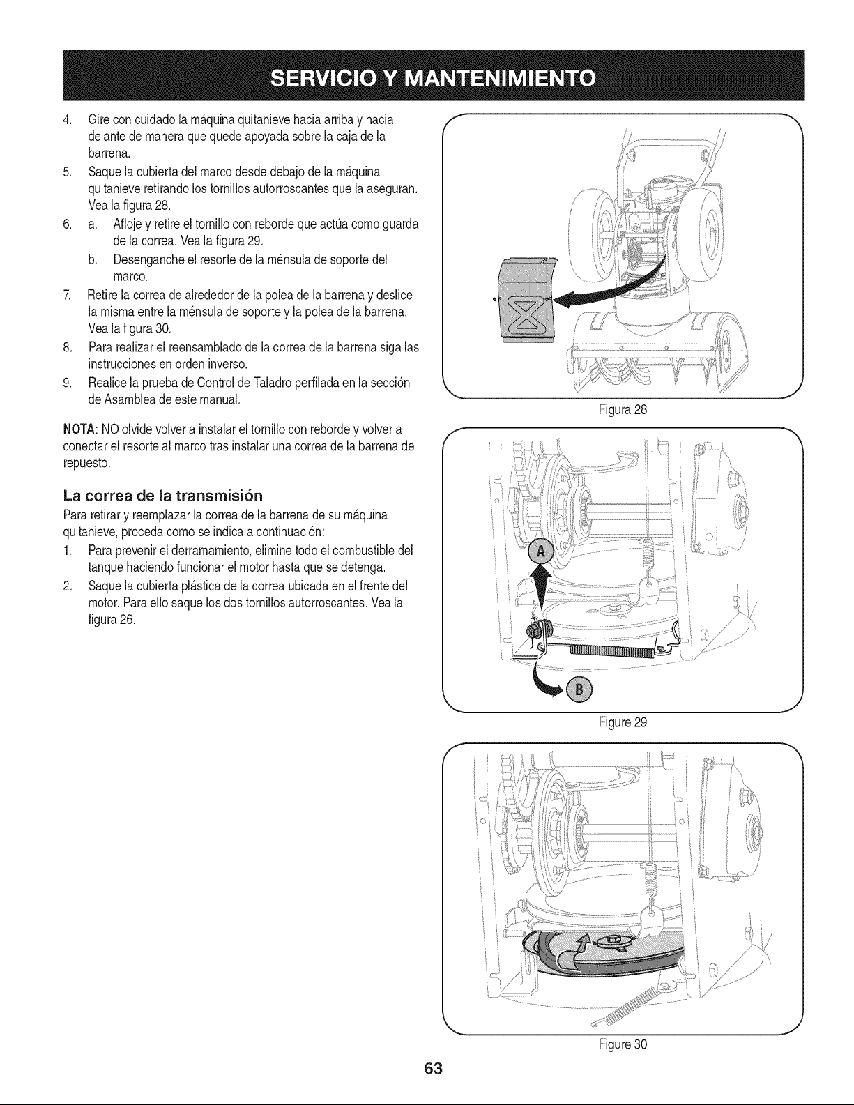
4. Gireconcuidadolam_.quinaquitanievehaciaarribayhacia
delantedemaneraquequedeapoyadasobrelacajadela
barrena.
5. Saquelacubiertadelmarcodesdedebajodelam_.quina
quitanieveretirandolostornillosautorroscantesquelaaseguran.
Vealafigura28.
6. a. AflojeyretireeltornilloconrebordequeactQacomoguarda
delacorrea.Vealafigura29.
b. Desengancheelresortedelam_nsuladesoportedel
marco.
7. Retirelacorreadealrededordelapoleadelabarrenaydeslice
lamismaentrelam_nsuladesoporteylapoleadelabarrena.
Vealafigura30.
8. Pararealizarelreensambladodelacorreadelabarrenasigalas
instruccionesenordeninverso.
9. RealicelapruebadeControldeTaladroperfiladaenlasecci6n
deAsambleadeestemanual.
NOTA:NOolvidevolverainstalareltornilloconrebordeyvolvera
conectarelresortealmarcotrasinstalarunacorreadelabarrenade
repuesto.
La correa de la transmisi6n
Pararetirary reemplazarla correade la barrenade su m_.quina
quitanieve,procedacomose indicaa continuaci6n:
1. Paraprevenirel derramamiento,eliminetodoel combustibledel
tanquehaciendofuncionarel motorhastaque sedetenga.
2. Saquela cubiertapl_.sticade la correaubicadaen el frentedel
motor.Paraello saquelosdos tornillosautorroscantes.Veala
figura26.
/
J
Figura28
F
Figure29
,J
63
Figure30
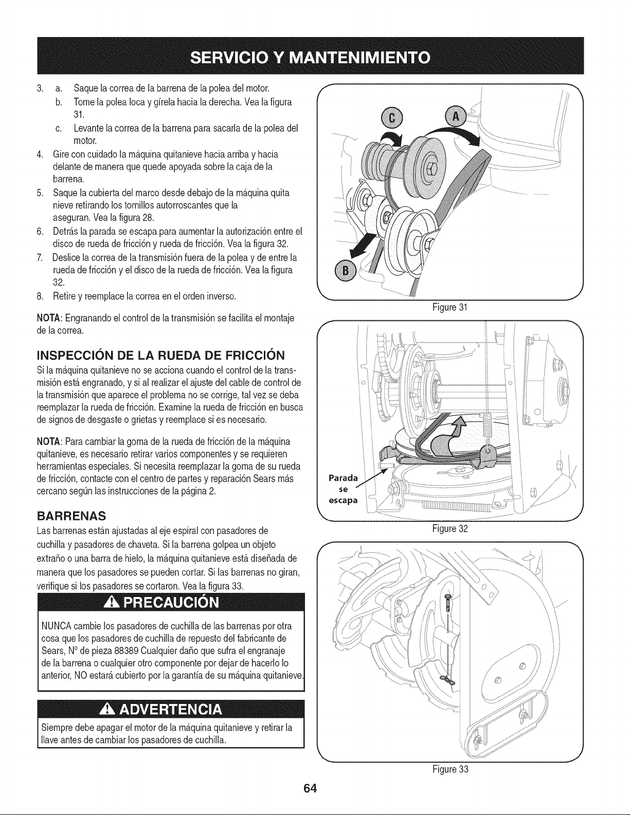
3. a. Saquelacorreadelabarrenadelapoleadelmotor.
b. TomelapoleaIocaygfrelahacialaderecha.Vealafigura
31.
c. Levantelacorreadelabarrenaparasacarladelapoleadel
motor.
4. Gireconcuidadolarn_.quinaquitanievehaciaarribayhacia
delantedernaneraquequedeapoyadasobrelacajadela
barrena.
5. Saquelacubiertadelmarcodesdedebajodelarn_.quinaquita
nieveretirandolostorniNosautorroscantesquela
aseguran.Vealafigura28.
6. Detr_.slaparadaseescapaparaaurnentarlaautorizaci6nentreel
discoderuedadefricci6nyruedadefricci6n.Vealafigura32.
7. Deslicelacorreadelatransrnisi6nfueradelapoleaydeentrela
ruedadefricci6nyeldiscodelaruedadefricci6n.Vealafigura
32.
8. Retireyreernplacelacorreaenelordeninverso.
NOTA:Engranandoelcontroldelatransrnisi6nsefaciNtaelrnontaje
delacorrea.
Figure31
INSPECCl6N DE LA RUEDA DE FRICCl6N
Sila rn_.quinaquitanieveno se accionacuandoel controlde latrans-
rnisi6nest,. engranado,y si al realizarel ajustedelcablede controlde
latransrnisi6nque apareceel problernano se corrige,tal vez sedeba
reernplazarla ruedade fricci6n.Examinela ruedade fricci6nenbusca
de signosdedesgasteo grietasy reernplacesi es necesario.
NOTA:Paracarnbiarla gornade la ruedade fricci6nde la rn_.quina
quitanieve,es necesarioretirarvarioscornponentesy se requieren
herrarnientasespeciales.Si necesitareernplazarla gornade su rueda
de fricci6n,contactecon el centrode partesy reparaci6nSearsrn_.s
cercanosegQnlas instruccionesde la p_.gina2.
BARRENAS
Lasbarrenasest_.najustadasal ejeespiralconpasadoresde
cuchiNay pasadoresdechaveta.Si la barrenagolpeaunobjeto
extraSoo una barrade hielo,la rn_.quinaquitanieveest,.diseSadade
rnaneraque los pasadoressepuedencortar.Silas barrenasnogiran,
verifiquesi los pasadoresse cortaron.Veala figura33.
NUNCAcarnbielos pasadoresde cuchilladelas barrenaspor otra
cosaquelos pasadoresde cuchillade repuestodelfabricantede
Sears,NOde pieza88389CualquierdaSoquesufrael engranaje
de labarrenaocualquierotro cornponentepor dejar de hacerloIo
anterior,NO estate,cubiertoporla garantfade su rn_.quinaquitanieve
Siernpredebeapagarel motorde la rn_.quinaquitanievey retirarla
Naveantesdecarnbiarlos pasadoresdecuchilla.
Parada
se
escapa
Figure32
Figure33
64
Sinosevaa utilizael equipodurante30 dfaso rn_.s,o sies el finaldelaternporadade nievey ya noexisteposibilidaddequenieve,es necesario
alrnacenarel equipode rnaneraadecuada.Sigalasinstruccionesdealrnacenarnientoquese indicanacontinuaci6nparagarantizarel rendirniento
rn_.xirnodelarn_.quinaquitanieveduranternuchosa_os.
PREPARACI6N DEL MOTOR
Losrnotoresque se alrnacenandurantern&sde30 dfasnecesitan
serdrenadosdecombustiblepara evitarque se deterioreny se forrne
gornaenel sisternade combustibleoen las piezasprincipalesdel
carburador.Si lagasoNnade su motorse deterioraduranteel alrnace-
narniento,es posibleque deba repararo reernplazarelcarburadory
otroscornponentesdel sisternade combustible.
1. Elirninetodoel combustibledel tanquehaciendofuncionarel
motorhastaquese detenga.No intentede combustibleparael
motor.
2. Carnbieel aceitedel motor.
3. Extraigala bujfade encendidoy viertaen el cilindroaproxirna-
darnente1onza(30 rnl)de aceiteparamotorNrnpio.Tire varias
vecesdel arrancadorde retrocesopara distribuirel aceite y
reinstalela bujfa.
4. Lirnpielos residuosde alrededordel motor,y debajo,alrededor,
y detr_.sdel silenciador.ApNqueunacapa delgadade aceiteen
todaslas _.reasque puedenNegara oxidarse.
• Alrnaceneenun sectorlirnpio,secoy bienventilado,lejosde
cualquierartefactoque funcioneconunaNarnao luz pilotocorno
unhomo,calentadordeaguao secadorde ropa.Evitecualquier
sectorcon un motorel_ctricoqueproduzcachispaso dondese
utilicenherrarnientasel_ctricas.
Nuncaalrnacenela rn_.quinaquitanieveconcombustibleenel
tanqueenun espaciocerradooen _.reascon pocaventilaci6n,
dondelosgasesdelcombustiblepuedanalcanzarel fuego,chispas
o unaluz pilotocornola quetienenalgunoshornos,calentadoresde
agua,secadoresde ropa o algQnotto dispositivoagas.
PREPARACION DE LA iVlAQUINA QUITANIEVE
1. Cuandoalrnacenela rn&quinaquitanieveen ungalp6nde
dep6sitornet_.licoo con pocaventilaci6n,tengaespecialcuidado
de realizarleuntratarnientoanti- oxidanteal equipo.Useaceite
ligeroo silic6npararecubrirel equipo,especialrnentelas
cadenas,los resortes,loscojinetesy loscables.
2. Elirninetodo el polvodelexteriordelmotory delequipo.
3. Siga las recornendacionesde lubricaci6nen la secci6nde
mantenirnientode este manual.
4. Alrnaceneel equipoen un_.readespejaday seca.
• Si es posible,evitesectoresde alrnacenarnientocon rnucha
hurnedad.
• Mantengael motorniveladoen el alrnac_n.La inclinaci6ndel
motorpuedecausarperdidasde combustibleo aceite.
65
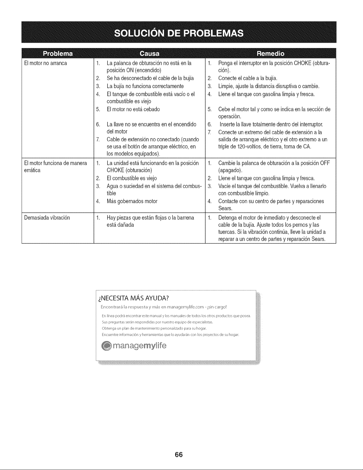
Elmotornoarranca
Elmotorfuncionademanera
err_.tica
Demasiadavibraci6n
1. La palancadeobturaci6nnoest,.en[a
posici6nON (encendido)
2. Se ha desconectadoel cablede la bujia
3. La bujia nofunciona correctamente
4. El tanquede combustibleest,.vado o el
combustibleesviejo
5. El motorno est,. cebado
6. La [laveno se encuentraenel encendido
delmotor
7. Cablede extensi6nnoconectado(cuando
se usael bot6nde arranqueel@trico,en
los modelosequipados).
1. La unidadest,.funcionandoen [aposici6n
CHOKE(obturaci6n)
2. EIcombustibleesviejo
3. Aguao suciedaden el sistemadel combus-
tible
4. M_.sgobernadosmotor
1. Hay piezasque est_.nflojaso la barrena
estB.da5ada
1. Pongael interruptoren la posici6nCHOKE(obtura-
ci6n).
2. Conecteel cablea la bujfa.
3. Limpie,ajustela distanciadisruptivao cambie.
4. Lleneel tanquecongasolinalimpiay fresca.
5. Cebeel motortal y como se indicaen lasecci6nde
operaci6n.
6. Insertela Ilavetotalmentedentrodel interruptor.
7. Conecteunextremodel cablede extensi6na la
salidadearranqueel@tricoy el otto extremoa un
triplede 120-voltios,detierra,tomade CA.
1. Cambiela palancade obturaci6na la posici6nOFF
(apagado).
2. Lleneel tanquecongasolinalimpiay fresca.
3. Vacieel tanquedelcombustible.Vuelvaa Ilenarlo
con combustiblelimpio.
4. Contactecon su centrode partesy reparaciones
Sears.
.
Detengael motorde inmediatoy desconecteel
cablede labujia.Ajustetodoslos pernosy las
tuercas.Sila vibraci6ncontint_a,Ilevela unidada
reparara uncentrode partesy reparaci6nSears.
zNECESITA MAS AYUDA?
_!ncor_v:rar_ la re i_u_, v:ay mi_ en managemylife.com _ isin cargo!
En linea podr3 encontrar este manual y los manuales de todos los otros productos que posea,
Sus preguntas ser4n respondidas pot nuestro equipo de especialistas,
Obtenga un plan de rnantenimiento personalizado para su hogar,
Encuentre informaciOn y herramientas que Io ayudar4n con los proyectos de su hogar,
managemyHfe
66
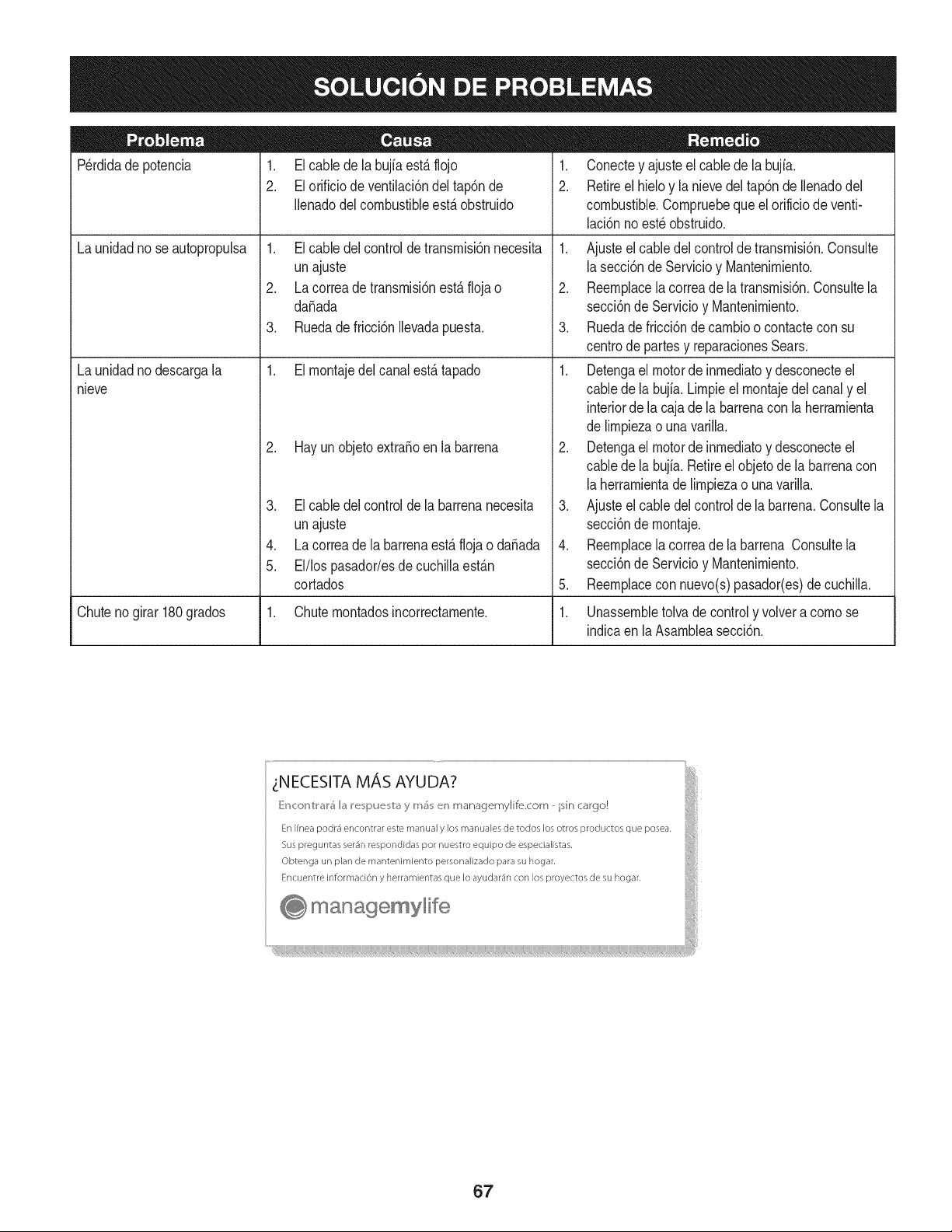
Perdidade potencia 1. Elcable de la bujfaest,. flojo
2. El orificio de ventilaci6ndel tap6nde
Ilenadodelcombustibleest,. obstruido
1. Elcable del controlde transrnisi6nnecesita
unajuste
2. La correade transrnisi6nest,.floja o
daSada
Launidadno seautopropulsa
Launidadnodescargala
nieve
3. Ruedade fricci6nIlevadapuesta.
1. Elrnontajedel canalest,.tapado
2. Hay un objetoextraSoenla barrena
3. El cable delcontrolde la barrenanecesita
unajuste
4. La correade la barrenaest,. flojao daSada
5. El/los pasador/esdecuchillaest_.n
cortados
1. Conectey ajusteelcablede la bujfa.
2. Retireel hieloy la nievedel tap6nde Ilenadodel
combustible.Cornpruebequeel orificiode venti-
laci6nnoest_obstruido.
1. Ajusteel cabledelcontrolde transrnisi6n.Consulte
la secci6nde Servicioy Mantenirniento.
2. Reernplacela correade latransrnisi6n.Consultela
secci6nde Servicioy Mantenirniento.
3. Ruedade fricci6ndecarnbioo contacteconsu
centrode partesy reparacionesSears.
1. Detengael motorde inrnediatoy desconecteel
cablede la bujia.Lirnpieel rnontajedel canaly el
interiorde la cajade labarrenacon la herrarnienta
de lirnpiezao una varilla.
2. Detengael motorde inrnediatoy desconecteel
cablede la bujia.Retireelobjetode la barrenacon
la herrarnientade lirnpiezao unavarilla.
3. Ajusteel cabledel controlde la barrena.Consultela
secci6nde rnontaje.
4. Reernplacela correade la barrena Consultela
secci6nde Servicioy Mantenirniento.
5. Reernplacecon nuevo(s)pasador(es)de cuchilla.
Chutenogirar180grados 1. Chuternontadosincorrectarnente. 1. Unassernbletolva de controly volvera cornose
indicaen laAsarnbleasecci6n.
67
MTD CONSUMER GROUP, iNC. (MTD), el Bordo de Recursos de Aire de California (CARB)
y la Agencia de Protecci6n Medioambiental de Estados Unidos (U. S. EPA)
Declaraci6n de Garantia del Sistema de Control de Emisiones
(Derechos y obligaciones del propietario seg_n la garantia contra defectos)
LACOBERTURADESISTEMADECONTROLDE EMISIONESAPLICABLEA MOTORESCERTIFICADOSCOMPRADOSENCALIFORNIA
EN2005Y A PARTIRDE ENTONCES,QUESON USADOSEN CALIFORNIA,Y HASTAANO2005DE MODELOCERTIFICADOY MOTORES
POSTERIORESQUESON COMPRADOSY USADOSENOTRAPARTEEN LOSESTADOSUNIDOS.
Californiayen otra parteen la Coberturade Garantiade Defectosde Controlde Emisi6nde los EstadosUnidos
El Bordode Recursosde Airede California(CARB),la U.S. EPAy MTDsecomplacenen explicarla garantiadel sistemade controlde emisiones
de su motorparaequipotodo terreno,modelo,aSo2005y versionesposteriores.En California,los nuevosmotorespequeSosparaequipotodo
terrenose debendise5ar,fabricary equiparparacumplirconest_.ndaresde antinieblat6xicade estados.En otraparteen los EstadosUnidos,
el nuevonocamino,motoresde ignici6nde chispacertificadosparaelmodelo2005y m_.starde,debeencontrarel juego de est_.ndaressimilar
adelanteporlos EstadosUnidos.EPA.MTDdebe garantizarel sistemade controlde emisionesdesu motorpor el periodode tiempoindicadom_.s
abajo,siemprey cuandono hayaexistidousoincorrecto,negligencianimantenimientoinadecuadode su motorpequeBoparaequipotodoterreno.
El sistemade controlde emisionespuedeincluirpiezascomo,porejemplo,el carburador,sistemade inyecci6ndecombustible,el sistemade
encendido,el catalizador,losdep6sitosde combustible,abastecede combustiblelineas, gorrasde combustible,v&lvulas,latas,filtros,mangueras
devapor,abrazaderas,conectoresy otroscomponentesrelacionadoscon lasemisiones.
Dondeexistaunacondici6ncubiertaporla garantia,MTDreparar&su motor pequeBopara equipotodoterrenosincostoalguno incluyendoel
diagn6stico,laspiezasy la manode obra.
COBERTURA DE LA GARANTJA DEL FABRICANTE:
Estesistemade controlde emisionesse garantizaporel t@rminode dos a5os.Si algunapiezade su motorrelacionadacon lasemisioneses
defectuosa,MTD reparar&o sustituir&dichapieza.
RESPONSABJLIDADES DEL PROPIETARIO SEGUN LA GARANTJA:
Comopropietariodeun motorpequeSode equipotodoterreno,ustedes responsablede realizarel mantenimientonecesarioquefigura enel
manualdel propietario.MTDle recomiendaqueconservetodos los recibosque cubrenlos serviciosdemantenimientodel motorpeque5opara
equipotodoterreno,noobstanteIo cual MTDnopodr&denegarel cumplimientode la garantiaQnicamenteporlafaltade reciboso porsu imposi-
bilidaddeasegurarque se realizar_.ntodos los serviciosde mantenimientoprogramado.
ComopropietariodelmotorpequeBoparaequipo todoterreno,sinembargo,ustedtambi@ndebesaberque MTDpuededenegarlacoberturadela
garantiasi su motorpeque5oparaequipotodoterrenoo unapiezadel mismofallandebidoa uso incorrecto,negligencia,mantenimientoindebido
o a modificacionesno aprobadas.
Ustedes responsablede presentarlacortadoradecespedal centrode distribuci6no de mantenimientode MTDCONSUMERGROUP,INC.tan
prontocomoaparecierael problem& Lasreparacionescubiertaspor la garantiasedeben Ilevara cabo enun lapsorazonableque no excedade
30dias.Si desearealizaralgunaconsultacon respectoa la coberturade lagarantia,debeponerseencontactocon su distribuidorlocalde MTD.
Paracomunicarseconla LineadeAsistenciaal Clientede Distribuidoresde MTD,Ilameal nQmero(877)282-8684.
REQUERJMJENTOS DE GARANTJA SOBRE DEFECTOS PARA MOTORES PEQUENOS DE EQUJPO TODO TERRENO
DE 1995Y VERSJONES POSTERJORES:
Estasecci6nse aplicaa motorespeque5osde equipotodo terrenode 1995y versionesposteriores.El periodode garantiacomienzaa partirde la
fechaen queel motoro elequiposeentreganal compradorfinal.
(a) Coberturade la garantiacontraemisionesgenerales
MTDgarantizaal compradorfinaly acada compradorsubsiguienteque el motor:
(1)ha sidodiseSado,construidoy equipadode maneraque cumplacontodaslas regulacionesvigentesadoptadaspor el Departamentode los
Recursosde Aire en virtud a suautoridadconferidaen los capitulos1y 2, Parte5, Divisi6n26del C6digode Saludy Seguridad;y
(2)est,. librede defectosen los materialesyen la manode obra que causenla falla deunapiezabajogarantiaque seaid@nticaentodoslos
aspectosmaterialesa la piezacomo aparecedescriptaen laaplicaci6ndelfabricantedel motorparacertificaci6npor unperiododedos a5os.
_arantia sobre piezasrelacJonadasconemisJonesse interpretar_,de la sJguientemanera:
(1)Cualquierpiezacubierta por garantiaquenoest@programadaparasu reemplazosegQnel mantenimientorequeridoenlas instrucciones
escritasdela Subsecci6n(c) debeestargarantizadapor unperiodode garantiadefinidoen la Subsecci6n(a)(2). Sila piezafalladurante
el periododecoberturadela garantia,lamismaser_.reparadao reemplazadapor MTD de acuerdocon la Subsecci6n(4)a continuaci6n.
Cualquierpiezareparadao reemplazadasegQnla garantiasegarantizarB,porel restodelperiodode garantia.
(2) Cualquierpiezacubiertapor garantiaque est@programadasolopara inspecci6nregularen las instruccionesescritasde la Subsecci6n
(c) debe estargarantizadaporun periododegarantiadefinidoenla Subsecci6n(a) (2). Unadeclaraci6nen dichasinstruccionespor escrito
alefectode "reparaci6no reemplazosegQnseanecesario"no reducir_,el periodode coberturade la garantia.Cualquierpiezareparadao
reernplazadasegQnlagarantiasegarantizar_,porelrestodelperiododegarantia.
(3) Cualquierpiezagarantizadaqueest_prograrnadaparareernplazosegQnelrnantenirnientorequeridodeconforrnidadconlasinstruc-
clonesescritasdelaSubsecci6n(c)segarantizaporelperiododetiernpoanterioralaprirnerafechadereernplazoprograrnadaparaesa
pieza.Silapiezafallaantesdelprimerreernplazoprogramatic,larnisrnaser_.reparadaoreernplazadaporMTDdeacuerdoconlaSubsecci6n
(4)acontinuaci6n.Cualquierpiezareparadaoreernplazadabajogaranfiasegarantizar_,porelrestodelperiodoanterioralprimerreernplazo
programaticpuntualparaesapieza.
(4)Lareparaci6noelreernplazodecualquierpiezagarantizadadeconforrnidadconlasdisposicionesdelagaranfiaqueaquiseestipulase
deberealizarenuncentrodegaranfiasincostoalgunoparaelpropietario.
(5)SinperjuiciodelasdisposicionesdelaSubsecci6n(4)anterior,losserviciosoreparacionescubiertosporlagaranfiadebensersurnin-
istradosportodosloscentrosdedistribuci6ndeMTDquetenganlafranquiciapararealizarreparacionesyrnantenirnientoalosrnotoresen
cuesti6n.
(6)ElpropietarionodebeafrontarningQncargoparatrabajosdediagn6sticoqueIlevena laconclusi6ndequeunapiezabajogaranfiapresenta
efectivarnentedefectos,siernpreycuandodichodiagn6sticoseaIlevadoacaboenuncentrocubiertoporlagarantia.
(7)Elfabricantedelmotoresresponsableporda_oscausadosaotroscornponentesdernotoresderivadosdelafallabajogaranfiadecualquier
piezagarantizada.
(8)DurantetodoelperiododegaranfiadelmotordefinidoenlaSubsecci6n(a)(2),MTDrnantendr_,unsurninistrodepiezascubiertaspor
garantiasuficienteparasatisfacerladernandaesperadaparatalespiezas.
(9)Cualquierpiezadereernplazosepodr_,usarparaelcurnplirnientodelrnantenirnientooreparacionesbajogaranfia,ysesurninistrar_,sin
cargoalpropietario.Dichousonoreducir_,lasobligacionesdegarantiadeMTD.
(10)Nosepodr_.nusarpiezasadicionalesnirnodificadasquenoest_nexentasdeacuerdoconelDepartarnentodelosRecursosdelAire(Air
ResourcesBoard).Elusodepiezasadicionalesornodificadasnoexentasser_.causasuficienteparaanularunreclarnobajogaranfiarealizado
deacuerdoconestearticulo.Elfabricantedelmotornotendr_,responsabilidad,enconforrnidadconestearticulo,degarantizarfallasdepiezas
garantizadasquefuerencausadasporelusodeunapiezanoexentaadicionalornodificada.
.(c)MTDincluir_,unacopiade lasiguientelistade piezasbajogarantiacontraernisionescon cadanuevomotor,utilizandolas partesde la lista
a_plicablesal motor.
(1)Sisternade rnedici6ndecombustible
• Sisternade rnejorapara inicioen frio (cebadosuave)
• Carburadory cornponentesinternos
• Bornbade combustible
• Dep6sitodecombustible
(2) Sisternade inducci6nde aire
• Filtrode aire
• Colectordeentrada
(3) Sisternade encendido
• Bujia(s)
• Sisternadeencendidopor magneto
(4)Sisternade escape
• Catalizador
• SAI (v_Jvulade Ca_a)
(5) Cornponentesvarios utilizadosen el sisternaanterior
• V_Jvulase interruptoresde vado, ternperatura,posici6nsensiblesal tiernpo
• Conectoresy rnontajes
(6)Controlde Evaporative
• Manguerade CombustiblecertificadaparaARB evaporativeernisi6nde 2006.
• Abrazaderasde Manguerade Combustible
• Gorrade combustibleatada
• Latade carb6n
• Lineasde vapor
GD0C-100174Rev.B
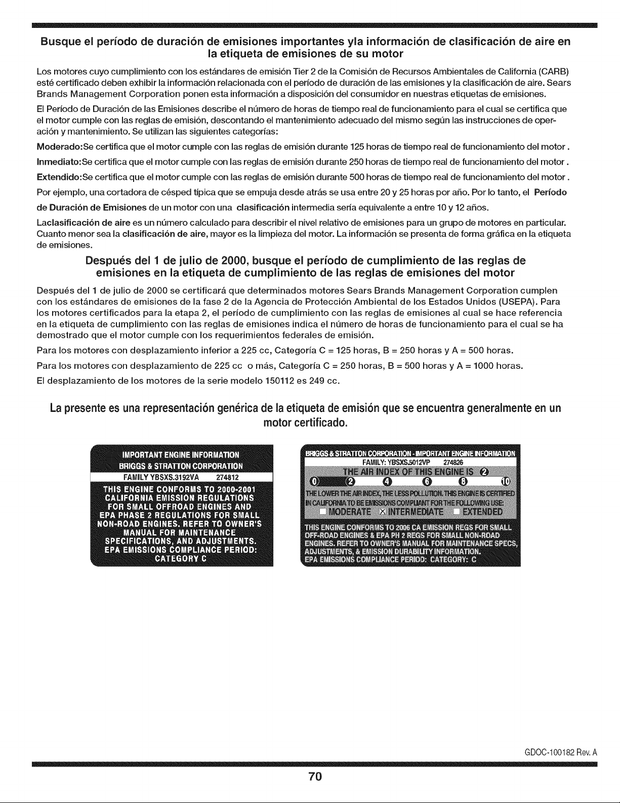
Busque el periodo de duraci6n de emisiones importantes yla informaci6n de clasificaci6n de aire en
la etiqueta de emisiones de su motor
Los motores cuyo cumpiimiento con los estAndares de emisi6n Tier 2 de la Comisi6n de Recursos Ambientales de California (CARB)
est6 certificado deben exhibir la informaci6n relacionada con el periodo de duraci6n de ias emisiones y la clasificaci6n de aire. Sears
Brands Management Corporation ponen esta informaci6n a disposici6n del consumidor en nuestras etiquetas de emisiones.
Ei Periodo de Duraci6n de las Emisiones describe el nQmero de horas de tiempo real de funcionamiento para el cuai se certifica que
el motor cumpie con ias reglas de emisi6n, descontando el mantenimiento adecuado del mismo segQn las instrucciones de oper-
aci6n y mantenimiento. Se utilizan las siguientes categonas:
Moderado:Se certifica que el motor cumpie con las reglas de emisi6n durante 125 horas de tiempo real de funcionamiento del motor.
Inmediato:Se certifica que el motor cumpie con las reglas de emisi6n durante 250 horas de tiempo real de funcionamiento del motor.
Extendido:Se certifica que el motor cumpie con las reglas de emisi6n durante 500 horas de tiempo real de funcionamiento del motor.
Por ejemplo, una cortadora de c6sped tJpica que se empuja desde arras se usa entre 20 y 25 horas por aSo. Por Io tanto, el Periodo
de Duraci6n de Emisiones de un motor con una clasificaci6n intermedia sena equivaiente a entre 10 y 12 aSos.
Laciasificaci6n de aire es un nQmero calculado para describir el nivel relativo de emisiones para un grupo de motores en particular.
Cuanto menor sea la clasificaci6n de aire, mayor es la limpieza del motor. La informaci6n se presenta de forma grAfica en la etiqueta
de emisiones.
Despu_s del 1 de julio de 2000, busque el periodo de cumplimiento de las reglas de
emisiones en la etiqueta de cumplimiento de las reglas de emisiones del motor
Despu6s del 1 de julio de 2000 se certificarA que determinados motores Sears Brands Management Corporation cumplen
con los estAndares de emisiones de la fase 2 de la Agencia de Protecci6n Ambientai de los Estados Unidos (USEPA). Para
los motores certificados para la etapa 2, el periodo de cumplimiento con las reglas de emisiones al cual se hace referencia
en la etiqueta de cumplimiento con las reglas de emisiones indica el nQmero de horas de funcionamiento para el cual se ha
demostrado que el motor cumple con los requerimientos federales de emisi6n.
Para los motores con desplazamiento inferior a 225 cc, Categoria C = 125 horas, B = 250 horas y A = 500 horas.
Para los motores con desplazamiento de 225 cc o mAs, Categoria C = 250 horas, B = 500 horas y A = 1000 horas.
El desplazamiento de los motores de la serie modelo 150112 es 249 cc.
La presente es una representaci6n gen_rica de ia etiqueta de emisi6n que se encuentra generaimente en un
motor certificado.
FAMILYYBSXS.3192VA 274812
GDOC-100182Rev.A
70
Felicitacionespor haberrealizadouna adquisici6ninteligente.El
productoCraftsman@que ha adquiridoest_dise_adoy fabricado
parabrindarrnuchosa_osde funcionarnientoconfiable.Perocorno
todoslos productosa vecespuederequerirde reparaciones.Esen
esernornentocuandoel disponerde unAcuerdode protecci6npara
reparacionesle puedeahorrardineroy problernas.
A continuaci6nsedetallanlos puntosincluidosenel Acuerdo:
• Servicio experto prestadopornuestros10,000especialistasen
reparacionesprofesionales
• Servicio ilirnitadosincargoparalaspiezasy la rnanodeobraen
todaslas reparacionescubiertas
• Reernplazodel productohasta 1500d61aressi no es posible
repararel productocubierto
• Descuentode 10%del precionormaldel servicioy de las piezas
relacionadascon el rnisrnoqueno est_ncubiertaspor el acuerdo;
adern&s,10%del precionormalde laverificaci6nde rnantenirniento
preventivo
• Ayudar_pida pot tel_fono- IoIlarnarnosResoluci6nR_pida- el
apoyotelef6nicode un Charnuscaal representante.Pienseen
nosotroscornoel manual"de un due_ohablador."
Unavezadquiridoel Acuerdo,puedeprograrnarel serviciocon
tan s61orealizaruna Ilarnadatelef6nica.PuedeIlarnarencualquier
mornentodeldia o dela nocheo prograrnarun servicioen linea.
ElAcuerdode Protecci6nde Reparaci6nes una cornprasin riesgo.
Siustedanulaporalgunaraz6nduranteel periodode garantiade
producto,proporcionarernosun reernbolsoIleno.O,un reernbolso
prorrateadoen cualquiermornentodespu_sdelperiodode garantia
de productoexpira, iAdquieraboysu acuerdode protecci6npara
reparaciones!
Seaplican deterrninadaslimitaciones y exclusiones.Paraobtener
inforrnaci6nadicional y preciosen los Estados UnidosIlarne al
1-800-827-6655.
El*Coverage en Canad_variaen algunosarticulos. Paradetalles
Ilenosla IlarnadaCharnuscaCanad_en 1-800-361-6665.
Servicio de instalaci6nde Sears
Sideseasolicitarla instalaci6nprofesionalde Searsde aparatos
dorn_sticos,dispositivosparaabrirportones,calentadoresde agua
y otrosarficulosdorn_sticosirnportantes,en los EstadosUnidoso
Canad_Ilarneal 1-800-4-MY-HOME®.
71

Your Home
For troubleshooting, product manuals and expert advice:
managernylife
www.managemylife.com
For repair - in your home - of all major brand appliances,
lawn and garden equipment, or heating and cooling systems,
no matter who made it, no matter who sold it!
For the replacement parts, accessories and
owner's manuals that you need to do-it-yourself.
For Sears professional installation of home appliances
and items like garage door openers and water heaters.
1-800-4-MY-HOME ® (1-800-469-4663)
Call anytime, day or night (U.S.A. and Canada)
www.sears.com www.sears.ca
Our Home
For repair of carry-in items like vacuums, lawn equipment,
and electronics, call anytime for the location of your nearest
Sears Parts & Repair Service Center
1-800-488-1222 (U.S.A.) 1-800-469-4663 (Canada)
www.sears.com www.sears.ca
To purchase a protection agreement on a product serviced by Sears:
1-800-827-6655 (U.S.A.) 1-800-361-6665 (Canada)
Para pedir servicio de reparaci6n
a domicilio, y para ordenar piezas:
1-888-SU-HOGAR ®
(1-888-784-6427)
www.sears.com
Au Canada pour service en frangais:
1-800-LE-FOYER Mc
(1-800-533-6937)
www.sears.ca
® Registered Trademark / TMTrademark of KCD IP, LLC in the United States, or Sears Brands, LLC in other countries
® Marca Registrada ! TMMarca de Fabrica de KCD IP, LLC en Estados Unidos, o Sears Brands, LLC in otros paises
MCMarque de commerce ! MDMarque deposee de Sears Brands, LLC