Loading ...
Loading ...
Loading ...
.
6
,
.
9,
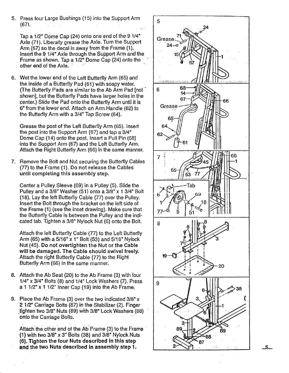
Press four Large Bushings (15) into the Support Arm
(671.
Tap a 1/2" Dome Cap (24) onto one end of the 9 1/4"
Axle (71). Liberally grease the Axle, Turn the Support
Arm(67) so the decal is away from the Frame (1):,
Insert the 9 1;_4"Axle through the Support Arm and the
Frame as Shown, Tap a 1/2" Dome Cap (24) onto the
other end of the Axle.
Wet the lower end of the Left Butterfly Arm (65) and
the inside of a Butterfly Pad (61) with soapy water.
(The Butterfly Pads are similar to the Ab Arm Pad [not "
shown], but the Butterfly Pads have larger holes in the
center.) Slide the Pad onto the Butterfly Arm until it is
6" from the lower end. Attach an Arm Handle (62) to
the Butterfly Arm with a 3/4" Tap Screw (64).
Grease the post of the Left Butterfly Arm (65). Insert
the post into the Support Arm (67) and tap a 3/4"
Dome Cap (14) onto the post. Insert a Pull Pin (68)
into the Support Arm (67) and the Left Butterfly Arm.
Attach the Right Butterfly Arm (66) in the same manner.
Remove the Bolt and Nut securing the Butterfly Cables
(77) to the Frame (1). Do not release the Cables
until completing this assembly step.
Center a pulley Sleeve (69) in a Pulley (5). Slide the
Pulley and a 3/8" Washer (51) onto a 3/8" x 1 3/4" Bolt
(18). Lay the left Butterfly Cable (77) over the Pulley.
Insert the Bolt through the bracket on the left side of
the Frame (1) (see the inset drawing). Make sure that
the Butterfly Cable is between the Pulley and the indi-
cated tab. "13ghten a 3/8" Nylock Nut (6) onto the Bolt.
Attach the left Butterfly Cable (77) to the Left Butterfly
Arm (65) with a 5/16" x 1" Bolt (53) and 5/16" Nylock
Nut (45). Do not overtighten the Nut or the Cable
will be damaged. The Cable should swivel freely.
Attach the right Butterfly Cable (77) to the Right
Butterfly Arm (66) in the same manner.
Attach the Ab Seat (20) to the Ab Frame (3) with four
1/4" x 3/4" Bolts (8) and 1/4" Lock Washers (7). Press
a I 1/2" x 1 1/2" Inner Cap (19) into the Ab Frame.
Place the Ab Frame (3) over the two indicated 3/8" x
2 1/2" Carriage Bolts (87) in theStabilizer (2). Finger
.tighten two 3/8" Nuts (89) with 3/8" Lock Washers (88)
onto the Carriage Bolts.
Attach the other end of the AI_ Frame (3) to the Frame
(1) with two 3/8" x 3" Bolts (38) and 3/8" Nylock Nuts
(6). Tighten the four Nuts described In this step
and the two Nuts described in assembly step 1.
5
24
|
9
-66
--1
3 " "' (
3 1
\
..5_-
Loading ...
Loading ...
Loading ...