
TOOLS NEEDED
• Adjustable wrench
• Phillips head screwdriver
• Brazing equipment
• Piping solder or flux
.4,CAUTION: Disconnect the electricalpower
supplg before installing.
Fll Placethe Heater the Vertical
Hydronic
onto
Zoneline by locating the four holes in its side
flanges over the four bolts on the top of the
Zoneline.
HL!dronic
heater
bolts
Zoneline
Locating
holes (_nd
bolts
F21 Attach Hydronic Heater to using
the the Zoneline
6 screws.
,
31-61420 I
07-07 JR
I
B] Connect the tubing.
There are two options: [] Standard Connection or
[] By-Pass Connection.
Choose the appropriate connection for your
installation requirements.
Standard Connection Option
Connect the 90° elbow to the upper outlet tube.
Connect the shut-off valve to the other end of the
90° elbow.
Shut-off
valve
90°
elbow
tube
FB1 By-Pass Connection Option
Connect the long two-bend tube to the lower inlet
tube, turn it and connect it to the T-fitting in the
outlet tube. Connect the shut-off valve to the other
end of the T-fitting.
Shut-off
valve
T-fitting
two-bend
tube
Lower inlet
tube
Printed in Chino
Installation Instructions
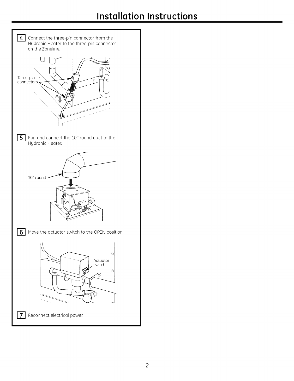
14"1 Connect the from the
three-pin
connector
Hgdronic Heater to the three-pin connector
on the Zoneline.
U
Three-pin _\
connectors
I-'S1 Runand the !0" round duct the
connect to
Hgdronic Heater.
10" round
r61 Move the actuator switch to the OPENposition.
Actuator
rT1 Reconnect electrical power.
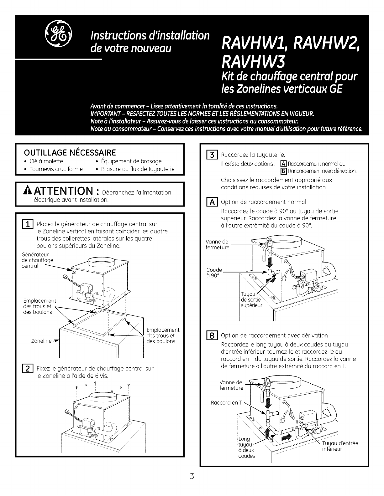
OUTILLAGE NECESSAIRE
• CI__ molette • Equipement de brasage
• Tourneviscruciforme • Brasureou flux de tugauterie
IkATTENTION :D branchez,'alimentation
_lectrique avant installation.
r_ Placez g_n_rateur chauffage sur
le de central
le Zoneline vertical en faisant colncider les quatre
trous des collerettes lat_rales sur lesquatre
boulons sup_rieurs du Zoneline.
G_n@roteur
de chQuffage
centrQI
Emplucement
des trous et
des boulons
Zoneline
Emplucement
des trous et
des boulons
F2-1 Fixez g_n_rateur chauffage sur
le de central
le Zoneline _ I'aide de 6 vis.
I
B] Raccordez la tugauterie.
IIexiste deuxoptions: [] Raccordementnormalou
[] Raccordementavecderivation.
¢hoisissez le raccordement appropri_ aux
conditions requises de votre installation.
Option de raccordement normal
Raccordez le coude _ 90° au tugau de sortie
sup_rieur. Raccordez la vanne de fermeture
I'autre extr_mit_ du coude _90°.
W]nne de
fermeture
Coude
90°
sup_rieur
Option de raccordement avec d_rivation
Raccordez le long tugau _ deux coudes au tugau
d'entr_e inf_rieur,tournez-le et raccordez-le au
raccord en Tdu tugau de sortie. Raccordez la vanne
de fermeture _ I'autre extr_mit_ du raccord enT.
Wnne de
fermeture
RQccorden T
0 deux
coudes
Tug(]u d'entr_e
inf_rieur
3
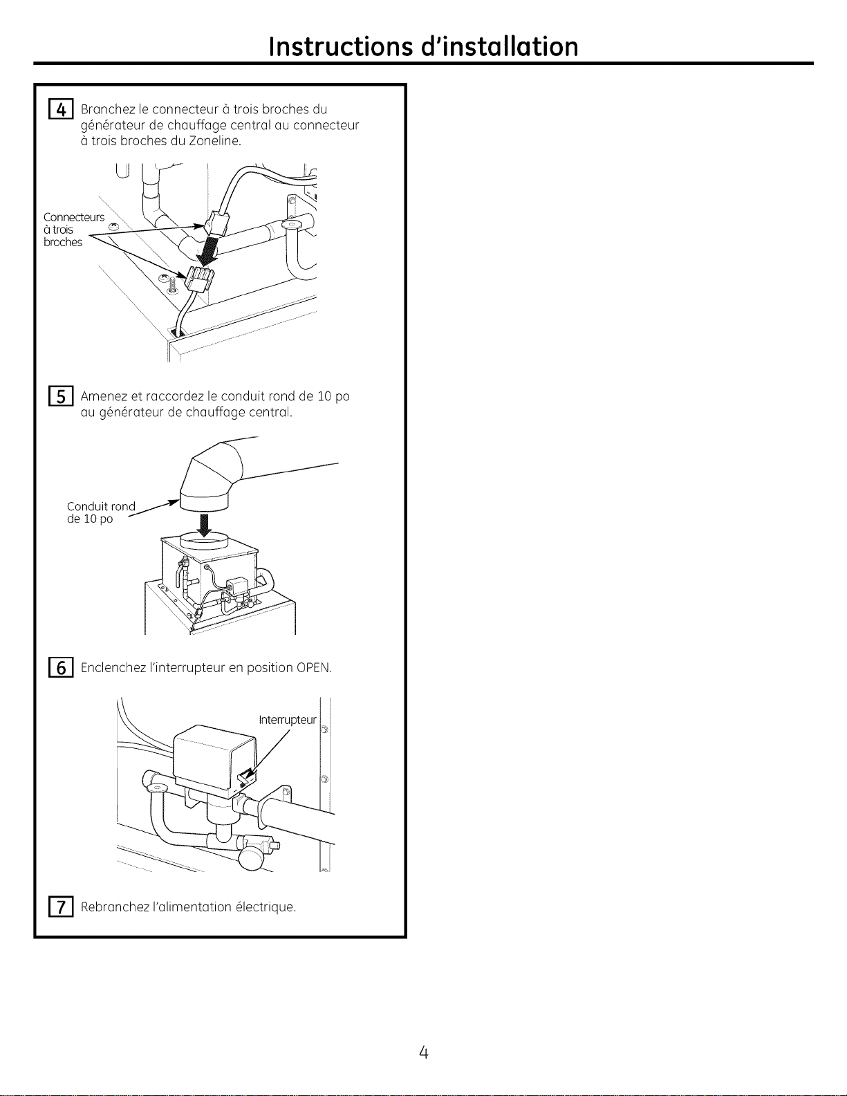
Instructions d'installation
14--I Branchez le (_trois broches du
connecteur
g_n_rateur de chauffage central au connecteur
trois broches du Zoneline.
U
Connecteurs \
_]trois © \
broches
r_ Amenez raccordez le conduit fond de
et 10
po
au g_n_rateur de chauffage central.
Conduit ron
de 10 po
r61Enclenchez I'interrupteur en position OPEN.
Interrupteur
r_l Rebranchez I'alimentation _lectrique.
4
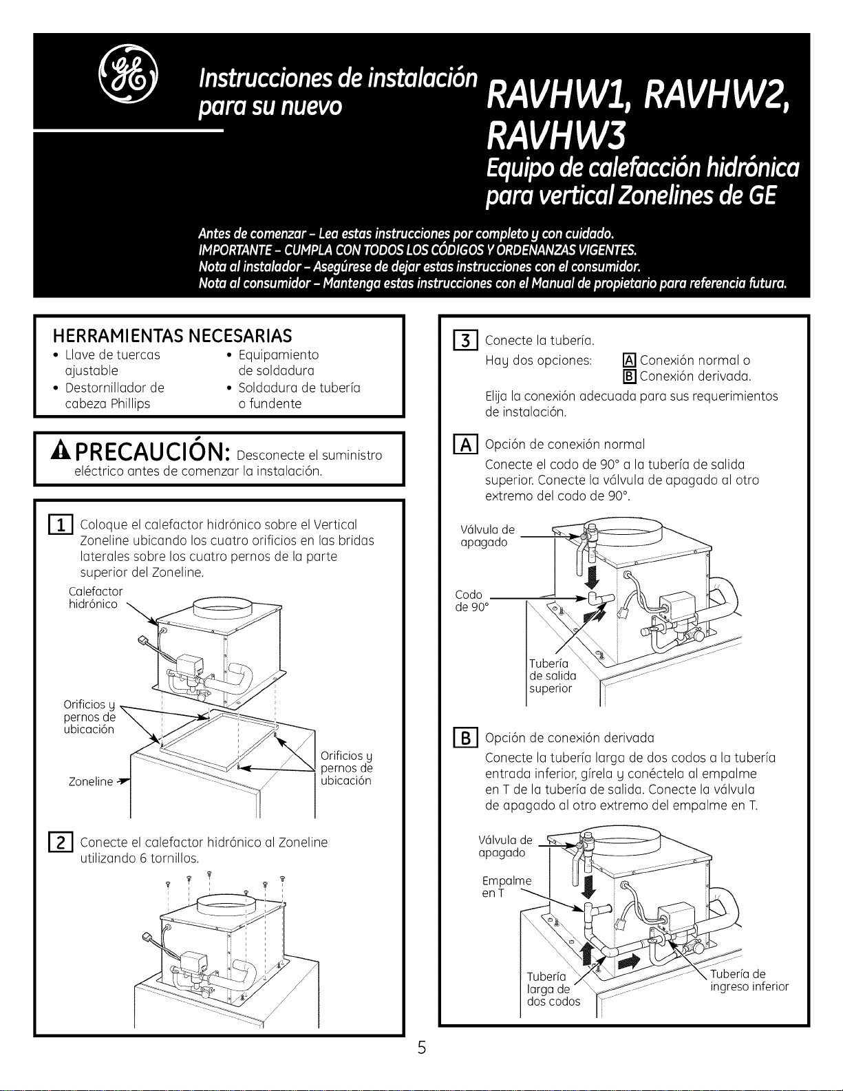
HERRAMIENTAS NECESARIAS
• Llove de tuercos • Equipomiento
ojustoble de soldoduro
• Destornillodor de • Soldoduro de tuberfo
cobezo Phillips o fundente
I " I
PRECAUCION: Desconecte elsuministro
el@ctricoantes de comenzor Io instoloci6n.
r_ Coloque el colefoctor hidr6nico sobre el Vertical
Zoneline ubicondo los cuotro orificios en los bridos
Ioteroles sobre los cuotro pernos de Io porte
superior del Zoneline.
Colefoctor
hidr6nico
Orificios y
pernos de
ubicuci6n
Zoneline
Orificios y
pernos de
ubicuci6n
F_l Conecte el colefoctor hidr6nico ol Zoneline
utilizondo rotornillos.
B]
Conecte Iotuberfo.
Hog dos opciones: [] Conexi6n normal o
[] Conexi6n derivodo.
EIUoIoconexi6n odecuodo poro sus requerimientos
de instoloci6n.
Opci6n de conexi6n normal
Conecte el codo de 90° o Iotuberfo de solido
superior. Conecte Io v61vulode opogodo ol otro
extremo del codo de 90°.
V61vulude
upugudo
Codo
de 90°
de sulidu
superior
r_ opci6n de conexi6n derivodo
Conecte Iotuberfo Iorgo de dos codos o Io tuberfo
entrodo inferior, gfrelo h con6ctelo ol empolme
en Tde Iotuberfo de solido. Conecte Io v61vulo
de opogodo ol otro extremo del empolme en T.
V61vulude
upugudo
Empolme
en T
larga de
dos codos
Tuberia de
ingreso inferior
Instrucciones de instalaci6n
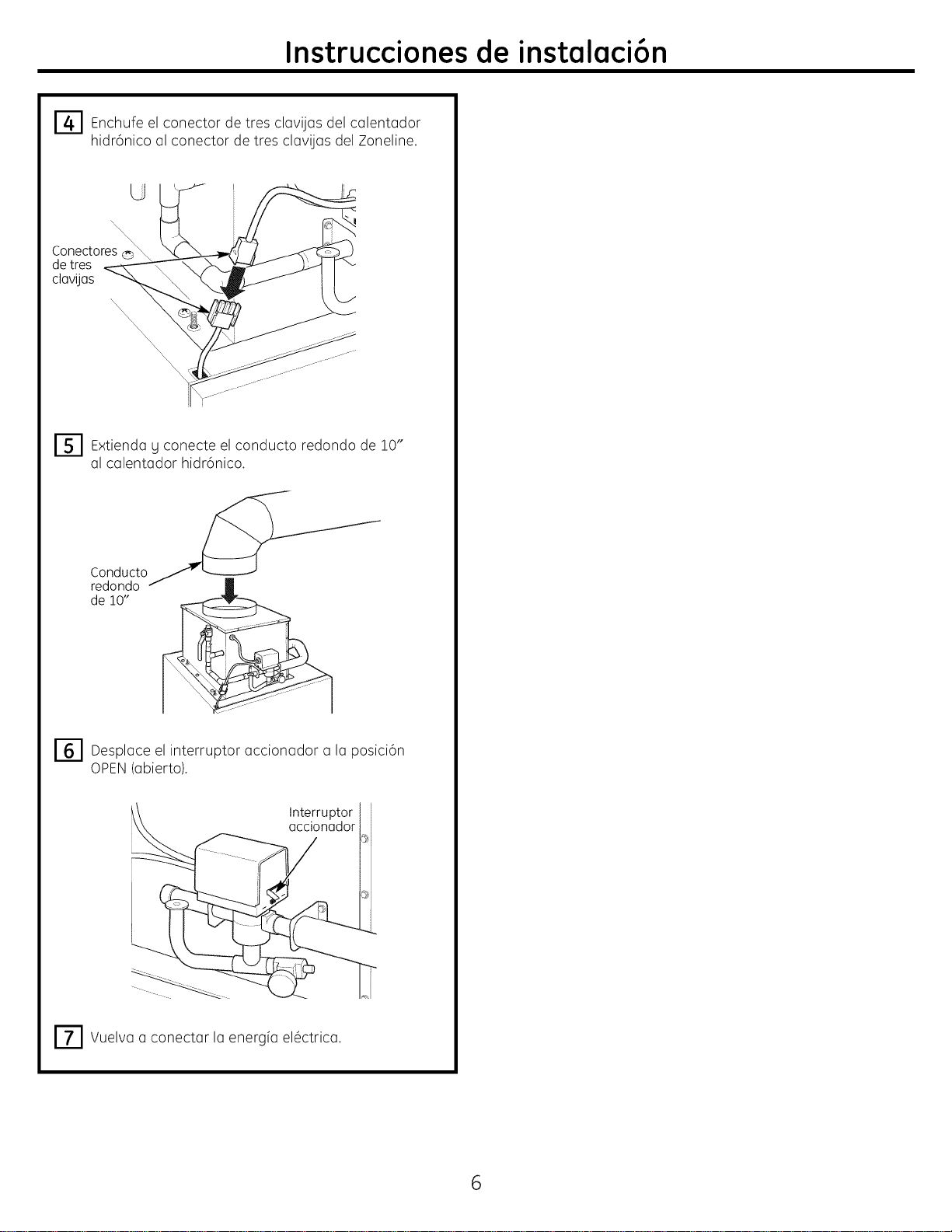
14"-I Enchufe el de del calentador
conector tres
clavijas
hidr6nico al conector de tres clavijas del Zoneline.
U
Conectores © \
detres
clavijas
r_ Extienda el conducto redondo de 10"g
conecte
al calentador hidrbnico.
Conducto_ ''I/
redondo f
de 10"
r_ Desplace interruptor a posici6n
el accionador la
OPEN(abierto).
Interruptor
accionador
r_ Vuelva a conectar IQenergfa el_ctrica.
6

Notas

Notas
8

