Loading ...
Loading ...
Loading ...
14
© 2021 United States Stove Company
GAS CONNECTION
1. We recommend using only new black iron or
steel pipe. CHECK LOCAL CODES.
2. The gas supply line shall be sized and installed
to provide a sufcient supply of gas to meet
the maximum demand of the heater without
undue loss of pressure.
3. The sealant used on the threaded joints of the
gas pipe must be a type resistant to the action
of L.P. Gas. (This sealant should be applied
lightly to main threads to ensure excess sealant
does not enter lines.)
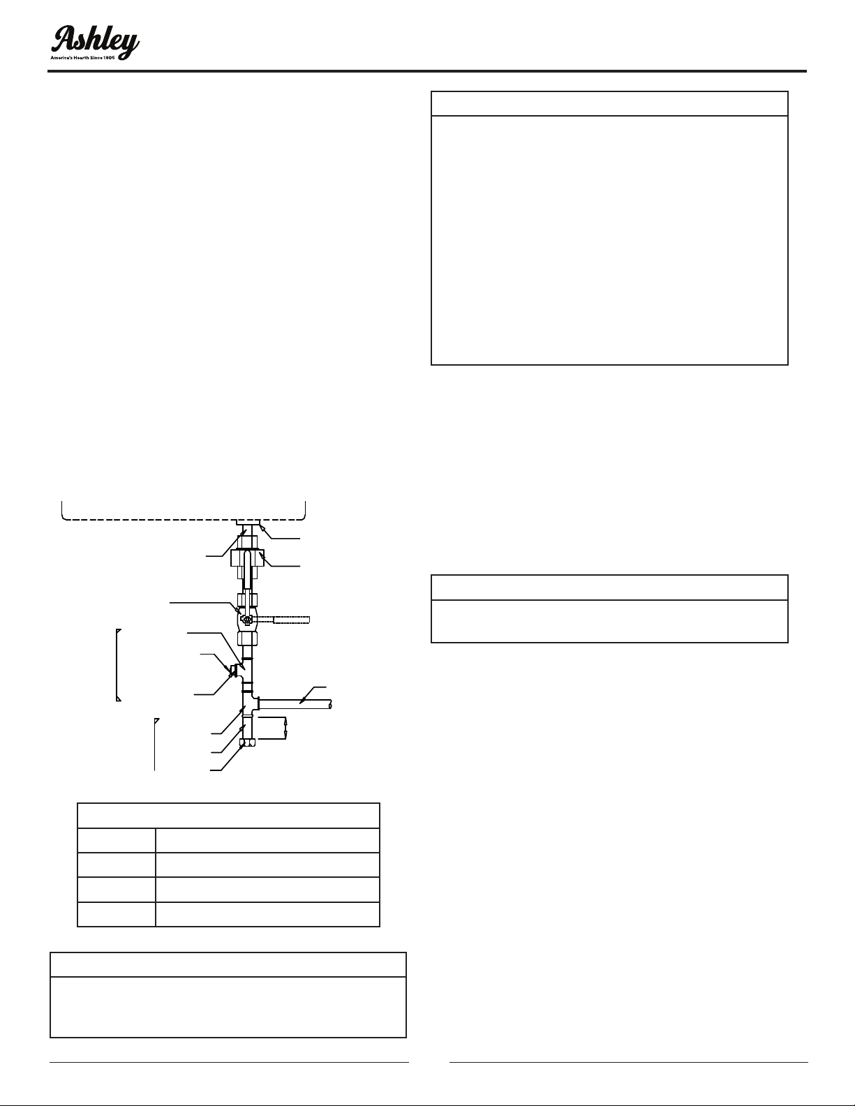
4. The supply system must include a manual
shut off valve and connection in the line, so the
heater can be disconnected for servicing. (See
Figure 18).
5. Include a drip leg (trap) and a plugged 1/8”
N.P.T. tapping in the line. The tapping should be
accessible for test gauge connections upstream
of the gas supply connection to the heater.
3/8” NPT PIPE NIPPLE
PIPE NIPPLE
1/8” NPT PLUG TAP
REDUCER BUSHING
TO 1/8” NPT
SEDIMENT
TRAP
TEST GAUGE
CONNECTION
TEE JOINT
TEE JOINT
CLOSED
OPEN
GROUND JOINT UNION
APPLIANCE GAS INLET
FROM GAS ME
TER
3 (76.2 MM)
MINIMUM
CAP
MANUAL SHUTOFF
VALVE
Figure 18
Pressure
Nat. Gas 7” W.C to 10.5” W.C.
Nat. Gas 178 mm W.C. to 267 mm W.C.
L.P. Gas 11” W.C. to 14” W.C.
L.P. Gas 280 mm W.C. to 356 mm W.C.
WARNING:
• FOR L.P. GAS, USE PRESSURE REGULATED
GAS SUPPLY. DO NOT DIRECTLY CONNECT
LP SUPPLY TANK TO THE PRESSURE
REGULATOR ON THE HEATER. THE LP SUPPLY
TANK MUST HAVE ITS OWN SEPARATE
PRESSURE REGULATOR THAT CAN REDUCE
THE SUPPLY TANK GAS PRESSURE DOWN
TO A MAXIMUM OF 14 INCHES (355 MM) OF
WATER COLUMN PRESSURE.
• ALL GAS PIPING AND CONNECTIONS
MUST BE TESTED FOR LEAKS AFTER
INSTALLATION OR SERVICING. ALL LEAKS
MUST BE CORRECTED IMMEDIATELY.
CHECK AFTER GAS CONNECTION
1. Make sure the control of the heater is in the
“OFF” position.
2. Open the manual shut off valve. Test for leaks by
applying liquid detergent to all joints. Check all
joints from gas meter to thermostat gas valve.
(Bubbles forming indicate a gas leak)
3. Correct any leak defect at once.
CAUTION:
NEVER USE AN OPEN FLAME TO CHECK FOR
LEAKS
PRESSURE TESTING SUPPLY LINE
ATTENTION: This appliance and its appliance main
gas valve must be disconnected from the gas
supply piping system during any pressure testing
of that system at test pressures in excess of 1/2 psi
(3,5 kPa). The appliance must be isolated from the
gas supply piping system by closing equipment
shutoff valve during any pressure testing of the gas
supply piping system at test pressures equal to or
less than 1/2 psi (3,5 kPa).
HIGH ALTITUDE INSTALLATIONS
This appliance may be installed at higher altitudes.
Please refer to National Fuel Gas Code ANSI Z223.1/
NFPA 54, CSA-B149.1 Natural Gas and Propane
Installation Code, local authorities, or codes
having jurisdiction in your area regarding derate
guidelines. Per the above referenced codes, for
elevations above 2,000 ft (610 m), input ratings are
to be reduced by 4% for each 1,000 ft (305 m).
INSTALLATION
IMPORTANT:
HOLD THE GAS INLET OF THE APPLIANCE
WITH WRENCH WHEN CONNECTING IT TO
GAS PIPING AND/OR FITTINGS.
Loading ...
Loading ...
Loading ...