Loading ...
Loading ...
Loading ...
12
© 2021 United States Stove Company
IMPORTANT:
THE VENT-AIR INTAKE SYSTEM MUST BE
PROPERLY INSTALLED TO ENSURE PROPER
AND SAFE OPERATION. THE VENT-AIR
INTAKE SYSTEM MUST ALSO BE PROPERLY
RE-INSTALLED AND RESEALED TO ENSURE
PROPER AND SAFE OPERATION.
WARNING:
FAILURE TO POSITION THE PARTS IN
ACCORDANCE WITH THESE DIAGRAMS OR
FAILURE TO USE ONLY PARTS SPECIFICALLY
APPROVED WITH THIS APPLIANCE MAY
RESULT IN PROPERTY DAMAGE OR PERSONAL
INJURY.
IMPORTANT:
THE APPLIANCE’S VENTING SYSTEM SHOULD
BE INSPECTED AT LEAST ONCE A YEAR AND
IMMEDIATELY CLEANED IF NECESSARY.
CAUTION:
ALL JOINTS MUST BE AIR-TIGHT.
CAUTION:
THE VENT PIPE MUST HAVE A SLIGHT
DOWNWARD SLOPE. 1/4” PER FOOT.
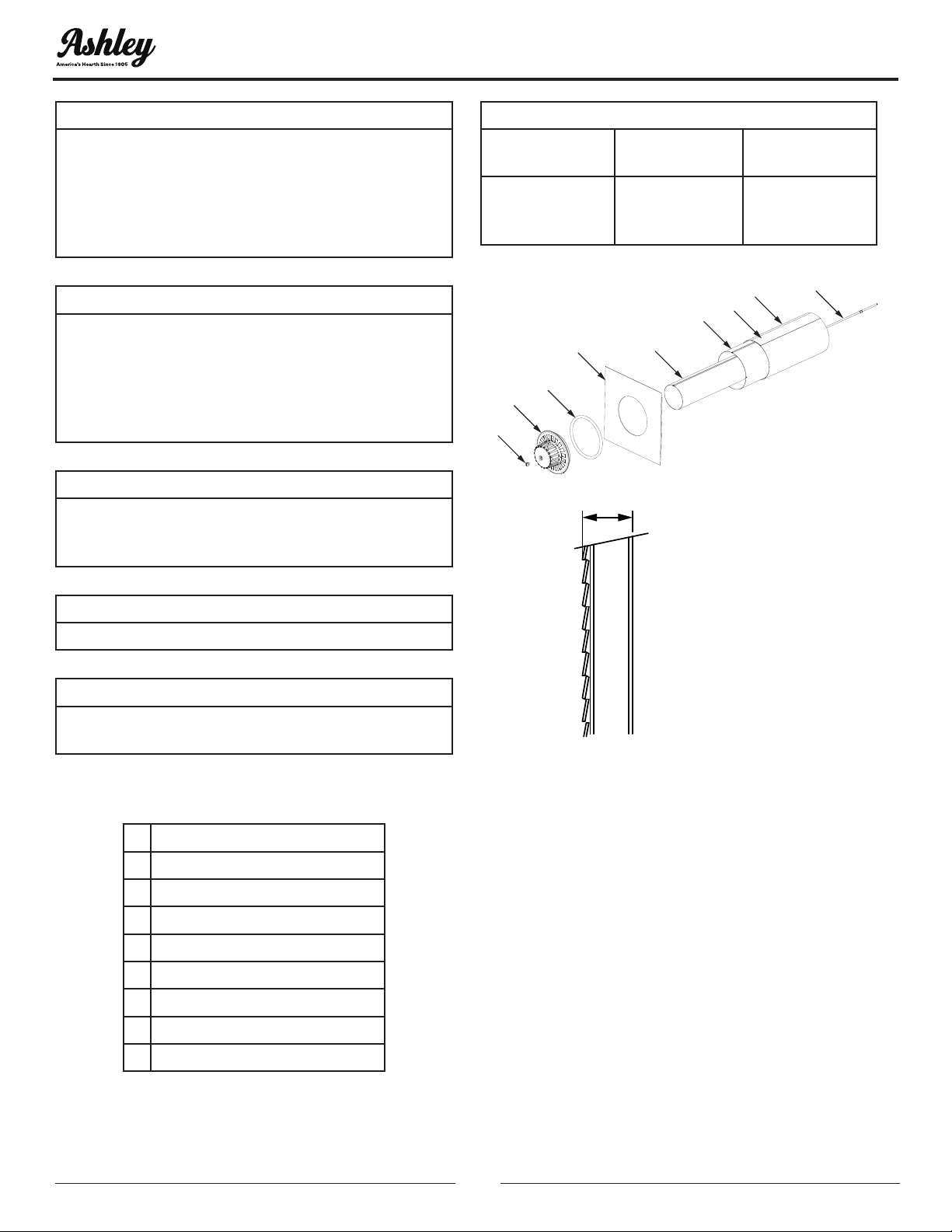
The venting system consists of:
A Vent Cap
B Vent Pipe
C Vent-Air Intake Pipe
D Rod
E Nut
F Outdoor Mounting Plate
G Silicon-Rubber Ring
H Tape
i Insulation
Table 3 Lengths Of Pipes And Rod.
Vent Pipe (B)
Vent-Air Intake
Pipe (C)
Rod (D)
Wall Thickness
+ 3-3/8“
(86 mm)
Wall Thickness
+ 2-1/2“
(64 mm)
Wall Thickness
+ 5-7/8“
(149.5 mm)
A
E
G
F
B
C
H
i
D
Figure 12
*
Minimum of
4-1/2” (115 mm)
Wall Thickness
Maximum of
10” (254 mm)
Wall Thickness
*
Figure 13
Measure thickness of the wall as shown in gure 13.
1. If any of the following are long trim them
according to thickness of the wall, (see table 3):
• (B) vent pipe
• (C) vent-air intake pipe
• (i) insulation
• (D) rod
2. The hole at the outside of the wall must be a
square of 11-1/4” (286 mm) X 11-1/4” (286 mm) (see
gure 14).
3. From the outside of the wall, screw the rod
(D) slightly onto support located inside the
appliance ue outlet.
4. Wrap the vent-air intake pipe (C) with the
provided insulation (i) (foil side out) and place
the provided strip of tape (H) down the seam to
secure it.
INSTALLATION
Loading ...
Loading ...
Loading ...