NUMBER 917.255460
MAN +
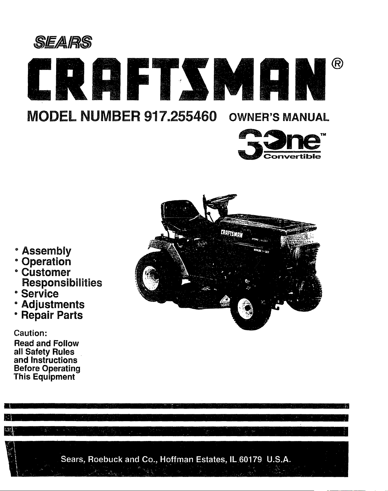
OWNER'S MANUAL
Convertible
+Assembly
° Operation
"Customer
Responsibilities
- Service
"Adjustments
° Repair Parts
Caution:
Read and Follow
all Safety Rules
and Instructions
Before Operating
This Equipment
liU ................ I'1111'"11'11 IIII/I IIII ' I II III " ""''"''' "'"
[] IllUlII IIIII'L I
CONGRATULATIONS on your purchase of a Sears
tractor. It has been designed, engineered and manufac-
tured to give you the best possible dependability and
performance°
Should you experience any problem you cannot easily
remedy, please contact your nearest Sears Service
CentedDepartmento We have competent, well-trained
technicians and the proper tools to service or repair this
unit.
Please read and retain this manual The instructions will
enable you to assemble and maintain your unit properly°
Always observe the "SAFETY RULES ..
MODEL
NUMBER 917255460
SERIAL
NUMBER
DATE OF PURCHASE
THE MODELAND SERIAL NUMBERSWlLLBE FOUND
ON A PLATE UNDER THE SEAT.
YOU SHOULD RECORD BOTH SERIAL NUMBER AND
DATE OF PURCHASE AND KEEP IN A SAFE PLACE
FOR FUTURE REFERENCE°
MAINTENANCE AGREEMENT
A Sears maintenance agreement is available on this prod-
ucto Contact your nearest Sears store for details,
CUSTOMER RESPONSIBILITIES
Q
O
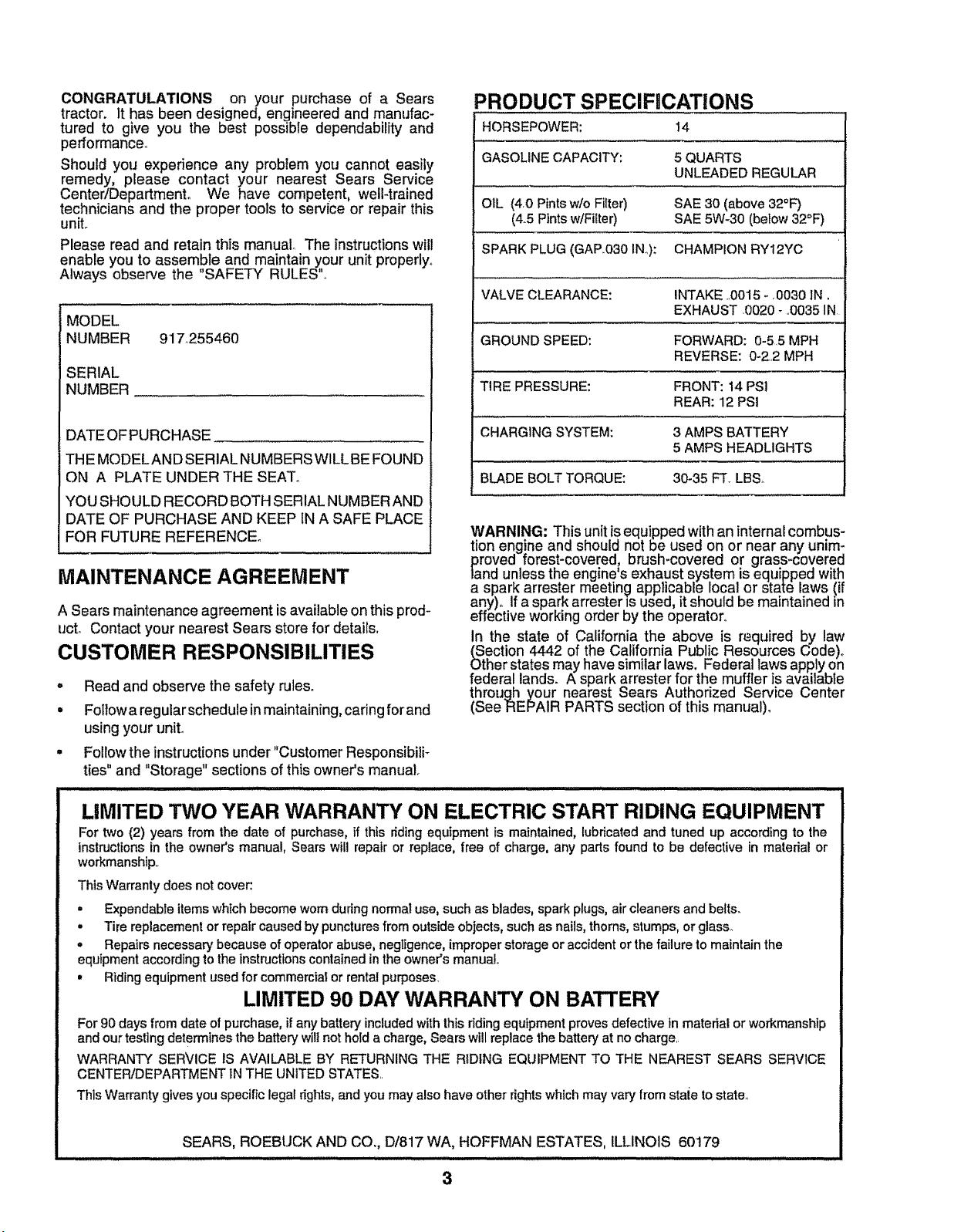
PRODUCT SPECIFICATIONS
HORSEPOWER: 14
GASOLINECAPACITY: 5 QUARTS
UNLEADEDREGULAR
OIL (4,0 Pintsw/o Filter) SAE 30 (above 32°F)
(4_5Pintsw/Filter) SAE 5W-30 (below32°F)
SPARK PLUG(GAP,.030IN..): CHAMPION RY12YC
VALVECLEARANCE: INTAKE ..0015- 0030 IN,
EXHAUST ,0020- ,.0035IN
GROUNDSPEED: FORWARD: 0-5.5 MPH
REVERSE: 0-2..2MPH
TIRE PRESSURE: FRONT: 14 PSI
REAR: 12 PSI
CHARGINGSYSTEM: 3 AMPS BATTERY
5 AMPS HEADLIGHTS
BLADE BOLTTORQUE: 30-35 FT, LBS_
Read and observe the safety rules°
Fotlow a regularschedule in maintaining, caring for and
using your unit,.
Follow the instructions under "Customer Responsibili T
ties" and "Storage" sections of this owner's manual.
WARNING: This unit is equipped with an internal combus-
tion engine and should not be used on or near any unim;
proved forest-covered; brush-covered or grass-coverea
land unless the engine s exhaust system is equipped with
a spark arrester meeting applicable local or state laws (if
any), If a spark arrester is used, it should be maintained in
effective working order by the operator°
in the state of California the above is required by law
(_Section4442 of the California Public Resources Code)°
Other states may have similar laws. Federal laws apply on
federal lands. A spark arrester for the muffler is available
through your nearest Sears Authorized Service Center
(See REPAIR PARTS section of this manual).
LIMITED TWO YEAR WARRANTY ON ELECTRIC START RIDING EQUIPMENT
Fortwo (2) yearsfrom the date of purchase,if this ridingequipmentis maintained,lubricatedand tunedup accordingto the
instructionsin the owner'smanual,Sears willrepairor replace,free of charge,any partsfound to be defectivein material or
workmanship,.
ThisWarrantydoesnotcover:
, Expendableitemswhichbecomewornduringnormaluse,suchas blades,spark pk,_gs,aircleanersand belts_
, Tirereplacementor repaircausedby puncturesfromoutsideobjects,such as nails, thorns,stumps, orglass_
,, Repairsnecessarybecauseofoperatorabuse, negligence,improperstorageoraccidentorthefailure to maintainthe
equipmentaccordingtothe Instructionscontainedintheowner'smanual,,
• Ridingequipmentusedfor commemiatorrentalpurposes,
LIMITED 90 DAY WARRANTY ON BATTERY
For90 daysfrom dateofpurchase,if any batteryincludedwiththisridingequipmentprovesdefectivetn materialorworkmanship
andourtestingdeterminesthe batterywill not holda charge,Searswill replacethebatteryat no charge..
WARRANTY SERVICE IS AVAILABLE BY RETURNINGTHE RIDING EQUIPMENTTO THE NEAREST SEARS SERVICE
CENTER/DEPARTMENTiN THE UNITEDSTATES..
ThisWarranty gives you specific legal rights,and you may also haveother rights which may vary from stale tostate,.
SEARS, ROEBLICK AND CO., D/817 WA, HOFFMAN ESTATES, ILLINOIS 60179
i i!uiul_ i llllllll .....................
3
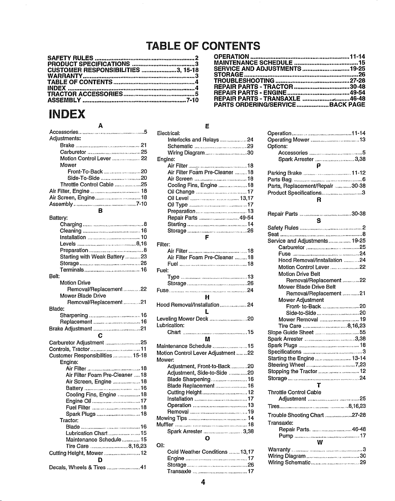
TABLE OF
SAFETY RULES ............................................................ 2
PRODUCT SPECIFICATIONS ...................................... 3
CUSTOMER RESPONSIBILITIES ..................... 3, 15-18
WARRANTY ................................................................... 3
TABLE OF CONTENTS ................................................. 4
INDEX ............................................................................ 4
TRACTOR ACCESSORIES ........................................... 5
ASSEMBLY .............................................................. 7-10
iNDEX
A
Accessories .......................................................5
Adjustments:
Brake .........................................................21
Carburetor ...........................................25
Motion Control Lever ...............................22
Mower
Front-To+Back ....................................20
Side-To+Side ...............................20
Throttle Control Cable ...................25
Air Filter, Engine ............................................18
Air Screen, Engine ..........................................18
Assembly ..........................................................7-10
B
Battery:
Charging ...............................................8
Cleaning ................................................16
Installation .......................................................10
Levels ...................................................8,16
Preparation .......................................................8
Starling with Weak Battery ...........23
Storage ................................................26
Terminals ............................................16
Belt:
Motion Drive
Removal/Replacement ................22
Mower Blade Drive
Removal/Replacement ..................21
Blade:
Sharpening ........................................16
Replacement ......................................t6
Brake Adjustment ......................................2t
C
Carburetor Adjustment ................................25
Controls, Tractor .................................... 11
Customer Responsibilities .............. 15+18
Engine:
Air Filter. ......................................18
Air Filter Foam Pre-Cleaner .....18
Air Screen, Engine .........................18
Battery .....................................................t6
Cooling Fins, Engine ...................18
Engine Oil .......................................t7
Fuel Filter .....................................18
Spark Plugs ................................18
Tractor:
Blade ......................................................16
Lubrication Chart ..............................t5
Maintenance Schedule ..............15
Tire Care ................................8,16,23
Cutting Height, Mower .............................t2
D
Decals, Wheels & Tires ..............................41
CONTENTS
OPERATION ........................................................... 11-14
MAINTENANCE SCHEDULE ...................................... 15
SERVICE AND ADJUSTMENTS ............................ 19-25
STORAGE .................................................................... 26
TROUBLESHOOTING ............................................ 27-28
REPAIR PARTS - TRACTOR ................................. 30+48
REPAIR PARTS - ENGINE ..................................... 49-54
REPAIR PARTS - TRANSAXLE ................. ._......... 46-48
PARTS ORDERING/SERVICE ................... BACK PAGE
E
Efectrieal:
Interlocks and Relays ............................24
Schematic ......................................................29
Wiring Diagram ........................................30
Engine:
Air Filter .................................................18
Air Filter Foam Pro+Cleaner ..............18
Air Screen ........................................t8
Cooling Fins, Engine ......................18
Ott Change .................................................17
Oil Level .............................................13,17
Oil Type .....................................................17
Preparation ........................................ 13
Repair Parts ............................... 49-54
Starting ................................................ 14
Storage ..................................................26
F
Filter:
Air Filter ................................................18
Air Filter Foam Pro-Cleaner ........ t8
Fuel .......................................................................18
Fuel:
Type .............................................................13
Storage
.....................................................
26
Fuse .................................................................................24
H
Hood Removal/lnstaflat+on..................... 24
L
Leveling Mower Deck .......................................20
Lubrication:
Chart .....................................................15
M
Maintenance Schedule
..................................
15
Motion Control Lever Adjustment ....... 22
Mower:+
Adjustment, Front+to-Back ................20
Adjustment, Side+to+Side ................20
Blade Sharpening ..................................16
Blade Replacement ...........................t6
Cutting Height .......................................12
Installation .............................................17
Operation .......................................... 13
Removal ....................................................i9
.Mowing Tips .......................................................14
Muffler ............................................................................18
Spark Arrestor .....................................3,38
O
Oil:
Cold Weather Conditions ............13, t 7
Engine .....................................................................17
Storage ...................................................................26
Transaxle ..............................................17
Operation ............................................ 11-14
Operating Mower ...........................................13
Options:
Accessories .................................................5
Spark Arrester. ....................................3,38
P
Parking Brake ........................................11+12
Parts Bag ...............................................................6
Parts, Replacement/Repalr ..............30-38
Product Specifications......................................3
R
Repair Parts ....................................... 30+38
S
Safety Rules ...................................................2
Seat ........................................................ 8
Service and Adjustments ................ 19-25
Carburetor. ..........................................25
Fuse ..............................................................24
Hood Removal/Installation ................24
Motion Control Lever ..........................22
Motion Ddve Belt
Removal/Replacement ...................22
Mower Blade Drive Belt
Removal/Replacement .................21
Mower Adjustment
Front- to+Back .......................... 20
Side+to-Side ................................ 20
Mower Removal ................................ 19
Tire Care .................................. 8,16,23
S}ope Guide Sheet .................................. 55
Spark Arrester
......................................................
3,38
Spark Plugs .......................................................18
Specifications ........................................... 3
Starting the Engine ........................... 13-14
Steering Wheel .........................................7,23
Stopping the Tractor ..................................t2
Storage ...........................................................24
T
Throttle Control Cable
Adjustment ...................................... 25
_mS
.....................................................................
8,16,23
Trouble Shooting Chart .................. 27-28
Transaxle:
Repair Parts ......................................46-48
Pump ......................................................17
W
War+anty
...................................................................
3
Wiring Diagram ..................................................30
Wiring Schematic .........................................29
4
I,IIIL II III I IIll II I ...............................................................................................
ACC ES AND ATTACH
These accessories and attachments were available when the unit was purchased. They are also available at most Sears retail outlets,
catalog and service centers.. Most Sears stores can order these items for you when you provide the model number of your tractor.
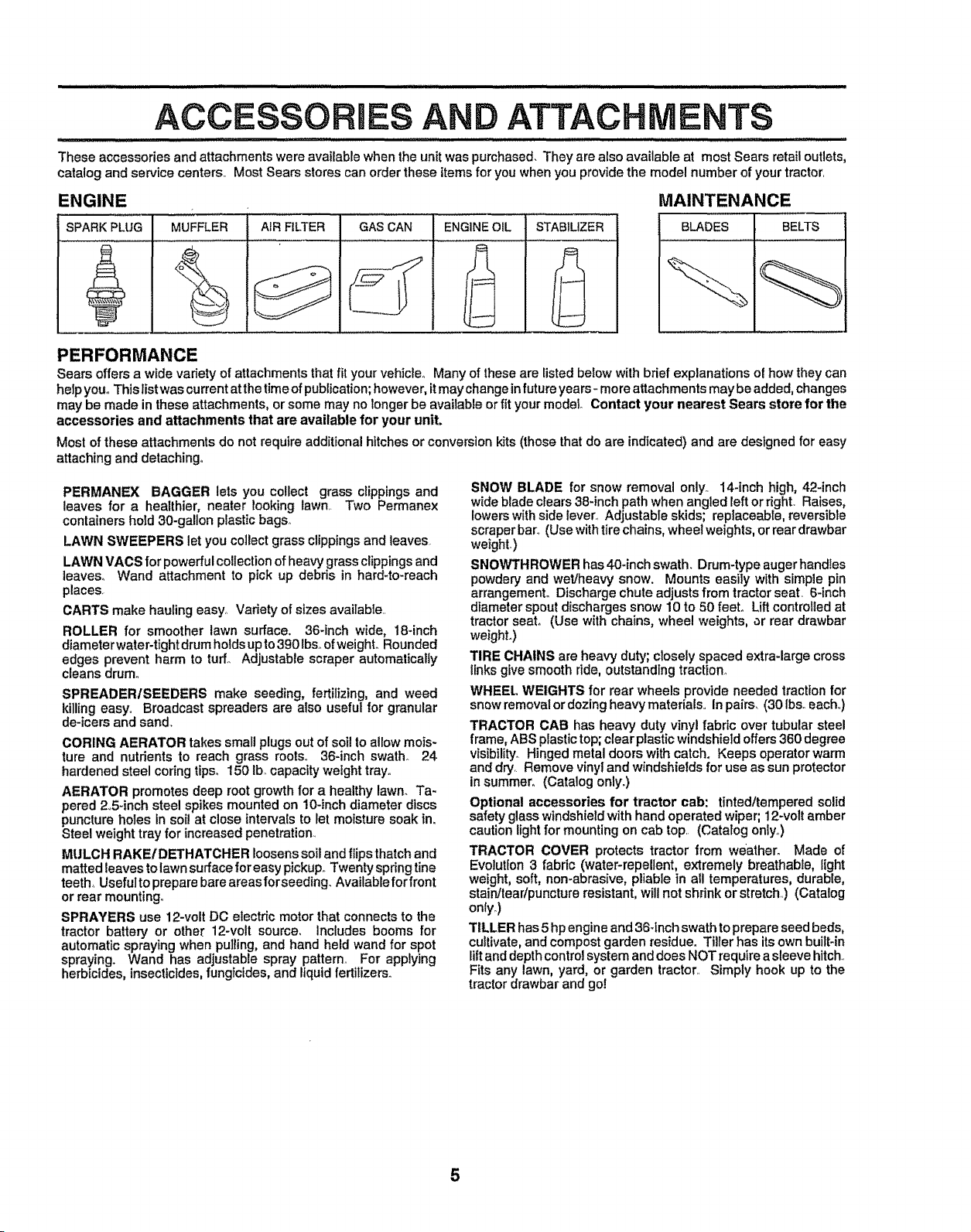
ENGINE
SPARK PLUG MUFFLER AIR FILTER GAS CAN ENGINEOIL STABILIZER
MAINTENANCE
BLADES BELTS
PERFORMANCE
Sears offers a wide variety of attachments that fit your vehicle.. Many of these are listed below with brief explanations of how they can
help you° This list was current at thetime ofpublication;however, it may change infuture years _moreattachments may be added, changes
may be made in these attachments, or some may no longer be available or fit your model Contact your nearest Sears store for the
accessories and attachments that are available for your unit.
Most of these attachments do not require additional hitches or conversion kits (thosethat do are indicated) and are designed for easy
attaching and detaching°
PERMANEX BAGGER lets you collect grass clippings and
leaves for a healthier, nearer looking lawn._ Two Permanex
containers hold 30-gallon plastic bags°
LAWN SWEEPERS let you collect grass clippings and leaves
LAWN VACS for powerfulcollectionof heavy grass clippingsand
leaves° Wand attachment to pick up debris in hard-to-reach
places.
CARTS make hauling easy. Variety of sizes avaiIable
ROLLER for smoother lawn surface. 36-inch wide, 18-inch
diameter water-tight drum holdsupto390 Ibs..ofweighL Rounded
edges prevent harm to turf° Adjustable scraper automatically
cleans drum°
SPREADER/SEEDERS make seeding, fertilizing, and weed
killing easy. Broadcast spreaders are also useful for granular
de-icers and sand.
CORING AERATOR takes small plugs out of soil to allow mois-
ture and nutrients to reach grass roots° 36-inch swath_ 24
hardened steel coring tips° 150 lb,.capacity wetght tray°
AERATOR promotes deep root growth for a healthy lawn. Ta-
pered 25-inch steel spikes mounted on 10-inch diameter discs
puncture holes in soil at close intervals to let moisture soak in,
Steel weight tray for increased penetration_
MULCH RAKE/DETHATCHER loosens soil and flips thatchand
matted leaves to lawn surface for easy pickup,.Twenty spring tine
teeth, Usefulto prepare bare areasforseedlng. Available for front
or rear mounting.
SPRAYERS use 12-volt DC electric motor that connects to the
tractor batten./ or other 12-volt source, Includes booms for
automatic spraying when pulling, and hand held wand for spot
spraying. Wand has adjustable spray pattern° For applying
herbicides, insecticides, fungFcides,and liquidfertilizers°
SNOW BLADE for snow removal only_ 14-inch high, 42-inch
wide blade clears 38-inch path when angled left or right. Raises,
lowers with side lever., Adjustable skids; replaceable, reversibte
scraper bar.. (Use withtire chains, wheel weights, or rear drawbar
weight.)
SNOV'urI"HROWERhas 40-inch swath. Drum-type augerhandles
powdery and wet/heavy snow. Mounts easily with simple pin
arrangemenL Discharge chute adjusts from tractor seat. 6*inch
diameter spout discharges snow 10 to 50 feet° Liftcontrolled at
tractor seat. (Use with chains, wheel weights, or rear drawbar
weighL)
TIRE CHAINS are heavy duty; closely spaced extra-large cross
links give smooth ride, outstanding traction..
WHEEL WEIGHTS for rear wheels provide needed traction for
snow removal or dozing heavy materials.. In pairs. (30 Ibsoeach..)
TRACTOR CAB has heavy duty vinyl fabric over tubular steel
frame, ABS plastic top; clear plastic windshield offers 360 degree
visibility. Hinged metal doors with catch. Keeps operator warm
and dry. Remove vinyl and windshields for use as sun protector
in summer. (Catalog only.)
Optional accessories for tractor cab: tinted/tempered solid
safety glass windshield with hand operated wiper; 12wolt amber
caution light for mounting on cab top.. (Catalog only.)
TRACTOR COVER protects tractor from weather. Made of
Evolution 3 fabric (water-repellent, extremely breathable, light
weight, soft, non-abrasive, pliable in all temperatures, durable,
stain/tear/puncture resistant, will not shrink or stretch..) (Catalog
only_)
TILLER has 5 hp engine and 36-inch swath to prepare seed beds,
cultivate, and compost garden residue, Tiller has itsown built-in
lift and depth control system and does NOT require a sleeve hitch..
Fits any lawn, yard, or garden tractor.. Simply hook up to the
tractor drawbar and go!
5
.................. iiiiilulll
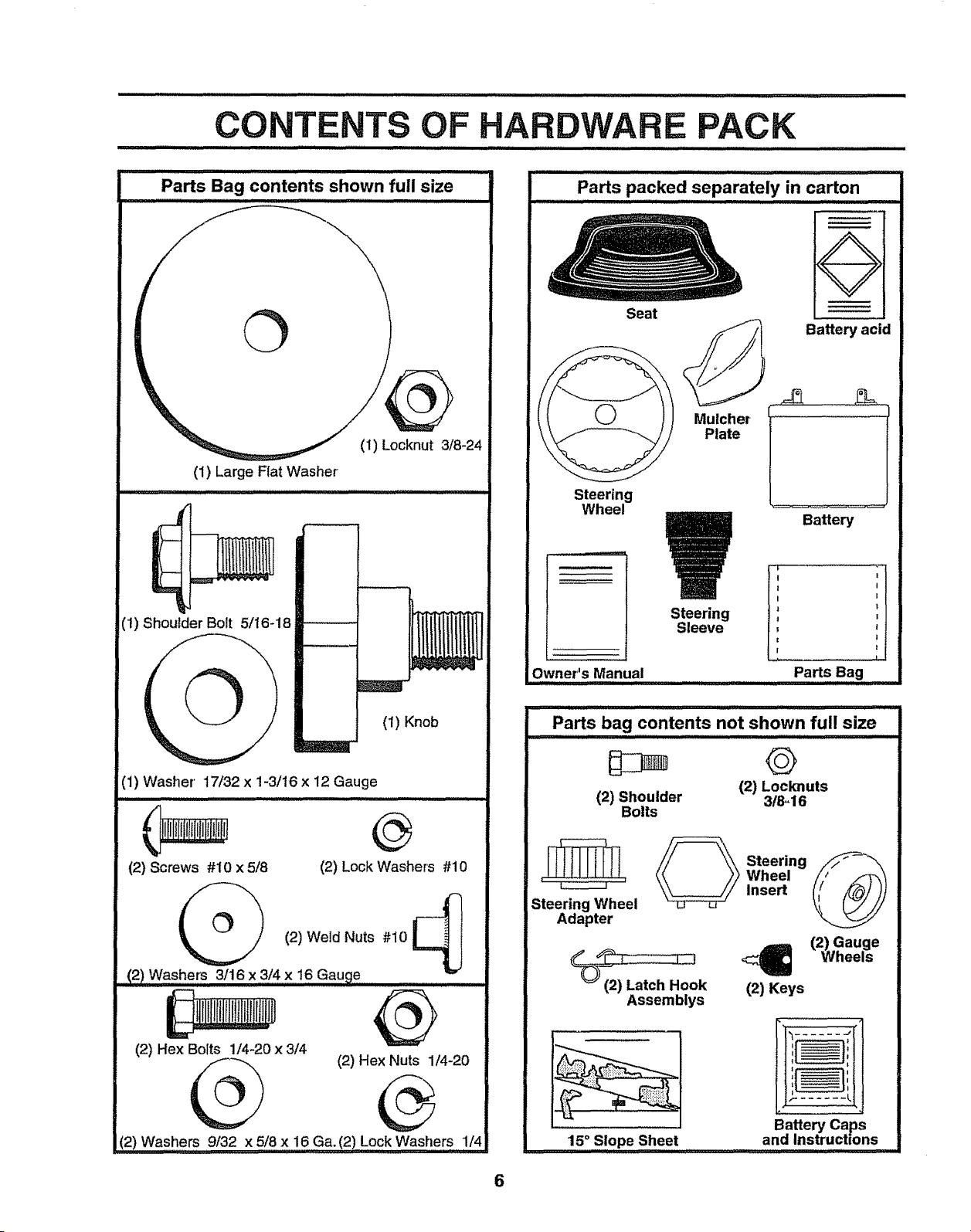
Parts Bag contents shown full size
(1) Locknut 3/8-24
(1) Large Flat Washer
........... ii
(1) Shoulder Bolt 5/16-18
(1) Knob
(1) Washer' 17/32 x 1-3/16 x 12 Gauge
(2) Screws #10 x 5/8
@
(2) Lock Washers #10
(2) Weld Nuts #10
(2) Washers 3/16 x 3/4 x 16 Gauge........
(2) Hex Bolts 1N-20 x 3/4
Q
(2) Washers 9/32 x 5/8 x 16 Ga.(2) Lock Washers 1/4
(2) Hex Nuts 1/4-20
Parts packed separately in carton
.... ...,,,,,,. i IlLii
Seat
Mulcher
Plate
Steering
Sleeve
O
Battery acid
Steering
Wheel
Owner's Manual
Battery
t
Parts Bag
Parts bag contents not shown full size
©
121Locknuts
(2) Shoulder 3/8,,16
Bolts
Steering Wheel
Adapter
_ teering
Wheel
Insert
(2) Gauge
<:_ Wheels
(2) Keys
Assemblys
15,°.Slope Sheet
Battery caps
and Instructtons
6
BLY
Your new tractor has been assembled at the factory with exception of those parts left unassembled for shipping purposes,
To ensure safe and proper operation of your tractor, all parts and hardware you assemble must be tightened securely. Use
the correct tools as necessary to insure proper tightness.
TOOLS REQUIRED FOR ASSEMBLY
A socket wrench set will make assembly easier° Standard
wrench sizes are listed.
(1) 9/16" wrench (2) 7/16" wrench
Phillips Screwdriver (1) 3/4" socket w/drive
Utility knife ratchet
Tire pressure gauge (1) 1/2" wrench
When right and left hand is mentioned in this manual, it
means when you are in the operating position (seated
behind the steering wheel).
TO REMOVE UNIT FROM CARTON
UNPACK CARTON
* Remove all accessible loose parts and parts cartons
from carton (See page 6),
, Cut along lines on carton, from top to bottom, all four
corners of carton and lay panels flato
, Check for any additional loose parts or cartons and
remove.
BEFORE ROLLING UNIT OFF SKID
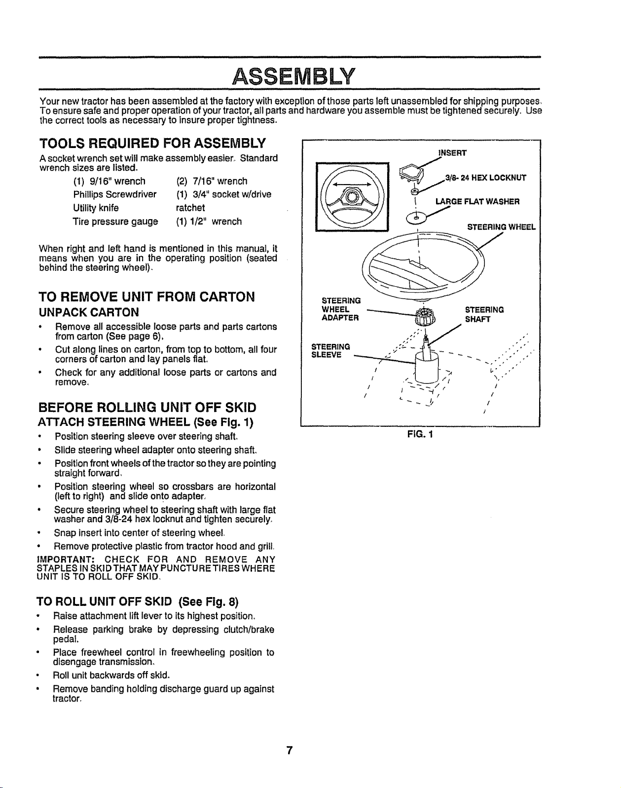
ATTACH STEERING WHEEL (See Fig. 1)
° Position steering sleeve over steering shaft.
• Slide steeringwheel adapter onto steering shaft
• Positionfrontwheels of the tractorso they are pointing
straightforward
• Position steering wheel so crossbars are horizontal
(left to right) and slide on!o adapter
• Secure steering wheel to steering shaft with large fiat
washer and 3/8-24 hex locknut and tighten securely
• Snap insert intocenter of steering wheel
• Remove protective plastic from tractor hood and grill
IMPORTANT; CHECK FOR AND REMOVE ANY
STAPLES INSKIDTHAT MAYPUNCTU RE TIRES WHERE
UNIT IS TO ROLL OFF SKID
INSERT
3/8- 24 HE)( LOCKNUT
LARGE FLAT WASHER
STEERING WHEEL
STEERING
WHEEL
ADAPTER
STEERING
SLEEVE
STEERING
SHAFT
FIG. I
TO ROLL UNIT OFF SKID (See Fig. 8)
• Raise attachment liftlever to its highest position,
• Release parking brake by depressing clutch/brake
pedal.
• Place freewheel control in freewheeling position to
disengage transmission.
• Roll unit backwards off skid.
• Remove banding holding discharge guard up against
tractor.
7
LY
HOW TO SET UP YOUR TRACTOR
PREPARE BATTERY (See Fig. 2)
H i, ii........................... illllllll i i
CAUTION: Wear eye and face shield.
Wash hands or clothing immediately if
accidentally in contact with batteryacid.
Do not smoke. Fumes from charged
battery acid are explosive.
Read the instructions included with the
battery vent caps. Always wear gloves,
clothing and goggles to protect your
hands, skin and eyes.
llllllllli i ....................
Your unit has a battery charging system which is sufficient
for normal use. However', pedodic charging of the battery
with an automotive charger will extend its life.
• See instructions packed with vent caps in parts bag.
o Fill battery with acid. Fill each cell until it reaches the
bottom of the vent wells. Do not overfi&
• Allow battery to stand and settle for at least thirty
minutes. After standing, check the level of acid. If
below the vent wells, add more acid until the correct
level is reached.
While battery is standing (after adding acid) and later, while
battery is being charged, continue with assembly of unit,
IMPORTANT; TO MAXIMIZE THE LIFE OF YOUR
BATTERY, IT tS NECESSARY THAT THE BATTERY BE
CHARGED BEFORE USE_ FAILURE TO CHARGE
BATTERY CAN RESULT IN A SHORTENED BATTERY
LIFEo
° Charge battery at a rate of 6 amperes for I hour, Use
a 12volt battery charger_Observe all safety precautions
required for battery charging°
o Check the acid level after' the battery is charged. If the
acid has fallen below the correct level, add distilled or
ironfree water.
• install the vent caps to cover the vent wellsoWash the
top of the battery with water to remove any acid, then
wipe dry,.
° Check battery case for leakage to make sure that no
damage has occurred in handling.
° Dispose of excess battery acid,, Neutralize acid for'
disposal by adding it to four inches of water' in a five
gallon plastic container. Stir with a wooden or plastic
paddle while adding baking soda until the addition of
more soda causes no more foaming,.
• Follow instructions on how to install battery.
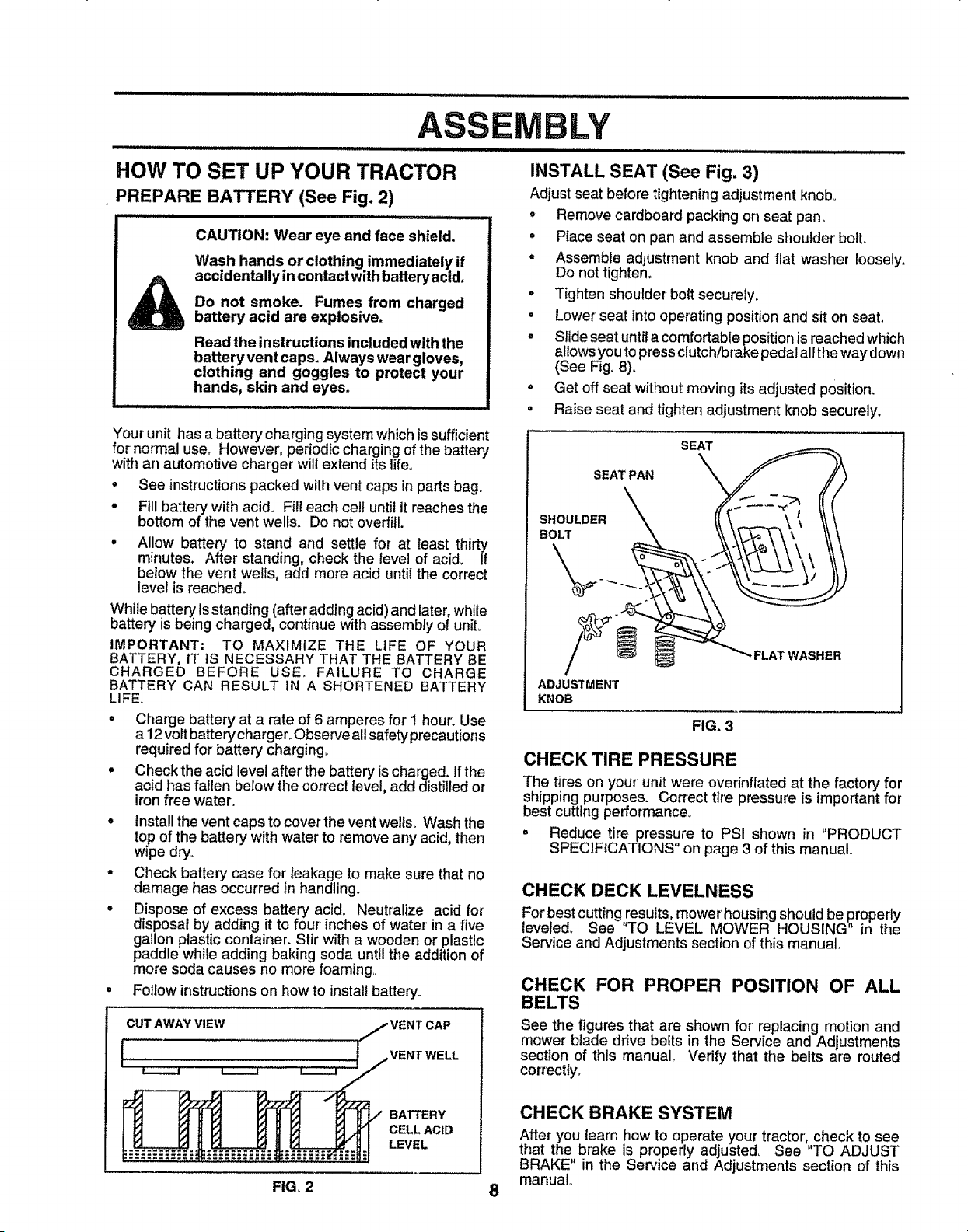
CUT AWAY VIEW
[
BATTERY
CELL ACID
LEVEL
INSTALL SEAT (See Fig. 3)
Adjust seat before tightening adjustment knob_
• Remove cardboard packing on seat pan,
° Place seat on pan and assemble shoulder bolt.
o Assemble adjustment knob and flat washer loosely.
Do not tighten.
= Tighten shoulder bolt securely.
° Lower seat into operating position and sit on seat.
° Slide seat until a comfortable position is reached which
allows you to press clutch/brake pedal alFthe way down
(See Fig. 8).
° Get off seat without moving its adjusted position.
° Raise seat and tighten adjustment knob securely.
SEAT
SEAT PAN
SHOULDER
BOLT
FLAT WASHER
ADJUSTMENT
KNOB
FIG. 3
CHECK TIRE PRESSURE
The tires on your unit were overinfiated at the factory for
shipping purposes. Correct tire pressure is important for
best cutting performance.
= Reduce tire pressure to PSI shown in "PRODUCT
SPECIFICATIONS on page 3 of this manual°
CHECK DECK LEVELNESS
For best cutting,results, mower housingshould be properly
leveled. See TO LEVEL MOWER HOUSING" in the
Service and Adjustments section of this manual.
CHECK FOR PROPER POSITION OF ALL
BELTS
See the figures that are shown for replacing motion and
mower blade drive belts in the Service and Adjustments
section of this manual, Verify that the belts are routed
correctly.
CHECK BRAKE SYSTEM
After you learn how to operate your tractor, check to see
that the brake is properly adjusted° See TO ADJUST
BRAKE" in the Service and Adjustments section of this
manual.
FIG, 2 8
,i, , ,u,,J,l,,,,,J1,/,,/i i
LY
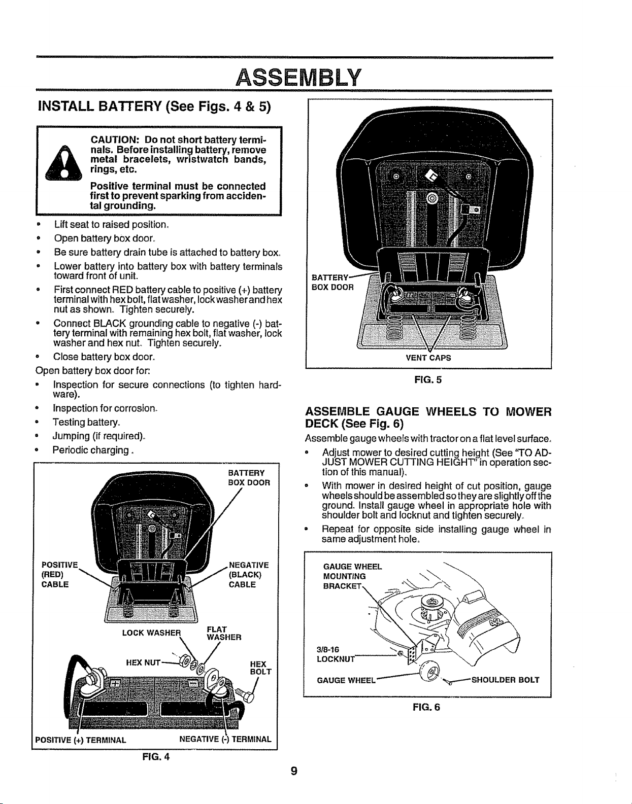
INSTALL BATTERY (See Figs. 4 & 5)
,lll,ll,lli,l,l,,llll i i ill i i i i
CAUTION: Do not short battery termi-
nals. Before installing battery, remove
metal bracelets, wristwatch bands,
rings, etc.
Positive terminal must be connected
first to prevent sparking from acciden-
tal grounding.
. Liftseat to raised position_
• Open battery box door,,
° Be sure battery drain tube is attached to battery box,,
° Lower battery into battery box with battery terminals
toward front of unit.
o First connect RED battery cable to positive (+) battery
terminal with hex bolt, fiat washer, Iockwasher and hex
nut as shown., Tighten securely.
- Connect BLACK grounding cable to negative (-) bat-
tery terminal with remaining hex bolt, flat washer, lock
washer and hex nut° Tighten securely.
° Close battery box door.
Open battery box door for:
° Inspection for secure connections (to tighten hard-
ware).
° Inspection forcorrosion_
° Testing battery,,
• Jumping (if required).
° Periodic charging°
BATTERY
BOX DOOR
POSITIVE NEGATIVE
(RED) (BLACK)
CABLE CABLE
LOCK WASHER FLAT
WASHER
HEX HEX
BOLT
POSITIVE (+) TERMINAL
NEGATIVE _TERMINAL
FIG. 4
BOX DOOR
VENT CAPS
FIG. 5
ASSEMBLE GAUGE WHEELS TO MOWER
DECK (See Fig. 6)
Assemble gauge wheels with tractor on a flat level surface°
= Adjust mower to desired cutting height (See "TO AD-
JUST MOWER CUTTING HEIGHT' in operation sec-
tion of this manual).
- With mower in desired height of cut position, gauge
wheels should be assembled so they are slightly off the
ground° Install gauge wheel in appropriate hole with
shoulder bolt and locknut and tighten securely°
• Repeat for opposite side installing gauge wheel in
same adjustment hole.
GAUGE WHEEL
MOUNTING
BRACKET,
GAUGE WHEEL BOLT
FIG. 6
9
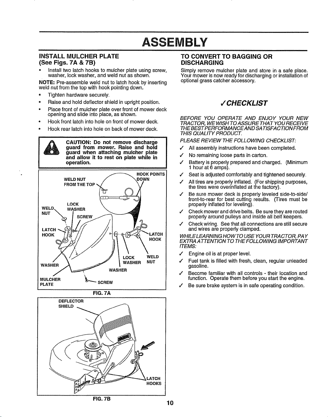
INSTALL MULCHER PLATE
(See Figs. 7A & 7B)
• Install two latch hooks to mutcher plate using screw,
washer, lock washer, and weld nut as shown°
NOTE" Pre-assemble weld nut to latch hook by inserting
wetd nut from the top with hook pointingdown.
= Tighten hardware securely_
= Raise and hold deflector shield in upright position°
, Place front of mulcher plate over front of mower deck
opening and slide into place, as shown.
• Hook front latch into hole on front of mower deck.
° Hook rear latch into hole on back of mower deck..
CAUTION: Do not remove discharge
guard from mower. Raise and hold
guard when attaching mulcher plate
and allow it to rest on plate while in
operation.
WELD NUT
FROM THE TOP
r
HOOK POINTS
DOWN
LOCK
WELD. WASHER
NUT ""X_ SCREW
LATCH
HOOK
HOOK
WASHER
LOCK WELD
i WASHER NUT
WASHER
MULCHER
PLATE
DEFLECTOR
SHIELD
FIG. 7A
MBLY
TO CONVERT TO BAGGING OR
DISCHARGING
Simply remove mulcher plate and store in a safe place.
Your mower' is now ready for discharging or' installation of
optional grass catcher accessory.
,/CHECKLIST
BEFORE YOU OPERATE AND ENJOY YOUR NEW
TRACTOR, WE WISH TO ASSURE THAT YOU RECEIVE
THE BEST PERFORMANCEAND SA TISFACTION FROM
THIS QUALI7¥ PRODUCT.
PLEASE REVIEW THE FOLLOWING CHECKLIST:
,I All assembly instructions have been completed.
,/ No remaining loose parts in carton°
,," Battery is properly prepared and charged. (Minimum
1 hour at 6 amps).
,/ Seat is adjusted comfortably and tightened securely.
,/" All tires are properly inflated. (For shipping purposes,
the tires were ovednflated at the factory)°
#" Be sure mower deck is properly leveled side-to-side/
front-to-rear for best cutting results° (Tires must be
properly inflated for' leveling).
,/ Check mower' and drive belts. Be sure they are routed
properly around pulleys and inside all belt keepers.
,I Check wiring. See that all connections are still secure
and wires are properly clamped.
WHILE LEARNING HOW TO USE YOUR TRACTOR, PAY
EXTRA A TTENTION TO THE FOLLOWING IMPORTANT
ITEMS:
,I Engine oil is at proper level.
#" Fuel tank is filled with fresh, clean, regular'unleaded
gasotine_
v" Become familiar with all controls - their location and
function. Operate them before you start the engine..
v" Be sure brake system is in safe operating condition.
_.LATCH
HOOKS
FIG. 7B
10
iil,lJll i ,,II,H Illlll
OPERATmON
i,l,l,l,,ll,,N,l,,,,,,,,,,l,,,l,,ill, ullu,//l,/,,,l,l,l,,ll,i ill ii
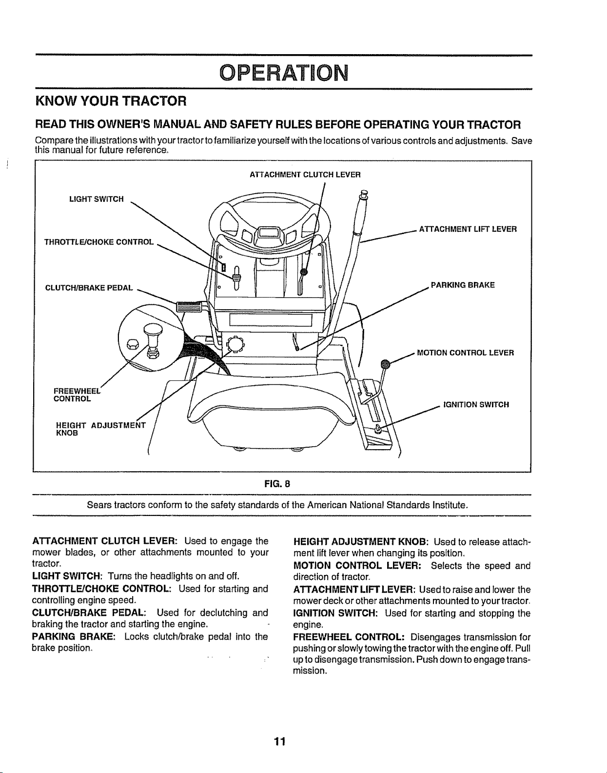
KNOW YOUR TRACTOR
READ THIS OWNER'S MANUAL AND SAFETY RULES BEFORE OPERATING YOUR TRACTOR
Compare the illustrationswithyourtractortofamiliarize yourselfwiththe locationsofvariouscontrolsand adjustments° Save
this manual for future reference°
ATTACHMENT CLUTCH LEVER
LIGHT SWITCH
THROTTL_CHOKECONTROL
LIFT LEVER
CLUTCH/BRAKE PEDAL
PARKING BRAKE
I r
CONTROL LEVER
CONTROL
HEIGHT ADJUSTMENT
.oo i!
IGNITION SWITCH
FIG. 8
Sears tractors conform to the safety standards of the American National Standards Institute.
A'I'rACHMENT CLUTCH LEVER: Used to engage the
mower blades, or other attachments mounted to your
tractor.
LIGHT SWITCH: Turns the headlights on and off.
THROTTLE/CHOKE CONTROL: Used for starting and
controlling engine speed.
CLUTCH/BRAKE PEDAL: Used for declutching and
braking the tractor and starting the engine_
PARKING BRAKE: Locks clutch/brake pedal into the
brake position°
HEIGHT ADJUSTMENT KNOB: Used to release attach-
ment iift lever when changing its positiono
MOTION CONTROL LEVER: Selects the speed and
direction of tractor,
ATTACHMENT LIFT LEVER: Used to raise and Dowerthe
mower deck or other attachments mounted to your tractor.
IGNITION SWITCH: Used for starting and stopping the
engine.
FREEWHEEL CONTROL: Disengages transmission for
pushing or s!owly towing the tractor with the engine off° Pull
up to disengage transmission. Push down to engage trans-
mission,
11

O
The operation of any tractor can result in foreign objects thrown into the eyes, which can
result in severe eye damage, Always wear safety gFasses or eye shields while operating
your tractor or performing any adjustments or repairs, We recommend wide vision safety
mask for over the spectacles or standard safety glasses, available at Seats Retail or
Catalog stores°
HOW TO USE YOUR TRACTOR
TO SET PARKING BRAKE (See Fig. 9)
Your unit is equipped with an operator presence sensing
switch° When engine is runntng, any attempt by the
operator to leave the seat without first setting the parking
brake will shut off the engine.,
• Depress clutch/brake pedal intofull "BRAKE" position
and hold.
° Place parking brake lever in"ENGAG ED" position and
release pressure from clutch/brake pedal. Pedalshould
remain in "BRAKE" position. Make sure parkingbrake
will hold vehicle secure.
° Never use choke to stop engine°
NOTE: Under certain conditions when unit isstanding idle
with the engine running, hot engine exhaust gases may
cause "browning" of grass. To eliminate this possibility,
always stop engine when stopping unit on grass areas.
CAUTION: Always stop unit completely, I
as described above, before leaving the I
operator's position; to empty grass I
catcher, etc. I
, ,, ,, ,,, ,,,,,,,,, ,,,,,,',,,,,,,,,,JlJJl,
ATTACHMENT
CLUTCH LEVER "DISENGAGED"
"ENGAGED" POSITION
POSITION
PARKING BRAKE
"ENGAGED"
POSITION
THROTTLE./
CHOKE MOTION
COl_ CONTROL
LEVER LEVER
IGNITION
"BRI KEY
POSITION HEIGHT
ADJUSTMENT
KNOB PARKING BRAKE
CLUTCH/BRAKE "DI S E N G A G E D"
PEDAL "DRIVE" POSITION POSITION
FIG. 9
STOPPING (See Fig. 9)
MOWER BLADES -
• Move attachment clutch lever'to "DISENGAGED" po-
sitiono
GROUND DRIVE -
• Depress clutch/brake pedal intofull "BRAKE" position.
° Move motion control lever' to "NEUTRAL" position.,
IMPORTANT; THE MOTION CONTROL LEVER DOES
NOT RETURN TO "NEUTRAL" POSITION WHEN THE
CLUTCH/BRAKE PEDAL IS DEPRESSED.,
NOTE: Failure to move throttle control to "SLOW" position
and allowing engine to idle before stopping may cause
engine to "backfire".
ENGINE -
° Move throttle control to "SLOW" position°
° Turn ignition key to "OFF" position and remove key.
Always remove key when leaving vehicle to prevent
unauthorized use.
TO USE THROTTLE CONTROL (See Fig. 9)
Always operate engine at full throttle.
° Operating engine at less than full throttle reduces the
battery charging rate.
• Full throttle offers the best bagging and mower per-
formance_
TO MOVE FORWARD AND BACKWARD
(See Fig. 9)
The directionand speed of movement iscontroUedby the
motion control lever.
° Start tractor with motion control lever in "NEUTRAL"
position.
• Release parking brake and clutch/brake pedal.
• Slowly move motion control lever to desired position.
TO ADJUST MOWER CUTTING HEIGHT
(See Fig. 9)
The cutting height iscontrolledbyturningthe height adjust*
ment knob in desired direction°
° Turn knob clockwise (,'_) to raise cutting height.
° Turn knob counterclockwise (P_,) to lower'cutting
height.
The cuttingheight range is approximately1-1/2" to 4", The
heightsare measured fromthe groundto the blade tipwith
the engine not running. These heights are approximate
and may vary depending upon soil conditions, height of
grass and types of grass being mowed_
• The average lawn should be cut toapproximately2-1/2
inches during the cool season and to over 3 inches
during hot months_ For healthier and better looking
lawns, mow often and after moderate growth..
° For best cutting performance, grass over 6 inches in
height should be mowed twice., Make the first cut
relatively high; the second to desired height°
12
OPERATION
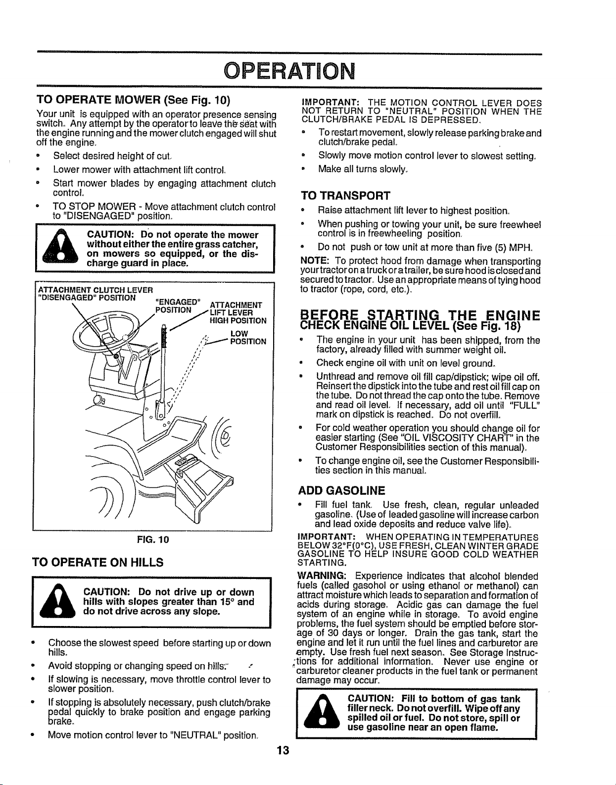
TO OPERATE MOWER (See Fig. 10)
Your unit is equipped with an operator presence sensing
switch° Any attempt by the operatorto leave th_ S_at with
the engine running and the mower clutch engaged will shut
off the engine.
• Select desired height of cut..
• Lower mower with attachment lift control°
• Start mower blades by engaging attachment clutch
control
• TO STOP MOWER - Move attachment clutch control
to "DISENGAGED" position..
_ ,,,,,,,,,,,,,,, , ,, ,
CAUTION: DO not operate the mower
without either the entire grass catcher,
on mowers so equipped, or the dis-
charge guard in place.
ATTACHMENT CLUTCH LEVER
"DISENGAGED" POSITION "ENGAGED" ATTACHMENT
POSITION /LtFT LEVER
HIGH POSITION
LOW
, _ POSITION
IMPORTANT: THE MOTION CONTROL LEVER DOES
NOT RETURN TO "NEUTRAL" POSITION WHEN THE
CLUTCH/BRAKE PEDAL IS DEPRESSED.
° To restart movement, slowly release parking brake and
clutch/brake pedal°
= Slowly move motion control lever to slowest setting..
• Make all turns slowly_
TO TRANSPORT
° Raise attachment lift lever to highest position°
= When pushing or towing your unit, be sure freewheel
control is in freewheeling position.
= Do not push or tow unit at more than five (5) MPH.
NOTE: To protect hood from damage when transporting
your tractor on a truck or atrailer, be sure hood is closed and
secured to tractor_.Use an appropriate means of tying hood
to tractor (rope, cord, etc..).
BEFORE STARTING THE ENGINE
CHECK ENGINE OIL LEVEL (See Fig. 18)
° The engine in your unit has been shipped, from the
factory, already titled with summer weight oil.
FIG. 10
TO OPERATE ON HILLS
CAUTION: Do not drive up or down
hills with slopes greater than 15° and
do not drive across any slope.
° Check engine oil with unit on level ground.
= Unthread and remove oil fill cap/dipstick; wipe oil off.
Reinsert the dipstick into the tube and rest oil fill cap on
the tube. Do not thread the cap onto the tube. Remove
and read oil level. If necessary, add oil until "FULL"
mark on dipstick is reached. Do not overfill°
° For cold weather operation you should change oil for
easier starting (See "OIL VISCOSITY CHART" in the
Customer Res onstbJllt
p Eessection of this manual)
° To change engine oil, see the Customer Responsibili-
ties section in this manual
ADD GASOLINE
° Fill fuel tank. Use fresh, clean, regular unleaded
gasoline_ (Use of leaded gasoline will increase carbon
and lead oxide deposits and reduce valve life)o
IMPORTANT: WHEN OPERATING IN TEMPERATURES
BELOW 32°F(0°C), USE FRESH, CLEAN WINTER GRADE
GASOLINE TO HELP INSURE GOOD COLD WEATHER
STARTING.
WARNING: Experience indicates that alcohol blended
fuels (called gasohol or using ethanol or methanol) can
attract moisture which leads to separation and formation of
acids during storage. Acidic gas can damage the fuel
system of an engine while in storage° To avoid engine
problems, the fuel system should be emptied before stor-
age of 30 days or longer. Drain the gas tank, start the
• Choose the slowest speed before starting up or down
hills_
• Avoid stopping or changing speed on hi//s:- -"
° tf slowing is necessary, move throttle control lever to
slower position°
= If stopping is absolutely necessary, push clutch!brake
pedal quickly to brake position and engage parking
brake°
° Move motion control lever to "NEUTRAL" position.
13
engine and let it run until the fuel lines and carburetor are
empty. Use fresh fuel next season. See Storage lnstruc-
;tions for additional informat_on. Never use engine or
"carburetor cleaner products in the fuel tank or permanent
damage may occur..
_ CAUTION: Fill to bottom of gas tank
filler neck. Do notoveffill. W'ipe offany
spilled oil or fuel. Do not store, spill or
use gasoline near an open flame.
i i ..............................................
OPERATI
.TO START ENGINE (See Fig. 9)
When starting engine for the first time or if engine has
run out of fuel, it will take extra cranking' time "to move
fuel from the tank to the engine,_
• Depress the clutchfDrake pedal and set the parking
brake.
o Place motion control lever in "NEUTRAL" position_
° Move attachment clutch to "DISENGAGED" position,
• Move throttle control lever to "CHOKE" position for'
cold engine start. For warm engine start, move
throttle control to "FAST" position.
° Insert key into ignition and turn key clockwise to
"START" position and release key as soon as en-
gine starts_ Do not run starter continuously for more
than fifteen seconds per minute. If engine does not
start after several attempts, move throttle control to
"FAST" position, wait a few minutes and try again_
° When engine starts, move throttle control to desired
position°
. Allow engine to warm up for a few minutes before
engaging drive or attachment clutch.
NOTE: If at a high altitude (above 3000 feet) or in cold
temperatures (below 32° F), the carburetor fuel mixture
may need to be adjusted for best engine performance.
See "TO ADJUST CARBURETOR" in the Service and
Adjustments section of this manual.
MOWING TIPS
° Tire chains cannot be used when the mower hous-
ing is attached to uniL
• Mower should be properly leveled for best mowin._
performance. See "TO LEVEL MOWER HOUSING
in the Service and Adjustments section of this
manual.
° The left hand side of mower should be used for trim-
ming_
° Drive so that clippings are discharged onto the area
that has been cut. Have the cut area to the right of
the machine. This will resuIt in a more even distri_
bution of clippings and more uniform cutting.
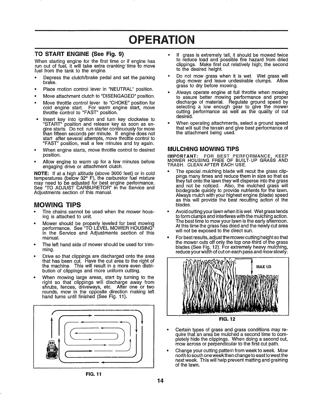
• When mowing large areas, start by turning to the
right so that clippings will discharge away from
shrubs, fences, driveways, etc_ After one or two
rounds, mow in the opposite direction making left
hand turns until finished (See Fig_ 11).
F
f, _,-
m
(
• if grass is extremely tall, it should be mowed twice
to reduce load and possibFe fire hazard from dried
clippings° Make first cut relatively high; the second
to the desired heighL
° Do not mow grass when it is weL Wet grass will
plug mower and leave undesirable clumps.. Allow
grass to dry before mowing
• Always operate engine at full throttle when mowing
to assure better mowing performance and proper'
discharge of material. Regulate ground speed by
selecting a low enough gear to give the mower
cutting performance as well as the quality of cut
desired°
When operating attachments, select a ground speed
that will suit the terrain and give best performance of
the attachment being used.
MULCHING MOWING TIPS
IMPORTANT: FOR BEST PERFORMANCE, KEEP
MOWER HOUSING FREE OF BUILT-UP GRASS AND
TRASH., CLEAN AFTER EACH USE.
= The special mulching blade will recut the grass clip-
pings many times and reduce them in size so that as
they fall onto the lawn they will disperse into the grass
and not be noticed_ Also, the mulched grass will
biodegrade quickly to provide nutrients for the lawn.
Always mulch with your highest engine (blade) speed
as this will provide the best recutting action of the
blades.
= Avoid cutting your lawn when it is wet, Wet grass tends
to form clumps and interferes with the mulching action.
The best time to mow your' lawn is the early afternoon.
At this time the grass has dried and the newly cut area
will not be exposed to the direct sun1,
° For best results, adjust the mower cutting height so that
the mower cuts off only the top one-third of the grass
blades (See Fig, 12). For extremely heavy mulching,
reduce your width of cut on each pass and mow slowly.
FIG. 12
MAX 1/3
. Certain types of grass and grass conditions may re-
quire that an area be mulched a second time to com-
pletely hide the clippings. When doing a second cut,
mow across or perpendicular to tile first cut path.
o Change your cutting pattern from week to week° Mow
north to south one week then change to east to west the
next week. This will help prevent matting and grairiing
of the lawn.
FIG. 11
14
CUSTOMER RESPO
...................ill ii .......
ILITIES
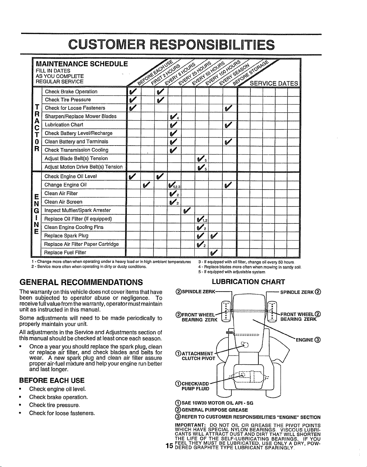
Check BrakeOperation If
CheckTire Pressure .... _' _ .............
Checkfor LooseFasteners _#1
_R
A Sharpen/ReplaceM'ow;rBlades tf4
T CheckBatteryLeveiiRecharge ........ _ .......
0 Clean Batter,.#and Terminals V # ,
a Check Transmission Cooling .... I_
Adjust BladeBelt(s)Tension t_s
AdjustMotionDrive Belt(s)Tension Ks
l
1_ R ,,,,,,,, _, ,
, .-. , ..........
v'
3 - If equipped with oil fitter, change oil every 50 hours,
4 - Replace blades more ellen when mowing in sandy soit.
5 - tl equipped with adjustable system
Check EngineOilLevel If If
Change EngineOil ...... ' _' ;_'_.2,3; ' '
E Clean Air Filter VI2
N CleanAir Screen , _,/2 ...........
G InspectMuffler/SparkArrester _/'
I ReplaceOil Filter (if equipped) _,2
........, ...................'......
ReplaceSpark Plug _ _#'
ReplaceAir FilterPaper'Cartridge .............. V#'2.............
ReplaceFuel Filter
I - Change more olten when operating under a heavy Iced or tn high ambien_ temperalures
2 _Service more ellen when operating in ditty or dusty conditions..
GENERAL RECOMMENDATIONS
The warranty on thisvehicle does not cover itemsthat have
been subjected to operator abuse or negligence. To
receive full value from the warranty, operator must maintain
unit as instructed in this manual,.
Some adjustments will need to be made periodically to
properly maintain your unit..
All adjustments in the Service and Adjustments section of
this manual should be checked at least once each season..
Once a year you should replace the spark plug, clean
or replace air filter, and check blades and belts for
wear. A new spark plug and clean air filter assure
proper air-fuel mixture and help your engine run better
and last longer.
BEFORE EACH USE
• Check engine oil level.
= Check brake operation.
', Check tire pressure.
° Check for loose fasteners.
15
(_)SPINDLE
LUBRICATION CHART
SPINDLE ZERK (_
BEARING ZERK
®
CLUTCH PIVOT
(_)CHECWADD _"
PUMP FLUID
(_)SAE lOW30 MOTOR OIL API - SG
(_) GENERAL PURPOSE GREASE
I _ENGINE(:_
(_) REFER TO CUSTOMER RESPONSIBILITIES "ENGINE" SECTION
IMPORTANT: DO NOT OIL OR GREASE THE PIVOT POINTS
WHICH HAVE SPECIAL NYLON BEARINGS, VISCOUS LUBRI-
CANTS WILL ATTRACT DUST AND DIRT THAT WILL SHORTEN
THE LIFE OF THE SELF-LUBRICATING BEARINGS. IF YOU
FEEL THEY MUST BE LUBRICATED, USE ONLY A DRY, POW-
DERED GRAPHITE TYPE LUBRICANT SPARINGLY..
CUSTOMER ILITIES
TRACTOR
Always observe safety rules when performing any main-
tenance
BRAKE OPERATION
If unit requires more than six (6) feet stopping distance at
high speed in highest gear', than brake must be adjusted.
(See "TO ADJUST BRAKE" in Service and Adjustments
section of this manual)_
TIRES
° Maintain proper air pressure in all tires (See "PROD-
UCT SPECIFICATIONS" on page 3 of this manual)..
• Keep tires free of gasoline, oil, or insect control chemi-
cals which can harm rubber.
o Avoid stumps, stones, deep ruts, sharp objects and
other hazards that may cause tire damage.
BLADE CARE
For best results mower blades must be kept sharp,. Re-
place bent or damaged blades.
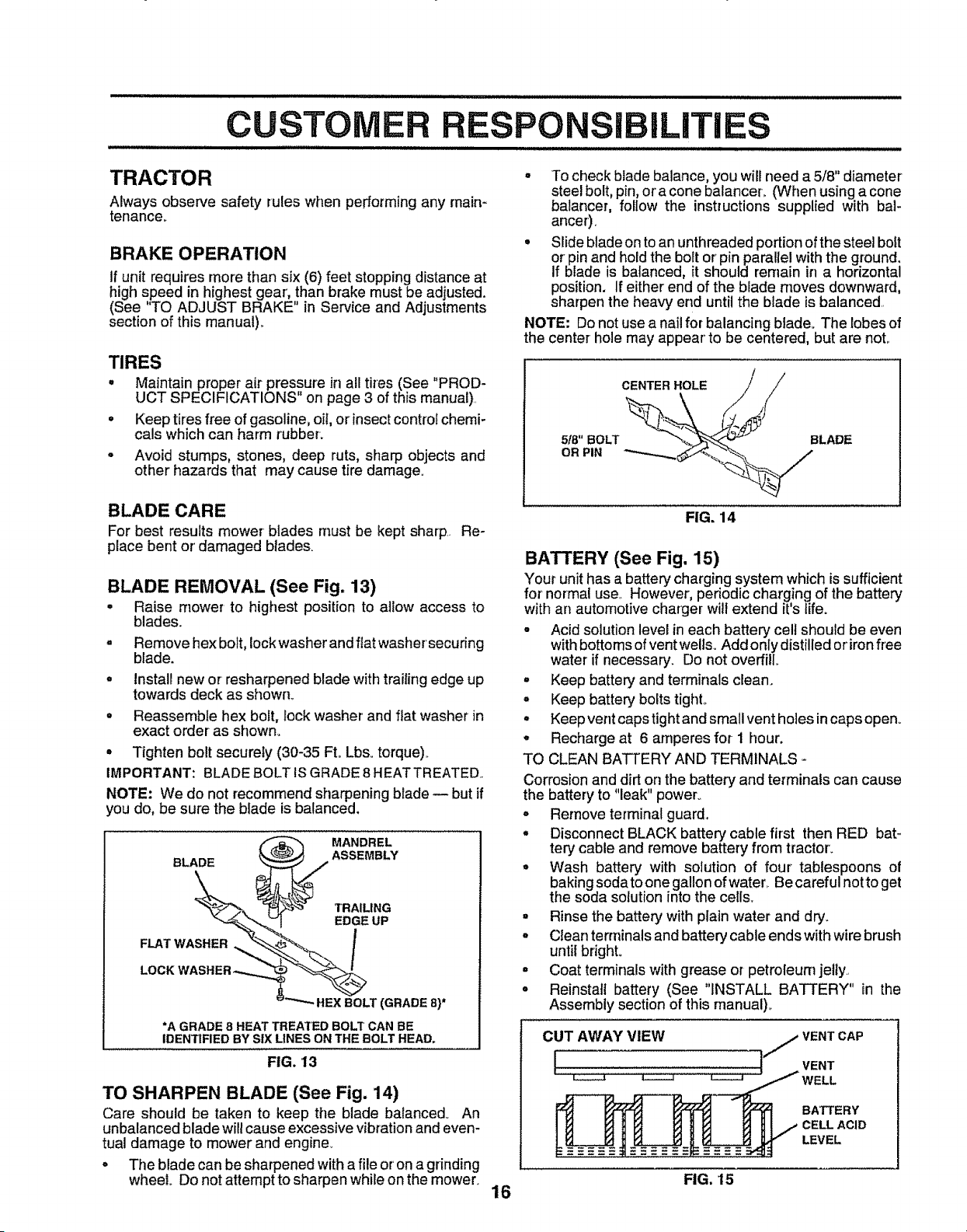
BLADE REMOVAL (See Fig. 13)
° Raise mower to highest position to allow access to
blades.
. Remove hex bolt, Iockwasher and ftat washer securing
blade.
• Install new or resharpened blade with trailing edge up
towards deck as shown_
• ReassernbIe hex bolt, lock washer' and ffat washer in
exact order as shown°
° Tighten bolt securely (30-35 Ft. Lbs. torque)..
IMPORTANT: BLADE BOLT IS GRADE 8 HEATTREATED.,
NOTE: We do not recommend sharpening blade -- but if
you do, be sure the blade is balanced.
_ MANDREL
BLADE ASSEMBLY
SHER_" _ TRAILING
EDGE UP
FLAT WA i_LT
LOCK WASHER _'_"
(GRADE 8)*
*A GRADE 8 HEAT TREATED BOLT CAN BE
IDENTIFIED BY SIX LINES ON THE BOLT HEAD,
FIG. 13
TO SHARPEN BLADE (See Fig. 14)
Care should be taken to keep the blade balanced_ An
unbalanced blade will cause excessive vibration and even-
tual damage to mower and engine_
° The blade can be sharpened with a file or on a grinding
wheel Do not attempt to sharpen while on the mower.
• To check blade balance, you will need a 5/8" diameter
steel bolt, pin, or a cone balancer. (When using a cone
balancer, follow the instructions supplied with bal-
ancer),
• Slide blade on toan unthreaded portionof the steel bolt
or pin and holdthe bolt or pin parallel with the ground,
If blade is balanced, it should remain in a horizontal
position. If either end of the biade moves downward,
sharpen the heavy end untilthe blade is balanced..
NOTE: Donot use a nail for balancing blade. The lobesof
the center hole may appear to be centered, but are not.
CENTER HOLE .,///
518"0RPINBOLT__BLADE
FIG, 14
BATTERY (See Fig, 15)
Your unithas a battery charging system which is sufficient
for normal use.. However, periodic charging of the battery
with an automotivecharger will extend it's tife.
- Acid solution level in each battery cell should be even
withbottoms ofventwells., Add only distilled or'ironfree
water if necessary. Do not overfill.
° Keep battery and terminals clean.
° Keep battery bolts tighL
° Keep vent caps tightand small vent holes incaps open°
• Recharge at 6 amperes for 1 hour,
TO CLEAN BATTERY AND TERMINALS -
Corrosionand dirt on the battery and terminals can cause
the battery to "leak" power°
° Remove terminal guard.
° Disconnect BLACK battery cable first then RED bat-
tery cable and remove battery from tractor'.
• Wash battery with solution of four tablespoons of
baking soda to one gallon of water,. Be careful not to get
the soda solution into the cells.
° Rinse the battery with plain water and dry.
• Clean terminals and battery cable ends with wire brush
until bright°
° Coat terminals with grease or petroleum jelly..
• Reinstall battery (See "INSTALL BATTERY" in the
Assembly section of this manual)_
CUT AWAY VIEW
BATTERY
LEVEL
FIG. 15
16
CU RESPON
ii i lllll .................................. llllL
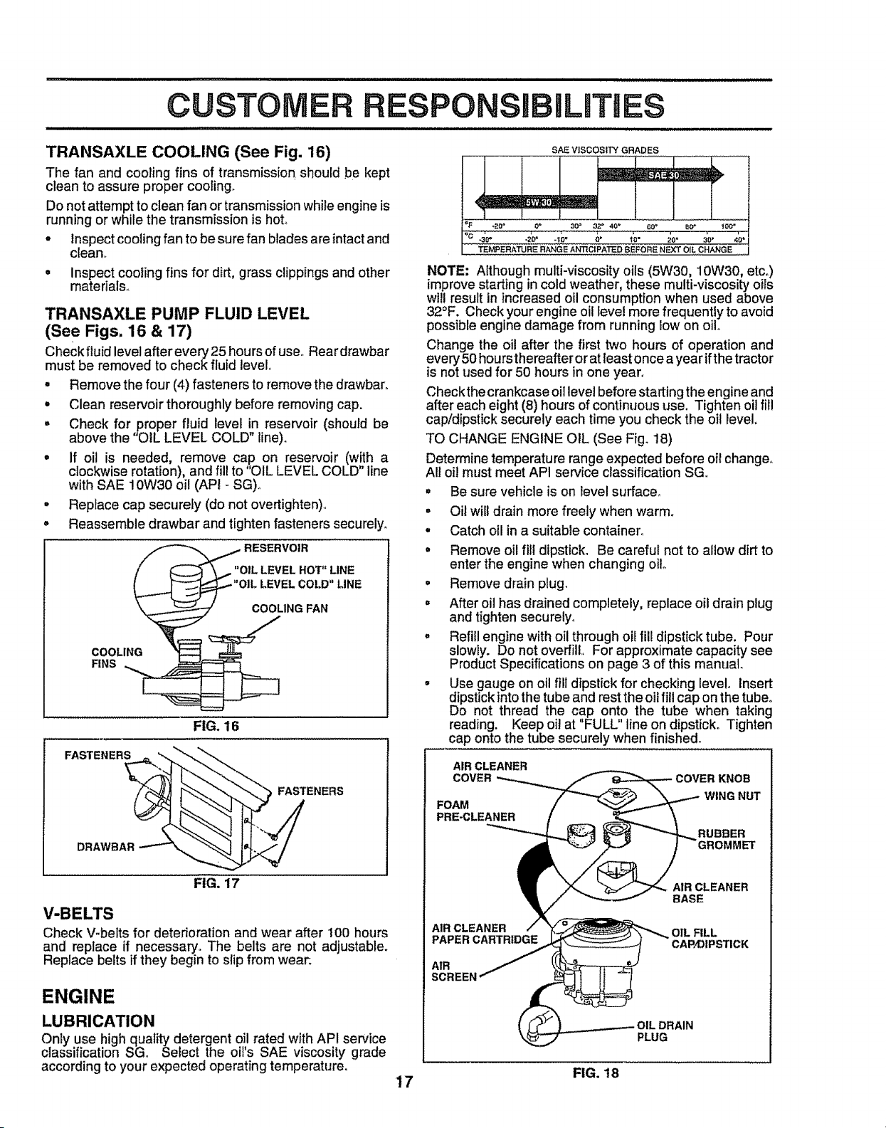
TRANSAXLE COOLING (See Fig. 16)
The fan and cooling fins of transmission, should be kept
clean to assure proper cooling.
Do not attempt to clean fan or transmission while engine is
running or while the transmission is hot°
- Inspect cooling fan to be sure fan blades are intact and
clean,_
= Inspect cooling fins for dirt, grass clippings and other
materials°
TRANSAXLE PUMP FLUID LEVEL
(See Figs. 16 & 17)
Check fluid level after every 25 hours ofuse,,Rear drawbar
must be removed to check fluid level
• Remove the four (4) fasteners to remove the drawbar_
• Clean reservoir thoroughly before removing cap.
° Check for,_roper fluid level in reservoir (should be
above the OIL LEVEL COLD" line).
° If oil is needed, remove cap on reservoir (with a
clockwise rotation), and fil! to "OIL LEVEL COLD" line
with SAE 10W30 oil (API - SG)o
° Replace cap securely (do not overtighten),,
° Reassemble drawbar and tighten fasteners securely,
RESERVOIR
"OIL LEVEL HOT" LINE
LEVEL COt.D" LINE
COOLING FAN
COOLING
FINS
FIG, 16
FASTE.ER#..
__ FASTENERS
DRAWBAR ---""
FIG. 17
V-BELTS
Check V-belts for deterioration and wear after 100 hours
and replace if necessary,, The belts are not adjustable.
Replace belts if they begin to slip from wear.
ENGINE
LUBRICATION
Only use high quatity detergent oil rated with API service
classification SG_ Select the oil's SAE viscosity grade
according to your expected operating temperature.
SAE VISCOSITY GRADES
TEMPERATURE RANGE AN'RC|PA'I'ED EEFORE NEXT OIL CHANGE
NOTE: Although multi-viscosity oils (5W30, 10W30, etc,)
improve starting in cold weather, these multi-viscosity offs
will result in increased oil consumption when used above
32°F. Check your engine oil level more frequently to avoid
possible engine damage from running low on oil
Change the oil after the first two hours of operation and
every 50 hours thereafter or at least once a year ifthe tractor
is not used for 50 hours in one year.
Checkthe crankcase oil level before starting the engine and
after each eight (8) hours of continuous use. Tighten oil fill
cap/dipstick securely each time you check the oil level.
TO CHANGE ENGINE OIL (See Fig. t8)
Determine temperature range expected before oil change,
All oil must meet API service classification SGo
° Be sure vehicle is on level surface_,
° Oil will drain more freely when warm.
• Catch ofl in a suitable container.
° Remove oil fill dipstick. Be careful not to allow dirt to
enter the engine when changing oilo
° Remove drain plug.
. After oil has drained completely, replace oil drain plug
and tighten securely.
. Refill engine with oil through oil fill dipstick tube. Pour
slowly. Do not overfill,, For approximate capacity see
Product Specifications on page 3 of this manual°
• Use gauge on oil fill dipstick for checking level,, Insert
dipstick intothe tube and rest the oil fill cap on the tube.
Do not thread the cap onto the tube when taking
reading. Keep oil at "FULL" line on dipstick° Tighten
cap onto the tube securely when finished.
AIR CLEANER
COVER
FOAM
PRE-CLEANER
COVER KNOB
WING NUT
RUBBER
AIR CLEANER
BASE
AIR CLEANER OIL FILL
PAPER CARTRIDGE CAP/DIPSTICK
AIR
OIL DRAIN
PLUG
FIG. 18
17
CUSTOMER
CLEAN AIR SCREEN (See Fig. 18)
Air screen must be kept free of dirt and chaff to prevent
enginedamage from overheating. Clean witha wirebrush
or compressed air to remove dirt and stubborn dried gum
fibers°
AIR FILTER (See Fig. 18)
Your engine will not run properly using a dirty air filter'.
Clean the foam pro-cleaner element after every 25 hours of
operation or every season. Service paper cartridge every
100 hours or every season, whichever occurs first°
Service air cleaner more often under dusty conditions.
ill,illii i i i
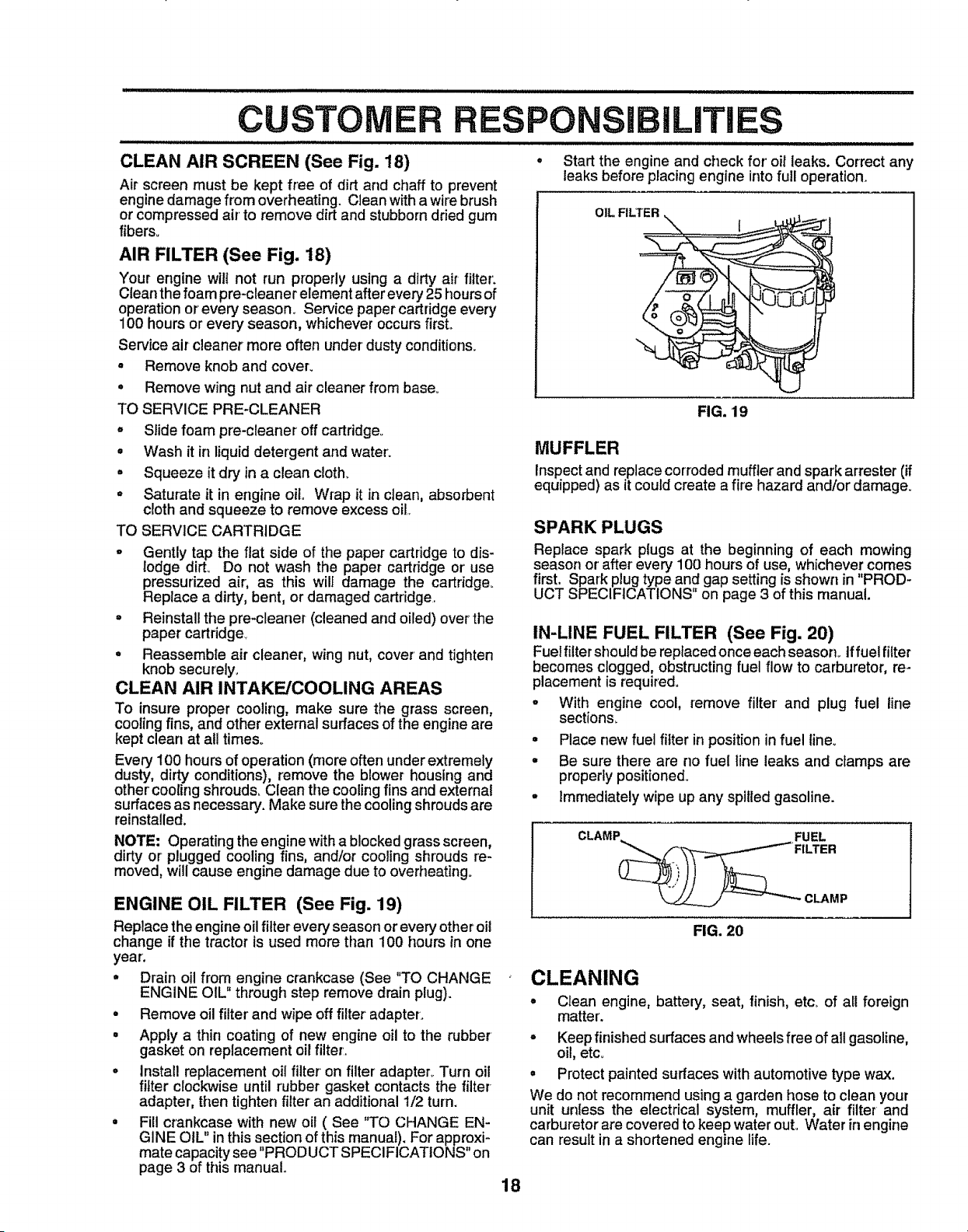
IBI
Start the engine and check for' oil leaks. Correct any
leaks before placing engine into full operation.
OIL FILTER
= Remove knob and cover.
• Remove wing nut and air cleaner from base°
TO SERVICE PRE-CLEANER
° Slide foam pro-cleaner off cartridge_
• Wash it in liquid detergent and water:
° Squeeze it dry in a clean c!oth_
° Saturate it in engine oil Wrap it in clean, absorbent
cloth and squeeze to remove excess oil
TO SERVICE CARTRIDGE
FIG. 19
MUFFLER
Inspectand replace corroded muffter and spark arrester (if
equipped) as it could create a fire hazard and/or damage.
o Gently tap the flat side of the paper cartridge to dis-
lodge dirt° Do not wash the paper cartridge or' use
pressurized air; as this will damage the cartridge.
Replace a dirty, bent, or damaged cartridge.
° Reinstall the pre-cleaner (cleaned and oiled) over the
paper cartridge_
• Reassemble air cleaner, wing nut, cover' and tighten
knob securely,
CLEAN AIR INTAKE/COOLING AREAS
To insure proper cooling, make sure the grass screen,
cooling fins, and other external surfaces of the engine are
kept clean at atl times°
Every 100 hours of operation (more often under extremely
dusty, dirty conditions), remove the blower housing and
other' cooling shrouds. Clean the cooling fins and external
surfaces as necessary. Make sure the cooling shrouds are
reinstalled.
NOTE; Operating the engine with a blocked grass screen,
dirty or plugged cooling fins, and/or cooling shrouds re-
moved, will cause engine damage due to overheating.
SPARK PLUGS
Replace spark plugs at the beginning of each mowing
season or' after' every 100 hours of use, whichever comes
first. Spark plug type and gap setting is shown in PROD-
UCT SPECIFICATIONS" on page 3 of this manual,
IN-LINE FUEL FILTER (See Fig. 20)
Fuel filter should be repfaced once each season_ If fuel filter
becomes clogged, obstructing fuel flow to carburetor, re-
placement is required.
o With engine cool, remove filter and plug fuel line
sections.
° Place new fuel filter in position in fuel lineo
° Be sure there are no fuel line leaks and clamps are
properly positioned.
• Immediately wipe up any spilled gasoline.
ENGINE OIL FILTER (See Fig. 19)
Replace the engine oil filter every season or every other oil
change if the tractor ts used more than 100 hours in one
year.
° Drain oil from engine crankcase (See "TO CHANGE
ENGINE OIL" through step remove drain plug).
° Remove oil filter and wipe off filter' adapter.
° Apply a thin coating of new engine oil to the rubber
gasket on replacement oil filter'.
° install replacement oil filter on filter' adapter.. Turn oil
filter clockwise until rubber gasket contacts the filter
adapter, then tighten filter an additional 1/2 turn.
= Fill crankcase with new oil ( See "TO CHANGE EN-
GINE OIL" in this section of this manual). For approxi-
mate capacity see "PRODUCT SPECIFICATIONS" on
page 3 of this manual..
FIG. 20
CLEANING
° Clean engine, battery, seat, finish, etc. of aU foreign
matter.
° Keep finished surfaces and wheels free of alt gasoline,
oil, etco
° Protect painted surfaces with automotive type wax.
We do not recornrnend using a garden hose to clean your
unit unless the electrical system, muffler, air filter and
carburetor are covered to keep water out. Water in engine
can result in a shortened engine life.
18
SERVICE AND ADJUSTMENTS
i i iilll i i lll illlllll ill i
CAUTION: BEFORE PERFORMING ANY SERVICE OR ADJUSTMENTS:
o Depress clutch!brake pedal fully and set parking brake.
o Place motion control lever in "NEUTRAL" position.
= Place attachment clutch in "DISENGAGED" position,
o Turn ignition key "OFF" and remove key.
• Make sure the blades and all moving parts have completely stopped.
o Disconnect spark plug wire from spark plug and place wire where it cannot come in contact with
plug.
............................ ,,, ,,,, ,,,,, llIHIH,,lllll I lllll INIIHlll
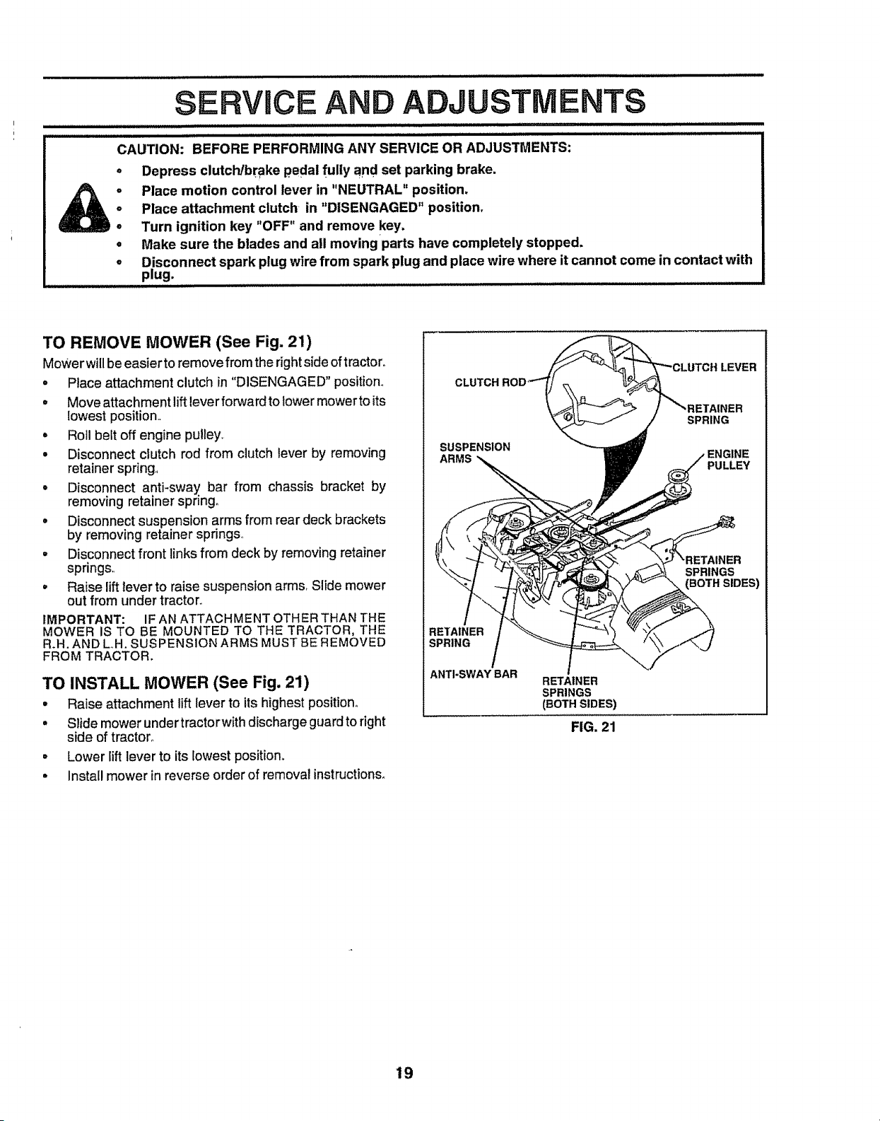
TO REMOVE MOWER (See Fig. 21)
Mower willbe easier to remove from the rightside oftractor.
, Place attachment clutch in "DISENGAGED" position
, Move attachment liftleverfor,_Jardto lower mowerto its
iowest position
° Roll belt off engine pulley.
• Disconnect clutch rod from clutch lever by removing
retainer spring.,
° Disconnect anti-sway bar from chassis bracket by
removing retainer spring,,
° Disconnect suspension arms from rear deck brackets
by removing retainer springs.,
° Disconnect front links from deck by removing retainer
springs,,
° Raise lift lever to raise suspension arms, Slide mower
out from under tractor.
IMPORTANT: IF AN ATTACHMENT OTHER THAN THE
MOWER IS TO BE MOUNTED TO THE TRACTOR, THE
R.H. AND LH. SUSPENSION ARMS MUST BE REMOVED
FROM TRACTOR.
TO INSTALL MOWER (See Fig. 21)
• Raise attachment lift lever to its highest position°
° Slide mower under tractorwith discharge guard to right
side of tractor°
• Lower lift lever to its lowest position.
• Install mower in reverse order of removal instructions_
CLUTCH
LEVER
SUSPENSION
ARMS
SPRING
PULLEY
'RETAINER
SPRINGS
SIDES)
RETAINER
SPRING
ANTI-SWAYBAR
RETAINER
SPRINGS
(BOTH SIDES)
FIG. 21
19
RViCE A
TO LEVEL MOWER HOUSING
ADJUSTIVl
Adjust the mower while tractor is parked on level ground or
driveway, Make sure tires are properly inflated (See
' PRODUCT SPECIFICATIONS" on page 3)° If tires are
over or under inflated, you will not properly adjust your
mower.
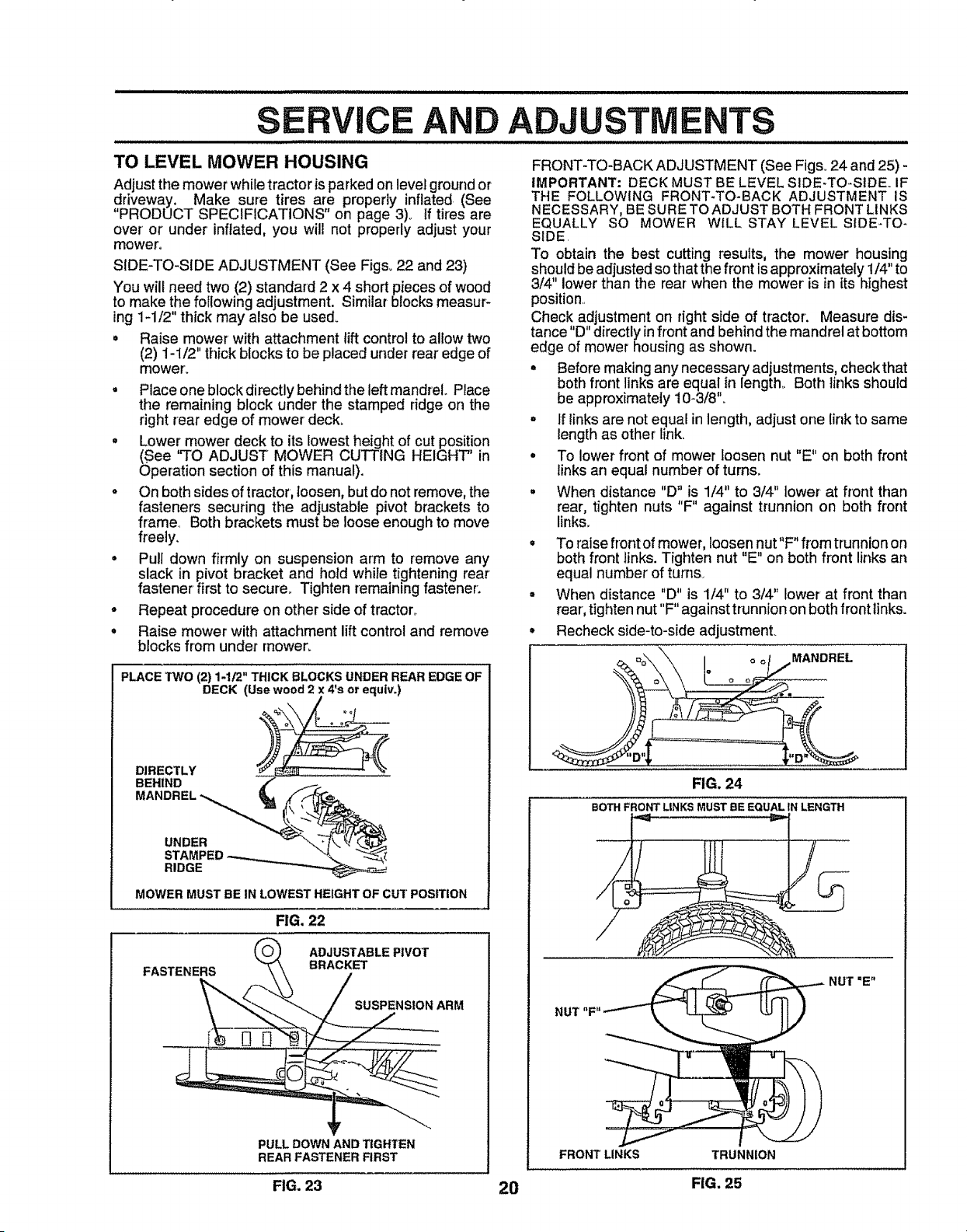
SIDE-TO-SIDE ADJUSTMENT (See Figs° 22 and 23)
You will need two (2) standard 2 x 4 short pieces of wood
to make the following adjustment. Similar blocks measur-
ing 1-1/2" thick may also be used.
• Raise mower with attachment tift control to allow two
(2) 1-1/2" thick blocks to be placed under rear edge of
mowerL
, Place one block directly behind the left mandrel. Place
the remaining block under the stamped ridge on the
right rear edge of mower deck_
, Lower mower deck to its lowest height of cut position
(See "TO ADJUST MOWER CUTTING HEIGHT" in
Operation section of this manual).
o On both sides of tractor, loosen, but do not remove, the
fasteners securing the adjustable pivot brackets to
frame. Both brackets must be loose enough to move
freely.
° Pull down firmly on suspension arm to remove any
slack in pivot bracket and hold while tightening rear
fastener first to secure.. Tighten remaining fastener.
- Repeat procedure on other side of tractor.
• Raise mower with attachment lift control and remove
blocks from under mowen
PLACE TWO (2) 1-1/2" THICK BLOCKS UNDER REAR EDGE OF
DECK (Use wood 2 x 4's or equiv.)
NTS
FRONT-TO-BACK ADJUSTMENT (See Figs° 24 and 25) -
IMPORTANT = DECK MUST BE LEVEL SIDE-TO-SIDE. IF
THE FOLLOWING FRONT-TO-BACK ADJUSTMENT IS
NECESSARY, BE SURE TO ADJUST BOTH FRONT LINKS
EQUALLY SO MOWER WILL STAY LEVEL SIDE-TO-
SIDE,
TO obtain the best cutting results, the mower housing
should be adjusted so thatthe front is approximately 1/4" to
3/4" lower than the rear when the mower' is in its highest
position.,
Check adjustment on right side of tractor. Measure dis-
tance "D" directly in front and behind the mandrel at bottom
edge of mower housing as shown.
• Before making any necessary adjustments, checkthat
both front links are equal in length_ Both links should
be approximately 10-3/8'L
° If tinks are not equal in length, adjust one link to same
length as other link,
° To lower front of mower loosen nut "E" on both front
links an equal number' of turns.
• When distance "D" is 1/4" to 3/4" lower at front than
rear, tighten nuts "F" against trunnion on both front
links.
DIRECTLY
BEHIND
UNDER
RIDGE
MOWER MUST BE IN LOWEST HEIGHT OF CUT POSITION
FIG. 22
PULL DOWN AND TIGHTEN
REAR FASTENER FIRST
° To raise front of mower, loosennut"F" from trunnion on
both front links. Tighten nut "E" on both front links art
equal number' of turns.
° When distance "D" is 1/4" to 3/4" lower at front than
rear, tighten nut"F" against trunnion on both front links.
• Recheck side-to-side adjustment.
MANDREL
FIG. 24
BOTH FRONT LINKS MUST BE EQUAL IN LENGTH
NUT "F" NUT "E"
FRONT LINKS TRUNNION
FIG. 25
FIG. 23 20
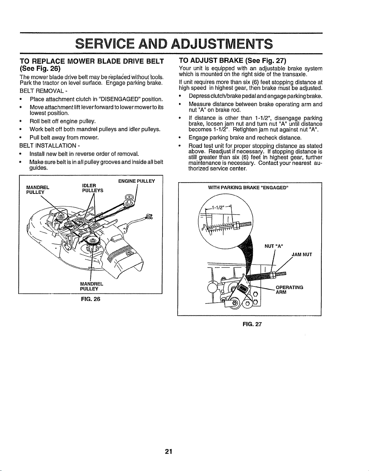
TO REPLACE MOWER BLADE DRIVE BELT
(See Fig. 26)
The mower blade drive belt may be r'epla_ed without_toois.
Park the tractor on level surface. Engage parking brake.
BELT REMOVAL -
• Place attachment clutch in "DISENGAGED" position°
• Move attachment lift lever forward to lower mower to its
lowest position°
° Roll belt off engine puileyo
° Work belt off both mandrel pulleys and idler pulleys.
, Pull belt away from mower.
BELT INSTALLATION -
, install new belt in reverse order of removal.
o Make sure belt isin all pulley grooves and inside all belt
guides.
II/ll/llJll/lllllilljll IIIIlll
ERVJCEANDA USTMENTS
=='===N.NllllIll' = =l
TO ADJUST BRAKE (See Fig. 27)
Your unit is equipped with an adjustable brake system
which is mounted onthe right side of the transaxleo
If unit requires more than six (6) feet stopping distance at
high speed in highest gear, then brake must be adjusted.
• Depress clutch/brake pedal and engage parking brake.
° Measure distance between brake operating arm and
nut 'A" on brake rod.
° If distance is other than 1-1/2", disengage parking
brake, loosen jam nut and turn nut "A" until distance
becomes 1-1/2". Retighten jam nut against niJt "A"o
° Engage parking brake and recheck distance°
° Road test unit for proper stopping distance as stated
above. Readjust if necessary, if stopping distance is
still greater than six (6) feet in highest gear, further
maintenance is necessary. Contact your nearest au-
thorized service center_
MANDREL IDLER
PULLEY PULLEYS
ENGINE PULLEY
MANDREL
PULLEY
FIG. 26
WITH PARKING BRAKE "ENGAGED"
NUT "A"
JAM NUT
OPERATING
FIG. 27
21
ERVICE ADJUSTMENTS
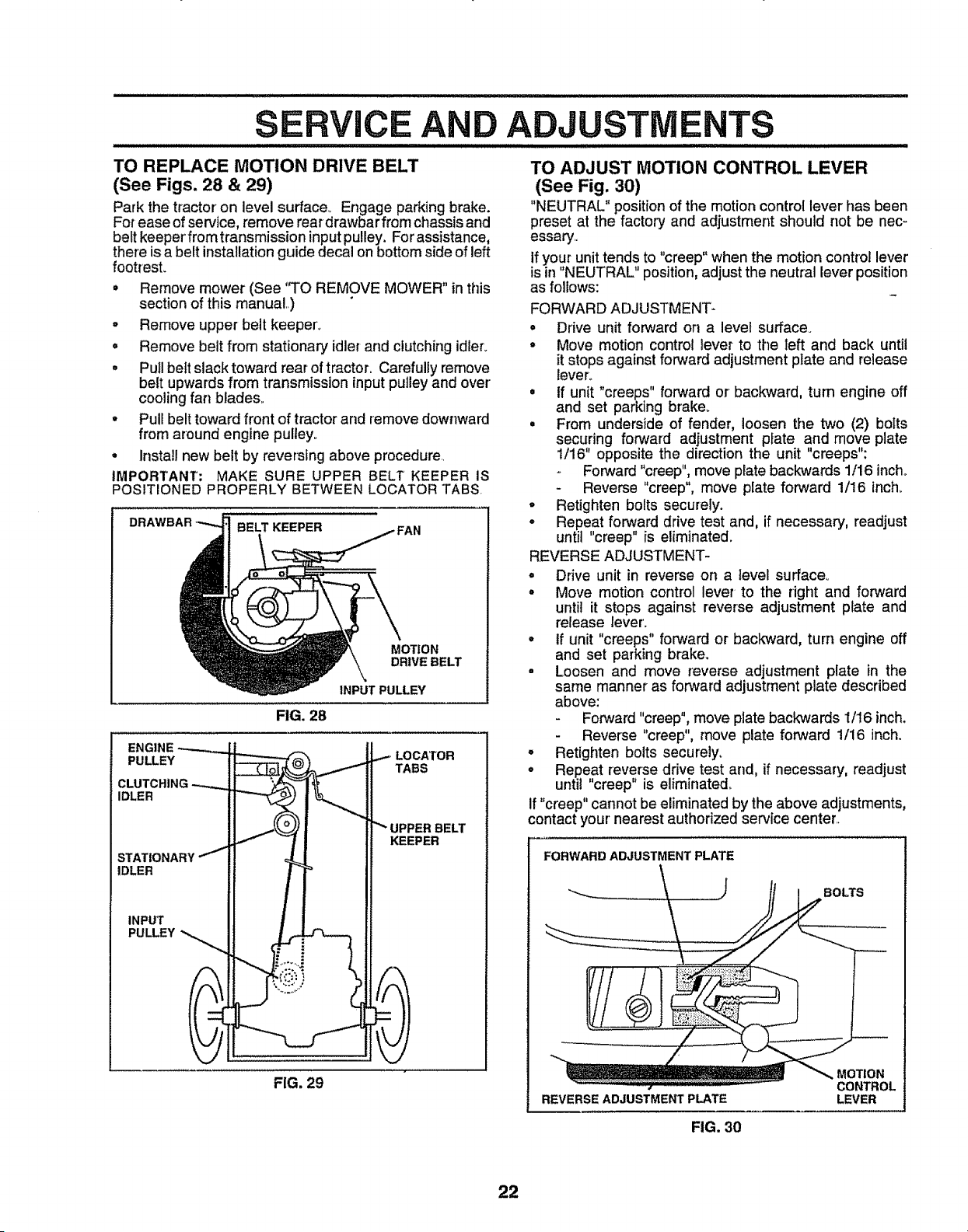
TO REPLACE MOTION DRIVE BELT
(See Figs. 28 & 29)
Park the tractor on level surface_ Engage parking brake.
For ease of service, remove rear drawbar frorn chassis and
belt keeper from transmission inputpulley. For assistance,
there is a belt installation guide decal on bottom side of left
footresL
• Remove mower (See "TO REMOVE MOWER" in this
section of this manual..)
o Remove upper belt keeper°
• Remove belt from stationary idler and clutching idler_
° Pull belt slack toward rear of tractor. Carefully remove
belt upwards from transmission input pulley and over
cooling fan blades.,
° Pull belt toward front of tractor and remove downward
from around engine pulley°
° Install new belt by reversing above procedure.
IMPORTANT; MAKE SURE UPPER BELT KEEPER IS
POSITIONED PROPERLY BETWEEN LOCATOR TABS.
DR
BELT KEEPER
MOTION
DRIVE BELT
INPUT PULLEY
FIG. 28
CLUTC.,NG-- il
II _....-%_)J ll"" UPPERBELT
-! !1 KEEPER
FIG. 29
TO ADJUST MOTION CONTROL LEVER
(See Fig. 30)
"NEUTRAL" position of the motion control lever has been
preset at the factory and adjustment should not be neco
essary,
If your unit tends to "creep" when the motion control lever
is in "NEUTRAL" position, adjust the neutral lever position
as follows:
FORWARD ADJUSTMENT-
= Drive unit forward on a level surface.
• Move motion control lever to the left and back until
it stops against forward adjustment plate and release
lever°
• If unit "creeps" forward or backward, turn engine off
and set parking brake.
• From underside of fender, loosen the two (2) bolts
securing forward adjustment p_ate and move plate
1/16" opposite the direction the unit "creeps":
Forward "creep", move plate backwards 1/16 inch.
Reverse "creep", move plate forward 1/16 inch.
° Retighten bolts securely.
o Repeat forward drive test and, if necessary, readjust
until "creep" is eliminated.
REVERSE ADJUSTMENT-
= Drive unit in reverse on a level surface°
° Move motion control lever to the right and forward
until it stops against reverse adjustment plate and
release lever'_
= tf unit "creeps" forward or backward, turn engine off
and set parking brake.
• Loosen and move reverse adjustment plate in the
same manner as forward adjustment plate described
above:
Forward "creep", move plate backwards 1/16 inch.
Reverse "creep", move plate forward 1/16 inch.
o Retighten bolts securely_
° Repeat reverse drive test and, if necessary, readjust
until "creep" is eliminated.
If "creep" cannot be eliminated by the above adjustments,
contact your' nearest authorized service center..
FORWARD ADJUSTMENT PLATE
BOLTS
REVERSE ADJUSTMENT PLATE
MOTION
CONTROL
LEVER
FIG. 30
22
SERVICE AND
TO ADJUST STEERING WHEEL ALIGNMENT
If steering wheel crossbars are not horizontal (left to right)
when wheels are positioned straight, forward, remove
steering wheel and reassemble per instructions in the
Assembly section of this manual..
FRONT WHEEL TOE-IN/CAMBER
The front wheel toe-in and camber are not adjustable on
your tractor. If damage has occurred to affect the front
wheel toe-in or camber, contact your nearest authorized
service center.
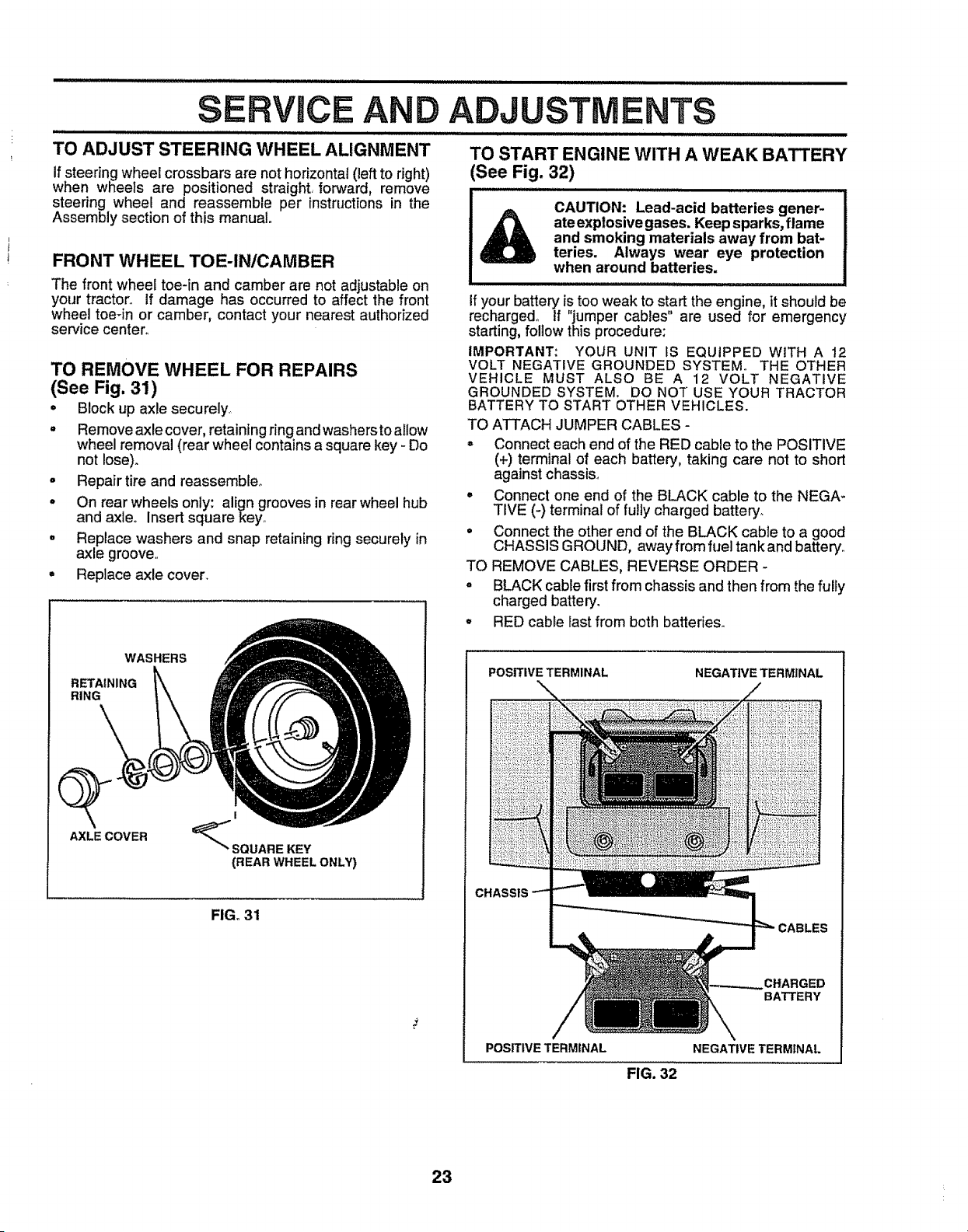
TO REMOVE WHEEL FOR REPAIRS
(See Fig. 31)
* Block up axle securely
° Remove axle cover, retaining ring and washersto allow
wheel removal (rear wheel contains a square key - Do
ADJUSTMENTS
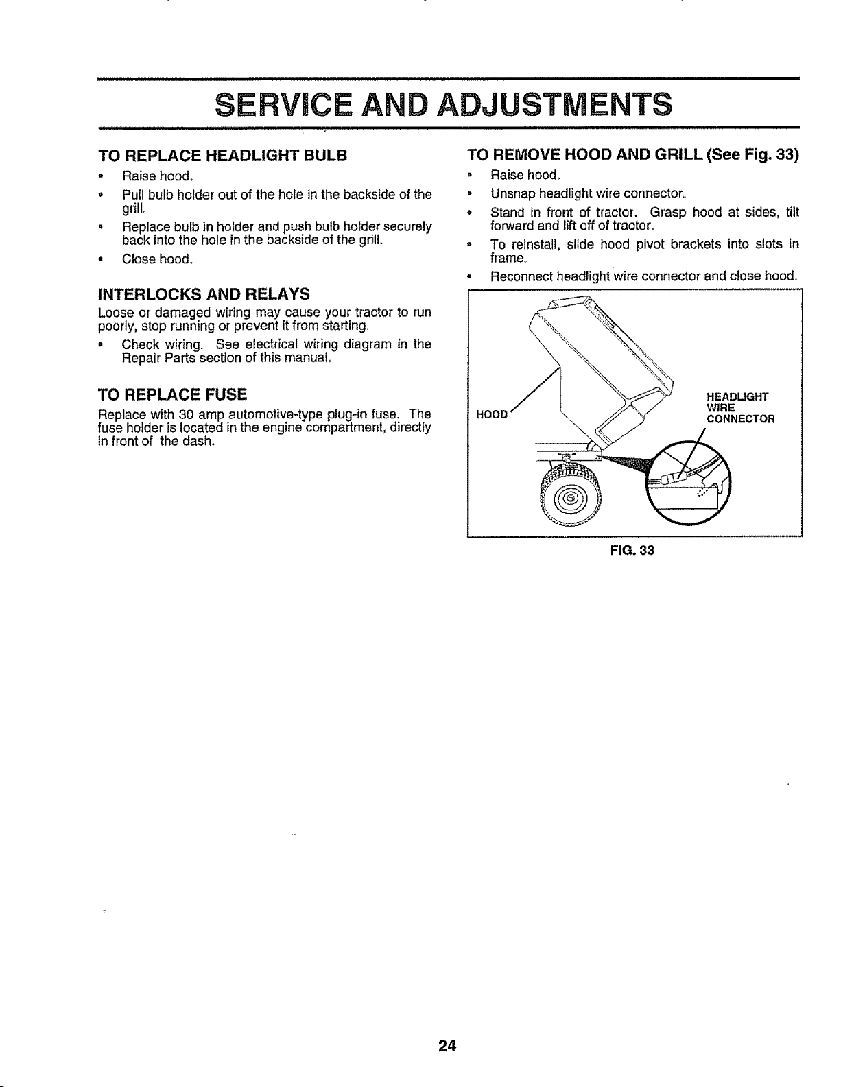
TO START ENGINE WITH A WEAK BATTERY
(See Fig. 32)
CAUTION: Lead-acid batteries gener-
ate explosive gases. Keep sparks, flame
and smoking materials away from bat-
teries. Always wear eye protection
when around batteries.
If your battery is too weak to start the engine, it should be
recharged,. If "jumper cables" are used for emergency
starting, follow this procedure:
IMPORTANT: YOUR UNIT IS EQUIPPED WITH A 12
VOLT NEGATIVE GROUNDED SYSTEM. THE OTHER
VEHICLE MUST ALSO BE A 12 VOLT NEGATIVE
GROUNDED SYSTEM. DO NOT USE YOUR TRACTOR
BATTERY TO START OTHER VEHICLES.
TO ATTACH JUMPER CABLES -
° Connect each end of the RED cable to the POSITIVE
not lose).
° Repair tire and reassemble°
° On rear wheels only: align grooves in rear wheel hub
and axleo Insert square key°
• Replace washers and snap retaining ring securely in
axle groove..
= Replace axle cover.
WASHERS
RETAINING
RING
Q
AXLE COVER
I
"'" SQUARE KEY
(REAR WHEEL ONLY)
FIGo31
(+) terminal of each battery, taking care not to short
against chassis.,
° Connect one end of the BLACK cable to the NEGA-
TIVE (-) terminal of fu!ly charged battery.
• Connect the other end of the BLACK cable to a good
CHASSIS GROUND, away from fuel tank and battery..
TO REMOVE CABLES, REVERSE ORDER
o BLACK cable first from chassis and then from the fully
charged battery.
, RED cable last from both batteries.
POSITIVE TERMINAL
NEGATIVE TERMINAL
CHASSIS
CHARGED
BATTERY
POSITIVE TERMINAL NEGATIVE TERMINAL
FIG. 32
23
S RVICE AND ADJUSTM
TO REPLACE HEADLIGHT BULB
- Raise hood.,
= Pull bulb holder out of the hole in the backside of the
grill,,
• Replace bulb in holder and push bulb holder securely
back into the hole inthe backside of the grill
• Close hood_
INTERLOCKS AND RELAYS
Loose or damaged wiring may cause your tractor to run
poorly, stop running or prevent it from starting
° Check wiring See electrical wiring diagram in the
Repair Parts section of this manual.
TO REPLACE FUSE
Replace with 30 amp automotive-type plug-in fuse. The
fuse holder is located inthe engine compartment, directly
in front of the dash.
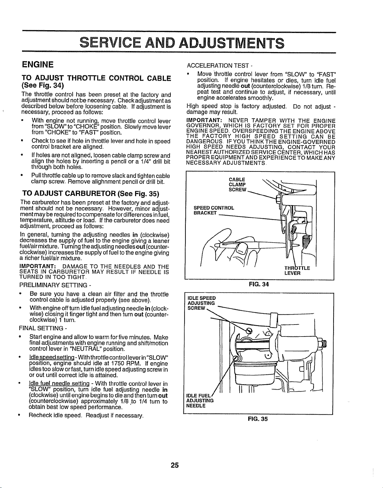
TO REMOVE HOOD AND GRILL (See Fig. 33)
• Raise hood_
. Unsnap headlight wire connector_
° Stand in front of tractor'. Grasp hood at sides, tilt
forward and lift off of tractor.
o To reinstall, slide hood pivot brackets into slots in
frame_
° Reconnect headlight wire connector and close hood.
HOOD
HEADLIGHT
WIRE
CONNECTOR
FIG. 33
24
ENGINE
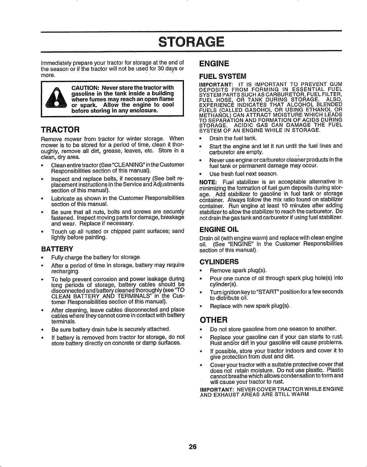
TO ADJUST THROTTLE CONTROL CABLE
(See Fig. 34)
The throttle control has been preset at the factory and
adjustment should notbe necessary° Check adjustment as
described below before loosening cable_ If adjustment is
necessary, proceed as follows:
o With engine not running, move throttle control lever
from "SLOW" to "CHOKE" position. Slowly move lever
from "CHOKE" to "FAST" position.
° Check to see if hole in throttle lever and hole inspeed
control bracket are aligned.
o If holes are not aligned, loosencable clamp screw and
align the holes by inserting a pencil or a 1/4 drill bit
through both holes.
° Pull throttle cable up to remove slack and tighten cable
clamp screw. Remove alighnment pencil or drill bit.
TO ADJUST CARBURETOR (See Fig. 35)
The carburetor has been preset at the factoryand adjust-
ment should not be necessary. However, m_nor adjust-
ment may be required to compensate for differences infuel,
temperature, altitude or ioado If the carburetor does need
adjustment, proceed as follows:
in general, turning the adjusting needles in (clockwise)
decreases the supply of fuel to the engine giving a leaner
fue!/air mixture. Turning the adjusting needles out (counter-
clockwise) increases the supply of fuel to the engine giving
a richer fuel/air mixture.
IMPORTANT: DAMAGE TO THE NEEDLES AND THE
SEATS IN CARBURETOR MAY RESULT IF NEEDLE IS
TURNED IN TOO TIGHT_
PRELIMINARY SETTING
• Be sure you have a clean air filter and the throttle
control cable is adjusted properly (see above)..
° With engine off turn idle fuel adjusting needle in (clock-
wise) closing it finger tight and then turn out (counter*
clockwise) 1 turn,.
FINAL SETTING -
. Start engine and allow to warm for five minutes. Make
final adjustments with engine running and shift/motion
control lever in "NEUTRAL" position°
• IdlesDeedsetting-Withthrottlecontrolleverin"SLOW"
positi-on, engine should idle at 1750 RPM. If engine
idles too slow or fast, turn idle speed adjusting screw in
or out until correct idle is attained,
° Idle fuel needle settin_q* With throttle control lever in
"SLOW" position, turrl idle fuel adjusting needle in
(clockwise) until engine begins to die and then turn out
(counterclockwise) approximately 1/8 to 1/4 turn to
obtain best low speed performance. "
° Recheck idle speed., Readjust if necessary°
ACCELERATION TEST -
• Move throttle control lever from "SLOW" to "FAST"
position° If engine hesitates or dies, turn idle fuel
adjusting needle out (counterclockwise) 1/8 turn° Re-
peat test and continue to adjust, if necessary, until
engine accelerates smoothly.
High speed stop is factory adjusted. Do not adjust -
damage may result°
IMPORTANT: NEVER TAMPER WiTH THE ENGINE
GOVERNOR, WHICH IS FACTORY SET FOR PROPER
ENGINE SPEED. OVERSPEEDING THE ENGINE ABOVE
THE FACTORY HIGH SPEED SETTING CAN BE
DANGEROUS. IF YOU THINK THE ENGINE-GOVERNED
HIGH SPEED NEEDS ADJUSTING, CONTACT YOUR
NEARESTAUTHORIZED SERVICE CENTER, WHICH HAS
PROPER EQUIPMENT AND EXPERIENCE TO MAKE ANY
NECESSARY ADJUSTMENTS
CABLE \
CLAMP
SCREW
SPEED CONTROL
BRACKET
THF
LEVER
FIG. 34
IDLE SPEED
ADJUSTING
IDLE FUEL
ADJUSTING
NEEDLE
FIG. 35
25
STORAGE
I iiii iiiiiiiii i i
Immediately prepare your tractor for storage at the end of
the season or if the tractor will not be used for 30 days or
more_. "
CAUTION: Never store the tractor with
gasoline in the tank inside a building
where fumes may reach an open flame
or spark. Allow the engine to cool
before storing in any enclosure°
TRACTOR
Remove mower from tractor for winter storage_ When
mower is to be stored for a period of time, clean it thor-
oughly, remove all dirt, grease, leaves, etc. Store in a
clean, dry area.
o Clean entiretractor (See"CLEANING"inthe Customer
Responsibilities section of this manual).
° Inspect and replace belts, if necessary (See belt re-
placement instructionsinthe Service and Adjustments
sectionof this manual)=
° Lubricate as shown in the Customer Responsibilities
section of this manual.
• Be sure that all nuts, bolts and screws are securely
fastened. Inspect moving parts for damage, breakage
and wear. Replace if necessary.
• Touch up all rusted or chipped paint surfaces; sand
lightly before painting..
BATTERY
o Fullycharge the battery for storage°
° After a period of time in storage, battery may require
recharging_
° To help prevent corrosion and power leakage during
long periods of storage, battery cables should be
disconnected and battery cleaned thoroughly(see'q'O
CLEAN BATTERY AND TERMINALS" in the Cus-
tomer Responsibilitiessection of this manual)_
° After cleaning, leave cables disconnected and place
cableswhere they cannot come incontactwithbattery
terminals.
° Be sure battery drain tube is securely attached.
° If battery is removed from tractor' for storage, do not
store battery directly on concrete or damp surfaces.
ENGINE
FUEL SYSTEM
IMPORTANT: IT IS IMPORTANT TO PREVENT GUM
DEPOSITS FROM FORMING iN ESSENTIAL FUEL
SYSTEM PARTS SUCH AS CARBURETOR, FUEL FILTER,
FUEL HOSE, OR TANK DURING STORAGE. ALSO,
EXPERIENCE iNDICATES THAT ALCOHOL BLENDED
FUELS (CALLED GASOHOL OR USING ETHANOL OR
METHANOL) CAN ATTRACT MOISTURE WHICH LEADS
TO SEPARATION AND FORMATION OFACIDS DURING
STORAGE. ACIDIC GAS CAN DAMAGE THE FUEL
SYSTEM OF AN ENGINE WHILE IN STORAGE,
° Drain the fuel tank.
° Start the engine and let it run until the fuel lines and
carburetor are empty.
• Never use engine orcarburetor cleaner productsin the
fuel tank or permanent damage may occur°
o Use fresh fuel next season_.
NOTE: Fuel stabilizer is an acceptable alternative in
minimizing the formation of fuel gum deposits during stor-
age. Add stabilizer to gasoline in fuel tank or storage
container. Always follow the mix ratio found on stabilizer
container. Run engine at least 10 minutes after adding
stabilizer to allow the stabilizer to reach the carburetor. Do
not drain the gas tank and carburetor' if using fuel stabilizer..
ENGINE OIL
Drain oil(withengine warm) and replace with clean engine
oil. (See "ENGINE" in the Customer Responsibilities
section of this manual).
CYLINDERS
• Remove spark plug(s).
° Pour one ounce of oil through spark plug hole(s) into
cylinder(s),
° Turn ignitionkey to"START" position fora few seconds
to distribute oil.
° Replace with new spark plug(s).
OTHER
° Do not store gasoline from one season to another.
° Replace your gasoline can if your can starts to rust.
Rust and/or dirt in your gasoline will cause problems.
° If possible, store your tractor' indoors and cover it to
give protectionfrom dust and dirt..
• Cover yourtractor'witha suitable protectivecoverthat
does not retain moisture. Do not use plastic. Plastic
cannot breathe whichallows condensationto form and
will cause your tractorto rust.
IMPORTANT: NEVER COVER TRACTOR WHILE ENGINE
AND EXHAUST AREAS ARE STILL WARM..
26

iiil.llll,llliii illl.i illll j .,lll,,lll,l,,ll,i, ii IlL i i i_
TROUBLESHOOTING POmNTS
Hll.J ................................... ,i,iui.............................
PROBLEM
Will not start
Hard to start
Engine will not turn over
Engine clicks but will not
start
Loss of power
Excessive vibration
CAUSE
1 Out of fuel
2.. Engine not "CHOKED" properly.
3, Engine flooded
4 Bad spark plug
5. Dirty air fitter
6, Dirty fuel filter.
7.. Water in fuel.
8. Loose or damaged wiring,
9, Carburetor out of adjustment
10,, Engine valves out of adjustment
1. Dirty air filter,,
2, Bad spark plug
3., Weak or dead battery,
4. Dirty fuel filter.
5- Stale or dirty fiJel,
6. Loose or damaged widng..
7o Carburetor out of adjustment
8. Engine valves out of adjustment.,
i,, Clutch/brake pedal not depressed
2, Attachment dutch is engaged.
3 Weak or dead battery
4. Blown fuse,,
5 Corroded batter,] terminals_
6, Loose or damaged wiring.
7, Faulty ignition switch
8 Faulty solenoid or starter.
9. Fautty operator presence switch(as)
1 Weak or dead battery,
2 Corroded battery terminals.
3., Loose or damaged widng,
4. Faulty solenoid or starter,
t., Cutting too much grass/too fast,
2. Throttle in "CHOKE" position.
3 Buird_up of grass, leaves and trash under mower
4, Dirty air rifler..
5 Low oif level!dirty oil.
6. Faulty spark plug
7. Dirty fuel fitter,
8. Stale or dirty fuel,,
9 Water in fuel
10. Spark ptug wtreloose,
11 Dirty engine air screentfine
12, Dtrtylclogged muffler,
13., Loose or damaged wiring°
14 Carburetor out of adjustment,,
15. Engine valves out of adjustmen'!_
1, Worn, bent or toose blade,
2, Bent blade mandrel.
3, Looeeldamaged part(s),
CORRECTION
1,, Fill fuel tank°
2o See "TO START ENGINE" in Operation section,
3. Wait several minutes before attempting to start
4_ ReplacB sparkptug,
5 Clean/replace air filter,
6, Replace fuel filter.
7. Drain fue_ tank and carburetor, refill tank with fresh
gasortne and replace fuel _tter,
8 Check alf wtdng,
9. Contact an authorized service center/department,
10. Contact an authorized service center/department,
1 Clean/replace air filter.,
2. Replace spark plug,
3. Recharge or replace battery
4, Replace fuel filter
5 Drain fuet tank and refill with fresh gasoline,,
6 Check all wtdng,
7 Contact an authorized service center/department,
8, Contact an authorized service centerldepartment.
1 Depress c]utchJbrake pedal
2. Disengage attachment clutch,
3., Recharge or replace battery.
4. Replace fuse,,
5 Clean battery terminals
6. Check all wldng,
7, ChecWreptace Ignition switch.
8. Check/replace soteno]d or starter.
9 Contact an authodzed service center/departmenL
1.. Recharge or replace battery
2, Clean battery terminals
3. Check all wiring
4 Check/replace solenoid or starter,
1, Set in "Higher Cut" position/reduce speed,
2. Adjust throttle control
3 Clean underside of mower houelng_
4, Clean/replace air filter
5, Check oil leve!fchange ell
6. Clean and regap or change spark plug.,
7. Replace fuel fitters,
8. Drain fuel tank and refill with fresh gasoline_
9, Drain fuel tank and carburetor, refill tank with fresh
gasoline and replace fuel filter.
t 0. Connect and tighten spark plug wire
I1. Clean engine air screeniflns_
12. Clean/replace muffler
13_ Check all wtdng
14 Contact an authorized service centerldepartmenL
15 Contact an authodzed service center/department,
1_ Replace blade, Tighten blade bolt
2 Replace blade mandrel.
3 Tighten loose part(s), Replace damaged parts.,
27
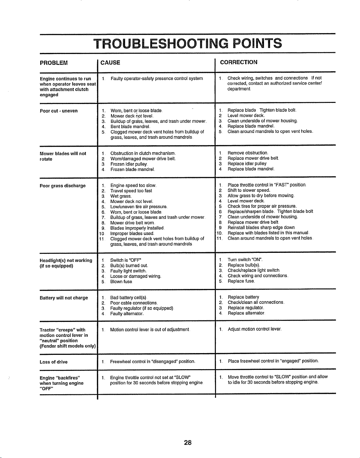
TROUBL
........................................... iii _ iiiiiiiiii i
O0 NG POINTS
PROBLEM
Engine continues to run
when operator leaves seat
with attachment clutch
engaged
Poor cut _ uneven
Mower blades will not
rotate
Poor grass discharge
Headlight(s) not working
(if so equipped)
Battery will not charge
CAUSE
1. Faulty operator-safety presence control system
CORRECTION
1, Check wiring, switches and connections If not
corrected, contact an authodzed service cented
department,
1,. Worn, bent or loose blade,
2. Mower deck not level..
3,, Buildup of gr_ss, reaves, and trash under mower.
4,, Bent blade mandrel,
5, Ctoggsd mower deck vent holes from buildup of
grass, leaves, and trash around mandrels
1, Replace btade Tighten blade bolt,
2 Love! mower deck,
3 Clean underside of mower housing,.
4, Replace blade mandrel,
5, Clean around mandrels to open vent holes,.
Tractor "creeps" with
motion control lever in
"neutral" position
1. Obstruction in clutch mechanism,
2 Wornfdamaged mower drive belt,.
3 Frozen idiot pulley,
4 Frozen blade mandrel,
t. Engine speed too slow.
2. Travel speed too fast
3, Wet grass,
4. Mower deck not level..
5., Lowluneven tire air pressure_
6. Worn, bent or loose blade.
7,. Buildup of grass, leaves and trash under mower.
8. Mower drive belt worn
9o Blades impropedy {nstalled.
10 Improper blades used.
11 Ciogged mower deck vent holes from buildup of
grass, leaves, and trash around mandrels
1 Remove obstruction,,
2 Replace mower ddve belt
3 Replace idler pulley
4 Replace blade mandrel,
1 Place throttle control in "FAST" position
2, Shift to slower speed.
3 Allow grass to dry before mowing,
4 Level mower deck,.
5 Checkttres for proper air pressure_
6 Replace/sharpen biade. T{ghten biade bolt
7, Clean underside of mower housing,,
B. Replace mowerdrive belt,
9 Reinstall blades sharp edge down
10,. Replace with blades listed in this manual
11_ CJean around mandrels to open vent holes,
"l Switch is "OFF"
2. Bulb(s) bumed out,,
3, Faulty light switch,,
4, Loose or damaged widng,,
5. Blown fuse
i, Bad battery cell(s)
2. Poor cable connections
1 Turn switch "ON"_
2, Replace bulb(s),,
3, Check/replace light switch,
4,, Check wiring and connections,
5, Replace fuse.
1. Replace batter'l/
2,. Check/clean all connections,
(Fender shift models only)
Loss of drive
Engine "backfires"
when turning engine
"OFF'*
3. Faulty regulator (if so equipped)
4 Faulty alternator,,
1 Motion control lever is out of adjustment,
1 Freewheel control in "disengaged" position..
1_ Engine throttle control not set at "SLOW"
positionfo_ 30 seconds before stopping engine
3, Replace regulator.,
4, Replace alternator
1. Adjust motion cantrol lever.,
1. Place freewheel control in "engaged" position,,
1. Move throttle control to "SLOW" position and allow
to idle for 30 seconds before stopping engine,.
28
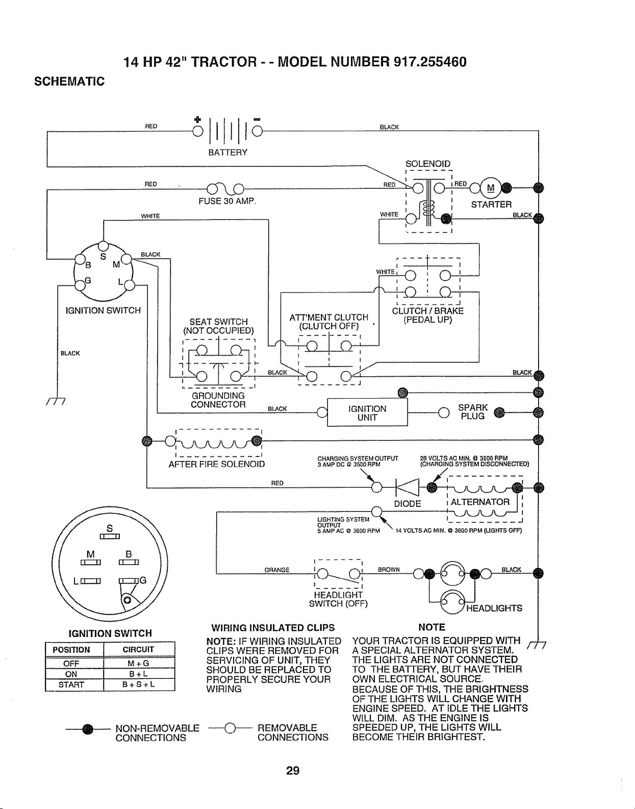
SCHEMATIC
14 HP 42" TRACTOR -- MODEL NUMBER 917.255460
i
/77
BATTERY
RED
WHITE
FUSE 30 AMP.,
SOLENOID
' r_ I1 STARTER
L(
IGNITION SWITCH
BLACK
SEAT SWITCH
(NOT OCCUPIED)
GROUNDING
CONNECTOR
! I
t _1
AFTER FIRE SOLENOID
ATT MENT CLUTCH I - -fPEDALUtS_ .....
J (CLUTCH OFF) " I '
t , : ;
_LA°*_0 0 _
BLACK 4_ IGNITIONUNIT
RED
BLACK
SPARK
PLUG
CHARGING SYSTEM otTrPUT 26 VOLTS AC MIN, @ 3600 RPM
3 AMP DC @ 3500 RPM (CHARGING SYSTEM DISCONNECTED)
_ DIODE _ALTERNATOR I i
UGHTING SYSTEM
output ._ .................
5 AMP AC @ 3600 RPM t4 VOLTS AC MIN,, @ 3600 RF'M {UGHTS OFF}
IGNITION SWITCH
f,osmoN c_Rcu,T
M+G
: OFF .........
ON B+L
START B+ S + L
NON-REMOVABLE
CONNECTIONS
ORANGE
I ...... I f'_
I ._ ,_ I BROWN _(__ BLACK A
! I
HEADLIGHT
SWITCH (OFF) k,,,.,j/' HEADLIGHTS
WIRING INSULATED CLIPS
NOTE: IF WIRING INSULATED
CLIPS WERE REMOVED FOR
SERVICING OF UNIT, THEY
SHOULD BE REPLACED TO
PROPERLY SECURE YOUR
WIRING
----(__z_ REMOVABLE
CONNECTIONS
D
D
NOTE
YOUR TRACTOR IS EQUIPPED WITH
A SPECIAL ALTERNATOR SYSTEM. /-2-/
THE LIGHTS ARE NOT CONNECTED
TO THE BATTERY, BUT HAVE THEIR
OWN ELECTRICAL SOU RCE_
BECAUSE OF THIS, THE BRIGHTNESS
OF THE LIGHTS WILL CHANGE WITH
ENGINE SPEED. AT IDLE THE LIGHTS
WILL DIM. AS THE ENGINE IS
SPEEDED UP, THE LIGHTS WILL
BECOME THEIR BRIGHTEST.
29
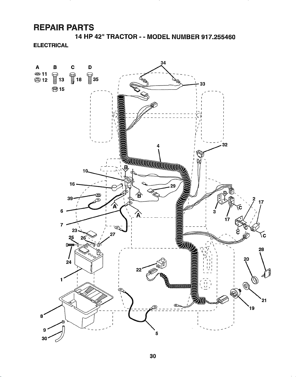
REPAIR PARTS
14 HP 42" TRACTOR - - MODEL NUMBER 917.255460
ELECTRICAL
34
4
33
/
I
8
27
! l
l
l
l
17
I
/ I
I
I
I
I
J
I
2O
19
2
17
28
21
3O
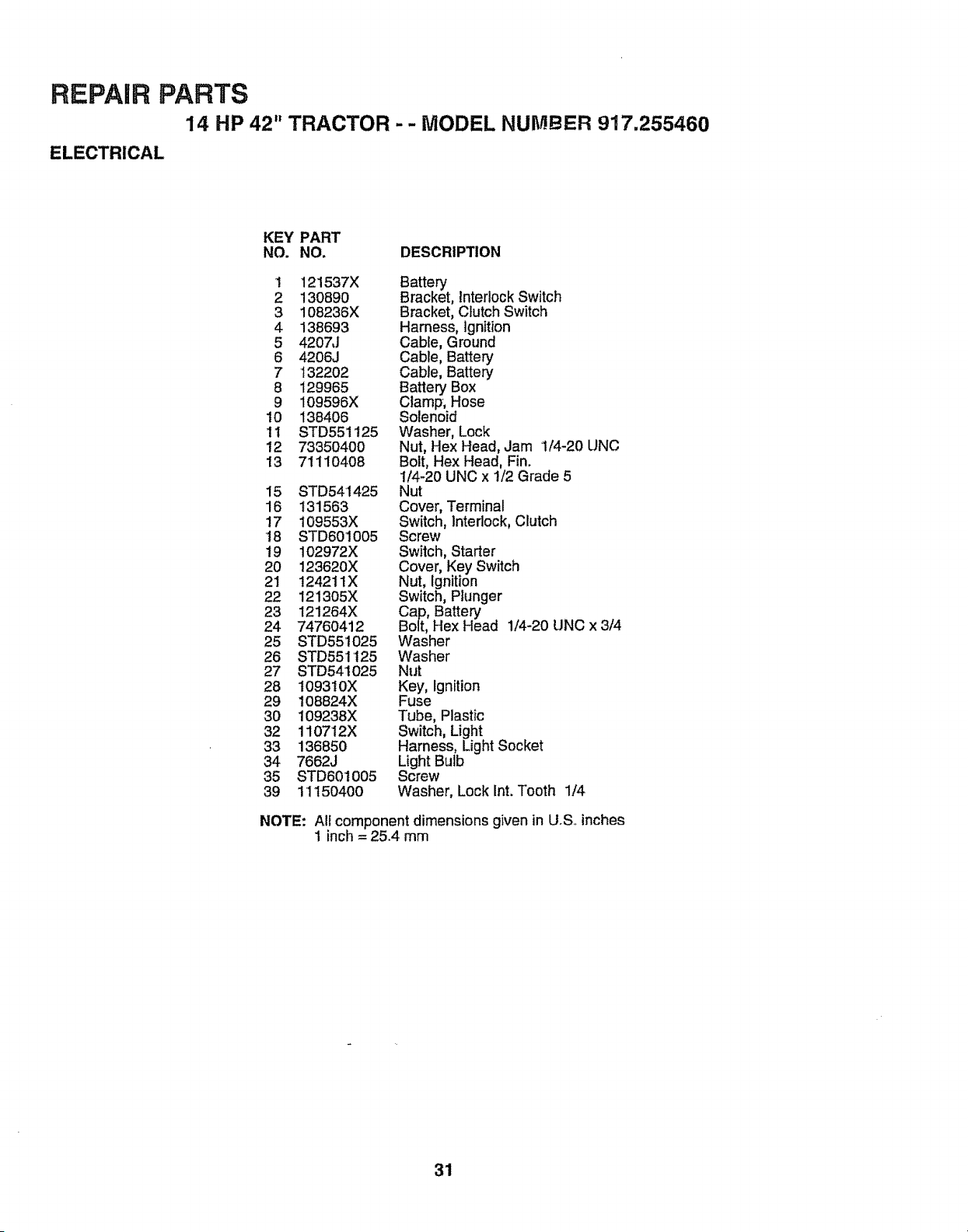
REPAIR PARTS
14 HP 42" TRACTOR - - MODEL NUMBER 917.255460
ELECTRICAL
KEY PART
NO. NO. DESCRIPTION
1 121537X
2 130890
3 108236X
4 138693
5 420_J
6 4206J
7 132202
8 129965
9 109596X
10 138406
11 STD551125
12 73350400
13 71110408
15 STD541425
16 131563
17 109553X
'!8 STD601005
19 102972X
20 123620X
21 124211X
22 t21305X
23 121264X
24 74760412
25 STD55!025
26 STD551125
27 STD541025
28 109310X
29 108824X
30 I09238X
32 110712X
33 136850
34 7662J
35 STD60t005
39 1I150400
Battenj
Bracket, Interlock Switch
Bracket, Crutch Switch
Harness, Ignition
Cable, Ground
Cable, Battery
Cable, Battery
Battery Box
Clamp; Hose
Solenoid
Washer, Lock
Nut, Hex Head, Jam 1/4-20 UNC
Bolt, Hex Head, Fin.
1/4-20 UNC x 1/2 Grade 5
Nut
Cover, Terminal
Switch, Interlock, Clutch
Screw
Switch, Starter
Cover, Key Switch
Nut, Ignition
Switch, Piunger
Cap, Battery
Bolt, Hex Head 1/4-20 UNC x 3/4
Washer
Washer
Nut
Key, Ignition
Fuse
Tube, Plastic
Switch, Light
Harness, Light Socket
Light Bulb
Screw
Washer, Lock Int. Tooth 1/4
NOTE: All component dimensions given in U°S,,inches
1 inch = 25.4 mm
31
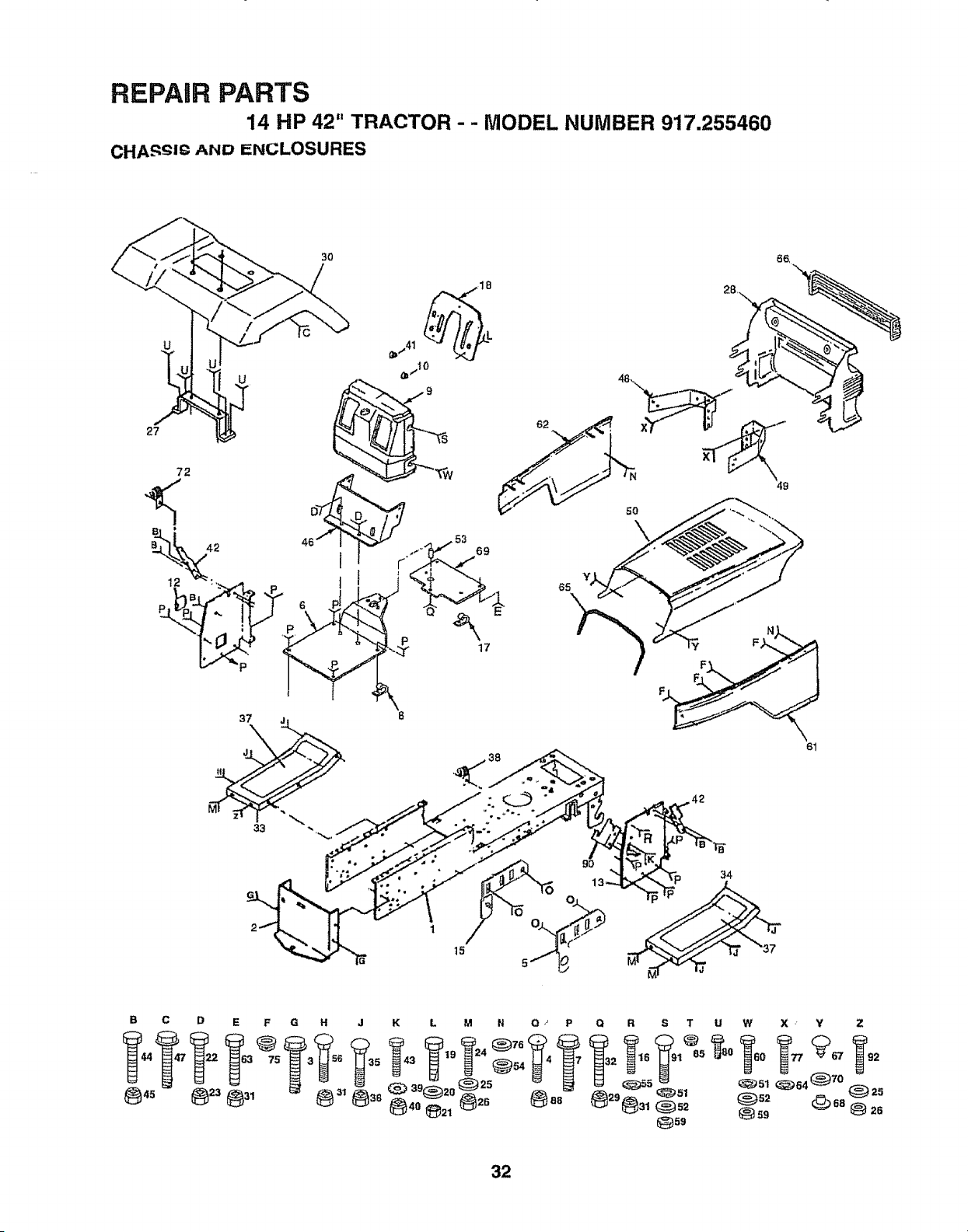
REPAIR PARTS
14 HP 42" TRACTOR - - MODEL NUMBER 917.255460
CHA_QJ¢ AND ENCLOSURES
30
65
5O
37 j_
tl
33
61
t5
34
B C D E F G H J K L M N O,' P
19 24 _76
O R S T U W X Y Z
32
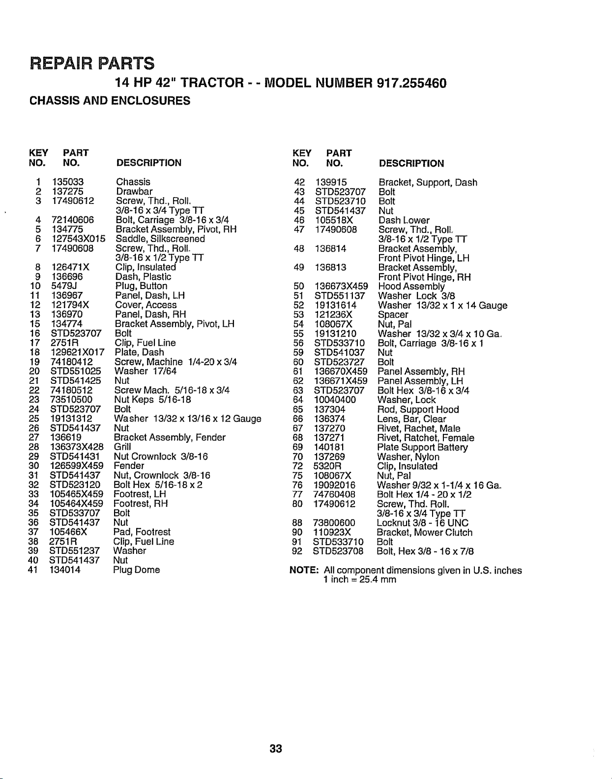
REPAIR PARTS
14 HP 42" TRACTOR - - MODEL NUMBER 917.255460
CHASSIS AND ENCLOSURES
KEY PART KEY PART
NO. NO. DESCRIPTION NO. NO, DESCRIPTION
1 135033 Chassis 42 1399t5 Bracket, Support, Dash
2 137275 Drawbar 43 STD523707 Bolt
3 17490612 Screw, Thd., Roll, 44 STD5237t0 Bolt
3/8-t6 x 3/4 Type TT 45 STD541437 Nut
4 72'140606 Bolt, Carriage 3/8-16 x 3/4 46 105518X Dash Lower
5 134775 Bracket Assembly, Pivot, RH 47 17490608 Screw, Thd., Roll.
6 127543X015 Saddle, Silkscreened 3/8-16 x 1/2 Type TT
7 17490608 Screw, Thd., Rollo 48 136814 Bracket Assembly,
3/8-16 x 1/2 Type TT Front Pivot Hinge, LH
8 126471X Clip, Insulated 49 136813 Bracket Assembly,
9 t36696 Dash, Plastic Front Pivot Hinge, RH
10 5479J Ptug, Button 50 136673X459 Hood Assembly
11 136967 Panel, Dash, LH 51 STD551137 Washer Lock 3/8
12 121794X Cover, Access 52 19131614 Washer 13/32 x I x 14 Gauge
13 136970 Panel, Dash, RH 53 121236X Spacer
15 134774 Bracket Assembly, Pivot, LH 54 108067X Nut, Pal
16 STD523707 Bolt 55 19131210 Washer 13/32 x 3/4 x 10 Ga.
17 2751R Clip, Fuel Line 56 STD533710 Bolt, Carriage 3/8-16 x 1
18 t29621X017 Plate, Dash 59 STD541037 Nut
19 74180412 Screw, Machine 1/4-20 x 3/4 60 STD523727 Bolt
20 STD551025 Washer 17/64 61 136670X459 Panel Assembly, RH
21 STD541425 Nut 62 136671X459 Panel Assembly, LH
22 74180512 Screw Mach. 5/16-18 x 3/4 63 STD523707 Bolt Hex 3/8-16 x 3t4
23 73510500 Nut Keps 5/16-18 64 10040400 Washer, Lock
24 STD523707 Bolt 65 !37304 Rod, Support Hood
25 19131312 Washer 13/32x 13/16x 12 Gauge 66 136374 Lens, Bar, Clear
26 STD541437 Nut 67 137270 Rivet, Rachet, Male
27 136619 Bracket Assembly, Fender 68 137271 Rivet, Ratchet, Female
28 136373X428 Grill 69 140181 Plate Support Battery
29 STD541431 Nut Crown!ock 3/8-16 70 137269 Washer, Nylon
30 126599X459 Fender 72 5320R Clip, Insulated
3t STD541437 Nut, Crownlock 3/8-16 75 108067X Nut, Pal
32 STD523120 Bolt Hex 5/16-18 x 2 76 19092016 Washer 9/32 x 1-1/4 x 16 Ga.
33 105465X459 Footrest, LH 77 74760408 Bolt Hex 1/4 - 20 x 1/2
34 105464X459 Footrest, RH 80 17490612 Screw, Thd. Roll.
35 STD533707 Bolt 3/8_16 x 3/4 Type "IF
36 STD541437 Nut 88 73800600 Locknut 3/8 - 16 UNC
37 105466X Pad, Footrest 90 !10923X Bracket, Mower Clutch
38 2751R Clip, Fuel Line 9t STD533710 Bolt
39 STD551237 Washer 92 STD523708 Bolt, Hex 3/8 - 16 x 7/8
40 STD541437 Nut
41 134014 Plug Dome NOTE: All component dimensions given in U.S. inches
1 inch = 25°4 mm
33
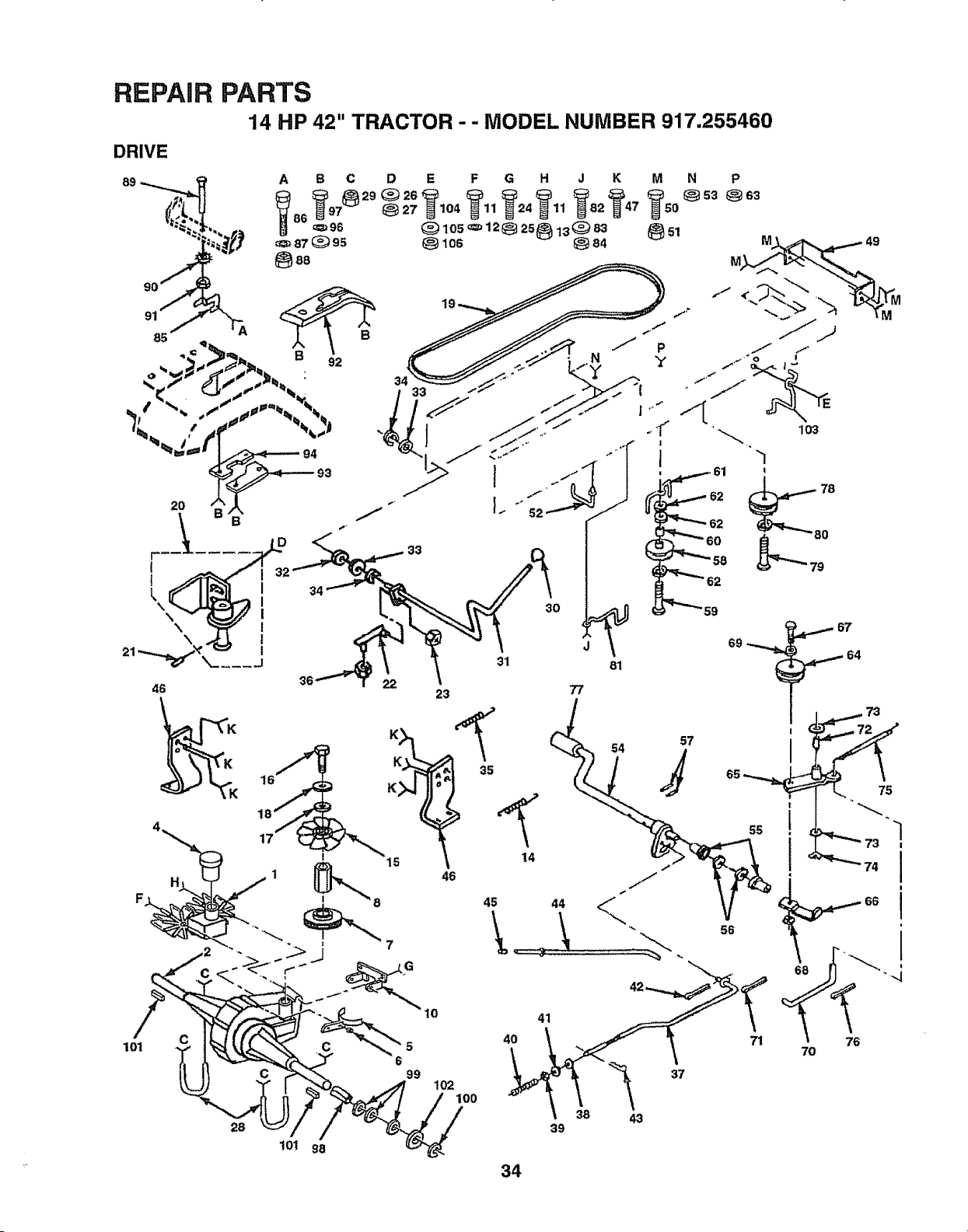
REPAIR
DRIVE
PARTS
14 HP 42" TRACTOR - - MODEL NUMBER 917.255460
21
85
\
\
\
46
i7
/
101
28
t01
34
1
1
33
30
31 81
36
23 77
K _ 54
35
1_"8 15 46
G
10
4O
6
99
102
100
41
f"
,_,, io3
'1
61 t
°
" " _ 58
57
37
55
56
71
1
I
I
/
7O
38 43
39
98
34
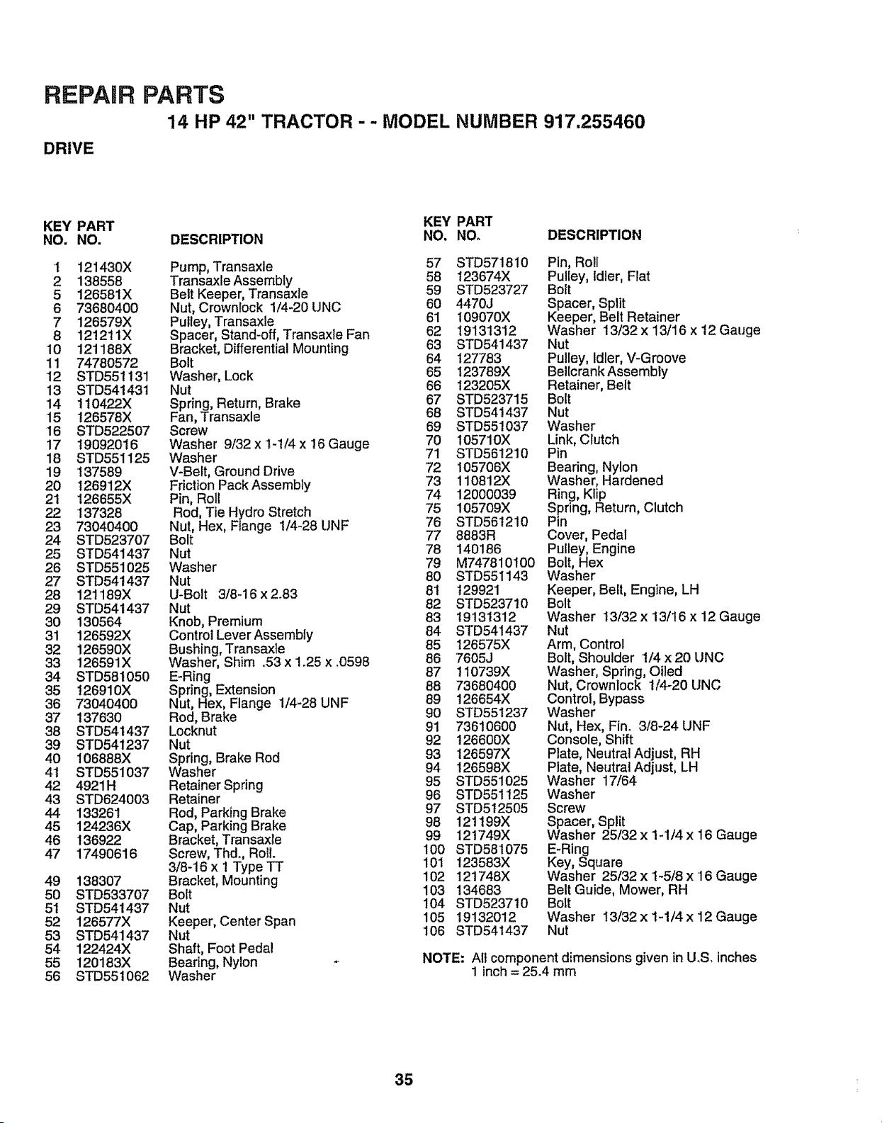
REPAIR PARTS
14 HP 42" TRACTOR - - MODEL NUMBER 917.255460
DRIVE
KEY PART KEY PART
NO. NO. DESCRIPTION NO. NOo DESCRIPTION
1 121430X Pump, Transaxle 57 STD571810
58 t23674X
2 138558 Transaxle Assembly
5 126581X Belt Keeper, Transaxie 59 STD523727
6 73680400 Nut, Crownlock 1/4-20 UNC 60 4470J
7 126579X Pulley, Transaxle 61 109070X
8 12!211X Spacer, Stand-off, Transaxle Fan 62 19131312
10 121188X Bracket, Differential Mounting 63 STD541437
11 74780572 Bolt 64 127783
12 STD551131 "Washer, Lock 65 I23789X
13 STD541431 Nut 66 I23205X
14 1t0422X Spring, Return, Brake 67 STD523715
15 126578X Fan, Transaxle 68 STD541437
16 STD522507 Screw 69 STD551037
17 19092016 Washer 9/32xl-1/4x 16 Gauge 70 105710X
18 STD551125 Washer 71 STD561210
19 137589 V-Belt, Ground Drive 72 105706X
20 t26912X Friction Pack Assembly 73 110812X
21 126655X Pin, Roll 74 12000039
22 137328 Rod, Tie Hydro Stretch 75 105709X
23 73040400 Nut, Hex, Flange i/4-28 UNF 76 STD561210
24 STD523707 Bolt 77 8883R
25 STD541437 Nut 78 140186
26 STD551025 Washer 79 M747810100
27 STD54t437 Nut 80 STD551143
28 121189X U-Bolt 3/8-16 x 2.83 81 129921
29 STD541437 Nut 82 STD523710
30 130564 Knob, Premium 83 19131312
31 126592X Control Lever Assembly 84 STD541437
32 126590X Bushing, Transaxle 85 126575X
33 126591X Washer, Shim .,53x 1.25 x .0598 86 7605J
34 STD581050 E-Ring 87 110739X
35 126910X Spring, Extension 88 73680400
36 73040400 Nut, Hex, Flange 1/4-28 UNF 89 126654X
37 t37630 Rod, Brake 90 STD551237
38 STD541437 Locknut 91 73610600
39 STD541237 Nut 92 126600X
40 106888X Spring, Brake Rod 93 126597X
4t STD551037 Washer 94 126598X
95 STD551025
42 4921H Retainer Spring
43 STD624003 Retainer 96 STD551!25
97 STD512505
44 133261 Rod, Parking Brake
45 124236X Cap, Parking Brake 98 121199X
46 I36922 Bracket, Transaxle 99 121749X
47 17490616 Screw, Thd., Roll. 100 STD581075
3/8-16 x 1 Type TT 101 t23583X
49 138307 Bracket, Mounting 102 121748X
50 STD533707 Bolt 103 134683
51 STD541437 Nut 104 STD523710
52 126577X Keeper, Center Span 105 19132012
53 STD541437 Nut 106 STD541437
54 122424X Shaft, Foot Pedal
55 120183X Bearing, Nylon
56 STD551062 Washer
Pin, Roll
Pulley, Idler, Fiat
Bolt
Spacer, Split
Keeper, Belt Retainer
Washer 13/32 x 13/16 x 12 Gauge
Nut
Pulley, Idler, V-Groove
Bellcrank Assembly
Retainer, Belt
Bolt
Nut
Washer
Link, Clutch
Pin
Bearing, Nylon
Washer, Hardened
Ring, Klip
Spring, Return, Clutch
Pin
Cover, Pedal
Pulley, Engine
Bolt, Hex
Washer
Keeper, Belt, Engine, LH
Bolt
Washer 13/32 x 13/16 x 12 Gauge
Nut
Arm, Control
Bolt, Shoulder 1/4 x 20 UNC
Washer, Spring, Oiled
Nut, Crownlock 1/4-20 UNC
Control, Bypass
Washer
Nut, Hex, Fin. 3/8-24 UNF
Console, Shift
Plate, Neutral Adjust, RH
Plate, Neutral Adjust, LH
Washer 17/64
Washer
Screw
Spacer, Split
Washer 25/32 x 1-1/4 x 16 Gauge
E-Ring
Key, Square
Washer 25/32 x 1-5/8 x 16 Gauge
Belt Guide, Mower, RH
Bolt
Washer 13/32 x 1-1/4 x 12 Gauge
Nut
NOTE: All component dimensions given in UoS. inches
1 inch = 25.4 mm
35
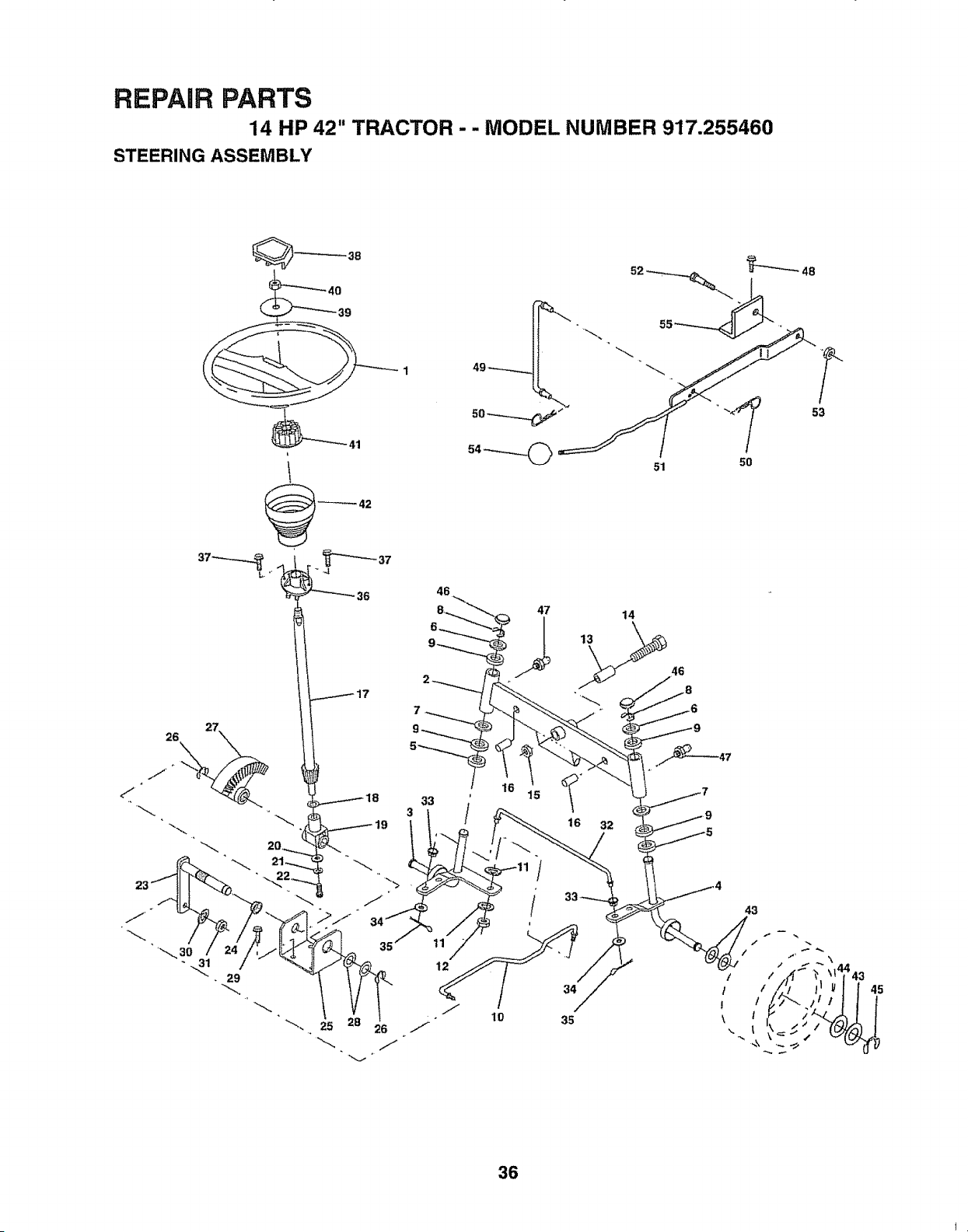
REPAIR PARTS
14 HP 42" TRACTOR .. - MODEL NUMBER 917.255460
STEERING ASSEMBLY
51
48
5O
53
46
7
47
/
/
!
lO
14
16 32
34
35
43
45
36
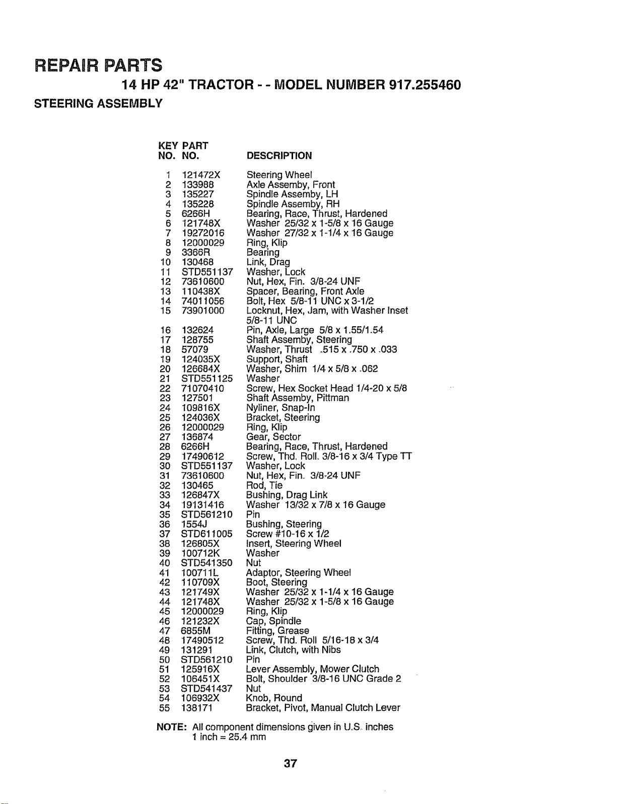
REPAIR PARTS
14 HP 42" TRACTOR - - MODEL NUMBER 9'17.255460
STEERING ASSEMBLY
KEY PART
NO. NO, DESCRIPTION
1 12t472X
2 133988
3 135227
4 135228
5 6266H
6 121748X
7 19272016
8 12000029
9 3366R
10 130468
1I STD551137
12 73610600
!3 110438X
14 74011056
15 73901000
16 132624
17 128755
18 57079
19 124035X
2O 126684X
21 STD551125
22 7t0704t0
23 127501
24 109816X
25 124036X
26 12000029
27 136874
28 6266H
29 17490612
3O STD55i137
31 73610600
32 130465
33 126847X
34 '19131416
35 STD561210
36 155&J
37 STD61t005
38 126805X
39 1007!2K
40 STD541350
41 100711L
42 !10709X
43 t21749X
44 121748X
45 12000029
46 121232X
47 6855M
48 17490512
49 131291
50 STD561210
51 125916X
52 106451X
53 STD541437
54 106932X
55 138171
Steering Wheel
Axle Assemby, Front
Spindle Assemby, LH
Spindle Assemby, RH
Bearing, Race, Thrust, Hardened
Washer 25/32 x I-5/8 x 16 Gauge
Washer 27/32 x t-1/4 x 16 Gauge
Ring, Klip
Bearing
Link, Drag
Washer, Lock
Nut, Hex, Fin. 3/8-24 UNF
Spacer, Bearing, Front Axle
Bolt, Hex 5/8-11 UNC x 34/2
Locknut, Hex, ,Jam, with Washer Inset
5/841 UNC
Pin, Axle, Large 518x 1..55/1.54
Shaft Assemby, Steering
Washer, Thrust o5!5 x .750 x _033
Support, Shaft
Washer, Shim 1/4 x 5/8 x .062
Washer
Screw, Hex Socket Head 1/4-20 x 5/8
Shaft Assemby, Pittman
Nyliner, Snap-In
Bracket, Steering
Ring, Klip
Gear, Sector
Bearing, Race, Thrust, Hardened
Screw, Thd. Ro& 3/8-16 x 3/4 Type TT
Washer, Lock
Nut, Hex, Fin.. 3/8-24 UNF
Rod, Tie
Bushing, Drag Link
Washer 13/32 x 7/8 x 16 Gauge
Pin
Bushing, Steering
Screw #10-16 x 1/2
Insert, Steering Wheel
Washer
Nut
Adaptor, Steering Wheel
Boot, Steering
Washer 25/32 x 1-1/4 x 16 Gauge
Washer 25/32 x 1-5/8 x 16 Gauge
Ring, Klip
Cap, Spindle
Fitting, Grease
Screw, Thd. Roll 5/16-18 x 3/4
Link, Clutch, with Nibs
Pin
Lever Assembly, Mower Clutch
Bolt, Shoulder 3/8-16 UNC Grade 2
Nut
Knob, Round
Bracket, Pivot, Manual Clutch Lever
NOTE: All component dimensions given in [J..S..inches
1 inch = 25.4 mm
37
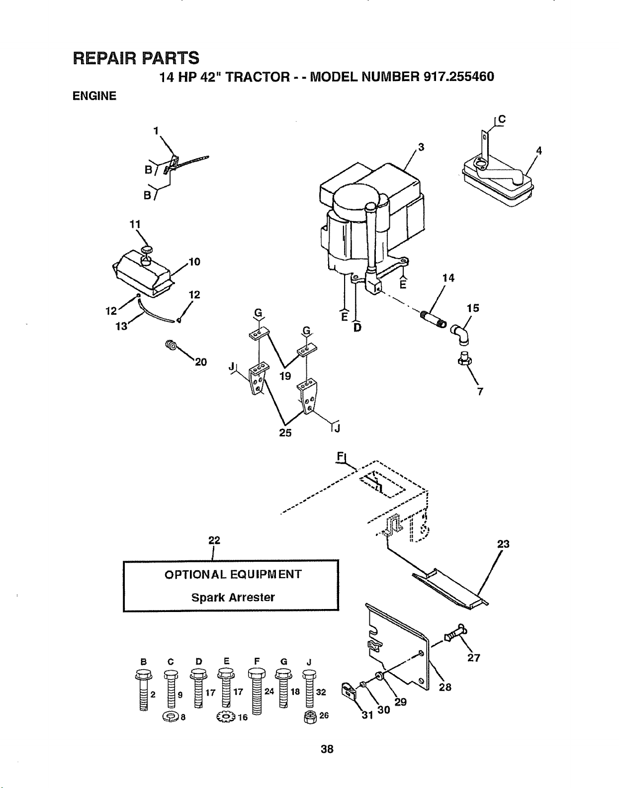
REPAIR PARTS
14 HP 42" TRACTOR -- MODEL NUMBER 917.255460
ENGINE
1
11
7
C
4
25
22
OPTIONAL EQUIPMENT
Spark Arrester
23
B C D E
C_8 _16
29
28
27
38
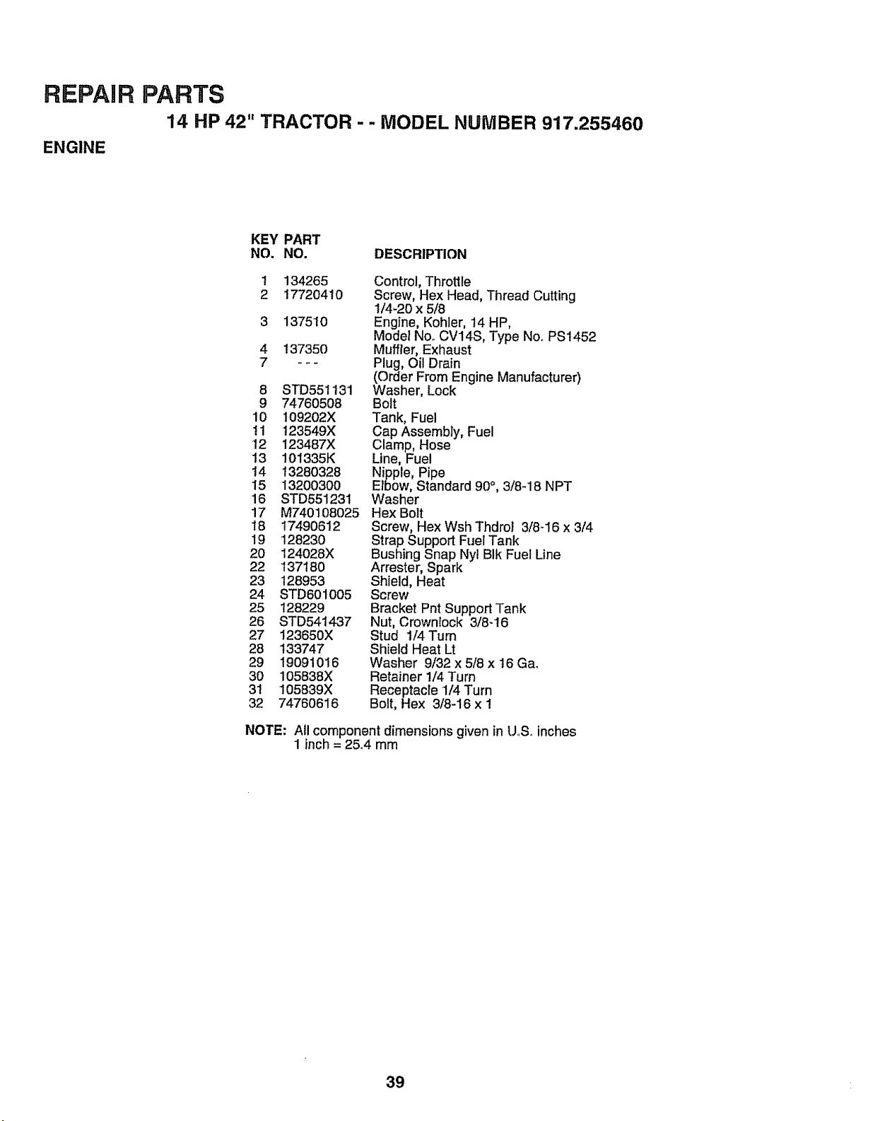
REPAIR PARTS
14 HP 42" TRACTOR - - MODEL NUMBER 917.255460
ENGINE
KEY PART
NO. NO. DESCRIPTION
t 134265 Control, Throttle
2 17720410 Screw, Hex Head, Thread Cutting
1/4-20 x 5/8
3 137510 Engine, Kohler, 14 HP,
Model No. CV14S, Type NooPS1452
4 137350 Muffler, Exhaust
7 - -- Plug, Oil Drain
(Order From Engine Manufacturer)
8 STD551t31 Washer, Lock
9 74760508 Bolt
10 109202X Tank, Fuel
ti 123549X Cap Assembly, Fuel
12 123487X Clamp, Hose
13 !01335K Line, Fuel
t4 13280328 Nipple, Pipe
15 13200300 Elbow, Standard 90°, 3/8-18 NPT
16 STD551231 Washer
17 M740108025 Hex Bolt
18 17490612 Screw, Hex Wsh Thdrol 3/8d6 x 3/4
19 '128230 Strap Support Fuel Tank
20 124028X Bushing Snap Nyl BIk Fuel Line
22 137!80 Arrester, Spark
23 128953 Shield, Heat
24 STD601005 Screw
25 128229 Bracket Pnt Support Tank
26 STD541437 Nut, Crownlock 3/8-16
27 123650X Stud I/4 Turn
28 133747 Shield Heat Lt
29 19091016 Washer 9/32 x 5/8 x 16 Ga.
30 105838X Retainer 1/4 Turn
3t 105839X Receptacle 1/4 Turn
32 74760616 Bolt, Hex 3/8-16 x I
NOTE: All component dimensions given in U,.Soinches
1 inch = 25.4 mm
39
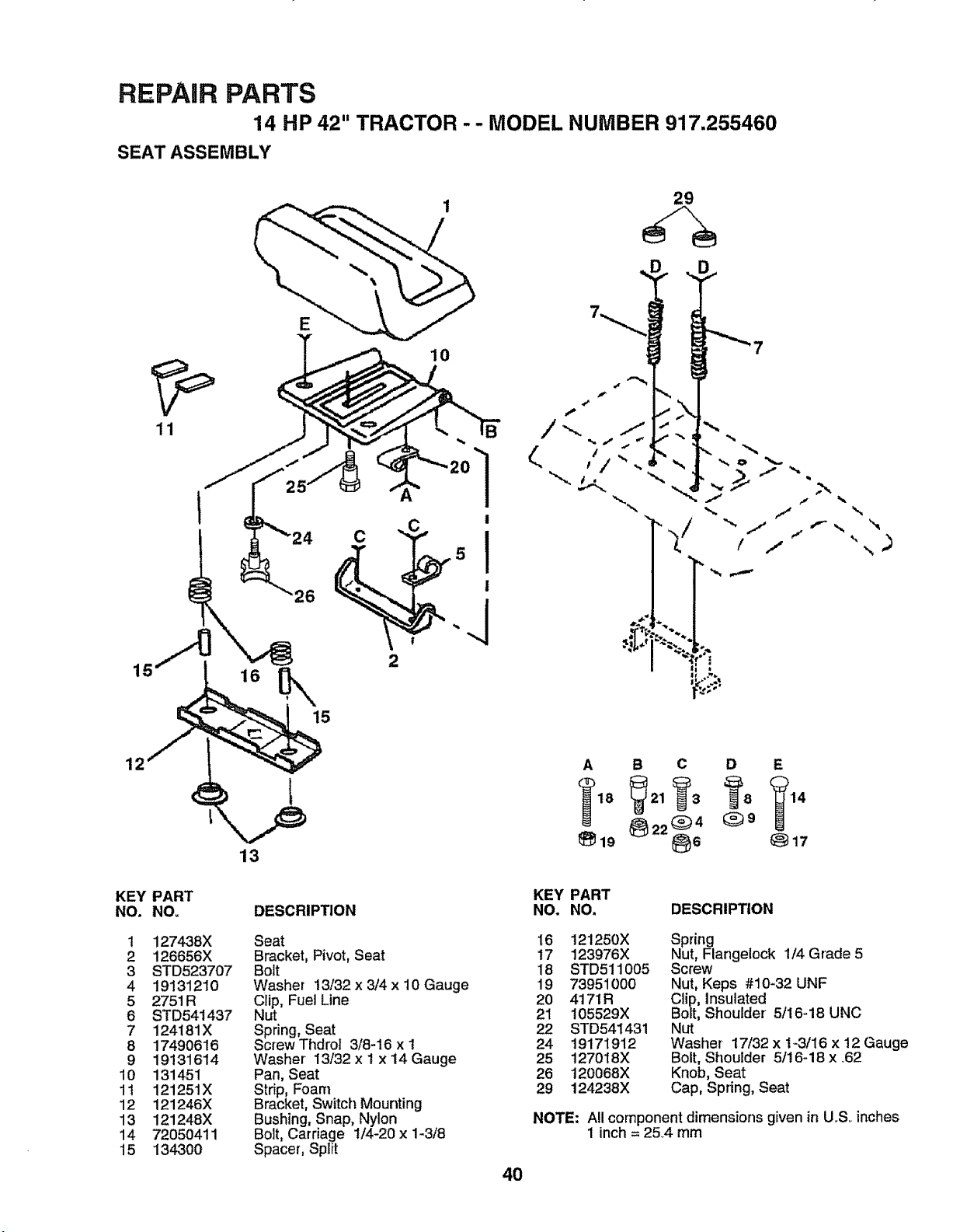
REPAIR PARTS
14 HP 42" TRACTOR - - MODEL NUMBER 917,255460
SEAT ASSEMBLY
29
11
26
15
O
10
B
1
!
I
!
.J
D D
"" _-. "" (,t"- >I _ "_
,t/ ---,
! ,i
,+I
i
I+ ,,,m,+
n,++ .._
', ,)
\
12
KEY
NO.
1
2
3
4
5
6
7
8
9
10
11
12
13
14
15
PART
NO_
1274,38X
126656X
8TD523707
19131210
2751 R
STD54t437
124181X
17490616
19131614
131451
121251X
121246X
121248X
72050411
134300
13
DESCRIPTION
Seat
Bracket, Pivot, Seat
Bolt
Washer 13/32 x 3/4 x 10 Gauge
Clip, Fuel Line
Nut
Spring, Seat
Screw Thdrol 3/8-16 x 1
Washer 13/32 x I x i4 Gauge
Pan, Seat
Strip, Foam
Bracket, Switch Mounting
Bushing, Snap, Nylon
Bolt, Carriage 1/4-20 x 1-3/8
Spacer, Spirt
4O
A B C D E
_19 +17
KEY PART
NO. NO, DESCRIPTION
16 121250X Spring
17 123976X Nut, Flangelock 1/4 Grade 5
18 STD511005 Screw
19 73951000 Nut, Keps #10+32 UNF
20 4171R Clip, Insulated
21 105529X Bolt, Shoulder 5/16-18 UNC
22 STD541431 Nut
24 19171912 Washer 17/32 x 1-3/16 x 12 Gauge
25 127018X Bolt, Shoulder 5/16-18 x +62
26 120068X Knob, Seat
29 124238X Cap, Spring, Seat
NOTE: All component dimensions given in U.S+ inches
1 inch = 25+4mm
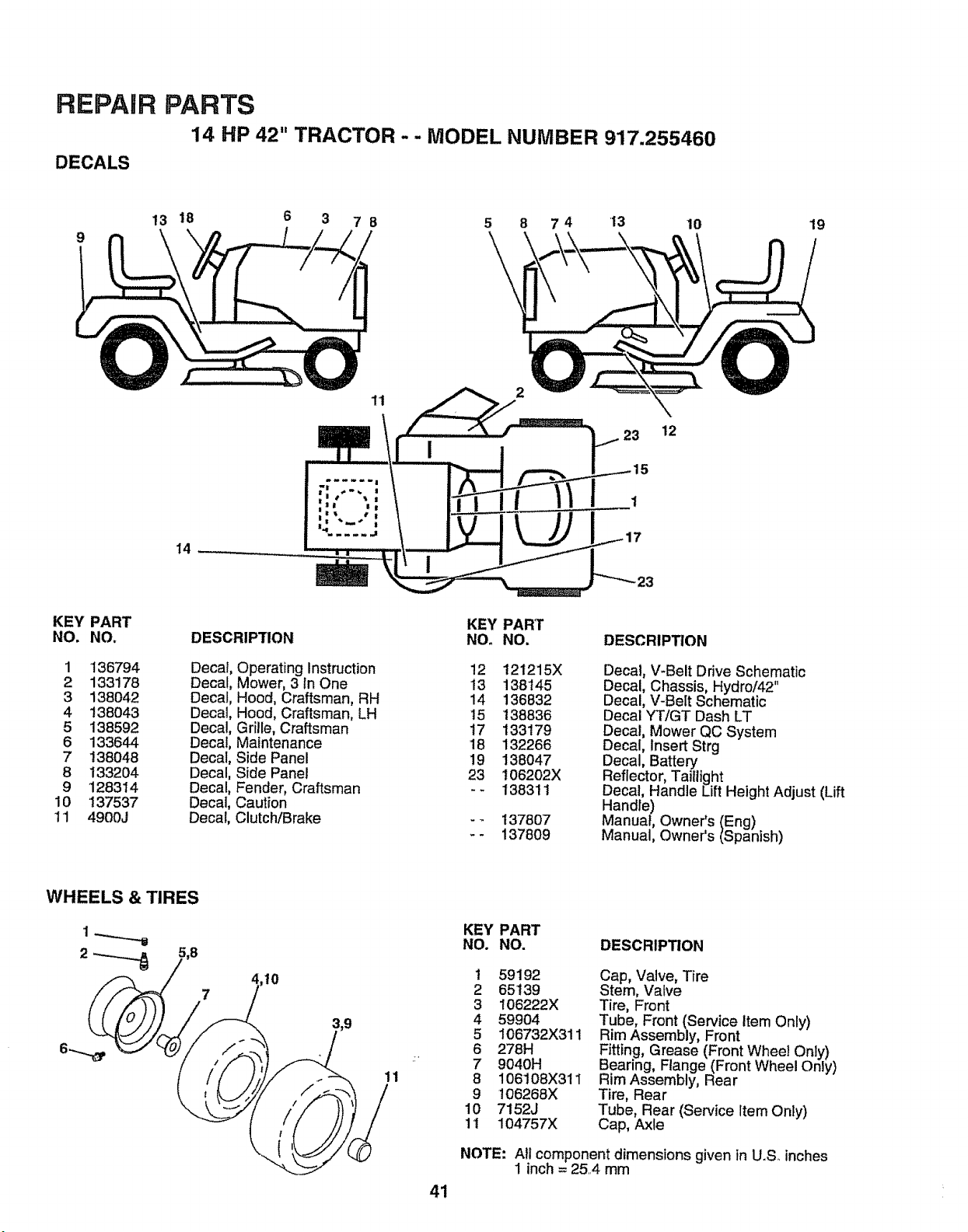
REPAIR
DECALS
PARTS
14 HP 42" TRACTOR - - MODEL NUMBER 917.255460
9
13 18 6 3 7 8 5 8 7 4 '13 10
19
14 -- ,
\
23 12
1
KEY
NO.
PART
NO,
1 136794
2 133178
3 138042
4 138043
5 138592
6 133644
7 138048
8 133204
9 128314
10 137537
11 4900J
DESCRIPTION
Decal, Operating Instruction
Decal, Mower, 3 In One
Decal, Hood, Craftsman, RH
Decal, Hood, Craftsman, LH
Decal, Grille, Craftsman
Decal, Maintenance
Decal, Side Panel
Decal, Side Panel
Decal, Fender, Craftsman
Decal, Caution
Decal, Clutch/Brake
KEY PART
NO. NO,
12 121215X
13 138145
14 136832
15 138836
17 133179
18 132266
19 138047
23 I06202X
-- 138311
137807
137809
DESCRIPTION
Decal, V-Belt Drive Schematic
Decal, Chassis, Hydro/42"
Decal, V-Belt Schematic
Decal YT/GT Dash LT
Decal, Mower QC System
Decal, Insert Strg
Decal, Battery
Reflector, Taillight
Decal, Handle Lift Height Adjust (Lift
Handle)
Manual, Owner's (Eng)
Manual, Owner's (Spanish)
WHEELS & TIRES
7
10
11
41
KEY PART
NO. NO.
DESCRIPTION
1 59192
2 65139
3 106222X
4 59904
5 106732X311
6 278H
7 9040H
8 106108X311
9 106268X
10 7152J
11 104757X
Cap, Valve, Tire
Stem, Valve
Tire, Front
Tube, Front (Service Item Only)
Rim Assembly, Front
Fitting, Grease (Front Whee! Only)
Bearing, Flange (Front Wheel Only)
Rim Assembly, Rear
Tire, Rear
Tube, Rear (Service Item Only)
Cap, Axle
NOTE: All component dimensions given in U.S inches
1 inch = 25..4 mm
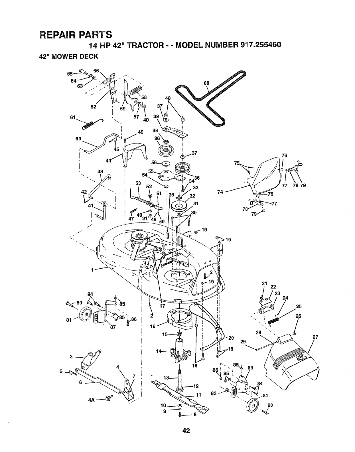
REPAIR PARTS
14 HP 42" TRACTOR - - MODEL NUMBER 917.255460
42" MOWER DECK
63
62
4O
57
68
74
21
22
28
29
76
77 78 79
24
25
26
l
27
42
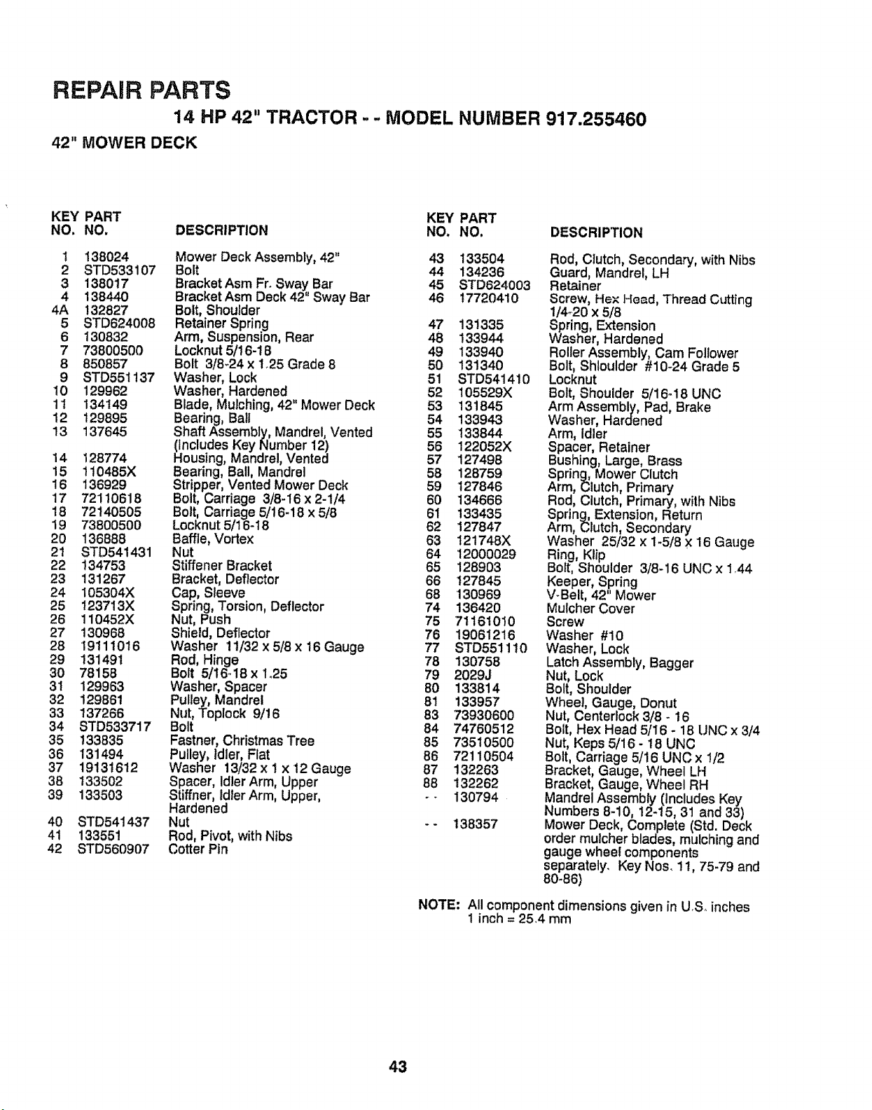
REPAIR PARTS
14 HP 42" TRACTOR - - MODEL NUMBER 917.255460
42" MOWER DECK
KEY PART KEY PART
NO. NO. DESCRIPTION NO. NO. DESCRIPTION
1 138024 Mower Deck Assembly, 42" 43 133504
2 STD533107 Bolt 44 134236
3 1380t7 Bracket Asm Fr_Sway Bar 45 STD624003
4 138440 Bracket Asm Deck 42" Sway Bar 46 17720410
4A 132827 Bolt, Shoulder
5 STD624008 Retainer Spring 47 13!335
6 130832 Arm, Suspension, Rear 48 133944
7 73800500 Locknut 5/16-18 49 133940
8 850857 Bolt 3/8-24 x 1.25 Grade 8 50 131340
9 STD551137 Washer, Lock 51 STD541410
10 129962 VVasher, Hardened 52 105529X
11 134149 Blade, Mulching, 42"Mower Deck 53 131845
12 t29895 Bearing, Ball 54 133943
13 137645 Shaft Assembly, Mandrel, Vented 55 !33844
(Includes KeyNumber 12) 56 122052X
14 128774 Housing, Mandrel, Vented 57 127498
15 110485X Bearing, Bail, Mandrel 58 128759
16 !36929 Stripper, Vented Mower Deck 59 t27846
17 72110618 Bolt, Carriage 3/8-16x 2-1/4 60 134666
18 72140505 Bolt, Carriage 5/16-18 x5/8 61 133435
19 73800500 Locknut 5/!6-18 62 127847
20 136888 Baffle, Vortex 63 t21748X
21 STD541431 Nut 64 12000029
22 134753 Stiffener Bracket 65 128903
23 131267 Bracket, Deflector 66 t27845
24 105304X Cap, Sleeve 68 130969
25 123713X Spring, Torsion, Deflector 74 136420
26 110452X Nut, Push 75 71161010
27 130968 Shield, Deflector 76 19061216
28 19111016 Washer 11/32 x5/Sx 16 Gauge 77 STD551110
29 131491 Rod, Hinge 78 130758
30 78158 Bolt 5/16_18x Io25 79 2029J
31 129963 Washer, Spacer 80 133814
32 129861 Pulley, Mandrel 81 133957
33 137266 Nut, Toplock 9/!6 83 73930600
34 STD533717 Bolt 84 74760512
35 133835 Fastner, Christmas Tree 85 73510500
36 131494 Pulley, Idler, Flat 86 72110504
37 19131612 Washer 13/32x 1 x 12 Gauge 87 132263
38 133502 Spacer, Idler Arm, Upper 88 132262
39 133503 Stiffner, Idler Arm, Upper, - - 130794
Hardened
40 STD541437 Nut -- 138357
41 133551 Rod, Pivot, with Nibs
42 STD560907 Cotter Pin
Rod, Clutch, Secondary, with Nibs
Guard, Mandrel, LH
Retainer
Screw, He× He_d, Thread Cutting
1/4_20 x 5/8
Spring, Extension
Washer, Hardened
Roller Assembly, Cam Follower
Bolt, Shloulder #10-24 Grade 5
Locknut
Bolt, Shoulder 5/16_18 UNC
Arm Assembly, Pad, Brake
Washer, Hardened
Arm, Idler
Spacer, Retainer
Bushing, Large, Brass
Spring, Mower Clutch
Arm, Clutch, Primary
Rod, Clutch, Primary, with Nibs
Spring, Extension, Return
Arm, Clutch, Secondary
Washer 25/32 x 1-5/8 X '16 Gauge
Ring, Klip
Bolt, Shoulder 3/'8-16 UNC x 1.44
Keeper, Spring
V-Belt, 42" Mower
Mulcher Cover
Screw
Washer #10
Washer, Lock
Latch Assembly, Bagger
Nut, Lock
Bolt, Shoulder
Wheel, Gauge, Donut
Nut, Centeriock 3/8 - 16
Bolt, Hex Head 5/16 - 18 UNC x 3/4
Nut, Keps 5/16 - t8 UNC
Bolt, Carriage 5/16 UNC x 1/2
Bracket, Gauge, Wheel LH
Bracket, Gauge, Wheel RH
Mandrel Assembly (includes Key
Numbers 8-10, 12.15, 31 and 33)
Mower Deck, Complete (Std. Deck
order mulcher blades, mulching and
gauge wheel components
separately. Key Nos. 11, 75-79 and
80-86)
NOTE: All component dimensions given in US_ inches
1 inch = 25.4 mm
43
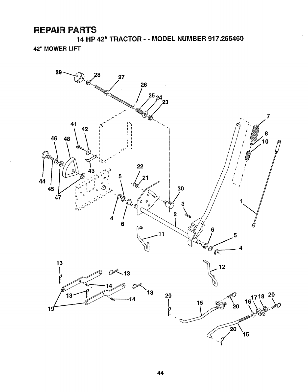
REPAIR PARTS
14 HP 42" TRACTOR-- MODEL NUMBER 917.255460
42" MOWER LIFT
28
27
26
44
46 48
45
47
13
24
23
43
4
6
"%-----14
13
20
6
15
20
161718
20
44
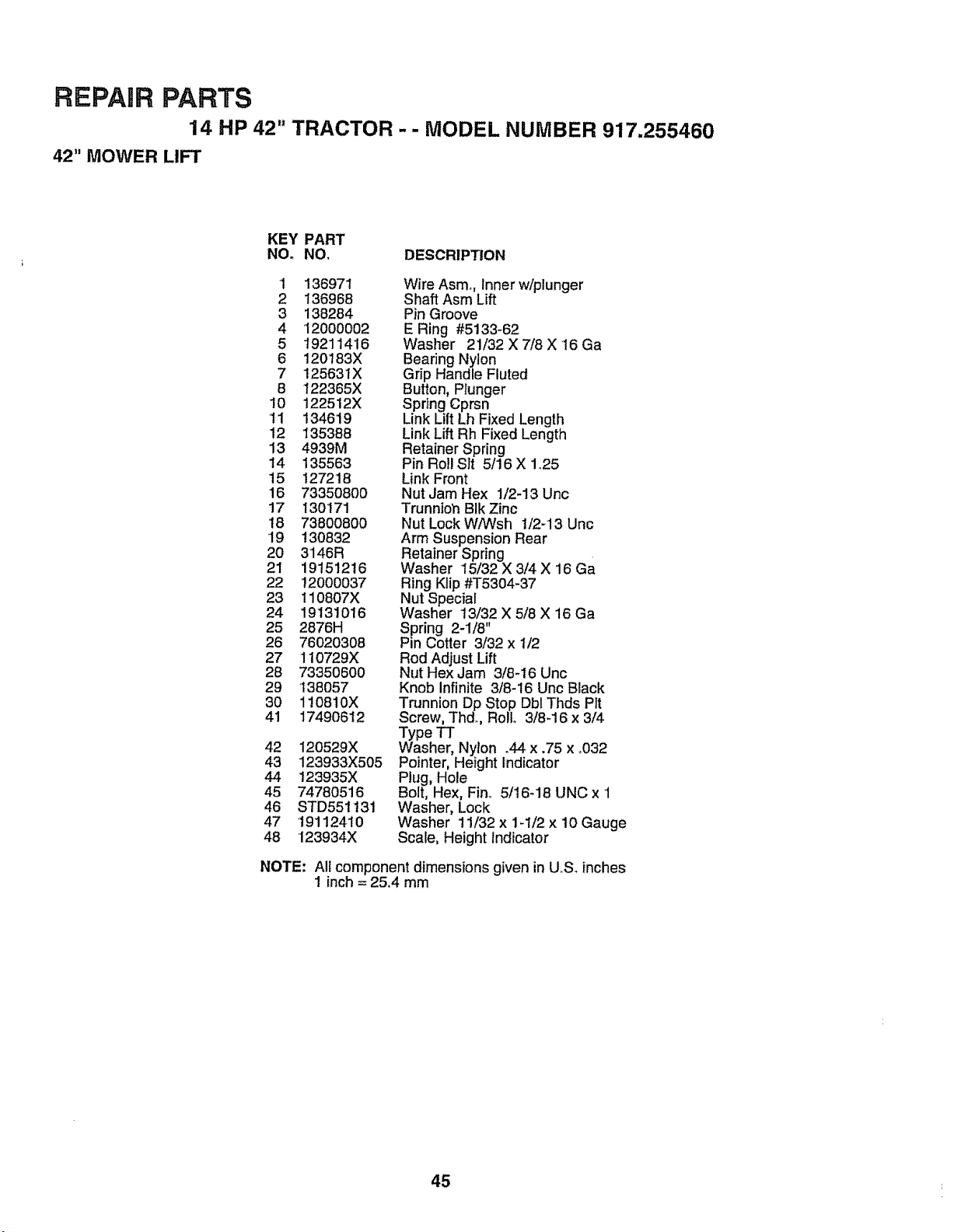
REPAIR PARTS
14 HP 42" TRACTOR - - MODEL NUMBER 917.255460
42" MOWER LIFT
KEY PART
NO. NO, DESCRIPTION
1 136971
2 136968
3 138284
4 12000002
5 19211416
6 120183X
7 125631X
6 122365X
10 122512X
11 134619
12 135388
13 4939M
14 135563
15 127218
16 73350800
17 130171
18 738OO800
"19 130832
20 3146R
21 19151216
22 '12000037
23 110807X
24 19131016
25 2876H
26 76020308
27 110729X
28 73350600
29 138057
30 110810X
41 17490612
42 120529X
43 123933X505
44 123935X
45 74780516
46 STD551t3i
47 19112410
48 123934X
Wire Asmo, Inner w/plunger
Shaft Asm Lift
Pin Groove
E Ring #5133_62
Washer 21/32 X 7/8 X 16 Ga
Bearing Nylon
Grip Handle Fluted
Button, Plunger
Spring Cprsn
Link Lift Lh Fixed Length
Link Lift Rh Fixed Length
Retainer Spring
Pin Rol! Sit 5/16 X 1_25
Link Front
Nut Jam Hex 1/2-13 Unc
Trunnioh BIk Zinc
Nut Lock W/Wsh t/2-13 Unc
Arm Suspension Rear
Retainer Spring
Washer 15/32 X 3/4 X 16 Ga
Ring Klip #T5304-37
Nut Special
Washer 13/32 X 5/8 X 16 Ga
Spring 2-1/8"
Pin Cotter 3/32 x 1/2
Rod Adjust Lift
Nut Hex Jam 3/8-16 Unc
Knob Infinite 3/8-i6 Unc Black
Trunnion Dp Stop Dbl Thds Pit
Screw, Thd., Roll 3/8-16 x 3/4
Type TT
Washer, Nylon .44 x .75 x °032
Pointer, Height indicator
Plug, Hole
Bolt, Hex, Fin° 5/16-18 UNC x '1
Washer, Lock
Washer 11/32 x 1-1/2 x 10 Gauge
Scale, Height hdicator
NOTE: All component dimensions given in UoS.inches
1 inch = 25.4 mm
45
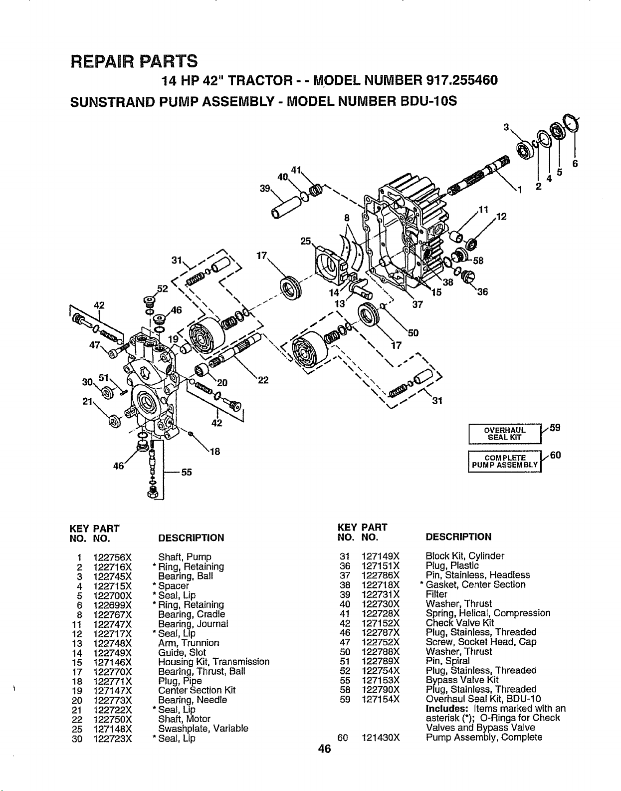
REPAIR PARTS
14 HP 42" TRACTOR-- MODEL NUMBER 917.255460
SUNSTRAND PUMP ASSEMBLY - MODEL NUMBER BDU-10S
3\
42
30,
21\
42
18
4O
>
25
-" 37
5
I 2
OVERHAUL ]F59
SEAL KIT
COMPLETE 1t,60
PUMP ASSEMBLY]
6
KEY
NO.
1
2
3
4
5
6
8
11
12
13
14
15
17
18
19
20
21
22
25
30
PART
NO.
122756X
122716X
122745X
122715X
t22700X
122699X
122767X
122747X
122717X
122748X
122749X
t 27 ! 46X
t 22770X
122771X
127147X
122773X
122722X
t22750X
127148X
122723X
DESCRIPTION
Shaft, Pump
* Ring, Retaining
Bearing, Ball
* Spacer
* Seal, Lip
* Ring, Retaining
Bearing, Cradle
Bearing, Journal
* Seal, Lip
Am1, Trunnion
Guide, Slot
HousingKit, Transmission
Bearing,Thrust, Ball
Plug, Pipe
Center Section Kit
Beadng, Needle
* Seal, Lip
Shaft, Motor'
Swashplate, Variable
* Seal, Lip
KEY PART
NO. NO.
31 127149X
36 127151X
37 122786X
38 122718X
39 122731X
4O 122730X
4! 122728X
42 127152X
46 t22787X
47 122752X
50 122788X
51 122789X
52 122754X
55 127153X
58 122790X
59 127154X
6O
46
12t430X
DESCRIPTION
Block Kit, Cylinder
Ptug, Plastic
Pin, Stainless, Headless
Gasket, Center Section
Filter
Washer, Thrust
Spdng, Helical, Compression
Check Valve Kit
Plug, Stainless, Threaded
Screw, Socket Head, Cap
Washer, Thrust
Pin, Spiral
Plug, Stainless, Threaded
Bypass Valve Kit
Plug, Stainless, Threaded
Overhaul Seal Kit, BDU-10
Includes: Items marked with an
asterisk (*); O-Rings for Check
Valves and Bypass Valve
Pump Assembly, Complete
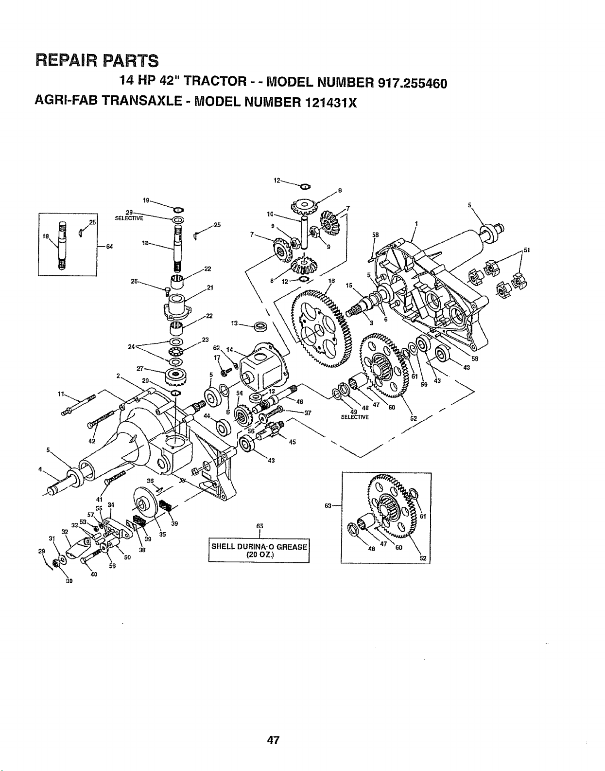
REPAIR PARTS
14 HP 42" TRACTOR -- MODEL NUMBER 917.255460
AGRI-FAB TRANSAXLE - MODEL NUMBER 121431X
I
58
43
51
42
i SHELL
45
6S
r
DURINA-O GREASE 1(20 OZ.)
48
47 ,
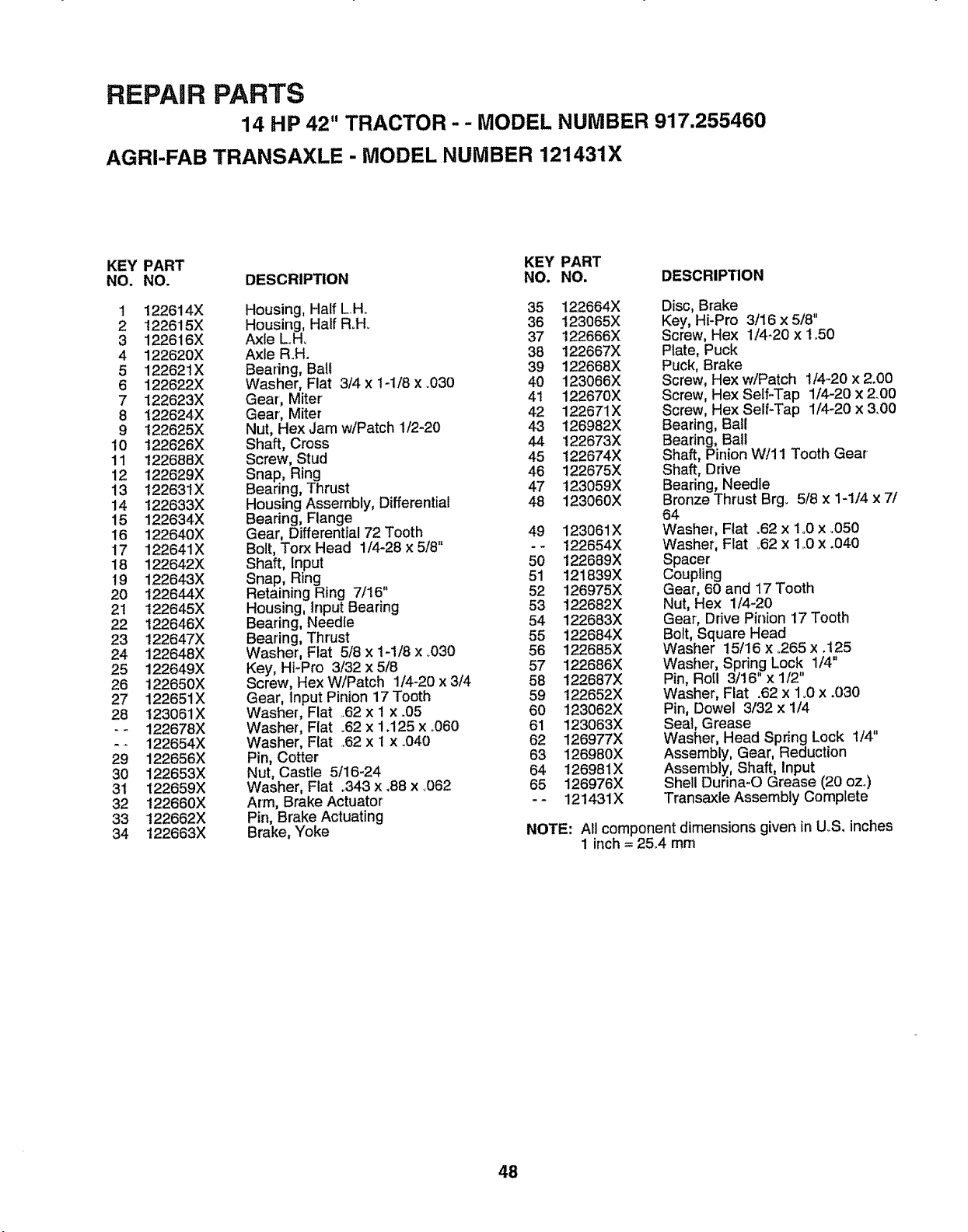
REPAIR PARTS
14 HP 42" TRACTOR - - MODEL NUMBER 917,255460
AGRI-FAB TRANSAXLE - MODEL NUMBER 121431X
KEY PART KEY PART
NO. NO. DESCRIPTION NO. NO. DESCRIPTION
1 122614X
2 122615X
3 1226!6X
4 122620X
5 122621X
6 122622X
7 122623X
8 122624X
9 122625X
10 t22626X
11 t22688X
12 122629X
13 122631X
14 t22633X
15 122634X
16 122640X
17 122641X
18 122642X
19 122643X
20 122644X
2t 122645X
22 122646X
23 122647X
24 122648X
25 122649X
26 122650X
27 122651X
28 123061X
-- 122678X
-- 122654X
29 122656X
30 122653X
31 122659X
32 122660X
33 122662X
34 122663X
Housing, Half L H. 35
Housing, Half Roll. 36
Axle Loll. 37
Axle R.H. 38
Bearing, Ball 39
Washer, Fiat 3/4 x 1-1/8 x .030 40
Gear, Miter 41
Gear, Miter 42
Nut, Hex Jam w/Patch 1/2-20 43
Shaft, Cross 44
Screw, Stud 45
Snap, Ring 46
Bearing, Thrust 47
Housing Assembly, Differential 48
Bearing, Flange
Gear, Differential 72 Tooth 49
Bolt, Torx Head 1/4-28 x 5/8" - -
Shaft, Input 50
Snap, Ring 51
Retaining Ring 7/16" 52
Housing, Input Bearing 53
Bearing, Needle 54
Bearing, Thrust 55
Washer, Flat 5/8 x 1-1/8 x .030 56
Key, Hi-Pro 3/32 x 5/8 57
Screw, Hex W/Patch 1/4-20 x 3/4 58
Gear, Input Pinion 17 Tooth 59
Washer, Flat .62 x I x .05 60
Washer, Fiat .62 x 1,125 x °060 61
Washer, Fiat .62 x 1 x .040 62
Pin, Cotter 63
Nut, Castle 5/16-24 64
Washer, Fiat .343 x ,88 x .062 65
Arm, Brake Actuator - -
Pin, Brake Actuating
Brake, Yoke
122664X
123065X
122666X
122667X
122668X
123066X
122670X
122671X
126982X
122673X
122674X
122675X
123059X
123060X
123061X
122654X
122689X
121839X
126975X
122682X
122683X
122684X
122685X
122686X
122687X
122652X
123062X
123063X
126977X
126980X
126981X
126976X
121431X
Disc, Brake
Key, Hi-Pro 3/16 x 5/8"
Screw, Hex 1/4-20 x 1°50
Plate, Puck
Puck, Brake
Screw, Hex w!Patch 1/4-20 x 2.00
Screw, Hex Self-Tap 1/4-20 x 2.00
Screw, Hex Self-Tap 1t4-20 x 3.00
Bearing, Ball
Bearing, Ball
Shaft, Pinion W!11 Tooth Gear
Shaft, Ddve
Bearing, Needle
Bronze Thrust Brg. 5/8 x 1-1/4 x 7/
64
Washer, Flat .62 x 1..0x °050
Washer, Fiat .62 x 1..0x .040
Spacer
Coupling
Gear, 60 and 17 Tooth
Nut, Hex 1/4-20
Gear, Drive Pinion 17 Tooth
Bolt, Square Head
Washer 15/16 x .265 x .125
Washer, Sprin,g Lock, 1/4"
Pin, Ro[I 3/16 x 1/2
Washer, Flat .62 x 1.0 x .030
Pin, Dowel 3/32 x 1/4
Seal, Grease
Washer, Head Spring Lock 1/4"
Assembly, Gear, Reduction
Assembly, Shaft, Input
Shell Durina-O Grease (20 oz.)
Transaxle Assembly Complete
NOTE: All compor]ent dimensions given in U,S, inches
1 inch = 25.4 mm
48
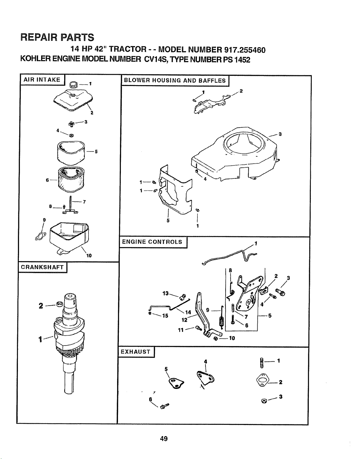
REPAIR PARTS
14 HP 42" TRACTOR - - MODEL NUMBER 917.255460
KOHLER ENGINE MODEL NUMBER CV14S, TYPE NUMBER PS 1452
AIRiNT K'E'"}"0--'
9
10
BLOWER HOUSING AND BAFFLES I
1
ENGINE CONTROLS,,,,,,,i
• ,-.,....15
11
EXHAUSTi ....
.r
6
4
2 3
/
2
49

REPAIR PARTS
14 HP 42" TRACTOR -- MODEL NUMBER 917.255460
KOHLER ENGINE MODEL NUMBER CV14S, TYPE NUMBER PS 1452
AIR INTAKE
BL()WER HOUSING AND BAFFLES
KEY PART KEY PART
NO. NO. DESCRIPTION NOo NO. DESCRIPTION
t 12 341 01 Knob, Air Cleaner Cover
2 t2 096 06 Cover', Air-Cleaner -.
3 12 100 01 Wing Nut
4 X-25-63 Washer, Plain 1/4
5 12 083 08 Precleaner Element
6 12 083 05 Element, Air'Cleaner
7 12 072 03 Stud, Mounting Plate
8 12 086 01 Screw, Mounting Plate Stud
9 12 041 02 Gasket, Air' Cleaner
t0 12 094 01 Base, Air Cleaner
NOT ILLUSTRATED
- * 12 113 27 Decal, Air Cleaner
EXHAUST
KEY PART
NO. NO. DESCRIPTION
1 M-0829033
2 12 041 03
3 M-0841080
4 12 126 11
5 12445 01
6 M-0645025
Stud, Exhaust Manifold
M8 x 1.25 x 20 (2)
Gasket, Exhaust Manifold
Nut, Muffler Mounting M8 x 1.25 (2)
Bracket, Muffler
Strap, Lifting
Screw, Lifting Strap
M6 x 1.0 x 25 (2)
Short Block
Gasket Set
-- 12 522 01
-- 12 755 01
DESCRIPTION
Crankshaft
Plug, Cup
CRANKSHAFT
KEY PART
NO. NO.
1 1201402
2 12139O1
1
2
3
4
5
SM-0545010
12 146 O7
12 027 14
12 313 03
12 063 08
Screw, Mounting M5 x 0.8 x 10 (t2)
Plate, Blower Housing
Housing, Blower
Grommet, Blower Housing
Baffle, Cylinder Head
NOT ILLUSTRATED
-- 12 113 28 Decal, Horsepower
ENGINE CONTROLS
KEY PART
NO, NO.
DESCRIPTION
1
2
3
4
5
12 079 07
12 237 01
SM-0645016
SM-0545016
12 536 01
6 SM-0443025
7 12O89 11
8 12089 04
9 12 089 19
t0 SM*0641060
11 SM-0642025
12 12 090 05
13 25 158 11
14 12 079 01
15 25 158 08
Linkage, Choke
Clamp, Cable
Screw, Hex Head M6 x 1_0x 16 (2)
Screw, Cable Clamp
Control, Speed Assembly (Includes
Key Numbers 6 through 8)
Screw
Spring, Choke Adjust
Spring, Choke Return
Spring, Governor
Nut, Governor' Arm M6 x 1.0
Screw, Governor Arm
M6 x 1.0 x 25
Lever, Governor
Bushing
Linkage, Throttle
Bushing
NOTE: All component dimensions given in U.Soinches
1 inch = 25_4 mm
RPM Settings: Low Speed I500.2000
High Speed 3200- 3400
5O
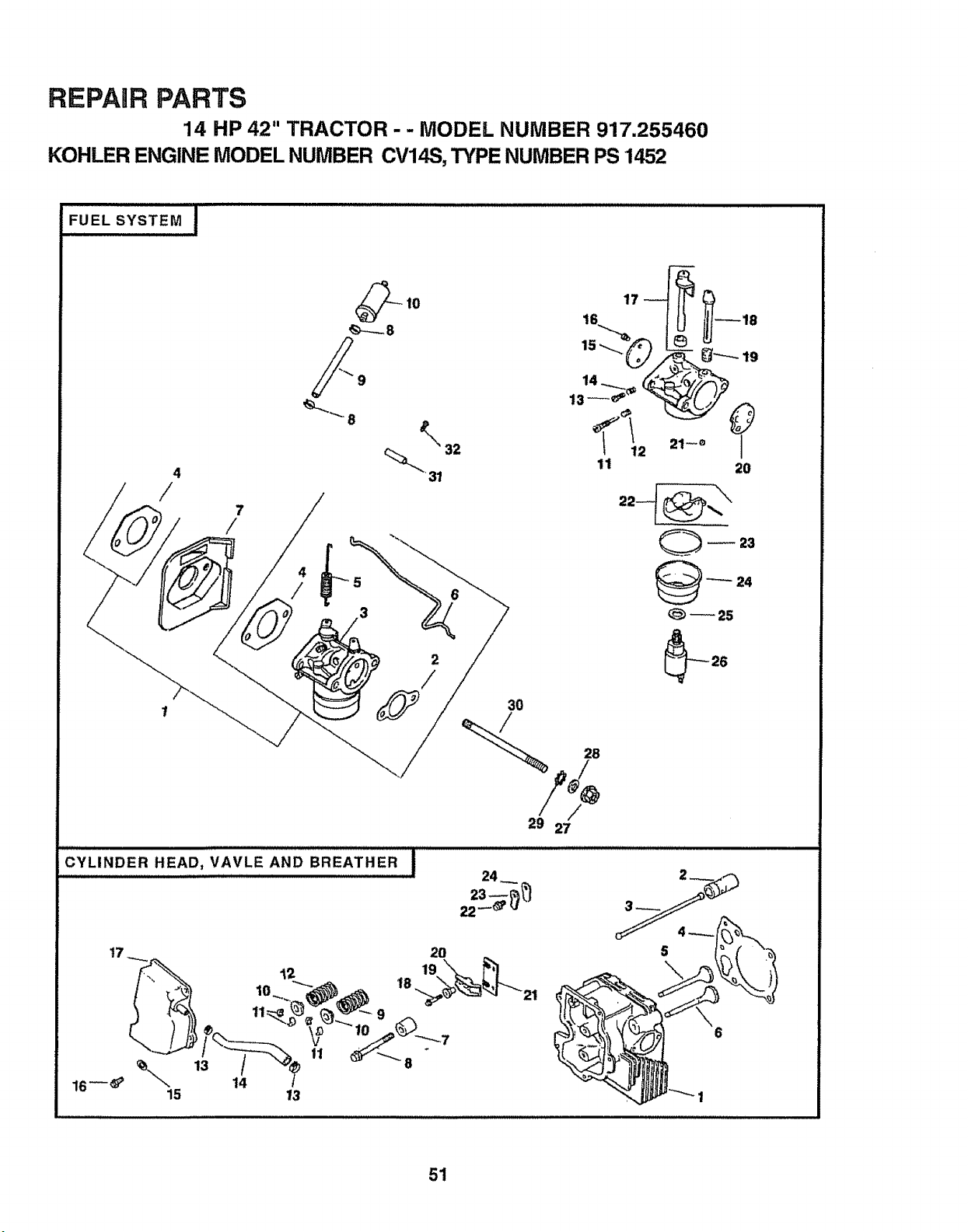
REPAIR PARTS
14 HP 42" TRACTOR - - MODEL NUMBER 917.255460
KOHLER ENGINE MODEL NUMBER CV14S, TYPE NUMBER PS 1452
FUEL SYSTEM I
4
/
7
/
15"-_,_:/_ _ __.
13_
'!'L ,,-°V
11 20
_ 23
_ 24
_25
3O
CYLINDERt'lEAO,VAV'EANDB.EAT.ER!
t7 .__ 20 _
16--_' k 14 /
15 13
51
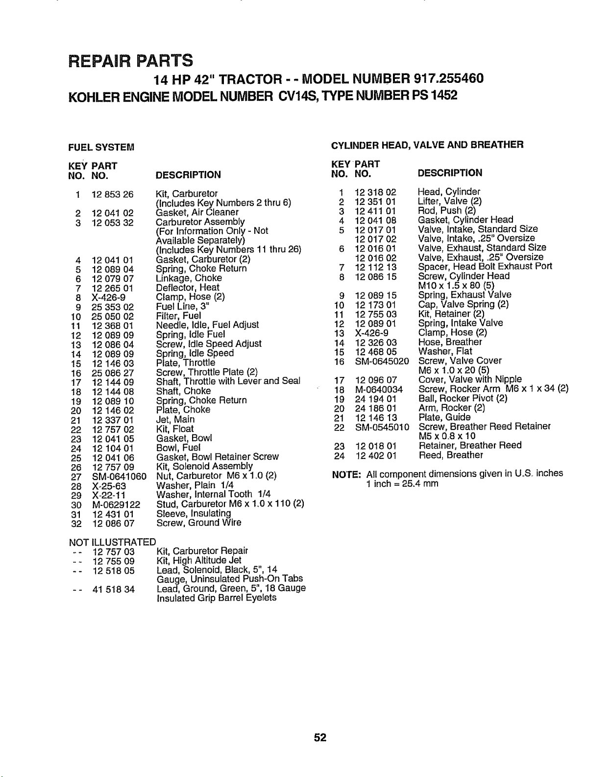
REPAIR PARTS
14 HP 42" TRACTOR - - MODEL NUMBER 917.255460
KOHLER ENGINE MODEL NUMBER CV14S, TYPE NUMBER PS 1452
FUEL SYSTEM
KEY PART KEYPART
NO. NO. DESCRIPTION NO, NO.
1 12 853 26
2 12 041 02
3 12 053 32
4 12 041 01
5 12 089 04
6 12 079 07
7 12 265 01
8 X-426-9
9 25 353 02
10 25 050 02
11 1236801
12 !2 089 09
13 12 O86 04
14 12 089 09
15 12 146 03
16 25 086 27
17 12 144 09
18 12 144 08
19 12 089 t0
20 12 146 02
21 12 337 01
22 12 757 02
23 12 041 05
24 12 t04 01
25 12 041 06
26 t2 757 09
27 SM-0641060
28 X-25-63
29 X-22-I1
30 M-0629122
31 12 431 01
32 12 086 07
Kit, Carburetor
(Includes Key Numbers 2 thru 6)
Gasket, Air Cleaner
Carburetor Assembly
(For Information Only - Not
Available Separately)
(includes Key Numbers 11 thru 26)
Gasket, Carburetor (2)
Spring, Choke Return
Linkage, Choke
Deflector, Heat
CIanTp,Hose (2)
Fuel Line, 3"
Filter; Fuel
Needle, Idle, Fuel Adjust
Spring, idle Fuel
Screw, Idle Speed Adjust
Spring, Idle Speed
Plate, Throttle
Screw, Throttle Plate (2)
Shaft, Throttle with Lever and Seal
Shaft, Choke
Spring, Choke Return
Plate, Choke
Jet, Main
Kit, Float
Gasket, Bowl
Bowl, Fuel
Gasket, Bowl Retainer Screw
Kit, Solenoid Assembly
Nut, Carburetor M6 x 1 o0(2)
Washer, Plain 1/4
Washer, internal Tooth 1/4
Stud, Carburetor M6 x 1.0 x 110 (2)
Sleeve, Insulating
Screw, Ground Wire
NOT ILLUSTRATED
12 757 03 Kit, Carburetor Repair
!2 755 09 Kit, High Altitude Jet
12 518 05 Lead, Solenoid, Black, 5", t4
Gauge, Uninsulated Pus,h-On Tabs
41 518 34 Lead, Ground, Green, 5,18 Gauge
insulated Grip Barrel Eyelets
CYLINDER HEAD, VALVE AND BREATHER
DESCRIPTION
1 12 318 02
2 12 351 01
3 12411 01
4 12 041 08
5 1201701
12 017 02
6 12 016 01
t2 016 02
7 12 112 13
8 12 086 15
9 12 089 15
10 12 173 01
11 12 755 03
12 12 089 01
13 X-426-9
14 12 326 03
15 !2 468 05
16 SM-0645020
17 12 096 07
18 M-0640034
19 24 194 01
20 24 186 01
21 12 146 13
22 SM-0545010
23 12 018 0t
24 12 402 0t
Head, Cylinder
Lifter, Valve (2)
Rod, Push (2)
Gasket, Cylinder' Head
Valve, Intake, Standard Size
Valve, Intake, .25" Oversize
Valve, Exhaust, Standard Size
Valve, Exhaust, .25" Oversize
Spacer, Head Boit Exhaust Port
Screw, Cylinder Head
M10 x 1.5 x 80 (5)
Spring, Exhaust Valve
Cap, Valve Spring (2)
Kit, Retainer'(2)
Spring, Intake Valve
Clamp, Hose (2)
Hose, Breather
Washer, Flat
Screw, Valve Cover
M6 x 1.0 x 20 (5)
Cover, Valve with Nipple
Screw, Rocker Arm M6 x t x 34 (2)
Ball, Rocker Pivot (2)
Arm, Rocker (2)
Plate, Guide
Screw, Breather Reed Retainer
M5x0_8xt0
Retainer', Breather Reed
Reed, Breather
NOTE: Atl component dimensions given in U,,S,.inches
1 inch = 25°4 mm
52
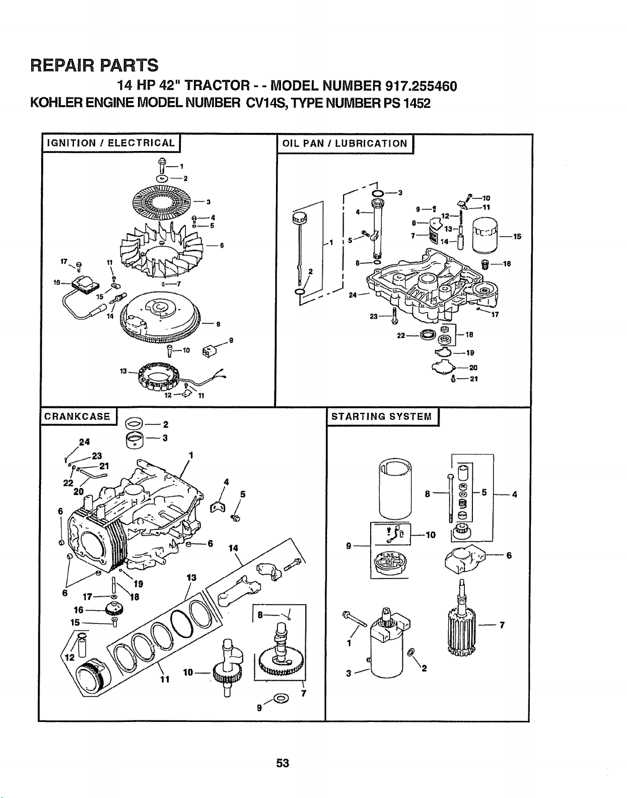
REPAIR PARTS
14 HP 42" TRACTOR - - MODEL NUMBER 917.255460
KOHLER ENGINE MODEL NUMBER CV14S, TYPE NUMBER PS 1452
IGNITIONIELECTRICALI
17_,._ 11
\
OIL PAN / LUBRICATION I
,.-+"1
,i- 0_3
I
J
OR,.KC,SEJ@__=
1
6 14
9
STARTING SYSTEM I
I"_ i
_7
53
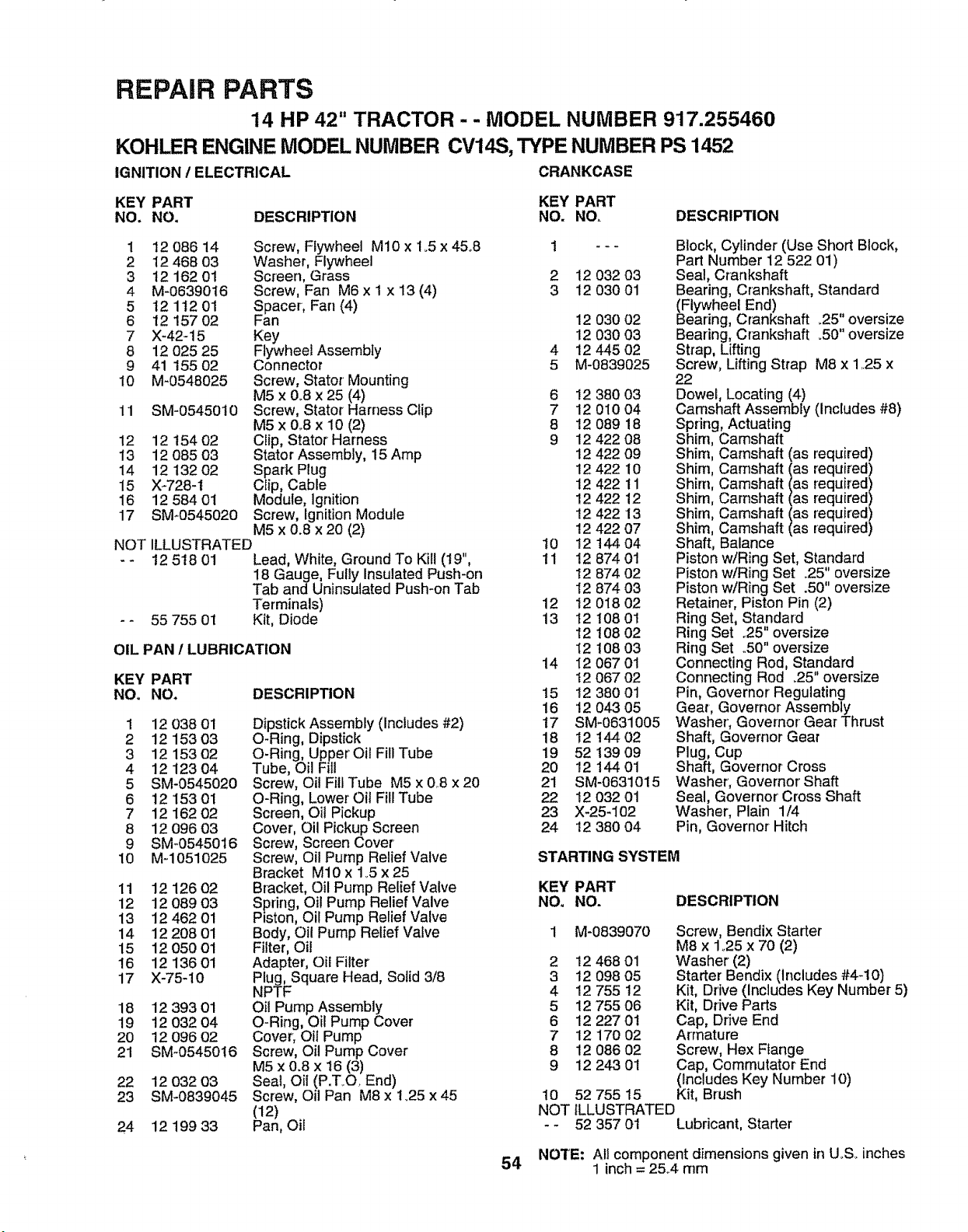
REPAIR PARTS
14 HP 42" TRACTOR - - MODEL NUMBER 917.255460
KOHLER ENGINE MODEL NUMBER CV14S, TYPE NUMBER PS 1452
IGNITION I ELECTRICAL CRANKCASE
KEY PART KEY PART
NO. NO, DESCRIPTION NO. NO. DESCRIPTION
1 12 086 14 Screw, Flywheel M10 x 1.5 x 45°8
2 12468 03 Washer, Flywheel
3 12 162 01 Screen, Grass
4 M-0639016 Screw, Fan M6 x 1 x 13 (4)
5 t2 112 01 Spacer, Far] (4)
6 12 157 02 Fan
7 X-42-15 Key
8 12 025 25 Flywheel Assembly
9 41 155 02 Connector
10 M_0548025 Screw, Stator Mounting
M5 x &8 x 25 (4)
11 SM-0545010 Screw, Stator Harness Clip
M5 x 0.8 x 10 (2)
12 12 !54 02 Clip, Stator Harness
13 12 085 03 Stator Assembly, 15 Amp
14 12 132 02 Spark Plug
15 X-728-I Clip, Cable
16 12 584 01 Module, Ignition
17 SM*0545020 Screw, Ignition Module
M5 x 0.8 x 20 (2)
NOT ILLUSTRATED
12 5t8 01 Lead, White, Ground To Kill (t9",
18 Gauge, Fully Insulated Push-on
Tab and Uninsulated Push-on Tab
Terminals)
55 755 01 Kit, Diode
OIL PAN I LUBRICATION
KEY PART
NOo NO.
DESCRIPTION
1
2
3
4
5
6
7
8
9
10
11
12
13
14
15
16
17
18
19
20
21
22
23
24
12 038 0i
12 153 03
12 153 02
12 123 04
SM-0545020
12 153 01
12 162 02
12 096 03
SM-0545016
M-1051025
12 126 02
12 089 03
12 462 01
12 208 01
12 050 01
12 136 01
X-75-10
12 393 01
12 032 04
12 096 02
SM-0545016
12 032 03
SM-0839045
12 199 33
Dipstick Assembly (Includes #2)
O-Ring, Dipstick
O-Ring, Upp..erOil Fill Tube
Tube, Oil Fill
Screw, Oil Fill Tube M5 x 0.8 x 20
O-Ring, Lower Oil Fill Tube
Screen, el! Pickup
Cover, Oil Pickup Screen
Screw, Screen Cover
Screw, Oil Pump Relief Valve
Bracket M10 x 1o5 x 25
Bracket, Oil Pump Relief Valve
Spring, Oil Pump Relief Valve
Piston, Oil Pump Relief Valve
Body, Oil Pump Relief Valve
Filter, Oil
Adapter', Oil Filter
Plug, Square Head, Solid 3/8
NPTF
el! Pump Assembly
O-Ring, Oil Pump Cover
Cover; Oil Pump
Screw, Oil Pump Cover
M5 x 0.8 x 16 (3)
Seal, Oil (P.ToO. End)
Screw, Oil Pan M8 x 1.25 x 45
(12)
Pan, Oil
t
2
3
4
5
6
7
8
9
10
11
12
13
14
15
16
17
18
19
2O
21
22
23
24
12 032 o3
12 030 01
12 030 02
12 030 03
12 445 02
M-0839025
12 380 03
12 010 04
12 089 18
12 422 08
12 422 09
12 422 10
12 422 11
12 422 12
12 422 13
12 422 07
12 144 04
12 874 01
12 874 02
12 874 03
t2 018 02
12 108 01
12 108 02
t2 108 03
12 067 01
I2 067 02
12 380 01
12 043 05
SM-0631005
t2 144 02
52 139 09
12 144 01
SM-0631015
12 O32 01
X-25-102
12 380 04
Block, Cylinder (Use Short Block,
Part Number 12 522 01)
Seal, Crankshaft
Bearing, Crankshaft, Standard
(Flywheel End)
Bearing, Crankshaft .25" oversize
Bearing, Crankshaft .50" oversize
Strap, Lifting
Screw, Lifting Strap M8 x 1.25 x
22
Dowel, Locating (4)
Camshaft Assembly (Includes #8)
Spring, Actuating
Shim, Camshaft
Shim, Camshaft (as required)
Shim, Camshaft (as required
Shim, Camshaft (as required
Shim, Camshaft (as required
Shim, Camshaft (as required
Shim, Camshaft (as required
Shaft, Balance
Piston w/Ring Set, Standard
Piston w/Ring Set .25" oversize
Piston w/Ring Set .50" oversize
Retainer, Piston Pin (2)
Ring Set, Standard
Ring Set °25" oversize
Ring Set ..50"oversize
Connecting Rod, Standard
Connecting Rod .25" oversize
Pin, Governor' Regulating
Gear, Governor Assembly
Washer', Governor Gear Thrust
Shaft, Governor Gear
Plug, Cup
Shaft, Governor Cross
Washer, Governor Shaft
Seal, Governor Cress Shaft
Washer, Plain 1/4
Pin, Governor Hitch
STARTING SYSTEM
KEY PART
NO, NO. DESCRIPTION
1 M-0839070 Screw, Bendix Starter
M8 x 1o25 x 70 (2)
2 12 468 01 Washer (2)
3 12 098 05 Starter Bendix (Includes #4-10)
4 12 755 12 Kit, Drive (Includes Key Number 5)
5 12 755 06 Kit, Drive Parts
6 12 227 0t Cap, Drive End
7 12 170 02 Armature
8 12 086 02 Screw, Hex Ffange
9 12 243 01 Cap, Commutator End
(Includes Key Number 10)
10 52 755 15 Kit, Brush
NOT ILLUSTRATED
- - 52 357 01 Lubricant, Starter
54 NOTE: All component dimensions given in U,,S. inches
1 inch = 25,.4 mm
GW ER'S
MANUAL
MODEL NO.
917.255460
HOW 3"0 ORDER
REPAIR PARTS
£RIIF fIMIIII +
14.0 HP
ELECTRIC START
3 in One Convertible
42" MOWER
AUTOMATIC (HYDROSTATIC)
DRIVE
LAWN TRACTOR
Each tractor has its own model number,, Each engine has
its own model number_
The model number for your tractor will be found on the
model plate located under the seat,,
The model number for your engine wilt be found on the
blower housing of the engine,
All parts listed herein may be ordered from any Sears,
Roebuck and Co+ Service Center/Department and most
Retail Stores,
WHEN ORDERING REPAIR PARTS, ALWAYS GIVE THE
FOLLOWING INFORMATION:
o PRODUCT- LAWN TRACTOR
= MODEL NUMBER - 917,255460
o ENGINE MODEL NO. - CV14S-PS1452
o PART NUMBER
° PART DESCRtPTION
Your Sears merchandise has added value when you
consider Sears has service units nationwide staffed with
Sears trained technicians ..... professional technicians
specifically trained to insure that we meet our pledge to
yotJ,we sewice what we sell,,
137807 Rev+3 06.03,93
................ +...................... ,, ,,,,,,,,,
Printed in tJoS.A_


