Loading ...
Loading ...
Loading ...
INSTALLING WHEEL KIT
The Sears Wheel Kit was designed to greatly improve
the portablility of your generator. You will need (2) 1/2"
wrenches and (2) 9/16" wrenches.
• Place two 4"x4" pieces of wood on the floor. With
another person helping, carefully lift the generator and
place on top of the wood supports. This will support
the weight of the gasoline engine and generator while
the wheels, brackets, and handle are installed. Also, it
will allow access to the underside of the generator for
hardware installation. Fuel tank should be drained
prior to installation. Make sure that the generator is
supported evenly, level and will not fall.
• Place a handle cap (7) onto each end of handle prior
to installation.
• The handle should be installed on the electrical outlet
end of the generator. Place one washer (12) on long
cap screws (11). Align the handle brackets with the
upper holes pre-drilled in the generator frame. Place
mentioned screws through frame and handle brackets.
Secure with lock nuts (8) and tighten.
Locate the engine support. Place one wheel bracket
(4) on top of support as shown in illustration below.
Align with the pre-ddlled holes insupport. Place 2
cap screws (9) through holes in bracket and support.
Secure with 2 lock nuts (8) and tighten.
Insert one shoulder bolt (2) into wheel (1). insert
threaded end of bolt through wheel bracket, secure
with lock nut (3) and tighten. Note: The wheel will
not rub frame if installed property.
• Repeat the above steps for the oppposite side.
• insert the threaded stud of rubber foot (10) through
the middle hole of the foot bracket (5). Secure with
lock nut (8) and tighten.
Locate the support under the electrical outlet end of
the generator. Position foot bracket (5), with rubber
foot installed, under the support and align the holes
in the foot bracket (5) with the slots in the support.
Place one cap screw (9) through each slot inthe
support and the holes in the foot bracket. Secure
with the lock nuts (8) and tighten.
Once completed, the wheel kit isready for use.
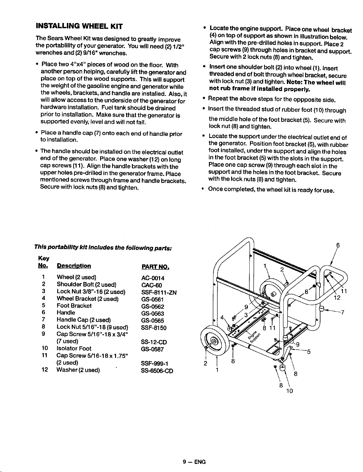
This portability kit includes the following parts:
Key
No. Descrh_tion ARTp_AR_T_r_.
1 Wheel (2 used) AC-0014
2 Shoulder Bolt (2 used) CAC-60
3 Lock Nut 3/8"-16 (2 used) SSF-8111-ZN
4 Wheel Bracket (2 used) GS-0551
5 Foot Bracket GS-0562
6 Handle GS-0563
7 Handle Cap (2 used) GS-0555
8 Lock Nut 5/16"-18 (9 used) SSF-6150
9 Cap Screw 5/16"-18 x 3/4"
(7 used) SS-12-CD
10 Isolator Foot GS-0587
11 Cap Screw 5/16-18 x 1.75"
(2 used) SSF-999-1
12 Washer (2 used) SS-6506-CD
2 8
10
11
12
9 -- ENG
Loading ...
Loading ...
Loading ...