Loading ...
Loading ...
Loading ...
5
12. Install the top cover of the rooftop
unit back and fasten the 10 screws
removed in step 1.
Wire Connection
DANGER
Electrical Shock Hazard
● Disconnect power before servicing.
● Failure to obey this warning could
result in death or serious injury.
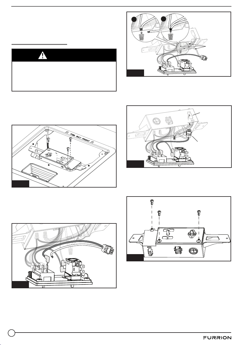
13. Unscrew the 3 screws on the
electrical control box, remove the
covers and controls attached to it
(Fig. 9).
Fig. 9
14. Plug the black wire of the connecting
harness, a 3-pin terminal interface
(provided), into the “H” pin of the
switch. (Fig. 10)
Fig. 10
15. Route neutral/white wire over to the
junction box, and connect with the
other neutral/white wires. (Fig 11)
Fig. 11
White Wires
ba
16. Install and lock the 3-pin terminal
interface onto the reserved opening
on the electrical control box.(Fig. 12)
3-pin terminal
interface
Reserved
opening
Fig. 12
17. Put all wires in the control box and
then install the box covers back and
tighten the 3 screws.(Fig. 13)
Fig. 13
18. Plug
the 3-pin connector of the heat
strip into the 3-pin terminal interface
on the control box.(Fig. 14)
Loading ...
Loading ...
Loading ...