Loading ...
Loading ...
Loading ...
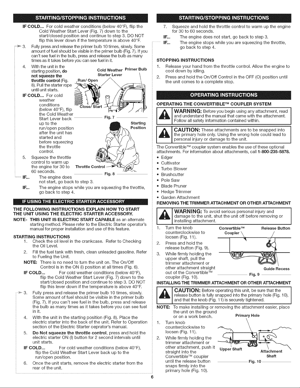
IFCOLD...Forcoldweatherconditions(below40°F),flipthe
ColdWeatherStartLever(Fig.7)downtothe
start/closedpositionandcontinuetostep3.DONOT
flipthisleverdownifthetemperatureisabove40°R
3. Fullypressandreleasetheprimerbulb10times,slowly.Some
amountoffuelshouldbevisibleintheprimerbulb(Fig.7).Ifyou
can'tseefuelinthebulb,pressandreleasethebulbasmany
timesasittakesbeforeyoucanseefuelinit.
4. Withtheunitinthe
startingposition,do
notsqueezethe
throttlecontrol(Fig.
8).Pullthestarterrope
untilunitstarts.
IFCOLD...Forcold
weather
conditions
(below40°F),flip
theColdWeather
StartLeverback
uptothe
run/openposition
aftertheunithas
startedand
beforesqueezing
thethrottle
control.
IF...
Cold Weather Primer Bulb
Starter Lever
Run/Open
Close/Start
Fig. 7
Starting
Position
5. Squeeze the throttle
control to warm up
the engine for 30 to
60 seconds.
Fig. 8
The engine does
not start, go back to step 3.
IF... The engine stops while you are squeezing the throttle,
go back to step 4.
THE FOLLOWING iNSTRUCTiONS EXPLAIN HOW TO START
THE UNiT USING THE ELECTRIC STARTER ACCESSORY.
NOTE= THIS UNiT IS ELECTRIC START CAPABLE as an alternate
starting method. Please refer to the Electric Starter operator's
manual for proper installation and use of this feature.
7.
IF...
i.............IF...
STARTING iNSTRUCTiONS
1. Check the oil level in the crankcase. Refer to Checking
the Oil Level.
2. Fill the fuel tank with fresh, clean unleaded gasoline. Refer
to Fueling the Unit.
NOTE: There is no need to turn the unit on. The On/Off
Control is in the ON (I) position at all times (Fig. 6).
IF COLD... For cold weather conditions (below 40°F),
flip the Cold Weather Start Lever (Fig. 7) down to the
start/closed position and continue to step 3. DO NOT
flip this lever down if the temperature is above 40°R
Fully press and release the primer bulb 10 times, slowly.
Some amount of fuel should be visible in the primer bulb
(Fig. 7). If you can't see fuel in the bulb, press and release
the bulb as many times as it takes before you can see fuel
in it.
4. With the unit in the starting position (Fig. 8). Place the
electric starter into the back of the unit. Refer to Operation
section of the Electric Starter oeprator's manual.
5. Do Not squeeze the throttle control, press and hold the
electric starter ON (I) button for 2 second intervals until
unit starts.
IF COLD... For cold weather conditions (below 40°F),
flip the Cold Weather Start Lever back up to the
run/open position.
6. Once the unit starts, remove the electric starter from the
rear of the unit.
Squeeze and hold the throttle control to warm up the engine
for 30 to 60 seconds.
The engine does not start, go back to step 3.
The engine stops while you are squeezing the throttle,
go back to step 4.
STOPPING iNSTRUCTiONS
1. Release your hand from the throttle control. Allow the engine to
cool down by idling.
2. Press and hold the On/Off Control in the OFF (O) position until
the unit comes to a complete stop.
OPERATING THE CONVERTIBLE TM COUPLER SYSTEM
WARNING: Before you begin using any attachment, read I
and understand the manual that came with the attachment.
!Follow all safety information contained within.
CAUTION: These attachments are to be snapped into i
the primary hole only. Using the wrong hole could lead to
I
personal injury or damage to the unit.
The Convertible TM coupler system enables the use of these optional
attachments. For information about attachments, call 1=800=235=5878.
• Edger
Cultivator
Turbo Blower
Brushcutter
Pole Saw
Blade Pruner
Hedge Trimmer
Garden Attachment
REMOVING THE TRIMMER ATTACHMENT OR OTHER ATTACHMENT
WARNING: To avoid serious personal injury and
damage to the unit, shut the unit off before removing or
installing attachment.
1. Turn the knob Convertible TM Release Button
counterclockwise to Co_, ___
loosen (Fig. 11).
1 "_ w/F
2. Press and hold the J " _-_
release button (Fig. 9).
3. While firmly holding the
upper shaft, pull the
trimmer attachment or
other attachment straight Guide Recess
out of the Convertible TM Fig. 9
coupler (Fig. 10).
iNSTALLING THE TRIMMER ATTACHMENT OR OTHER ATTACHMENT
6
_ AUTION: Before operating this unit, be sure that the
release button is fully snapped into the primary hole (Fig. 10),
and that the knob (Fig. 11) is securely tightened.
NOTE: To make installing or removing the attachment easier, place
1.
2.
the unit on the ground
or on a work bench. Primary Hole
Turn knob "f_"_-,-_ _.__,
counterclockwise to
loosen (Fig. 11).
While firmly holding the _ ,___
trimmer attachment or
other attachment, push it Upper Shaft
straight into the Attachment
Convertible TM coupler Shaft
until the release button Fig. 10
snaps firmly into the
primary hole (Fig. 10).
Loading ...
Loading ...
Loading ...