Loading ...
Loading ...
Loading ...
Disconnectthedd_lpress from the power source before
making any adiustments,
TO TiLTTHE TABLE (FIG, J)
NOTE: The tame is not shown in Fig. J for c_arity of
i_lustrationo
1, Loosen the bevel lock (!) with a wrench
2 Remove the horizontal _ocking pin (2) by turning the
nut (3) c_kvAse unti! the pin can be pui:Iedfrom the
hole_ far enough to ailow the table to move.
3. Tilt: the tame to the desired angle, using the bevem
scaJe (4) as a basic guide.
4. Tighten the beve_ lock.
5.
setting_
6, Turn the nu_{3) on the _cckJn£pin {2) counterd_se
to the end o_the threads°
7. Gentiy _ap the _ocklng pie unti_ it is seated _n_e
hole, Fingerotighten the _ut
8 Tighten the bevel lock wi_h a wrench.
Fig, J
TO SQUARE THE TABLE tO THE HEAD (F|G, K)
1 insert a 3" ddii bit (1) _ntothe chuck (2), and tighten
by turning the chuck barre_ counterclockwise
2, P_ace a combination square (4) on the table (3),as
sh_n, The dri]i bit should be paralle_ to the straight
edge of the squareo
3, If an adjustment is needed,/oosee _he b_el I_ock(5)
with a wrench,
4,, Square the table to the bi[ by ti_tingthe table.
5. Tighten the bore! iock when square
Fig. K
.......................................... 1
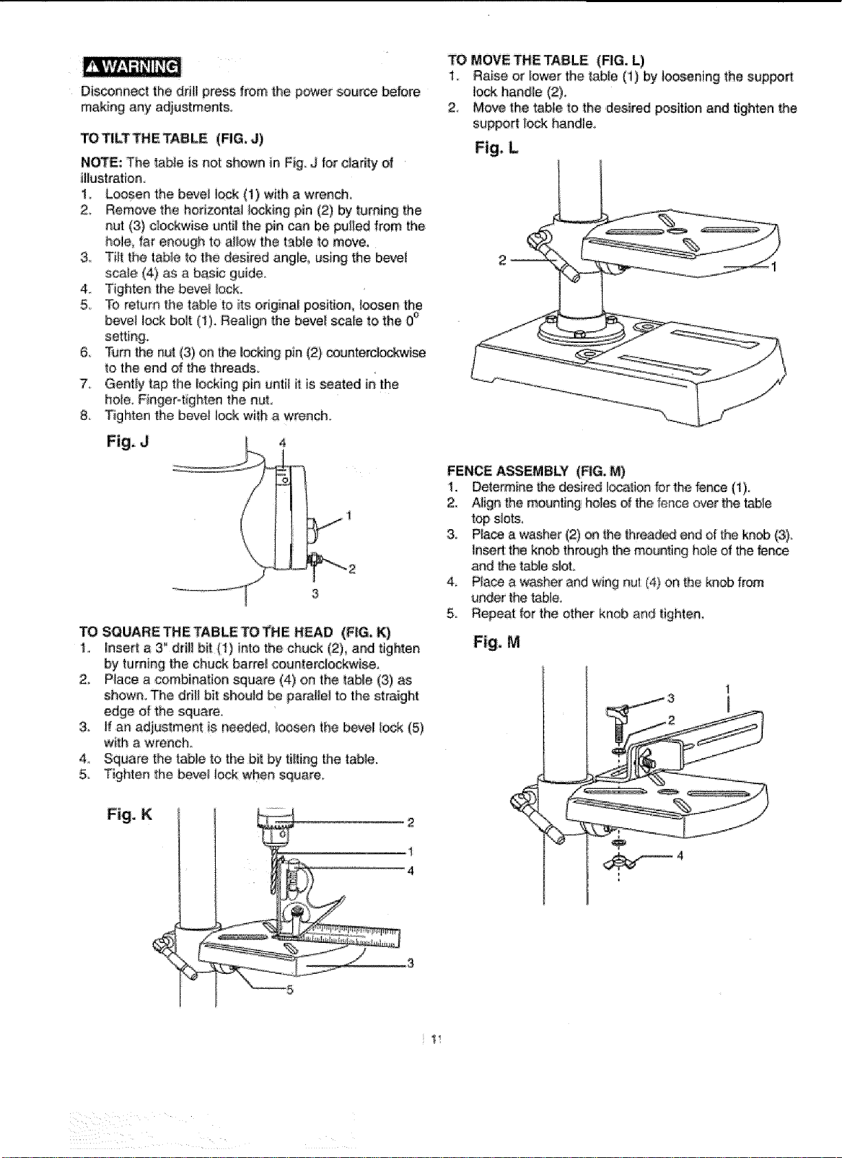
TO MOVE THE TABLE (_G. L)
1. Raise or lower the _ab_e(1) by _oosening the suppo_
lo_ handle (2)_
2 Move _he table to the desired _sitJon and tighten the
support lock handle
Fig, L
FENCE ASSEMBLY (FIG, M)
1. Determine _he desired I_a_ion for _hefence {t)o
2. Align the mounting holes d the fence ever the _ble
top sJetso
3, PAce a washer (2) on _he#_rea_ e_ of the knob (3).
_nseRthe knob through the mounting hole d the fete
arid the table slot
4, Place a washer and wing nut (4) on the knob from
un_r the table,
5, Repeat for the other knob and tighten,
Fig, M
Loading ...
Loading ...
Loading ...