Loading ...
Loading ...
Loading ...
Pg. #6
Pg. #7
2
2
.
.
MOUNTING
INSTALL MOUNTING BRACKET
- Install J-Hook through centre of outlet box and into the wooden joist.
- Secure mounting bracket and rubber gaskets to outlet box.
- Hang the safety cable onto the J-hook.
WARNING: To Reduce The Risk Of Fire, Electric Shock, Or Personal
Injury, Mount To UL/CSA Listed Outlet Box Marked Acceptable for
Fan Support And Use Mounting Screws Provided With The Outlet Box.
Canopy
Rubber Ring
Motor
Canopy
Yoke Screws
& Washers
Rubber Bushing
FLUSH MOUNT
- Remove rubber ring from canopy.
- Place canopy on fan housing by aligning 3 larger holes of canopy over
3 existing screws on the motor housing.
- Secure canopy to motor housing by placing 3 screws and washers
(supplied in hardware package) in the 3 smaller holes in the canopy.
B
B
Fig. 3f
Fig. 3g
3
3
.
.
- Hang fan on temporary hook or mounting bracket.
Make the following wire connections to the receiver unit (see fig. 6) using the
wire nuts supplied.
-
connect GREEN fan wire to BARE (ground) wire.
-
connect BLACK receiver unit wire to BLACK supply wire.
- connect WHITE receiver unit wire to WHITE supply wire.
- connect WHITE receiver unit wire (MOTOR N) to WHITE fan wire.
- connect BLACK receiver unit wire (MOTOR L) to BLACK fan wire.
- connect BLUE receiver unit wire (FOR LIGHT) to BLUE light wire.
B
-
After making the wire connections, ensure the wires should be spread
apart with the grounded conductor and the equipment-grounding
conductor on one side of the outlet box and the ungrounded conductor
on the other side of the outlet box.
-
Ensure the splices after being made should be turned upward and
pushed carefully up into the outlet box.
Ceiling
Outlet box Screws
(not provided)
Fig.4a
Tomporary
Hook
Canopy
Safety
Cable
Fig.4c
J-Hook
Safety
Cable
Canopy
Fig.4b
J-Hook
Wood Joist
Outlet Box
Rubber Gasket
Mounting Bracket
Diagram Fig.4b is for Downrod Mount.
Diagram Fig.4c is for Flush Mount.
ELECTRICAL HOOK-UP
4
4
.
.
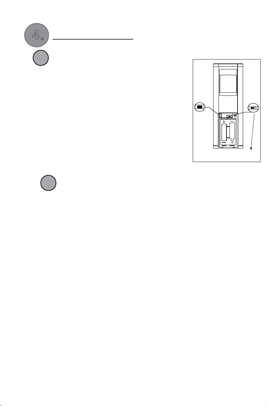
DC1.5V/ AAA*2pcs, not included), use a ball pen
please make sure not learn in other receiver.
bulb is used, then slide switch to the " DIM" position.
A
Fig.5
LEARNING PROCESS
-. After installing the unit and power on, open battery cover (with battery,
to press and hold the ”LEARN” key 1~3seconds.
FAN will be turn off and then FAN turn ON at
medium speed, which indicate that learning
process finished. Please note that must press
the “LEARNING KEY" within 30 seconds after
power on. If just replac batteries,no need to
re-learn.
-.Please note that the transmitter can learn in
multiple receiver, when doing learing process
LIGHT FUNCTION SELECT SWITCH
-.If you install an energy savongs bulbs such as a
fluorescent in your ceiling fan, slide the function
switch to " O" position and if a regular incandescent
LIGHT FUNCTION
SELECT SWITCH
LEARN
O/ DIM
AAA DC 1 . 5 V
AAA DC 1 . 5 V
Loading ...
Loading ...
Loading ...