operator's
manual
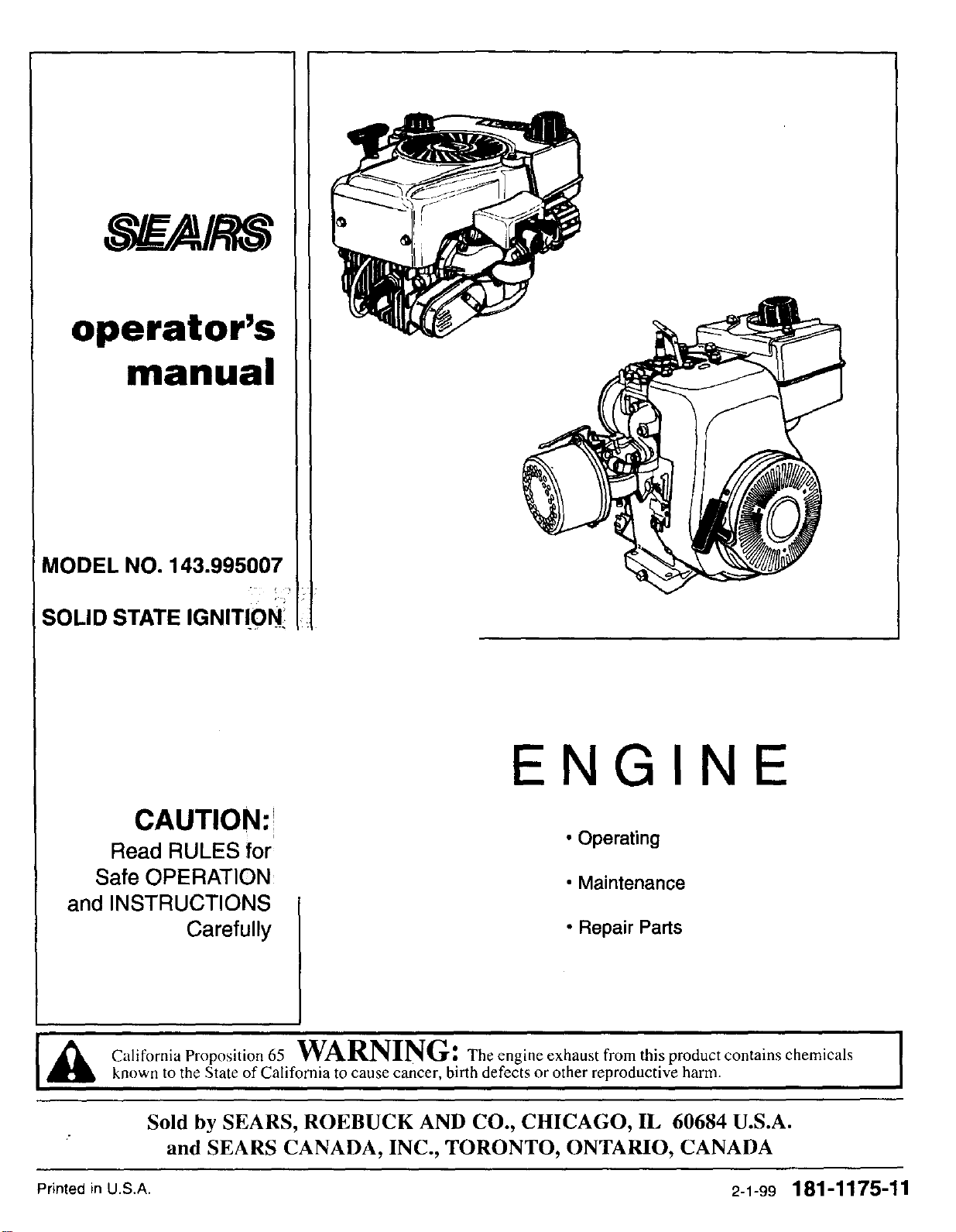
MODEL NO. 143.995007
SOLID STATE IGNITION_
CAUTION:!
Read RULES for
Safe OPERATION
and INSTRUCTIONS
Carefully
ENGIN
• Operating
• Maintenance
• Repair Parts
_ CaliforniaProposition65WARNING: The engine exhaust from this product contains chemicals [
known to the State of California to cause cancer, birth defects or other reproductive harm.
Sold by SEARS, ROEBUCK AND CO., CHICAGO, IL 60684 U.S.A.
and SEARS CANADA, INC., TORONTO, ONTARIO, CANADA
Printed in U.S.A. 2-1-99 181-1175-11
IIIIIllllll IIllllllllll
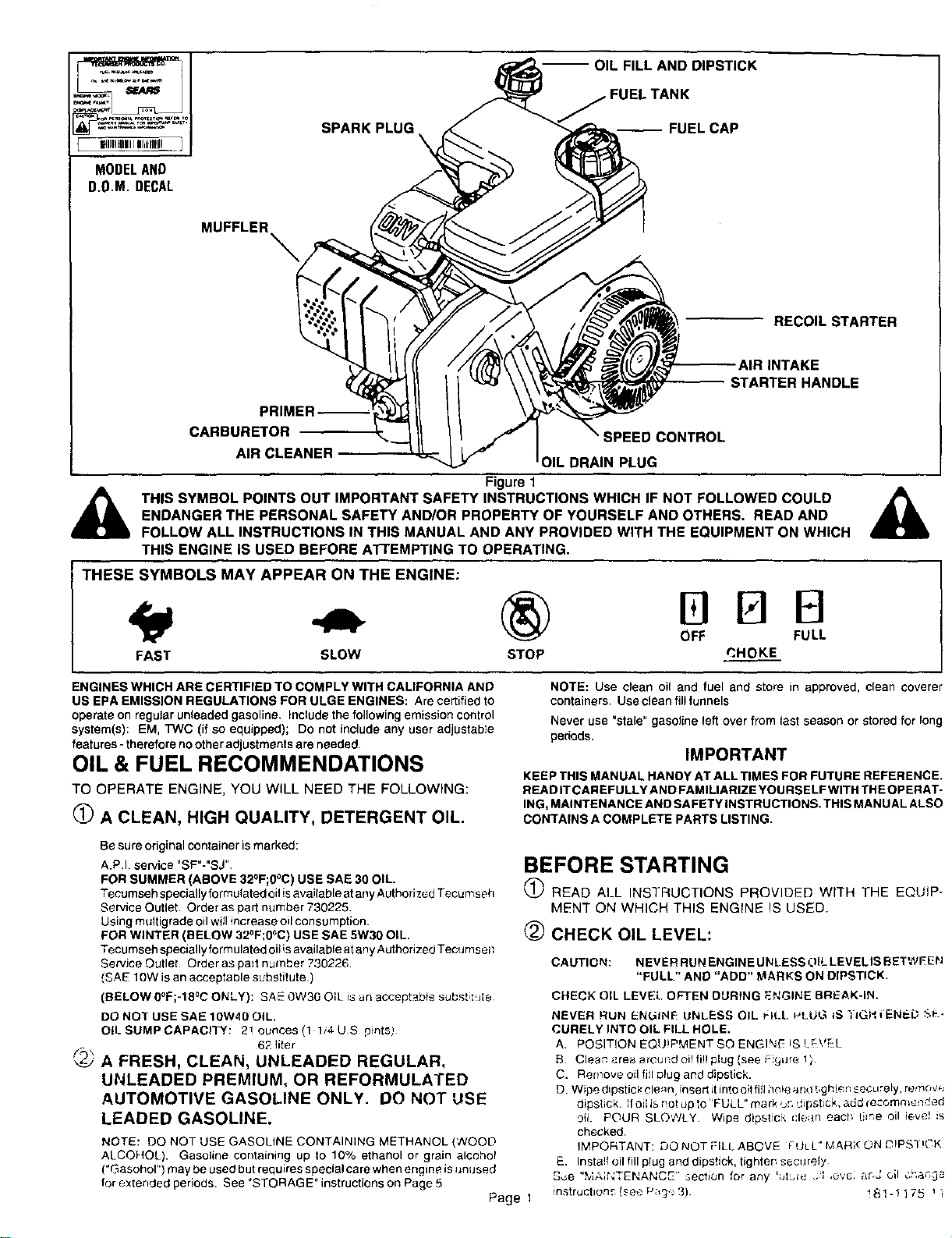
MODELAND
D.O.M. DECAL
SPARK PLUG
\
I OIL FILL AND DIPSTICK
FUEL TANK
_FUEL CAP
MUFFLER
\
RECOIL STARTER
--AIRINTAKE
STARTER HANDLE
PRIMER--'
CARBURETOR SPEED CONTROL
AIR CLEANER
OIL DRAIN PLUG
Figure 1
THIS SYMBOL POINTS OUT IMPORTANT SAFETY INSTRUCTIONS WHICH IF NOT FOLLOWED COULD
ENDANGER THE PERSONAL SAFETY AND/OR PROPERTY OF YOURSELF AND OTHERS, READ AND
FOLLOW ALL INSTRUCTIONS IN THIS MANUAL AND ANY PROVIDED WITH THE EQUIPMENT ON WHICH
THIS ENGINE IS USED BEFORE A'rrEMPTING TO OPERATING.
THESE SYMBOLS MAY APPEAR ON THE ENGINE:
OFF FULL
FAST SLOW STOP P,HOKE
ENGINES WHICH ARE CERTIFIED TO COMPLY WITH CALIFORNIA AND
US EPA EMISSION REGULATIONS FOR ULGE ENGINES: Are certified to
operate on regular unleaded gasoline. Include the following emission control
system(s): EM, TWC (if so equipped); Do not include any user adjustable
features - therefore no other adjustments are needed.
OIL & FUEL RECOMMENDATIONS
TO OPERATE ENGINE, YOU WILL NEED THE FOLLOWING:
(_ A CLEAN, HIGH QUALITY, DETERGENT OIL.
Be sure original container is marked:
A.P.I. service "SF"-"SJ"
FOR SUMMER (ABOVE 32°F;0°C) USE SAE 30 OIL.
Tecumseh speciallyformutated oil isavaitable atany Authorized Tecumseh
Service Outlet. Order as part number 730225.
Using muitigrade oil will increase oil consumption.
FOR WINTER (BELOW 32°F;0°C) USE SAE 5W30 OIL.
Tecumseh specially formulated oiiis available at any Authorized Tecumsen
Service Outlet Order as pa_t number 730226
!SAE 10W is an acceptable substitute.)
(BELOW O_F;-18aCONLY): SAE 0W30 OIL is an acceptab!e substitute
DO NOT USE SAE 10W40 OIL.
OIL SUMP CAPACITY: 2! ounces (1 1/4 US pints)
62 liter
(2) A FRESH, CLEAN, UNLEADED REGULAR,
UNLEADED PREMIUM, OR REFORMULATED
AUTOMOTIVE GASOLINE ONLY. DO NOT USE
LEADED GASOLINE.
NOTE: DO NOT USE GASOLINE CONTAINING METHANOL (WOOD
ALCOHOL). Gasoline containing up to 10% ethanol or grain alcohol
("Gasohor') may be used but requires special care when engine isunused
for extended periods. See "STORAGE" instructions on Page 5
Page 1
NOTE: Use clean oil and fuel and store in approved, clean coverer
containers. Use clean fill funnels
Never use "stale" gasoline left over from last season or stored for long
pedods.
IMPORTANT
KEEP THIS MANUAL HANDY AT ALL TIMES FOR FUTURE REFERENCE.
READ IT CAREFULLY AND FAMILIARIZE YOURSELF WITH THE OPERAT-
ING, MAINTENANCE AND SAFETYINSTRUCTIONS. THIS MANUAL ALSO
CONTAINS A COMPLETE PARTS LISTING.
BEFORE STARTING
(_) READ ALL INSTRUCTIONS PROVIDED WITH THE EQUiP-
MENT ON WHICH THIS ENGINE IS USED.
CHECK OIL LEVEL:
CAUTION: NEVER RUN ENGINE UNLESS OIL LEVELIS BETWEEN
"FULL" AND "ADD" MARKS ON DIPSTICK.
CHECK OIL LEVEL OFTEN DURING ENGINE BREAK-IN.
NEVER RUN ENL_iNE UNLESS OIL _lt_t. =-,LUG_S TIGHi'ENED S_.-
CURELY INTO OIL FILL HOLE,
A. POSITION EQU!PMENT SO ENGI'S_ !S ! _\'EL
B Clean area around oil fill plug (see eeure 1 )
C. Remove oil fill plug and dipstick.
D Wipe dipstick ele_n, insert it into oil fillho!e and t_gh!en securely, remove
dips{Jck. Ifoil is not up to IIFULL" mark un dipstick, add rec.omme=ided
oit. POUR SLOWLY Wipe dipstick clean eacl_ time oil ieve! is
checked
IMPORTANT: DO NOT FILL ABOVE FtJL{." MAR;< ON D!PSI !CK
E. Insta!l oil fill plug arid dipstick, tighter, sec_lrely
See "MAINTENANCE" _ection for any ';Jtb_c .] ,evG: ar,_ oil Ch,_¢_
instructions (see P;,g, 3) ! 81 - ! 175 _i
(_) FILL FUEL TANK
with gasoline as specified in the preceding "OIL & FUEL
RECOMMENDATIONS" item 2.
NEVER MIX OIL WITH GASOLINE
Never use "stale" gasoline left over from last season or stored for long
periods.
,_ NEVER FILL FUEL TANK INDOORS, NEVER FILL FUEL TANK WHEN
ENGINE IS RUNNING OR HOT, DO NOTSMOKE WHEN FILLING FUEL
TANK.
_ NEVER FILL FUEL TANK COMPLETELY. FILL TANK TO 1/2" BELOW
BOTrOM OF F LLER NECK TO PROV DE SPACE FOR FUEL EXPAN-
I SION. WIPE ANY FUEL SPILLAGE FROM ENGINE AND EQUIPMENT
l BEFORE STARTING ENGINE.
_ANY LIQUEFIED pETROLEUM (LPG) OR NATURAL GAS FUEL SYS-
TEM MUST BE LEAKPROOF AND MEET ALL APPLICABLE CODES
L AND REGULATIONS.
(_ CHECK THE FOLLOWING:
STOPPING
(_ Moveequipmentcontroloranyignitionstopswitehonengineto
STOP or OFF (see equipment manufacturer's instructions).
_) AFTER ENGINE IS STOPPED:
DISCONNECT SPARK PLUG WIRE FROM SPARK PLUG AND
KEEP IT AWAY FROM SPARK PLUG.
TURN IGNITION SWITCH KEY (IF SO EQUIPPED) TO "OFF" POSI-
TION AND REMOVE KEY FROM SWITCH. THIS WILL REDUCE THE
POSSIBILITY OF UNAUTHORIZED STARTING OF ENGINE WHILE
EQUIPMENT IS NOT IN USE.
NEVER STORE ENGINE WITH FUEL IN TANK INDOORS OR IN
ENCLOSED, POORLY VENTILATED AREAS, WHERE FU EL FUMES
MAY REACH AN OPEN FLAME, SPA RKOR PILOT LIGHT AS ON A
FURNACE, WATER HEATER, CLOTHES DRYER OR OTHER GAS
APPLIANCE
,_A. BE SURE EQUIPMENT IS IN NEUTRAL GEAR WITH CLUTCHES,
BELTS, CHAINS AND SAFETY SWITCHES DISENGAGED. (FUL-
l LOW EQUIPMENT MANUFACTURER'S INSTRUCTIONS.) THIS
SHOULD PLACE ANY SAFETY SWITCHES IN SAFE STARTING
POSITION.
S. Be sure spark plug wire isattached to spark plug (see Figure 1).
C. SesureanyignitionswitchonengineorequipmentisinON, RUNor-
START position.
STARTING
,_ NEVER RUN ENGINE INDOORS OR IN ENCLOSED, POORLY VENTI-
LATED AREAS ENG NE EXHAUST CONTA NS CARBON MONOX-
IDE, AN ODORLESS AND DEADLY GAS (CARBON MONOXIDE IS
ALSO PRESENT IN ENGINE EXHAUST FROM LIQUID PETROLEUM
(LPG'JAND NATURAL GAS FUEL SYSTEMS).
_k KEEP HANDS, FEET, HAIR AND LOOSE CLOTHING AWAY FROM
ANY MOVING PARTS ON ENGINE AND EQUIPMENT.
,_WARNING: TEMPERATURE OF MUFFLER AND NEARBY AREAS
MAY EXCEED 150°F (65aC). AVOID THESE AREAS.
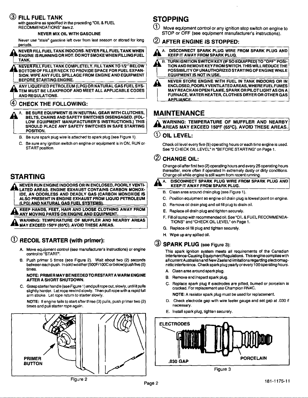
(_ RECOIL STARTER (with primer):
A.
B.
C.
Move equipment control (see manufacturer's instructions) or engine
controlto "START'.
Push primer 5 times (see Figure 2). Wait about two (2) seconds
between each push. Incold weather (500F/100C orbelow) pushfive (5)
times.
NOTE: PRIMER MAY BE NEEDEDTO RESTARTA WARM ENGINE
AFTER A SHORT SHUTDOWN.
Grasp starter handre(see Figure 1)and pullrope out,slowly, untilitpulls
slightly harder. Let rope rewind slowly. Then pull rope with a rapid full
arm stroke. Let rope return to starter slowry.
NOTE: If engine fails to start after three (3) pulis, push primer two (2)
times and pull starter rope again.
PRIMER
BUTTON
MAINTENANCE
,_WARNING: TEMPERATURE OF MUFFLER AND NEARBY_
AREAS MAY EXCEED 150°F (65°C). AVOID THESE AREAS._
OIL LEVEL:
Check oiJlevel every five (5) operating hours or each time engine isused.
See "2 CHECK OIL LEVEL" in "BEFORE STARTING" on Page 1.
_) CHANGE OIL:
Change oil after firsttwo (2) operating hours and every 25 operating hours
thereafter, more often if operated in extremely dusty or dirty conditions.
Change oilwhile engine isstill warm from recent running,
,_A. DISCONNECT SPARK PLUG WIRE FROM SPARK PLUG AND[
KEEP iT AWAY FROM SPARK PLUG.
_J
B. Ctean area around drain ptug (see Figure 1).
C. Position equipment so engine oildrain plug is lowest point on engine.
D. Remove oil drain plug and oilfill plug to drain oil.
E. Replace oil drain plugand tighten securely.
F. Filloilsump with recommended oil. See "OIL & FUEL RECOMMENDA-
TIONS" and "CHECK OIL LEVEL" on Page 1.
G. Replace oil fill plug and tighten securely.
H. Wipe up any spilled oil.
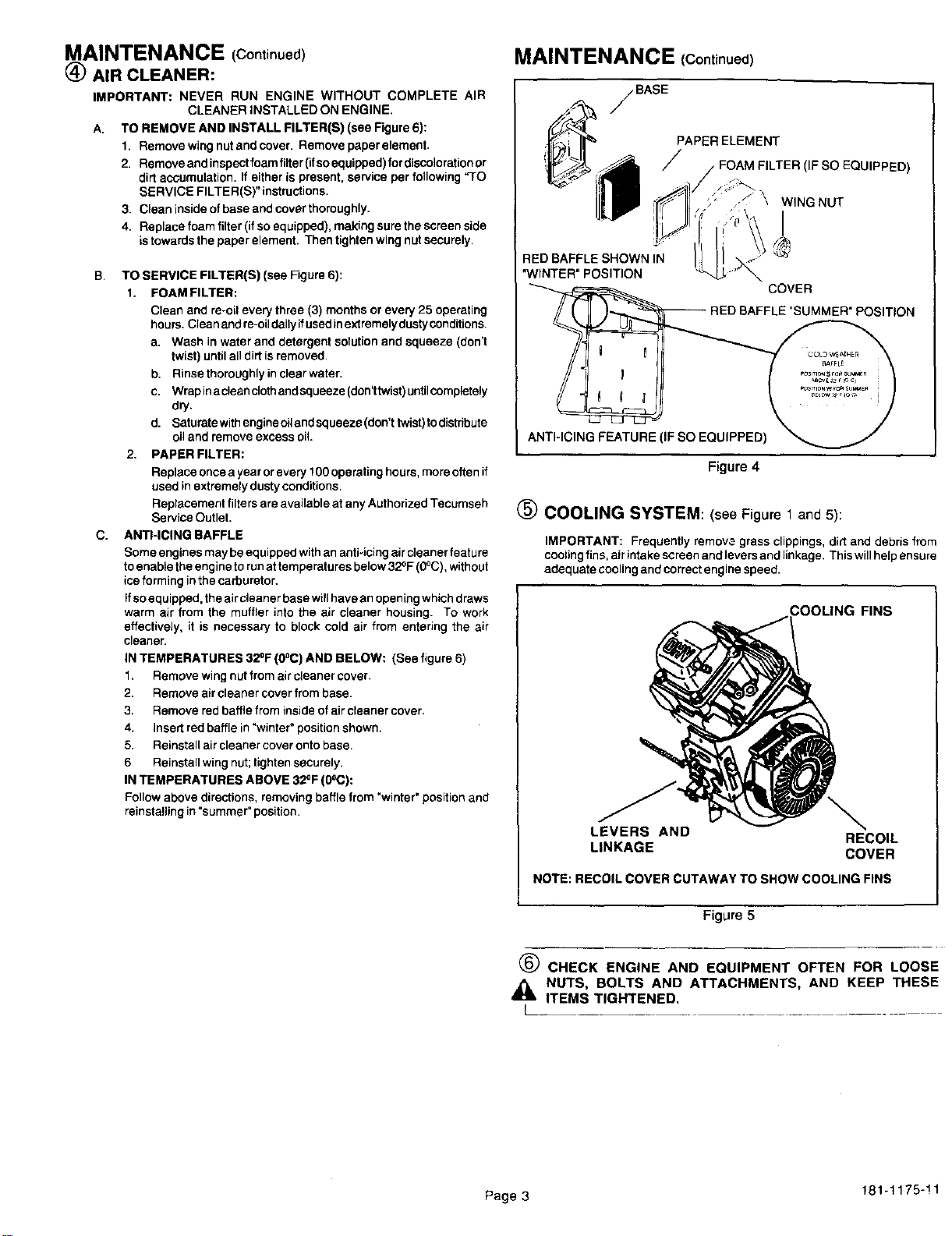
(_) SPARK PLUG (see Figure 3):
This spark ignition system meets all requirements of the Canadian
Interference-Causing Equipment Regulations. This engine complies with
allcurrantAustralian and New Zealand limitations regarding electromag-
netic interference. Check spark plug yearly or every 100 operating hours.
A. Clean area around spark plug.
B. Remove and inspect spark plug.
C. Replace spark plug if electrodes are pitted, burned or pomelain is
cracked. For replacement use Champion RN4C.
NOTE: A resistor spark plug must be used for replacement.
D. Check electrode gap with wire feeler gauge and set gap at .030 if
necessary.
E, Install spark plug, tighten securely,
Figure 3
Figure 2 181-1175-11
Page 2
MAINTENANCE (Continued)
@ AIR CLEANER:
IMPORTANT: NEVER RUN ENGINE WITHOUT COMPLETE AIR
CLEANER INSTALLED ON ENGINE.
A. TO REMOVE AND INSTALL FILTER(S) (see Figure 6):
1. Remove wing nut and cover. Remove paper element.
2. Remove and inspect foam filter(if soequipped) for discolorationor
dirt accumulation. If either is present, service per following "TO
SERVICE FILTER(S)" instructions.
3. Clean inside of base and cover thoroughly.
4. Replacefoamfilter(ifsoequipped),makingsurethescreenside
istowards the paper element. Then tighten wing nut securely,
B.
C.
TO SERVICE FILTER(S) (see Figure 6):
1. FOAM FILTER:
Clean and re-oil every three (3) months or every 25 operating
hours. Clean and re-oildailyifused inextremelydustyconditions.
a. Wash in water and detergent solution and squeeze (don't
twist) untilalldirt is removed.
b. Rinse thoroughly in clear water.
c. Wrap ina cleanclothand squeeze (don'ttwist)untilccmpletely
dry.
d. Saturatewithengineoilandsqueeze(don'ttwist)todistribute
oil and remove excess oil
2, PAPER FILTER:
Replace once a year or every 1O0ope rating hours, more offen if
used in extremely dusty conditions.
Replacement filters are available at any Authorized Tecumseh
Service Outlet.
ANTHCING RAFFLE
Some engines may be equipped with an anti-icing air cleaner feature
to enable the engine torunat temperatures below 32OF(0°C), without
ice forming in the carburetor.
Ifso equipped, the air cleaner base will have an opening which draws
warm air from the muffler into the air cleaner housing. To work
effectively, it is necessary to block cold air from entering the air
cleaner.
IN TEMPERATURES 32°F (0°C) AND BELOW: (See figure 6)
1. Remove wing nut from air cleaner cover.
2. Remove air cleaner cover from base.
3. Remove red baffle from inside of aircleaner cover,
4. insert red baffle in "winter" position shown.
5. Reinstall air cleaner cover onto base.
6 Reinstall wing nut;tighten securely.
IN TEMPERATURES ABOVE 32OF(0oC):
Fellow above directions, removing baffle from "winter" position and
reinstalling in "summer" position.
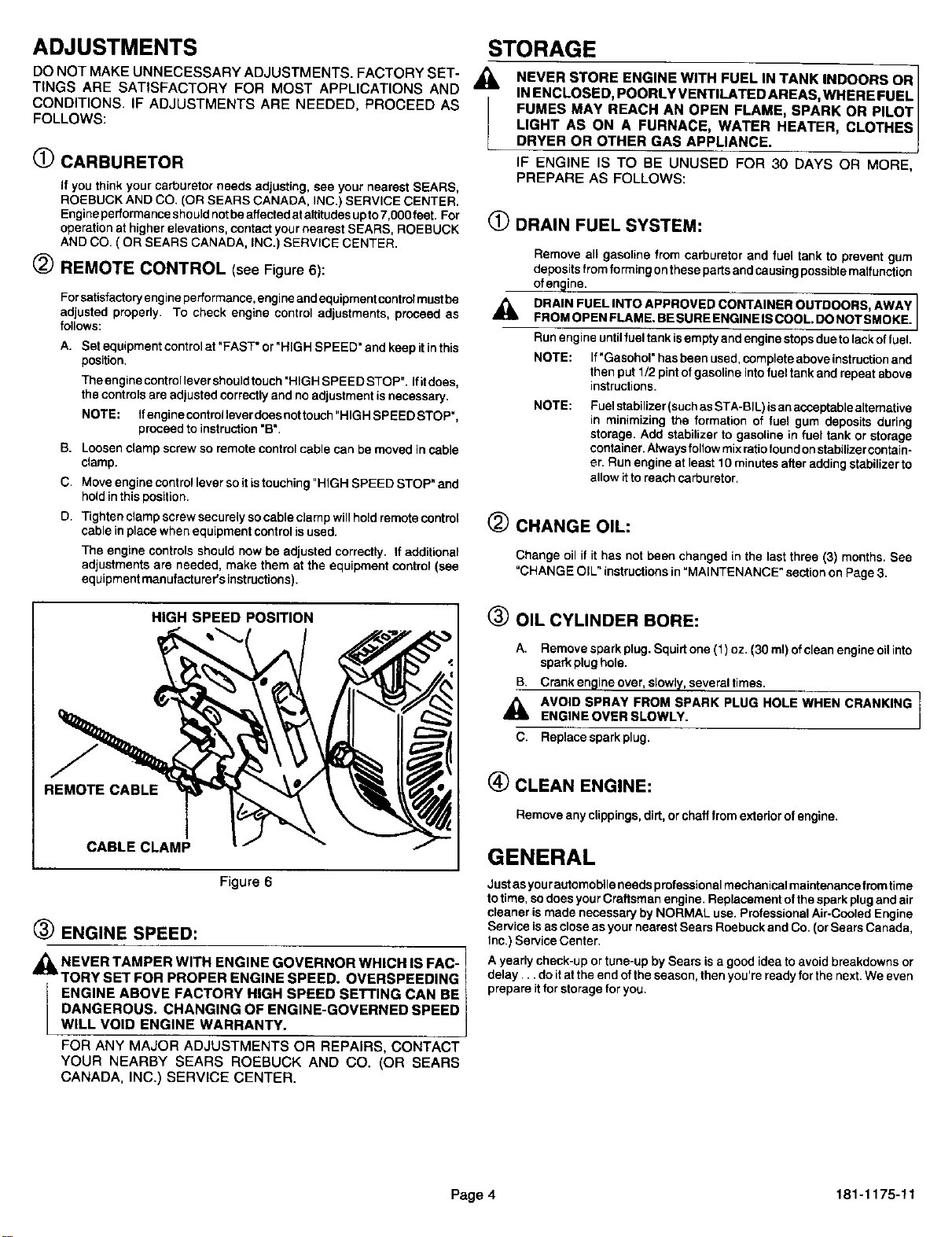
MAINTENANCE (Continued)
BASE
RED BAFFLE SHOWN IN
"WINTER" POSITION
" " 0 I
ANTI-ICING FEATURE
PAPER ELEMENT
/ FOAM FILTER (IF SO EQUIPPED)
•_'<'i>\ W,NGNUT
I
COVER
-- RED BAFFLE "SUMMER" POSITION
Figure 4
(_ COOLING SYSTEM: (see Figure 1 and5):
IMPORTANT: Frequently remove grass clippings, dirt and debris from
coolingfins, air intake screen and levers and linkage. This willhelp ensure
adequate cooling and correct engine speed.
COOLING FINS
LEVERS AND
RECOIL
LINKAGE COVER
NOTE: RECOIL COVER CUTAWAYTO SHOWCOOLING FINS
Figure 5
OLd) CHECK ENGINE AND EQUIPMENT OFTEN FOR LOOSE
_IL NUTS, BOLTS AND ATTACHMENTS, AND KEEP THESE
ITEMS TIGHTENED.
L
Page 3 181-1175-11
ADJUSTMENTS STORAGE
DO NOT MAKE UNNECESSARY ADJUSTMENTS. FACTORY SET- _k,
TINGS ARE SATISFACTORY FOR MOST APPLICATIONS AND
CONDITIONS. IF ADJUSTMENTS ARE NEEDED, PROCEED AS
FOLLOWS:
(_) CARBURETOR
If you think your carburetor needs adjusting, see your nearest SEARS,
ROEBUCK AND CO. (OR SEARS CANADA, INC.) SERVICE CENTER.
Engine performance should not be affected at altitudes up to7,000 feet. For
operation at higher elevations, contact your nearest SEARS, ROEBUCK
AND CO, ( OR SEARS CANADA, INC.) SERVICE CENTER.
(_) REMOTE CONTROL (see Figure 6):
For satisfactoryengine performance, engine and equipment controlmust be
adjusted properly. To check engine control adjustments, proceed as
follows:
A. Set equipment control at "FAST" or"HIGH SPEED" and keep itin this
position.
The engine controllever should touch"HIGH SPEED STOP". Ifit does,
the controls are adjusted correctly and no adjustment is necessary.
NOTE: Ifengine controllever does not touch "HIGH SPEED STOP",
proceed to instruction "B'.
B. Loosen clamp screw so remote control cable can be moved in cable
clamp.
C, Move engine control lever so it is touching "HIGH SPEED STOP" and
hold in this position.
D. Tighten clamp screw securely so cable cJamp will hold remote control
cable in place when equipment control is used.
The engine controls should now be adjusted correctly. If additional
adjustments are needed, make them at the equipment control (see
equipment manufacturer's instructions).
NEVER STORE ENGINE WITH FUEL IN TANK INDOORS OR
IN ENCLOSED, POORLY VENTILATED AREAS, WHERE FUEL I
FUMES MAY REACH AN OPEN FLAME, SPARK OR PILOT I
LIGHT AS ON A FURNACE, WATER HEATER, CLOTHES
DRYER OR OTHER GAS APPL ANCE. j
IF ENGINE IS TO BE UNUSED FOR 30 DAYS OR MORE,
PREPARE AS FOLLOWS:
(_) DRAIN FUEL SYSTEM:
Remove all gasoline from carburetor and fuel tank to prevent gum
deposits from forming on these parts and causing possible malfunction
ofen@ine.
,_ DRAIN FUELINTOAPPROVED CONTAINER OUTDOORS AWAY I
FROM OPEN FLAME. BE SURE ENGIN EIS COOL. DO NOT SMOKE.
Run engine until fuel tank isempty and engine stops due to lack of fuel.
NOTE: If"Gasohol" has been used, complete above instructionand
then put 1/2 pint of gasoline intofuel tank and repeat above
instructions.
NOTE:
Fuel stabilizer (suchas STA-BIL) is an acceptable alternative
in minimizing the formation of fuel gum deposits during
storage. Add stabilizer to gasoline in fuel tank or storage
container. Always follow mix ratio found on stabilizer contain-
er. Run engine at least 10 minutes after adding stabilizer to
allow itto reach carburetor.
CHANGE OIL:
Change oil if it has not been changed in the last three (3) months. See
"CHANGE OIL" instructions in "MAINTENANCE" section on Page 3.
HIGH SPEED POSITION
(_) OIL CYLINDER BORE:
A. Remove spark plug. Squirt one (1) oz. (30 ml) of clean engine oil into
spark plug hole.
B. Crank engine over, slowly, several times.
_k AVOID SPRAY FROM SPARK PLUG HOLE WHEN CRANKING
ENGINE OVER SLOWLY.
C. Replacesparkplug.
REMOTE CABLE
CABLE CLAMP
Figure 6
(_ ENGINE SPEED:
_ NEVER TAMPER WITH ENGINE GOVERNOR WHICH IS FAC- /
TORY SET FOR PROPER ENGINE SPEED. OVERSPEEDING |
ENGINE ABOVE FACTORY HIGH SPEED SETTING CAN BE
DANGEROUS. CHANGING OF ENGINE-GOVERNED SPEED |
WILL VOID ENGINE WARRANTY. ]
FOR ANY MAJOR ADJUSTMENTS OR REPAIRS, CONTACT
YOUR NEARBY SEARS ROEBUCK AND CO. (OR SEARS
CANADA, INC.) SERVICE CENTER.
(_ CLEAN ENGINE:
Remove any clippings, dirt, or chaff from exterior of engine.
GENERAL
Just as your automobile needs professional mechanical maintenance from time
to time, so does your Craftsman engine. Replacement of the spark plugand air
cleaner is made necessary by NORMAL use. Professional Air-Cooled Engine
Service isas close as your nearest Sears Roebuck and Co. (or Sears Canada,
Inc.) Service Center.
A yearly check-up or tune-up by Sears is a good idea to avoid breakdowns or
delay.., do itat the end ofthe season, then you're ready for the next. We even
prepare it for storage for you.
Page 4 181-1175-11
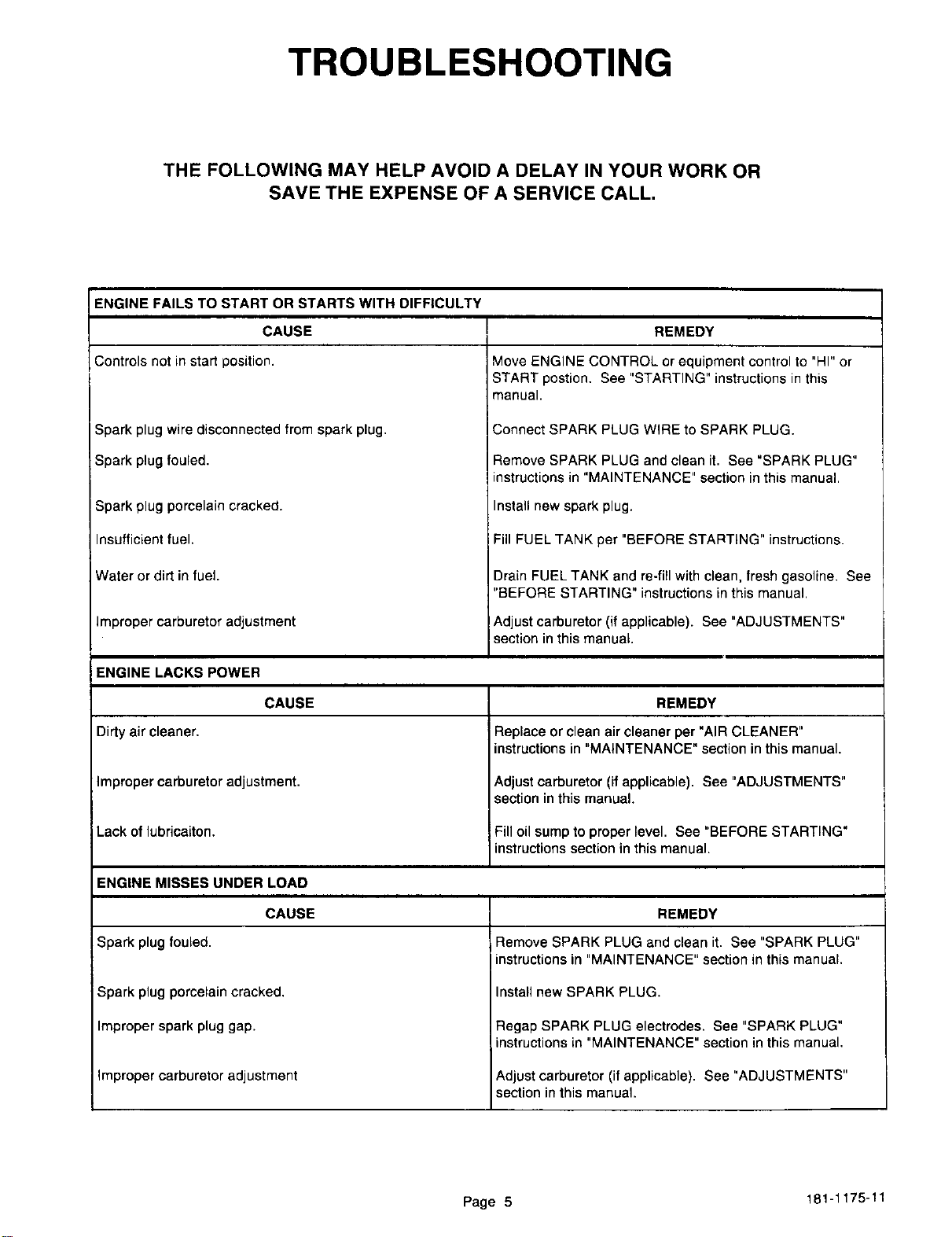
TROUBLESHOOTING
THE FOLLOWING MAY HELP AVOID A DELAY IN YOUR WORK OR
SAVE THE EXPENSE OF A SERVICE CALL.
ENGINE FAILS TO START OR STARTS WITH DIFFICULTY
CAUSE
Controls not in start position.
Spark plug wire disconnected from spark plug.
Spark plug fouled.
Spark plug porcelain cracked.
Insufficient fuel.
Water or dirt in fuel.
Improper carburetor adjustment
REMEDY
Move ENGINE CONTROL or equipment control to "HI" or
START postion, See "STARTING" instructions in this
manual.
Connect SPARK PLUG WIRE to SPARK PLUG.
Remove SPARK PLUG and clean it. See "SPARK PLUG"
instructions in "MAINTENANCE" section in this manual.
Install new spark plug.
Fill FUEL TANK per "BEFORE STARTING" instructions.
Drain FUEL TANK and re-fill with clean, fresh gasoline. See
"BEFORE STARTING" instructions in this manual.
Adjust carburetor (if applicable). See "ADJUSTMENTS"
section in this manual.
ENGINE LACKS POWER
CAUSE
Dirty air cleaner,
Improper carburetor adjustment.
Lack of lubricaiton.
REMEDY
IReplace or clean air cleaner per "AIR CLEANER"
instructions in "MAINTENANCE" section in this manual.
Adjust carburetor (if applicable). See "ADJUSTMENTS"
section in this manual.
Fill oil sump to proper level. See "BEFORE STARTING"
instructions section in this manual.
ENGINE MISSES UNDER LOAD
CAUSE
Spark plug fouled.
Spark plug porcelain cracked,
Improper spark plug gap.
Improper carburetor adjustment
REMEDY
Remove SPARK PLUG and clean it. See "SPARK PLUG"
instructions in "MAINTENANCE" section in this manual,
Install new SPARK PLUG.
Regap SPARK PLUG electrodes. See "SPARK PLUG"
instructions in "MAINTENANCE" section in this manual,
Adjust carburetor (if applicable). See "ADJUSTMENTS"
section in this manual.
Page 5 181-1175-11
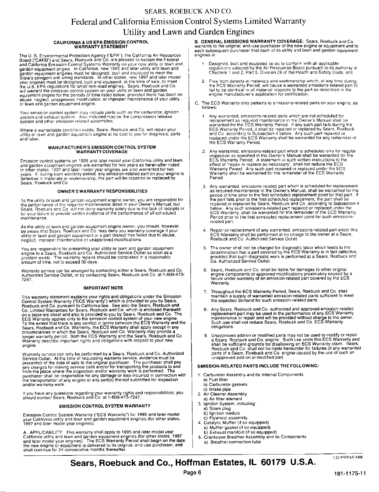
SEARS, ROEBUCK AND CO.
Federal and California Emission Control Systems Limited Warranty
Utility and Lawn and Garden Engines
CALIFORNIA & US EPA EMISSION CONTROL
WABRANTYSTATEMENT
The U S. Environmental Protection Agency ("EPA"), the California Air Resources
Board ("CARS") and Sears, Roebuck and Co. are pleased to explain the Federal
and California Emission Control Systems Warranty on your new utilily or lawn and
garden equipment engine In California, new 1995 and later utility and lawn and
garden equipment engines musl be designed, built and equipped to meet the
State's stringent anti-smog standards In other states, new 1997 and later model
year engines must be designed, built and equipped, at the time of sale, to meet
the U.S. EPA regulations for small non-road engines. Sears Roebuck and CO
will warrant the emission control system on your utildy or lawn and garden
equipment engine for the periods of time listed below, provided there has been no
abuse neglech unapproved modification, or improper maintenance of your utility
or lawn and garden equipment engine
Your emission control system nlay ;nclude parts such as the carburetor, ignition
System and exhaust system Also included may be the compression release
system and ether emission-related assemblies
Where a warrantable condition exists, Sears, Roebuck and Co will repair your
ublity or lawn and garden equipmellt engine at no cost to you for diagnosis, parts
and labor
MANUFACTURER'S EMISSION CONTROL SYSTEM
WARRANTY COVERAGE
Emission control systems on t995 and later model year Caldornia utilit_ and lawn
and garden equipment engines are warranted for two years as hereinafter holed
In other states, 1£97 and later model year engines are also warranted for two
years It during such warranIy period, any emission-related part on your engine is
defective in malerials or workmanship, the part will be repaired or replaced by
Sears, Roebuck and CO
OWNER'S WARRANTY RESPONSIBILITIES
AS the utility or iawn and garden equipment engine owner, you are responsible for
the performance of tile requ[re_ maintenance listed in your Owner's Manual, but
Sears, Roebuck andCo will not deny warranty solely due to thelackof receiptsor
for your failure to prov!de wPtten evidence of the performance of all scheduled
maintenance¸
As the utility or lawn and garden equipment engine owner, you should, however,
be aware that Sears, Roebuck and Co may deny you warranty coverage if your
utility or lawn and garden equipment or a part thereof has failed due to abuse,
neglect, improper maintenance or unapproved modifications
You are responsible for presenting your utility or lawn and garden equipment
engine to a Sears, Roebuck and Co, Authorized Service Outlet as soon as a
problem exists The warranty repairs should be completed in a reasonable
amount of time, not to exceed 30 days.
Warranty service can be arranged by contacting either a Sears, Roebuck and Co
Authorized Service Outlet, or by contacting Sears, Roebuck and Co. at 1-800-473-
7247.
IMPORTANTNOTE
This warranty statement explains your rights and obtigations under the Emission
Control System Warranty =ECS Warranty") which is provided to you by Sears,
Roebuck and Co. pursuant to California law. See a so the Sears, Roebuck and
Co. Limited Warranties for Sears, Roebuck and Co. which is enclosed therewith
on a separate sheet and also is provided to you by Sears, Roebuck and Co. The
ECS Warranty applies only to the emission controt system of your new engine,
TO the extent that there is any conflict in terms between the ECS Warranty and the
Sears, Roebuck and Co. Warranty, the ECS Warranty shall apply except in any
circumstances in which the Sears, Roebuck and Co Warranty may provide a
longer warranty period. Both the ECS Warranty and the Sears. Roebuck and Co
Warranty describe important rights and obligations with respect to your new
engine.
Warranly service can only be pedormed by a Sears, Roebuck and Co. Authorized
Service Oubet At the time of requesting warranty service, evidence must be
presented of the date of sale to the original purchaser The purchaser shall pay
any charges for making service calls and/or for transporting the products to and
from the place where the inspection and/or warranty work is performed The
purchaser shall be responsible for any damage or loss incurred in connection with
the transportation of any engine or any part(s) thereof submitted for inspection
and/or warranty work
if you have any questions regarding your warranty rights and responsibilities, you
should contact Sears, Roebuck and Co at 1-800-473-7247
EMISSION CONTROL SYSTEM WARRANTY
Emission Control System Warranty ("ECS Warranty") for 1995 and later model
year California utility and lawn and garden equipment engines (for other states,
1997 and later model year engines)
A. APPLICABIL{TY: This warranty shalt apply to 1995 and later model year
California utility and lawn and garden equipment engines (for other states, 1997
and later model year engines) The ECS Warranty Period shall begin on tbe date
the new engine or equipment is delivered to its original, end-use purchaser, and
shatl continue for 24 consecutive months thereafter.
B, GENERAL EMISSIONS WARRANTY COVERAGE: Sears, Roebuck and Co
warrants to the original, end-use purchaser of the new engine or equipment and to
each subsequent purchaser that each of its utility and lawn and garden equipment
engines is:
! Designed built and equipped so as Io conform with all applicable
regulations adopted by the Air Resources Board pursuant to its authority m
Chapters 1 _nd 2, Part 5. Division 26 of the Health and Safety Code, and
2 Free from defects in materials and workmanship which, at any time during
the ECS Warranty Period, will cause a warranted emissions-related part to
fail to be identical in all material respects to the part as described in the
engine manufacturer's application for certification
C. The ECS Warranty only pertains to emissions-related parts on your engine as
follows:
1 Any warranted, emissions-related parts which are not scheduled for
replacement as required maintenance in the Owner's Manual shall be
warranted fnrthe ECSWarranty Period If any such part fails during the
ECS Warranty Period, it shall be repaired or replaced by Sears, Roebuck
and Co according to Subsection 4 below Any such part repaired or
replaced under the ECS Warranty shall be warranted for any remainder of
the ECS Warranty Period
2 Any warranted, emissions-related part which is scheduled only for regular
inspection as specified in the Owner's Manual shall be warranted for the
ECS Warranty Period A statement in such written instructions to the
effect of "repair or replace as necessary" shall not reduce the ECS
Warranty Period Any such part repaired or replaced under the ECS
Warranty shall be warranted for the remainder of the ECS Warranty
Period
3. Any warranted emissions-related part which is scheduled for replacement
as required maintenance in the Owner's Manual, shall be warranted tot the
period of time prior to the first scheduled replacement point for that part If
the part fails prior to the first scheduled replacement, the part shall be
repaired or replaced by Sears, Roebuck and Co. according to Subsection 4
below Any such emissions-related part repaired or replaced under the
ECS Warranty, shall be warranted for the remainder of the ECS Warranty
Period prior to the first scheduled replacement point for such emissions-
related part
4. Repair or replacement of any warranted, emissions-related part under this
ECS Warranty shall be performed at no charge to the owner at a Sears
Roebuck and Co Authorized Service Outlet
5 The owner shall not be charged for diagnosPc labor which leads to the
determination that a part covered by the ECS Warranty is in fact defective,
provided that such diagnostic work is performed at a Sears, Roebuck and
Co. Authorized Service Outlet.
6. Sears, Roebuck and Co shall be liable for damages to other original
engine components or approved modifications proximately caused by a
failure under warranty of an emission-related part covered by the ECS
Warranty.
7 Throughout the ECS Warranty Period, Sears, Roebuck and Co. shall
maintain a supply of warranted emission-related parts sufficient to meet
the expected demand for such emission-related parts.
8. Any Sears, Roebuck and Co authodzed and approved emission-related
replacement part may be used in the performance of any ECS Warranty
maintenance or repatr and will be provided without charge to the owner.
Such use shall not reduce Sears, Roebuck and Co. ECS Warranty
obligations.
9. Unappreved add-on or modified parts may not be used to moddy or repair
a Sears, Roebuck and Co. engine Such use voids this ECS Warranty and
shall be sufficient grounds for disallowing an ECS Warranty claim. Sears,
Roebuck and Co. shall not be liable hereunder for failures of any warranted
parts of a Sears, Roebuck and Co engine caused by the use of such an
unapproved add-on or modified part,
EMISSION-RELATED PARTS INCLUDE THE FOLLOWING:
1 Carburetor Assembly and its Internal Components
a) Fuel filter
b) Carburetor gaskets
c) Intake pipe
2. Air Cleaner Assembly
a) Air filter element
3 Sgnition System, including:
a) Spark plug
b) Ignition module
c) Flywheel assembly
4 Catalytic Muffler (if so equipped)
a) Muffler gasket {if so equipped)
b) Exhaust manifold (if so equipped)
5 Crankcase Breather Assembly and its Components
a) Breather connection tube
Sears, Roebuck and Co., Hoffman Estates, IL 60179 U.S.A.
Page 6
7 22 97 [!pA/('ARB
181-1175-11
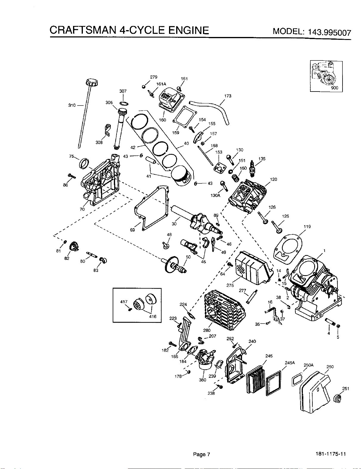
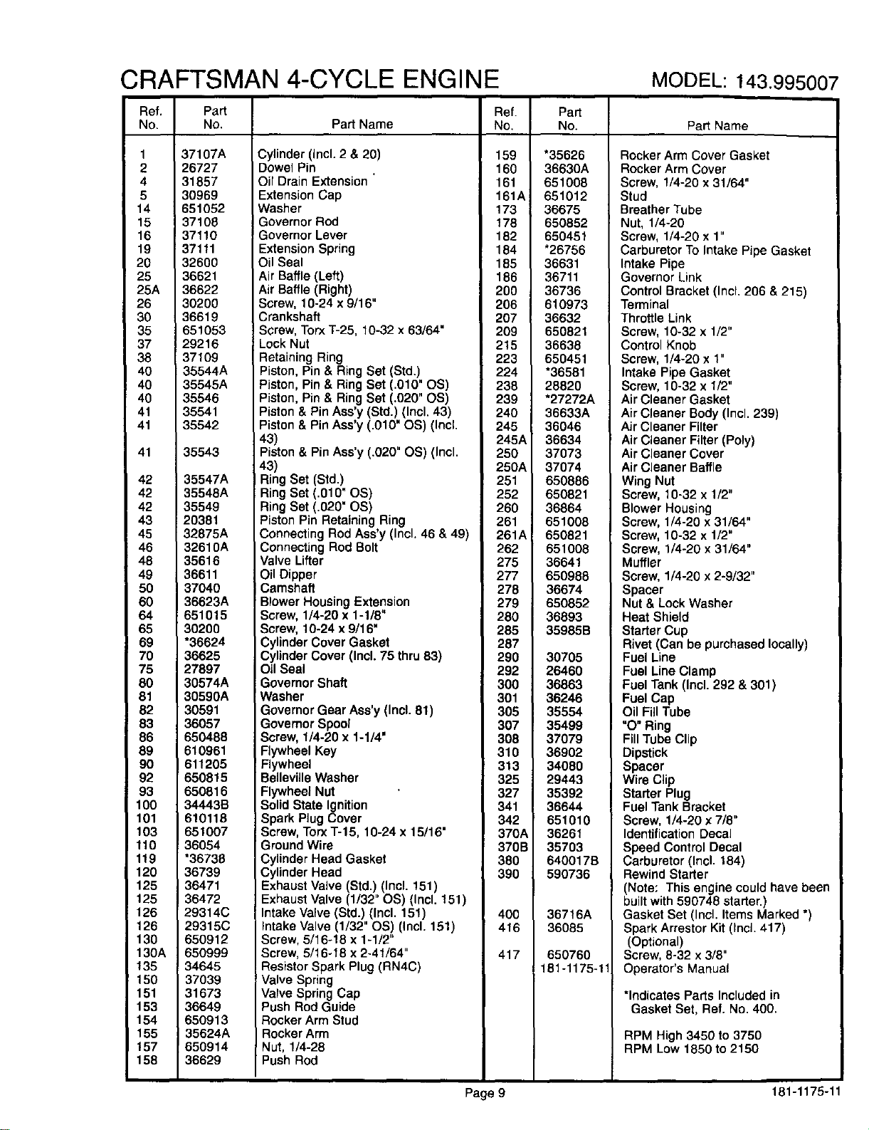
CRAFTSMAN 4-CYCLE ENGINE MODEL:143.995007
310 --
161
173
130
86
s
...-
82 80 45 J
83
J
275
416
185 /
184 •
_ 207 252
135
240
120
126
125
\\
38 2
16
245
---g3o I
119
5
245A
25O
/ 250A /"
Page 7 181-1175-11
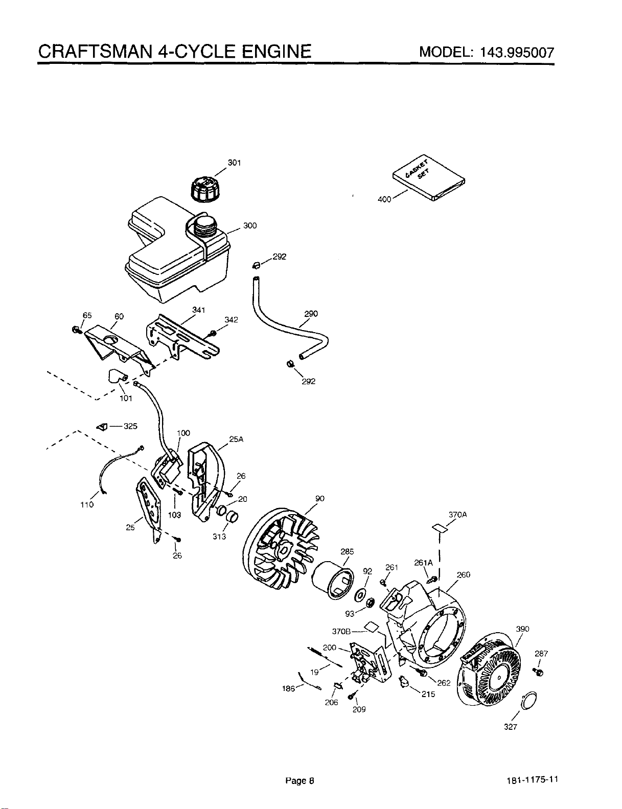
CRAFTSMAN 4-CYCLE ENGINE MODEL:143.995007
301
/
400
65
6O
341
,_.292
-- 325
100
25A
110
313
26
9O
285
261
370A
261A I
26O
_215
39O
/
287
/
©
/
327
Page 8 181-1175-11
CRAFTSMAN 4-CYCLE ENGINE MODEL: 143.995007
Ref. Part
No. No.
1 37107A
2 26727
4 31857
5 30969
14 651052
15 37108
16 37110
19 37111
20 32600
25 36621
25A 36622
26 30200
30 36619
35 651053
37 29216
38 37109
40 _35544A
40 35545A
40 35546
41 35541
41 35542
41
42
42
42
43
45
46
48
49
50
60
64
65
69
70
75
80
81
82
83
86
89
90
92
93
100
101
103
110
119
120
125
125
126
126
130
130A
135
150
151
153
154
155
157
158
35543
35547A
35548A
35549
20381
32875A
32610A
35616
36611
37040
36623A
651015
30200
*36624
36625
27897
30574A
30590A
30591
36057
650488
610961
611205
650815
650816
34443B
610118
651007
36054
*36736
36739
36471
36472
29314C
29315C
650912
650999
34645
37039
31673
36649
650913
35624A
650914
36629
Ref. Part
Part Name No. No.
Cylinder (Incl. 2 & 20) 159
Dowel Pin 160
Oil Drain Extension " 161
Extension Cap 161A
Washer 173
Governor Rod 178
Governor Lever 182
Extension Spring 184
Oil Seal 185
Air Baffle (Left) 186
Air Baffle (Right) 200
Screw, 10-24 x 9/16" 206
Crankshaft 207
Screw, Torx T-25, 10-32 x 63/64" 209
Lock Nut 215
Retaining Ring 223
Piston, Pin & Ring Set (Std.) 224
Piston, Pin & Ring Set (.010" OS) 238
Piston, Pin & Ring Set (.020" OS) 239
Piston & Pin Ass'y (Std.) (Incl. 43) 240
Piston & Pin Ass'y (.010" OS) (Incl. 245
43) 245A
Piston & Pin Ass'y (.020" OS) (Incl. 250
43) 250A
Ring Set (Std.) 251
Ring Set (.010" OS) 252
Ring Set (.020" OS) 260
Piston Pin Retaining Ring 261
Connecting Rod Ass'y (Incl. 46 & 49) 261A
Connecting Rod Bolt 262
Valve Lifter 275
Oil Dipper 277
Camshaft 278
Blower Housing Extension 279
Screw, 1/4-20 x 1-1/8" 280
Screw, 10-24 x 9/16" 285
Cylinder Cover Gasket 287
Cylinder Cover (Incl. 75 thru 83) 290
Oil Seal 292
Governor Shaft 300
Washer 301
Governor Gear Ass'y (Incl. 81) 305
Governor Spool 307
Screw, 1/4-20 x 1-1/4' 308
Flywheel Key 310
Flywheel 313
BellevUle Washer 325
Flywheel Nut 327
Solid State Ignition 341
Spark Plug Cover 342
Screw, Torx T-15, 10-24 x 15/16" 370A
Ground Wire 370B
Cylinder Head Gasket 380
Cylinder Head 390
Exhaust Valve (Std.) (Incl. 151)
Exhaust Valve (1/32" OS) (Incl. 151)
Intake Valve (Std.) (Incl. 151) 400
Intake Valve (1/32" OS) (Incl. 151) 416
Screw, 5/16-18 x 1-1/2"
Screw, 5/16-18 x 2-41/64" 417
Resistor Spark Plug (RN4C)
Valve Spring
Valve Spring Cap
Push Rod Guide
Rocker Arm Stud
Rocker Arm
Nut, 1/4-28
Push Rod
*35626
36630A
651008
651012
36675
650852
650451
*26756
36631
36711
36736
610973
36632
650821
36638
650451
*36581
28820
"27272A
36633A
36046
36634
37073
37074
650886
650821
36864
651008
650821
651008
36641
650988
36674
650852
36893
35985B
30705
26460
36863
36246
35554
35499
37079
36902
34080
29443
35392
36644
651010
36261
35703
640017B
590736
36716A
36085
65076O
181-1175-11
Part Name
Rocker Arm Cover Gasket
Rocker Arm Cover
Screw, 1/4-20 x 31/64"
Stud
Breather Tube
Nut, 1/4-20
Screw, 1/4-20 x 1"
Carburetor To Intake Pipe Gasket
Intake Pipe
Governor Link
Control Bracket (Incl. 206 & 215)
Terminal
Throttle Link
Screw, 10-32 x 1/2"
Control Knob
Screw, 1/4-20 x 1"
Intake Pipe Gasket
Screw, 10-32 x 1/2"
Air Cleaner Gasket
Air Cleaner Body (Incl. 239)
Air Cleaner Filter
Air Cleaner Filter (Poly)
Air Cleaner Cover
Air Cleaner Baffle
Wing Nut
Screw, 10-32 x 1/2"
Blower Housing
Screw, 1/4-20 x 31/64"
Screw, 10-32 x 1/2"
Screw, 1/4-20 x 31/64"
Muffler
Screw, 1/4-20 x 2-9/32"
Spacer
Nut & Lock Washer
Heat Shield
Starter Cup
Rivet (Can be purchased locally)
Fuel Line
Fuel Line Clamp
Fuel Tank (Incl. 292 & 301)
Fuel Cap
Oil Fill Tube
"O" Ring
Fill Tube Clip
Dipstick
Spacer
Wire Clip
Starter Plug
Fuel Tank Bracket
Screw, 1/4-20 x 7/8"
Identification Decal
Speed Control Decal
Carburetor (Incl. 184)
Rewind Starter
(Note: This engine could have been
built with 590748 starter.)
Gasket Set (Incl. Items Marked *)
Spark Arrestor Kit (Incl. 417)
(Optional)
Screw, 8-32 x 3/8"
Operator's Manual
*Indicates Parts Included in
Gasket Set, Ref. No. 400.
RPM High 3450 to 3750
RPM Low 1850 to 2150
Page 9 181-1175-11
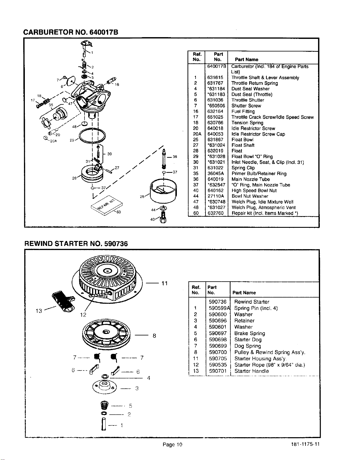
CARBURETOR NO. 640017B
• 3o
Ref. Part
No. No. Part Name
640017B Carburetor (IncL 184 of Engine Parts
List)
1 631615 Throttle Shaft & Lever Assembly
2 631767 Throttle Return Spring
4 "631184 Dust Seal Washer
5 *631183 I Dust Seal (Throttle)
6 631036 Throttle Shutter
7 *650506 Shutter Screw
16 632164 Fuel Fitting
17 651025 Throttle Crack Screw/Idle Speed Screw
18 630766 Tension Spring
20 640018 Idle Restric_or Screw
20A 640053 Idle Restrictor Screw Cap
25 631867 Float Bowl
27 "631024 Float Shaft
28 632019 Float
29 *631028 Float Bowl "O° Ring
30 *631021 Inlet Needle, Seat, & Clip (Incl. 31)
31 631022 Spring Clip
35 36045A Primer Bulb/Retainer Ring
36 640019 Main Nozzle Tube
37 *632547 "O" Ring, Main Nozzle Tube
40 640162 High Speed Bowl Nut
44 27110A Bowl Nut Washer
47 *630748 Welch Plug, Idle Mixture Well
48 *631027 Welch Plug, Atmospheric Vent
60 632760 Repair kit (Incl. Items Marked *)
REWIND STARTER NO. 590736
13
12
7--- 4--7
O--- ?
8
--11
Ref. IPart I
No. No, | Part Name
590736/ Rewind Starter
1 I 590599A_ Spring Pin (Incl. 4)
2 I 590600| Washer
3 I 590696| Retainer
4 I 590601| Washer
5 i 590697| Brake Spring
6 i 590698| Starter Dog
7 I 590699 I Dog Spring
8 I 590700 I Pulley& RewindSpdngAssy.
11 | 590705 Starter Housing Ass'y.
12 I 590535 i Starter Rope (98" x 9/64" dia.)
13 _0 !_.LSta_rter..Ha.nd!e-.................
Page 10 181-1175-11
operator's
manual
MODEL NO. 143.995007
SOLID STATE IGNITION
CAUTION:
Read RULES for
Safe OPERATION
and INSTRUCTIONS
Carefully
How to ORDER Repair Parts
The Model Number can be found on a decal on the blower
housing (See Figure 1). Always mention the Model Number
when requesting service or repair parts for your Craftsman
Engine.
All parts listed herein may be ordered from any SEARS, ROE-
BUCK AND CO, or SEARS CANADA, INC. retail or catalog
store. Ifthe parts you need are not stocked locally, your order
will be electronically transmitted to a Sears Repair Parts Distribu-
tion Center for expedited handling.
WHEN ORDERING REPAIR PARTS, ALWAYS GIVE THE
FOLLOWING INFORMATION AS SHOWN IN THIS LIST.
1. The PART NUMBER
2. The PART DESCRIPTION
3. The MODEL NUMBER
4. The NAME OF ITEM - ENGINE
"Your Sears merchandise has added value when you consider that Sears has
service units nationwide staffed with Sears trained technicians.., professional
technicians specifically trained on Sears products, having the parts, tools and
equipment to insure that we meet our pledge to you ... we service what we sell,"
Sold by SEARS, ROEBUCK AND CO., CHICAGO, IL 60684 U.S.A.
and SEARS CANADA, INC., TORONTO, ONTARIO, CANADA
181-1175-11