Loading ...
Loading ...
Loading ...
10
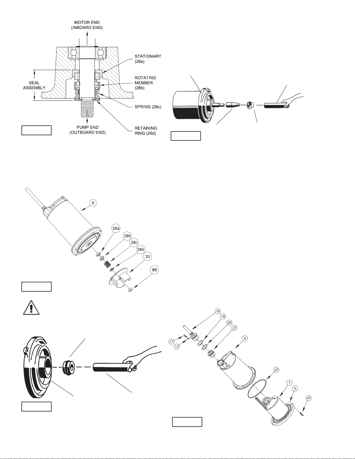
F-3.2) Reassembly:
Clean and oil seal cavities in seal plates (5). Lightly oil (DO
NOT use grease) outer surface of stationary member (28a).
Press stationary member (28a) fi rmly into inner seal plate (5),
using a seal pusher (see parts list - seal tool kit). Nothing but
the seal pusher is to come in contact with seal face (see Figure
8).
Important ! - DO NOT hammer on the seal
pusher- it will damage the seal face.
Make sure the stationary member is in straight. Slide a bullet
(see parts list - seal tool kit) over motor shaft. Lightly oil (DO NOT
use grease) shaft, bullet and inner surface of bellows on rotating
member (28b), see Figure 9. With lapped surface of rotating
member (28b) facing inward toward stationary member, slide
rotating member over bullet and onto shaft, using seal pusher,
until lapped faces of (28a) and (28b) are together (see Figure 8).
It is extremely important to keep seal faces clean during
assembly. Dirt particles lodged between these faces will cause
the seal to leak. Place spring (28c) over shaft and in place on
rotating member (28b), making sure it is seated on retainer and
not cocked or resting on bellows tail. Slide retaining ring (28d)
over shaft and let rest on spring (28c). Replace snap ring (32)
in groove of shaft. Set square-ring (27) in groove on outer seal
plate (29) and place outer seal plate (29) onto inner seal plate
(5). Replace socket head cap screws (64) and torque to 60 in-lbs.
F-4) Motor and Bearing Service:
F-4.1) Disassembly and Inspection:
To examine or replace the motor (7), capacitor (9) and bearing
(25), drain oil from motor as outlined in paragraph F-1.1.
Disassemble volute and impeller as outlined in paragraph F-
2.1 and disassemble shaft seal as outlined in paragraph F-3.1.
Position unit upright, using blocks to avoid resting unit on
shaft. Unscrew cord hex bolts (11) and remove compression
fl ange (16a) and power cord (16). Remove snap ring (19) with
a fl at head screwdriver. Pull the terminal block (21) out of the
housing (6) using a T-bolt or a pair of pliers and a .25-20 screw
in the threads of the terminal block (21). Be sure to leave
slack on the motor leads connected underneath. Use needle
nose pliers to pull each female connector off of the pins on the
FIGURE 7
FIGURE 8
FIGURE 9
FIGURE 10
Stationary Member
(28A) Polished Face Out
Seal Pusher
Seal Plate (5) for L series
and (29) for DS series
FIGURE 6
Motor & Seal Plate
Bullet
Rotating Member
(28B)
Seal Pusher
Loading ...
Loading ...
Loading ...