OUTDOOR
POST LIGHT
1. Pour cement base for the lamp.
2. Place anchor bolts into the cement with the base plate sitting on
top of the cement holding the bolts in proper position. Make sure the
anchor bolts are above the cement sufficiently to clear through the
base when assembled. Make sure the power supply passes through
the center hole of the base plate. (Note: make sure the surface of the
cement is level). After the cement is cured, proceed with the next step.
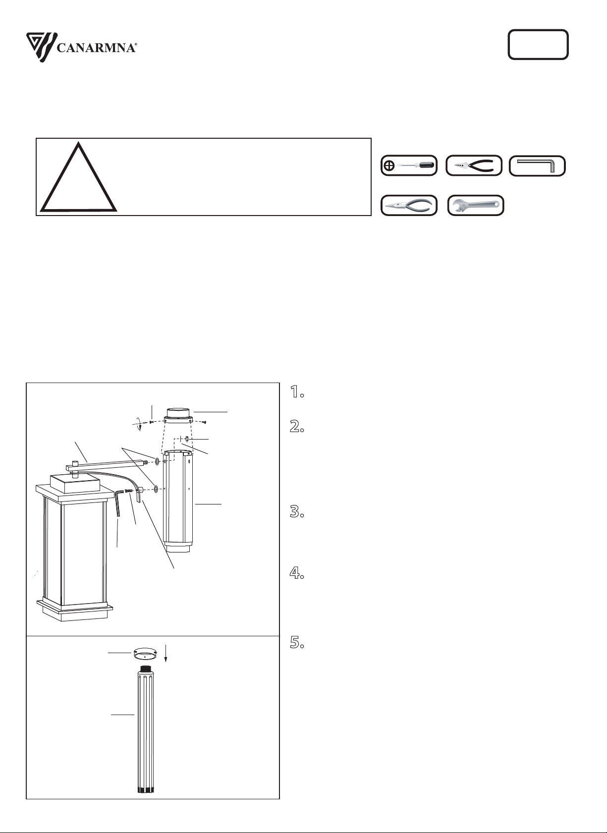
3. Assmble the three arms to the center post using the rubber
gasket, hex nut and lock washer for each of the top arm. Also, tighten
the hexagon screw with rubber washer on each of the bottom arm
with the allen key (not provided).
4. Secure the top cap with the 3 screws.
5. Slide the ring onto the upper post.
IOL475
12/19
1. TURN OFF ELECTRICAL POWER BEFORE STARTING INSTALLATION OF LIGHT FIXTURE.
2. WIRING SUPPLIES AS REQUIRED BY LOCAL ELECTRICAL CODE.
3. THIS PRODUCT MUST BE INSTALLED IN ACCORDANCE WITH THE APPLICABLE INSTALLATION
CODE BY A PERSON FAMILIAR WITH THE CONSTRUCTION AND OPERATION OF THE PRODUCT AND
THE HAZARDS INVOLVED.
4. TO CLEAN THE FIXTURE, TURN OFF THE POWER, WAIT FOR IT TO COOL, AND WIPE THE FIXTURE WITH
A CLEAN, SOFT CLOTH.
NOTE: Product may not look exactly as shown in figures.
Phillips
Screwdriver
Wire Cutters
Pliers Wrench
!
INSTRUCTIONS PERTAINING TO RISK OF FIRE OR INJURY TO PERSONS
READ ALL INSTRUCTIONS
IMPORTANT SAFETY
INSTRUCTIONS
SAVE THESE INSTRUCTIONS
1-2
INSTALLATION:
SAFETY PRECAUTIONS:
1-800-265-1833 (English) / 1-800-567-2513 (French)
Monday through Friday 8:00 AM to 5:00 PM E.S.T.
TOOLS AND MATERIALS REQUIRED:
Questions or Concerns Contact At The Following Phone Numbers Before Returning Product To The Store:
Center
Post
Top Cap
Top Arm
Bottom
Arm
Lock
washer
Hex Nut
Screw
Rubber
Gasket
Upper
Post
Allen key
Hexagon
Screw
Allen
key
Ring
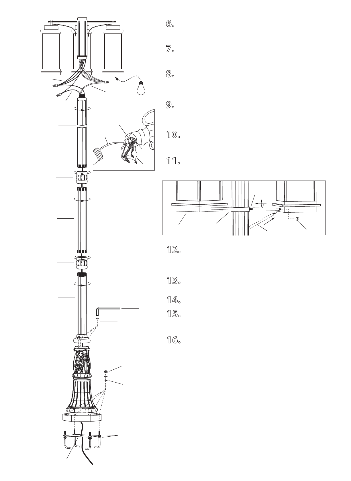
6. Feed the power leads up through the base and bolt the base
to the anchor bolts using locking nuts, anchor bolt nuts and cap
nuts.
7. Feed the power supply through the posts and connectors as
shown. Feed power supply through the cable tie. Tighten the cable
tie so that the power supply tightens against the bar.
8. Connect the power supply to the head assembly. Attach the
black wire to the black wires. Attach the white wire to the white
wires. Ground wire from power supply should be attached to
ground wire from bar inside the head assembly.
9. Once connections of wires are completed, carefully tuck wires
and wire nuts into the center post. Making sure no bare wire (on
the black and white) is visible at the wire nuts.
10. Screw the upper post into the head assembly (be careful
not to twist the wires).
11. Screw the connectors and remaining posts into the upper
post as shown.
12. Line up the ring to the level of the hole at the bottom of the
light head. Insert the rod to the hole of the light head as shown
then screw the other end of the rod to the ring. Tighten the rod to
the light head with the cap nut.
13. Secure the ring on to the upper post by tightening the
other two screws on the ring.
14. Install the remaing rods as previous step.
15. Set the assembled pieces (lower post, middle post, upper
post & head assembly) onto the base by tightening the 3 hexagon
screws with the allen key (not provided).
16. Install the proper bulb type and wattage (not included).
Tel: (613) 342-5424, Fax: (800) 263-4598
2-2
Base Plate
Anchor Bolt
Anchor Bolt Nut
Locking Nut
Base
Power
Cap Nut
Lower
Post
Upper
Post
Middle
Post
White
Black
Ground
Connector
Connector
Hexagon
Screw
Anchor Bolt Nuts
Allen key
Bulb
Ring
Bar
Ground
Head Assembly
Upper
Post
Power
Supply
Cable tie
Ring
Rod
Cap
Nut
Screw
Light Head

1. Verser le ciment dans la base.
2. Posez les boulons dans le ciment et reposez la plaque de la
base sur le dessus tenant ainsi les boulons en position.
Assurez-vous que les boulons dÈpassent suffisament le ciment
pour passer en travers de la base lorsque le tout sera assemblé.
Assurez-vous que le courant passe en travers du trou au centre
de la plaque de la base. (N.B.: Assurrez-vous que la surface du
ciment en bien de niveau). Après que le ciment ait durci
quelque peu, procédez aux étapes suivantes.
3. Assemblez les trois bras au poteau du centre à l’aide du
joint d’étanchéité en caoutchouc, l’écrou et la rondelle de
blocage pour chacun des bras supérieurs. Serrez également la
vis hexagonal et la rondelle en caoutchouc sur chacun des bras
du dessous à l’aide d’une clé allen (non incluse).
4. Posez le capuchon du haut à l'aide des 3 vis.
5. Glissez l'anneau sur le poteau supėrieur.
1-2
ECLAIRAGE
EXTERIEUR
1. FERMEZ LE COURANT AU DISJONCTEUR AVANT DE DEBUTER L’INSTALLATION DE LA FIXTURE.
2. FOURNITURES ÉLECTRIQUES TELLES QUE PRESCRITES PAR LES NORMES LOCALES.
3. CE PRODUIT DOIT ÊTRE INSTALLÉ SELON LE CODE D’INSTALLATION PERTINENT, PAR UNE PERSONNE
QUI CONNAIT BIEN LE PRODUIT ET SON FONCTIONNEMENT AINSI QUE LES RISQUES INHÉRENTS.
4. POUR NETTOYER LE LUMINAIRE, L’ÉTEINDRE, ATTENDRE QU’IL SOIT FROID, PUIS LE NETTOYER
AVEC LINGE PROPRE ET DOUX.
N.B.: Peut différer de illustration.
Tournevis A
Phillips
Coupeur De Fils
Pinces
Clef
!
INSTRUCTIONS CONCERNANT LE RISQUE
D’INCENDIES OU LES DOMMAGES CORPORELS
LISEZ TOUTES LES INSTRUCTIONS
INSTRUCTIONS DE SÛRETÉ
IMPORTANTES
GARDEZ CES INSTRUCTIONS
Poteau
Du Haut
Rondelle
De Blocage
Joint
D’étanchéité
Écrou
Hexagonal
Bras
Inférieur
Bras
Supérieurs
Poteau
Du Centre
IOL475
12/19
Pour Toutes Questions Ou Commentaires, Veuillez Nous Contacter Avant De Retourner Le Produit Au Détaillant:
1-800-265-1833 (Anglais) / 1-800-567-2513 (Français)
Du lundi au vendredi 8 :00am à 5 :00pm E.S.T
INSTALLATION:
MISE EN GARDE:
OUTILS ET MATERIAUX REQUIS:
Capuchon
Vis
Clé
Allen
Clé Allen
Vis
Hexagonales
Anneau

6. Faufilez les fils de courant en travers de la base et fixez la
base aux boulons d’ancrage avec les écrous de blocage, les écrous
de boulon et les écrous à capuchon.
7. Faufilez le fils de courant en travers du poteau et des
connecteurs tel qu’illustré. Faufilez la source de courant en travers
de l'attache en nylon. Serrez l'attache afin que le cable soit serré
contre la barre.
8. Branchez le courant à la tête. Posez le fil noir au fils noirs. Posez
le fil blanc au fils blancs.Le fil de la mise à terre de la source de
courant devrait Ítre attaché au fil de mise à terre sur la barre situé à
l'intérieur de la tête.
9. Une fois les connexions de fils terminées, poussez
soigneusement les fils et les écrous de connexions dans le poteau
du centre. Assurez-vous qu'aucun fil dénudé
(noir ou blanc) est visible.
10. Vissez le poteau du haut à la tête. (Attention de ne pas
tordre les fils).
11. Vissez les connecteurs ainsi que les poteaux dans le poteau
supérieur tel qu’illustré.
12. Alignez l'anneau au niveau de l'ouverture situėe sur le
dessous de la tête du luminaire. Insėrez la tige dans cette
ouverture tel qu'illustré puis vissez l'autre extrėmité de la tige à
l'anneau. Vissez la tige au luminaire avec l'écrou borgne.
13. Posez l'anneau sur le poteau supérieur en serrant les deux
autres vis de l'anneau.
14. Installez les autres tiges en suivant les mêmes ėtapes.
15. Posez les pièces assemblées (poteau inférieur, poteau du
centre , poteau supérieur et tête de moteur) sur la base et serrez en
place à l’aide des 3 écrous hexagonales et d’une clé allen (non
incluse).
16.
Posez l'ampoule de type et de wattage requis (en sus).
Écrou de
Blocage
2-2
Ecrous De
Boulons
D’ancrage
Ecrous De Boulons
D’ancrage
Boulons
D’ancrage
PH: (450) 665-2535, FX: (450) 665-0910
Poteau
Inférieur
Poteau
Du Haut
Courant
Plaque De
La Base
Blanc
Noir
Ampoule
Base
Poteau
du centre
Connecteur
Connecteur
Clé Allen
Vis
Hexagonales
Anneau
Anneau
Barre
Poteau
Supérieur
Source De
Courant
Attache En
Nylon
Mise A
Terre
Tête
Mise A
Terre
Écrou à tête
Écrou
à tête
Vis
Tête du
luminaire
Tige