Loading ...
Loading ...
Loading ...

–
7
–
6. ASSEMBLING THE
PLASMA CUTTER
6.1 CONNECTION TO THE POWER
SUPPLY
Make sure the power supply information on the product’s
rating plate is compatible with the power supply you
intend to connect it to.
A suitable plug must be fitted by a qualified
electrician.
This product’s wiring has insulation stripped in
preparation for wiring a 32A plug (not supplied).
It is designed for connection to a 32 amp power supply
rated at 230V AC.
Because it is constructed mostly of metal parts, it is a
Class 1 machine; meaning, it must have an earth
connection in the power supply. This is to prevent
electrocution in the event of a failure.
Note: Remove the plug from the socket before carrying
out adjustment, servicing or maintenance.
Check that the electrical supply delivers the voltage and
frequency corresponding to the product and that it is
fitted with a delayed fuse suited to the maximum
delivered rated current.
Note: This product has been set to the highest voltage
at the factory.
6.2 CONNECTION TO THE AIR SUPPLY
– FIGS.1 – 3
This product has been designed to be operated in
conjunction with a compressed air supply.
Note: Do not use the product in conjunction with oxygen,
or any other gasses.
− Using an appropriate hose and fittings combination,
connect the product to an air supply that adequately
meets the demands of the product’s specifications.
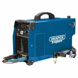
Note: Draper Stock No.70058 is supplied with an
integrated air regulator and moisture trap.
1 – Stock No.70058 shown.
FIG.
2 – Stock No.70066 shown.
FIG.
3 – Recommended air supply set up.
FIG.
6.3 CONNECTING THE EARTH
CLAMP – FIG.4
− With the lug on the pin at top, push the connector
fully into the port (8) then turned clockwise 180° to
lock hand tight only.
4 – Stock No.70066 shown.
FIG.
6.4 ATTACH THE TORCH – FIG.5
− To connect the torch trigger connector (6.1), align the
2 pins and push to fit, then secure using the outer
ring (6.2) screwing it onto trigger port (6).
− Remove the threaded knob of the pilot arc ingnitor
(7)and place the terminal of the red lead over the
post, then replace the knob and tighten.
y
Quick coupler
Water separation
Nipple
Regulator
Drain daily
Air suppl
Air line hose
(8)
(8.1)
Loading ...
Loading ...
Loading ...