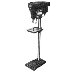
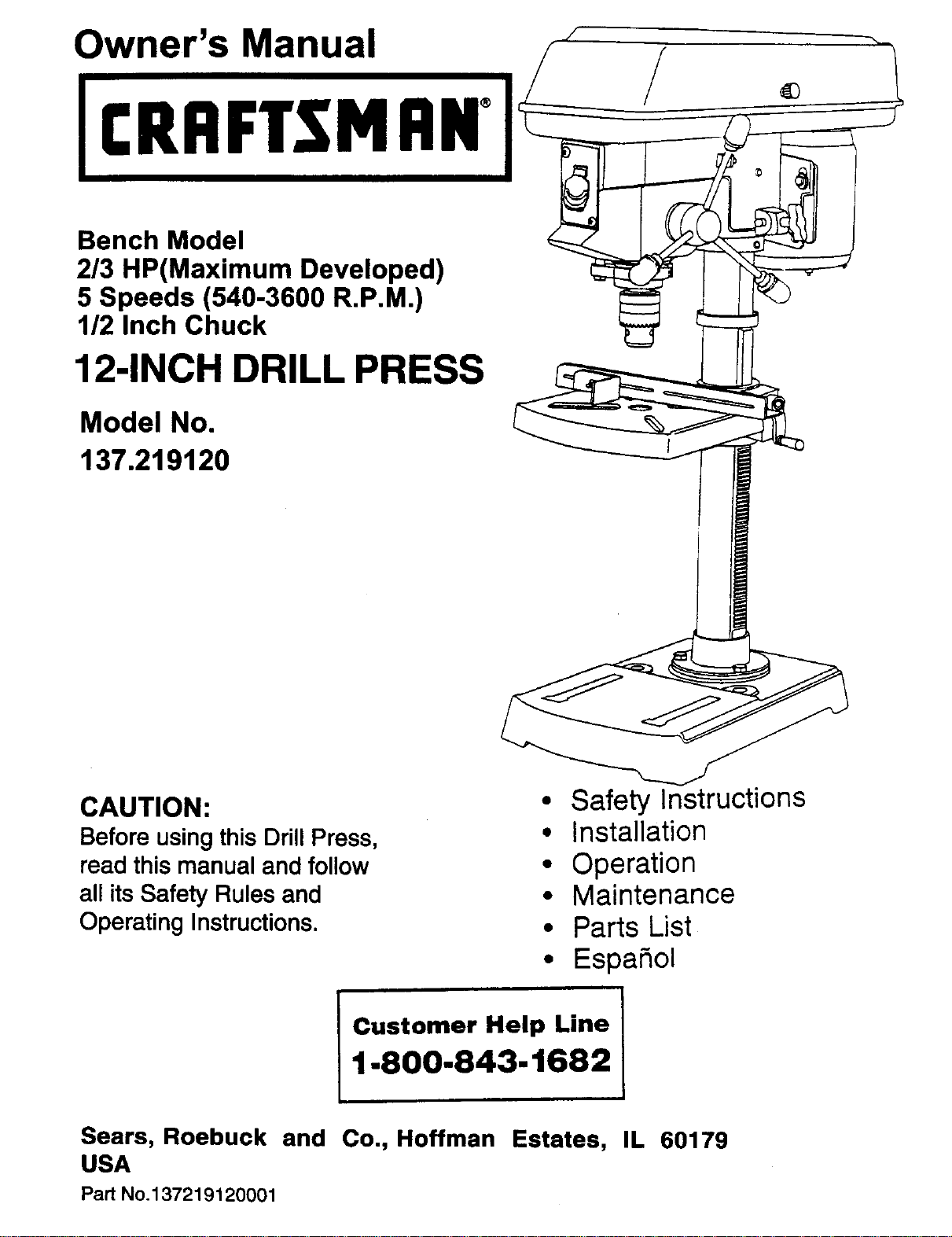
Owner's Manual
CRRFTSMRN°
Bench Model
2/3 HP(Maximum Developed)
5 Speeds (540-3600 R,P.M.)
1/2 Inch Chuck
12-INCH DRILL PRESS
Model No.
137.219120
CAUTION:
Before usingthis Drill Press,
read this manual and follow
all its Safety Rules and
Operating Instructions.
• Safety Instructions
• Installation
• Operation
• Maintenance
• Parts List
• Espa_ol
Customer Help Line
1.800-843-1682
Sears, Roebuck and Co., Hoffman Estates, IL 60179
USA
Part No.137219120001
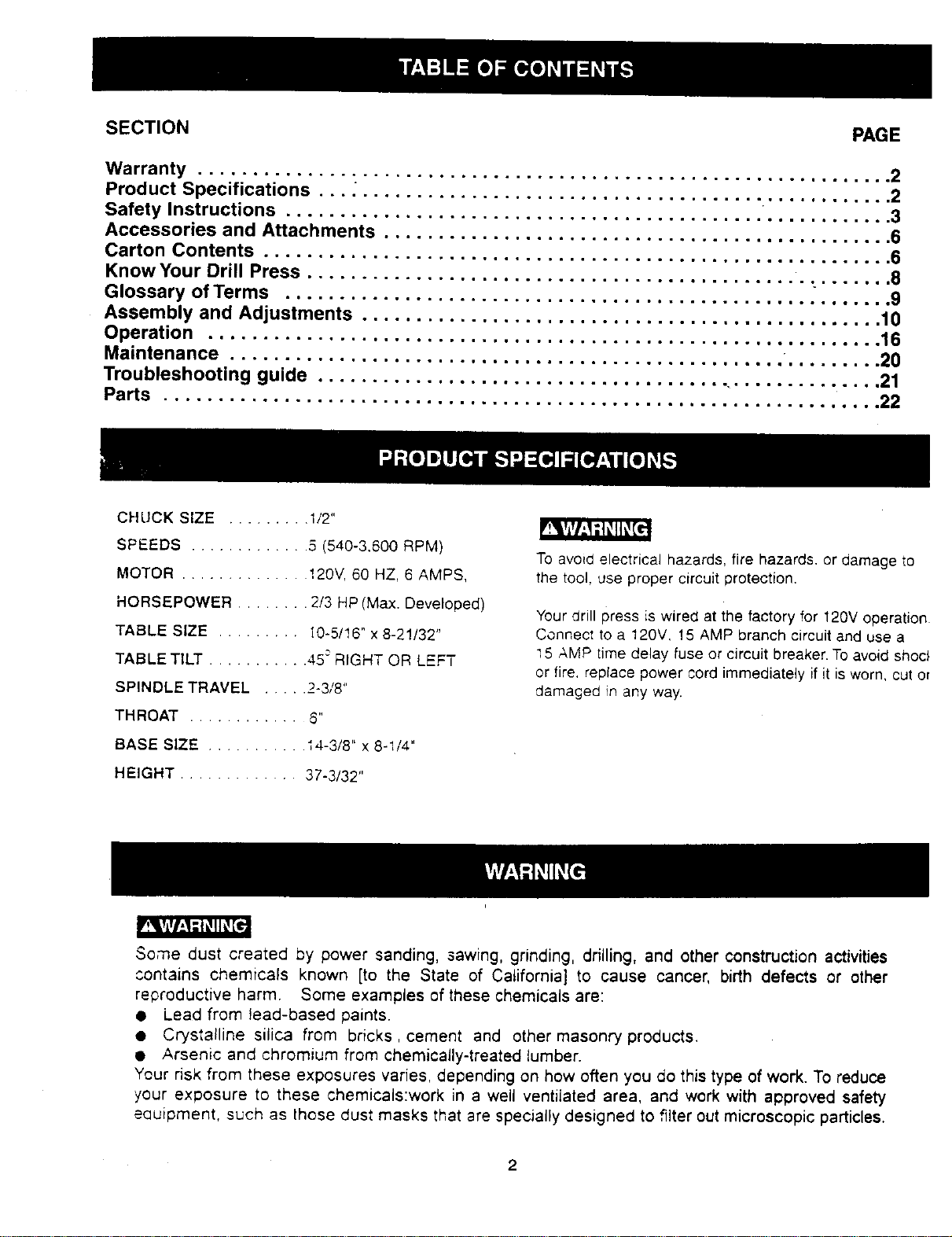
SECTION PAGE
Warranty ...........................
Product Specifications ................
Safety Instructions ...................
Accessories and Attachments ..........
Carton Contents .....................
Know Your Drill Press .................
Glossary of Terms ...................
Assembly and Adjustments ............
Operation ...............................................
Maintenance .............................................
Troubleshooting guide .....................................
Parts ...................................................
°.,o.,o,,°,..=,,,,=,
.ooo,.oooo°o,.,,o°,o
°o°oo.o.o°°°.°°o°°°o
,°°o°oo°°°,°o,°o,Jo°
°oo°,°°°°o.oo°o°o,°o
o°o°°oo°°°,°..oo°,l,
,Jo°,°°oo°°o°,oo°°o,
=o°,l,°°,ooill,,,mlm
°n =°oJl°°l°
°° °°°°=l =°
°° OI°°°Q °°
°° =°_=° °l
°° °°=°° ng
°° =°'°_°
°° lloo°
Qm °ll==
oo OOJ°°
,gql=,°
= ,OOo°,,
11 mi,w,a
..2
..2
,,3
.,6
°,6
oo 118
• • m i_
...10
.... 16
.... 20
.... 21
.... 22
CHUCK SIZE ......... I/2"
SPEEDS ............. 5 (540-3,600 RPM)
MOTOR .............. !20V, 50 HZ, 6 AMPS,
HORSEPOWER ........ 2/3 HP (Max. Develo_3ed)
TABLE SIZE ......... 10-5/t6" x 8-2!/32"
TABLE TILT ........... 45oRIGHT OR LEFT
SPINDLE TRAVEL ..... 2-3/8"
THROAT ............ _"
BASE SIZE ........... 14-3/8" x 8-1/4"
HEIGHT ............. 37-3/32"
To avoid electrical hazards, fire hazards, or damage to
the tool. use proper circuit protection.
Your drill press is wired at the factory for 120V operation
Connect to a 120V, !5 AMP branch circuit and use a
15 AMP time delay fuse or circuit breaker. To avoid shod
or fire, replace power cord immediately if it is worn, cut or
damaged in any way.
Some dust created by power sanding, saw=ng, grinding, drilling, and other construction activities
contains chemicals known [to the State of California] to cause cancer, birth defects or other
reproductive harm. Some examples of these chemicals are:
• Lead from lead-based paints.
• Crystalline silica from bricks, cement and other masonry products.
• Arsenic and chromium from chemically-treated lumber.
Your risk from these exposures varies, depending on how often you do this type of work. To reduce
your exposure to these chemicals:work in a well ventilated area, and work with approved safety
eauipment, such as those dust masks that are specially designed to ,filter out microscopic particles.
2
GENERAL SAFETY INSTRUCTIONS 14.
BEFORE USING THE DRILL PRESS
Safety is a combination of common sense, staying alert
and knowing how to use your drill press. 15.
REMOVE ADJUSTING KEYS AND WRENCHES.
From the habit of checking to see that keys and
adjusting wrenches are removed from the tool before
turning "ON".
NEVER LEAVE TOOL RUNNING UNATTENDED.
TURNTHE POWER "OFF". Don't leave the tool until
it comes to a complete stop.
To avoid mistakes that could cause serious injury, do not 16. NEVER STAND ON TOOL. Serious injui'y could occur
plug the drillpress in until you have read and understood ifthe toolistipped or ifthe cutting toolis unintentionally
the following: contacted.
1. READ and become familiar with this entire instruction
manual. LEARN the tool'sapplications, limitations, and
possible hazards,
2. KEEP GUARDS IN PLACE and in working order.
3. DON'T USE IN A DANGEROUS ENVIRONMENT.
Don't use power tools in damp or wet locations, or
expose them to rain. Keep work area well lighted.
4. DO NOT use power toolsin the presence offlammable
liquids or gases.
5. KEEP WORK AREA CLEAN. Cluttered areas and
benches invite accidents.
6. KEEP CHILDREN AWAY.All visitorsshould be kept at
a safe distance from the work area.
7. DON'T FORCE THE TOOL. It will do the job better
and safer at the rate for which it was designed.
8. USE THE RIGHT TOOL. Don't force tool or the
attachment to do a job for which it was not designed.
9, WEAR PROPER APPAREL. DO NOT wear loose
clothing, gloves, neckties, rings, bracelets, or other
jewelry which may get caught in moving parts.
Nonslip footwear is recommended. Wear protective
hair covering to contain long hair.
17. DON'T OVERREACH. Keep proper footing and
balance at all times.
18. MAINTAIN TOOLS WITH CARE. Keep tools sharp
and clean for best and safest performance. Follow
instructionsfor lubricating and changing accessories.
19. CHECK FOR DAMAGED PARTS. Before further use of
the tool, a guard or other part that is damaged should
be carefully checked to determine that it will operate
properly and perform its intended function. Check for
alignment of movingparts, binding of moving parts,
breakage of parts, mounting,and any otherconditions
that may affect itsoperation.A guard or other part that
is damaged should be properly repaired or replaced.
20. MAKE WORKSHOP KID PROOF with padlocks, master
switches, or by removing starter keys.
21. DO NOT operate the tool if you are under the influence
of any drugs, alcohol or medication that could affect
your ability to use the tool properly.
22.
Dust generated from certain materials can be
hazardous to your health. Always operate the drill
press in a well-ventilated area and provide for proper
dust removal. Use dust collection systems whenever
possible.
10. WEAR A FACE MASK OR DUST MASK.
Drilling operation produces dust.
11. DISCONNECTTOOLS before servicing, and when
changing accessories, such as blades, bits, cutters,
and the like.
12. REDUCETHE RISK OF UNINTENTIONAL STARTING.
Make sure the switch is in "OFF" position before
plugging in.
13. USE RECOMMENDED ACCESSORIES. Consult the
owner's manual for the recommended accessories.
The use of improper accessories may cause risk of
injury to persons.
23. ALWAYS WEAR EYE
PROTECTION. Any drill press
can throw foreign objects into
the eyes which could cause
permanent eye damage.
ALWAYS wear Safety Goggles
(not glasses) that comply with
ANSI safety standard Z87.1. Everyday eyeglasses
have only impact-resistant lenses. They ARE NOT
safety glasses. Safety Goggles are available at Sears.
NOTE: Glasses or goggles not in compliance with
ANSI Z87.1 couldseriously hurt you when they break.
SAVE THESE INSTRUCTIONS
3
SPECIFIC SAFETY INSTRUCTIONS
FOR THE DRILL PRESS
For your own safety, do not try to use your drill press
or plug it in untilit is completely assembled and installed
according to the instructions, and until you have read and
understood this instruction manual:
1. YOUR DRILL PRESS MUST BE BOLTED securely"
to a workbench. In addition, if there is any tendency
for your drill press to move during certain operations,
bolt the workbench to the floor.
14.
15.
16.
17.
18.
2. THIS DRILL PRESS is intended for use in dry
conditions, indoor use only.
19.
3.
WEAR EYE PROTECTION. USE face or dust mask
along with safety goggles if drilling operation is dusty.
USE ear protectors,especially during extended periods
of operation.
4. DO NOT wear gloves, neckties, or loose clothing.
5. DO NOT try to drill material too small to be securely
held.
20.
21.
6. ALWAYS keep hands out of the path of a drill bit.
Avoid awkward hand positions where a sudden slip
could cause your hand to move into the drill bit. 22.
DO NOT install ol use any drill bit that exceeds
!75 mm (7") in length or extends 150 mm (6") below
the chuck jaws. They can suddenly bend outward or
break.
7.
8. DO NOT USE wire wheels, muter bits, shaper cutters,
circle (fly) cutters, or rotary planers on this drill press.
23.
24.
9. WHEN cutting a large piece of material make sure it
is fully supported at the table height.
10. OO NOT perform any operation freehand. ALWAYS 25.
hold the workpiece firmly against the table so it will
not rock or twist. Use clamps or a vise for unstable
workpieces.
11. MAKE SURE there are no nails or foreign objects in 26.
the part of the workpiece to be drilled.
27.
12. CLAMP WORKPIECE OR BRACE against the left
side of the column to prevent rotation. If it istoo short
or the table is tilted, clamp solidlyto the table and
use the fence provided.
SECURE WORK. Use clamps or a vise to hold the
work when practical. It's safer than using your hand
and it frees both hands to operate tool.
WHEN using a drill press vise, always fasten to the
table.
MAKE SURE all clamps and locks are firmly
tightened before drilling.
SECURELY LOCK THE HEAD and table support to
the column, and the table to the table support before
operating the drill press.
NEVER turn your drill press on before clearing the
table of all objects (tools, scraps of wood, etc.)
BEFORE STARTING the operation, jog the motor
switch to make sure the drill bit does not wobble or
vibrate.
LETTHE SPINDLE REACH FULL SPEED before
starting to drill. If yourdrill press makes an unfamiliar
noise or if it vibrates excessively, stop immediately,
turn the drill press offand unplug.Do not restart until
the problem is corrected.
DO NOT perform layout assembly or set up work on
the table while the drill press is in operation.
USE RECOMMENDED SPEED for drillaccessory and
workpiecematerial. SEE INSTRUCTIONS that come
withthe accessory.
WHEN DRILLING large diameter holes, clamp the
workpiece firmly to the table. Otherwise, the bit may
grab and spin the workpiece at high speed. DO NOT
USE fly cutters or multiple-part hole cutters, as they
can come apart or become unbalanced in use.
MAKE SURE the spindle has come to a complete
stop before touching the workpiece.
TO AVOID INJURY from accidental starting, always
turnthe switch "OFF" and unplugthe drillpress before
installing or removing any accessory or attachment
or making any adjustment.
KEEP GUARDS IN PLACE and in working order.
USE ONLY SELF-EJECTING TYPE CHUCK KEY as
provided with the drill press.
13. IFTHE WORKPIECE overhangs the table such that
it will fall or tip if not held, clamp itto the table or
provide auxiliary support.
SAVE THESE INSTRUCTIONS
4
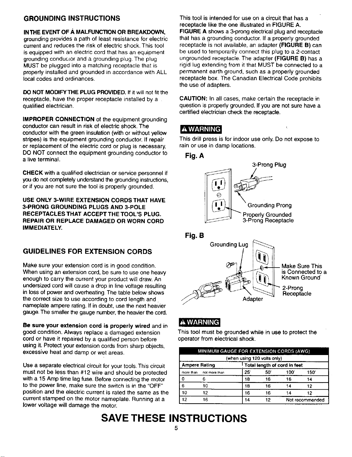
GROUNDINGINSTRUCTIONS
INTHE EVENT OF A MALFUNCTION OR BREAKDOWN,
groundingprovides a path of least resistance for electric
current and reduces the risk of electric shock. This tool
is equipped with an electric cord that has an equipment
grounding conductor and a grounding plug. The plug
MUST be plugged into a matching receptacle that is
properly installed and grounded in accordance with ALL
local codes and ordinances.
DO NOT MODIFYTHE PLUG PROVIDED. If itwill not fit the
receptacle, have the proper receptacle installed by a
qualified electrician.
IMPROPER CONNECTION of the equipment grounding
conductor can result in risk of electric shock. The
conductor with the green insulation(with or without yellow
stripes) is the equipment grounding conductor. If repair
or replacement of the electric cord or plug is necessary,
DO NOT connect the equipment grounding conductor to
a live terminal.
CHECK with a qualified electrician or service personnel if
youdo notcompletelyunderstandthegroundinginstructions,
or if you are not sure the tool is properly grounded.
USE ONLY 3-WIRE EXTENSION CORDS THAT HAVE
3-PRONG GROUNDING PLUGS AND 3-POLE
RECEPTACLES THAT ACCEPT THE TOOL'S PLUG.
REPAIR OR REPLACE DAMAGED OR WORN CORD
IMMEDIATELY.
GUIDELINES FOR EXTENSION CORDS
Make sure your extension cord is in good condition.
When using an extension cord, be sure to use one heavy
enough to carry the current your product will draw. An
undersized cord will cause a drop in line voltage resulting
in loss of power and overheating. The table below shows
the correct size to use according to cord length and.
nameplate ampere rating. If in doubt, use the next heavier
gauge. The smaller the gauge number,the heavier the cord.
This tool is intended for use on a circuit that has a
receptacle like the one illustrated in FIGURE A.
FIGURE A shows a 3-prong electrical plug and receptacle
that has a grounding conductor. If a properly grounded
receptacle is not available, an adapter (FIGURE B) can
be used to temporarily connect this plug to a 2-contact
ungrounded receptacle. The adapter (FIGURE B) has a
rigid lug extending from it that MUST be connected to a
permanent earth ground, such as a properly grounded
receptacle box. The Canadian Electrical Code prohibits
the use of adapters.
CAUTION: tn all cases, make certain the receptacle in
question is properly grounded. If you are not sure have a
certified electrician check the receptacle.
This drill press is for indoor use only. Do not expose to
rain or use in damp locations.
Fig. A
3-Prong Plug
)., Ground,n_ Prong
_- _ Properly Grounded
/
3-Prong Receptacle
Fig. B
Grounding Lug
Adapter
/
-- Make Sure This
is Connected to a
Known Ground
"" 2-Prong
Receptacle
Be sure your extension cord is properly wired and in
good condition. Always replace a damaged extension
cord or have it repaired by a qualified person before
using it. Protect your extension cordsfrom sharp objects,
excessive heat and damp or wet areas.
viII_ Iht,l l j Ltl[_*f:ll[t1:11 ;[O] :1 [:l:a I :ll_I_',1Ill _.[l(e] :| e_.11r__ll,t,vl.
Use a separate electrical circuit for your tools. This circuit
must not be less than #12 wire and should be protected
with a 15 Amp time lag fuse. Before connectingthe motor
to the power line, make sure the switch is in the "OFF"
position and the electric current is rated the same as the
current stamped on the motor nameplate. Running at a
Jowervoltage will damage the motor.
This tool must be grounded while in use to protect the
operator from electrical shock.
(when using 120 volts only)
Ampere Rating I Total length of cord in feet
morethan notmorethan 25' 50' 100' 150'
0 6 18 16 16 14
6 10 18 16 14 12
10 12 16 16 14 12
12 16 14 12 Not recommended
SAVE THESE INSTRUCTIONS
5
AVAILABLE ACCESSORIES
Use only accessories recommended for this drill press.
Follow instructions that accompany accessories. Use of
improper accessories may cause hazards.
T!Ylv/_,1t,:l_ll_,[_
Visit your Sears Hardware Department or see the Sears
Power and Hand Tool Catalog for the following
accessories:
Drill bits
• Hold-Down and Guide
Drill Press Vises
• Clamping Kit
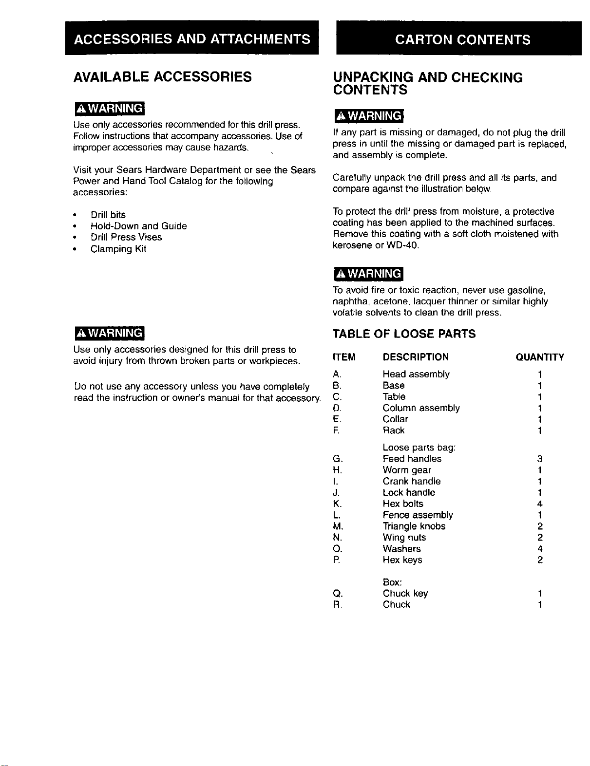
UNPACKING AND CHECKING
CONTENTS
If any part is missing or damaged, do not plug the drill
press in until the missing or damaged part is replaced,
and assembly is complete.
Carefully unpack the drill press and all its parts, and
compare against the illustration below.
To protect the drill press from moisture, a protective
coating has been applied to the machined surfaces.
Remove this coating with a soft cloth moistened with
kerosene or WD-40.
Use only accessories designed for this drill press to
avoid injury from thrown broken parts or workpieces.
Do not use any accessory unless you have completely
read the instruction or owner's manual for that accessory.
To avoid fire or toxic reaction, never use gasoline,
naphtha, acetone, lacquer thinner or similar highly
volatile solvents to clean the drill press.
TABLE OF LOOSE PARTS
ITEM DESCRIPTION QUANTITY
A. Head assembly
B. Base
C. Table
D. Column assembly
E. Collar
F. Rack
Loose parts bag:
G. Feed handles
H. Worm gear
I. Crank handle
J. Lock handle
K. Hex bolts
L. Fence assembly
M. Triangle knobs
N. Wing nuts
O. Washers
P. Hex keys
1
1
1
1
1
1
3
1
1
1
4
1
2
2
4
2
Box:
Q. Chuck key
R. Chuck
F
G H I J K
L
M N 0
P
Q R
7
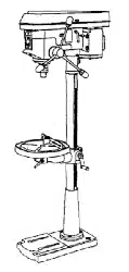
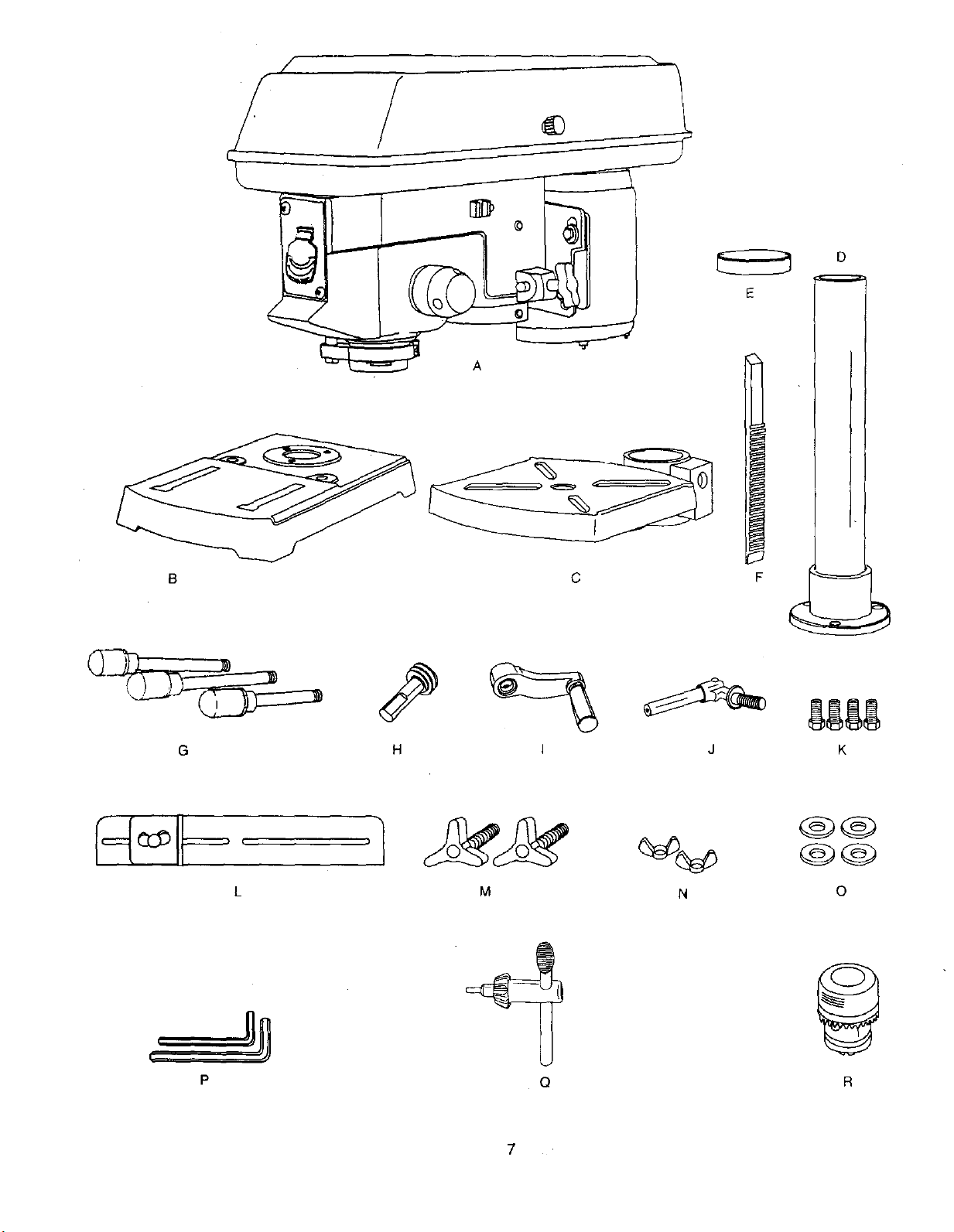
Depth scale stop nuts Depth scale
pointer
Cord clamp
Spindle Motor
pulley pulley
Belt
tension
knob
Feed spring
Column collar
Bevel scale
Table support
Support lock handle Base
Bevel lock
Fence end_
, rod
Depth stop Cover
/
Table
I
Head lock
/ screw
( _.
;tor
elt
Head lock
screw
----_Table crank
handle
Rack
Fence backstop
Column support
BASE- Supports the drill press. For additional stability,
holes are provided in the base to bolt the drill press to
the floor.(See "Specific Safety Instructions for Drill Presses".)
BACKUP MATERIAL - A piece of scrap wood placed
between the workpiece and table. The backup board
prevents wood in the workpiece from splintering when the
drill passes through the backside of the workpiece. It also
prevents drilling into the table top.
BELT GUARD ASSEMBLY - Covers the pulleys and belt
during operation of the ddll press.
BELT TENSION - Refer to the "Assembly" Section,
"Installing and Tensioning Belt."
BELT TENSION KNOB - Tightening the knob locks
the motor bracket support maintaining correct belt distance
and tension.
BEVEL SCALE - Shows the degree of table tilt for bevel
operations.The scale is mounted on the side of the arm.
CHUCK - Holds the drill bit or other recommended
accessory to perform desired operations.
CHUCK KEY -A self-ejecting chuck key which will pop
out of the chuck when you let go of it. This action is
designed to help prevent throwing of the chuck key from
the chuck when the power isturned "ON". Do not use
any other key as a substitute;order a new one ifdamaged
or lost.
COLUMN - Connects the head, table, and base on a
one-piece tube for easy alignment and movement.
COLUMN COLLAR - Holds the rack to the column.
Rack remains movable in the collar to permit table
support movements.
COLUMN SUPPORT - Supports the column, guides the
rack and provides mounting holes for column to base.
DEPTH SCALE - Indicates depth of hole being drillecl
DEPTH SCALE POINTER - Indicates the drilling depth
by pointing to the depth scale.
DEPTH SCALE STOP NUTS - Locks the depth scale to
selected depth.
DRILL ON/OFF SWITCH - Has locking feature. This
feature is intended to help prevent unauthorized and
possible hazardous use by children and others.Insert the
key into the switch to turn the drill press on.
DRILLING SPEED - Changed by placing the belt in any
of the steps (grooves) in the pulleys. See the Spindle
Speed Chart inside the belt guard.
FEED HANDLE - Moves the chuck up or down. If
necessary, one or two of the handles may be removed
whenever the workpiece is of such unusual shape that it
interferes with the handles.
FENCE - Attaches to the table to align the workpiece or
for fast repetitive drilling.Removable. Remove fence when
it interferes with other drillpress accessories.
HEAD LOCKS -Locks the head to the column. ALWAYS
lock the head in place while operating the drill press.
RACK - Combines with gear mechanism to provide easy
elevation of the table by the hand operated table crank.
REVOLUTION PER MINUTE (R.P.M.) - The number of
turns completed by a spinning object in one minute.
SPINDLE SPEED -The R.P.M. of the spindle.
SPRING CAP - Adjusts quill spring tension.
TABLE - Provides working surface to support workpiece.
TABLE BEVEL LOCK - Locks the table inany position
from 0°- 45°.
TABLE CRANK HANDLE - Elevates and lowers table.
Turn clockwiseto elevate table. Support lock must be
released before operating crank.
TABLE SUPPORT LOCK -Tightening locks the table
support to the column. Always have it locked in place
while operating the drill press.
TABLE SUPPORT - Rides on the column to support the
table.
WORKPIECE - Material being drilled.
DRILL BIT - The cuttingtool used in the drill press to
make holes in a workpiece.
ASSEMBLY INSTRUCTIONS
For your own safety, never connect plug to power source
outlet until all assembly and adjustment steps are
completed, and you have read and understood the safety
and operating instructions.
Slotted screwdriver
Combination wrench
L I ] T_I I I I I I I I
Framing square
8"& 10"Adjustable wrenches
Combination square
Socket wrench
with23 mm. socket
TABLE TO COLUMN ASSEMBLY (FIG. B THROUGH F)
1. Locate the worm gear, table crank, and table support
lock handle from the loose parts bag.
2. Insert the worm gear (1) into the table crank handle
hole (2) from inside the table support (3). Make sure
the worm gear (1) meshes with the inside gear.
3. Insert the table support lock handle (4) into the hole
at the rear of the table support. Tighten.
NOTE: Table removed from support in illustrationfor
clarity.
Fig. B _ 1
4. Place the rack (5) in position inside the table support(3),
making sure the worm gear (1) on the inside of the
table support is engaged with the teeth of the rack.
The Drill Press is very heavy and MUST be lifted with the
help of 2 PEOPLE OR MORE, to safely assemble it.
COLUMN SUPPORTTO BASE (FIG. A)
1. Position base (1) on floor.
2. Place column (2) on base, aligningholesin column
support with holes in base.
3. Locate four long hex bolts (3) from loose parts bag.
4. Place a bolt in each hole through the column
support and the base. Tighten with an edjust_ble
wrench.
Fig. A
Fig. C
3 !
2
,
6.
Slide the table support assembly with the rack (3,5)
together onto the column.
Engage the bottom of the rack (6) with the lip of the
column support (6). Tighten the support lock
handle (4) to lock the table support assembly to the
column.
Fig. D
8. Install the table crank handle (9) to the worm gear
shaft (1) on the side of the table support (3).
9. Line up the fiat side ofthe shaftwith the set screw (10)
in the crank handle and tighten the screw with a hex
wrench.
Fig. F
4
3
5
6
INSTALLING THE HEAD (FIG. G)
7,
Install the collar (7) to the top end of the rack(5) on
the column.
IMPORTANT: The bottom of the collar MUST NOT
be pushed all the way down onto the top of the
rack. MAKE SURE the top of the rack is under
the bottom of the collar and that there is enough
clearance to allow the rack to freely rotate around
the column. Tighten the set screw (8).
CAUTION: To avoid column or collar damage, DO
NOT OVERTIGHTEN the set screw.
Fig. E
The Drill Press is very heavy and MUST be lifted with
the help of 2 PEOPLE OR MORE, to safely assemble it.
1 Carefully lift head (1) above the column (2) and slide
it onto the column. Make sure the head slides down
over the column as far as possible. Align the head
with the base.
2, Using the hex wrench, tighten the two head
lock set screws (3) on the right side of the head.
Fig. G
11
INSTALLINGFEEDHANDLES(FIG.H)
1. Locate three feed handles in the loose parts bag.
2. Screw the feed handles (1) into the threaded holes(2)
in the hub (3). Tighten.
Fig. H _ _
INSTALLING THE CHUCK (FIG. I, J and K)
1. Clean out the tapered hole in the chuck (1) with a
clean cloth.
2. Clean tapered surfaces on the spindle (2).
CAUTION: Make sure there are no foreign particles
sticking to the surfaces. The slightest piece of dirt on
any of these surfaces wilt prevent the chuck from
seating properly. This will cause the drill chuck and
bit to wobble. If tapered hole is extremely dirty, use a-
cleaning solvent.
Fig. I
3. Lower the spindle (2) by turning the feed handles (3)
counterclockwise.
4. Push the chuck up onto the spindle (2).
Tap gently to ensure seat.
5. Open the jaws of the chuck (1) by rotating the chuck
sleeve clockwise. To prevent damage, make sure the
jaws are completely receded into the chuck.
Fig. J
6.
Using a rubber mallet, plastic-tipped hammer, or a
block of wood and a hammer, firmly tap the chuck
upward into position on the spindle shaft.
Fig. K
MOUNTING DRILL PRESSTOWORK SURFACE (FIG. L)
1. If mounting the drill press to a workbench, a solid
wood bench is preferred over a plywood board, to
reduce noise and vibration.
2. Holes should be pre-drilled through the supporting
surface.
3. The hardware to mount this drill press is NOT
supplied with the tool. The hardware as shown in
the illustration should be used:
Fig. L
1. Drill press base
2. Bolt
3. Flat washer (--
4. Rubber washer |
5. Worksurface |
6. Flat washer
7. Lockwasher _
8. Hex nut
9. Jam nut _ ]
5
I I
II I
II
IJ
12
FENCE ASSEMBLY (RG, M)
1. Determine the desired locationfor the fence (1).
2. Alignthe mounting holesof the fence overthe table
top slots. '
3. Place a washer (2) on the threaded end ofthe knob(3).
Insertthe knobthrough the mountinghole of the fence
and the table slot.
4. Place a washer and winGnut (4) on the knob from
under the table.
5. Repeat for the other knob and tighten.
V_rI_,_{_I_ [e
Fig. M
ADJUSTMENT INSTRUCTIONS
CAUTION: All the adjustments for the operation of the
drill press have been completed at the factory. Due to
normal wear and use, some occasional readjustments
may be necessary.
To avoid injuryfrom an accidental start, ALWAYS make
sure the sw_tch is in the "OFF" position, the switch key is
removed, and the plug is not connected to the power
source outlet before making belt adjustments.
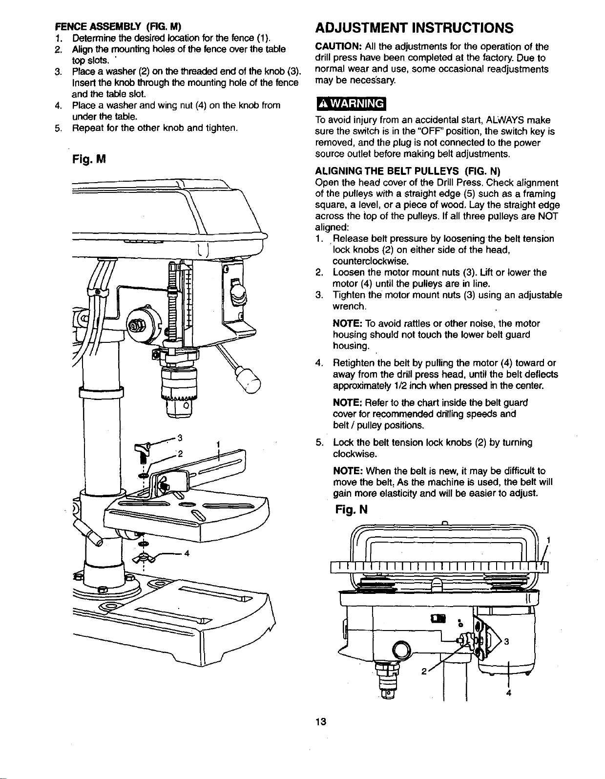
ALIGNING THE BELT PULLEYS (FIG. N)
Open the head cover of the Drill Press. Check alignment
of the pulleys with a straight edge (5) such as a framing
square, a level, or a piece of wood, Lay the straight edge
across the top of the pulleys. If all three pulleys are NOT
aligned:
1.. Release belt pressure by loosening the belt tension
lock knobs (2) on either side of the head,
counterclockwise.
2. Loosen the motor mount nuts (3). Lift or lower the
motor (4) until the pulleys are in line.
3. Tighten the motor mount nuts (3) using an adjustable
wrench.
4.
5.
NOTE: To avoid rattles or other noise, the motor
housing should not touch the lower belt guard
housing.
Retighten the belt by pulling the motor (4) toward or
away from the drill press head, until the belt deflects
approximately 1/2 inch when pressed in the center.
NOTE: Refer to the chart inside the belt guard
cover for recommended ddllingspeeds and
belt / pulley positions.
Lock the belt tension lock knobs (2) by turning
clockwise.
NOTE: When the belt is new, itmay be difficultto
move the belt, As the machine is used, the belt will
gain more elasticity and will be easier to adjust.
Fig. N
13
To prevent personal injury,always disconnectthe plug from
the power source when making any adjustments.
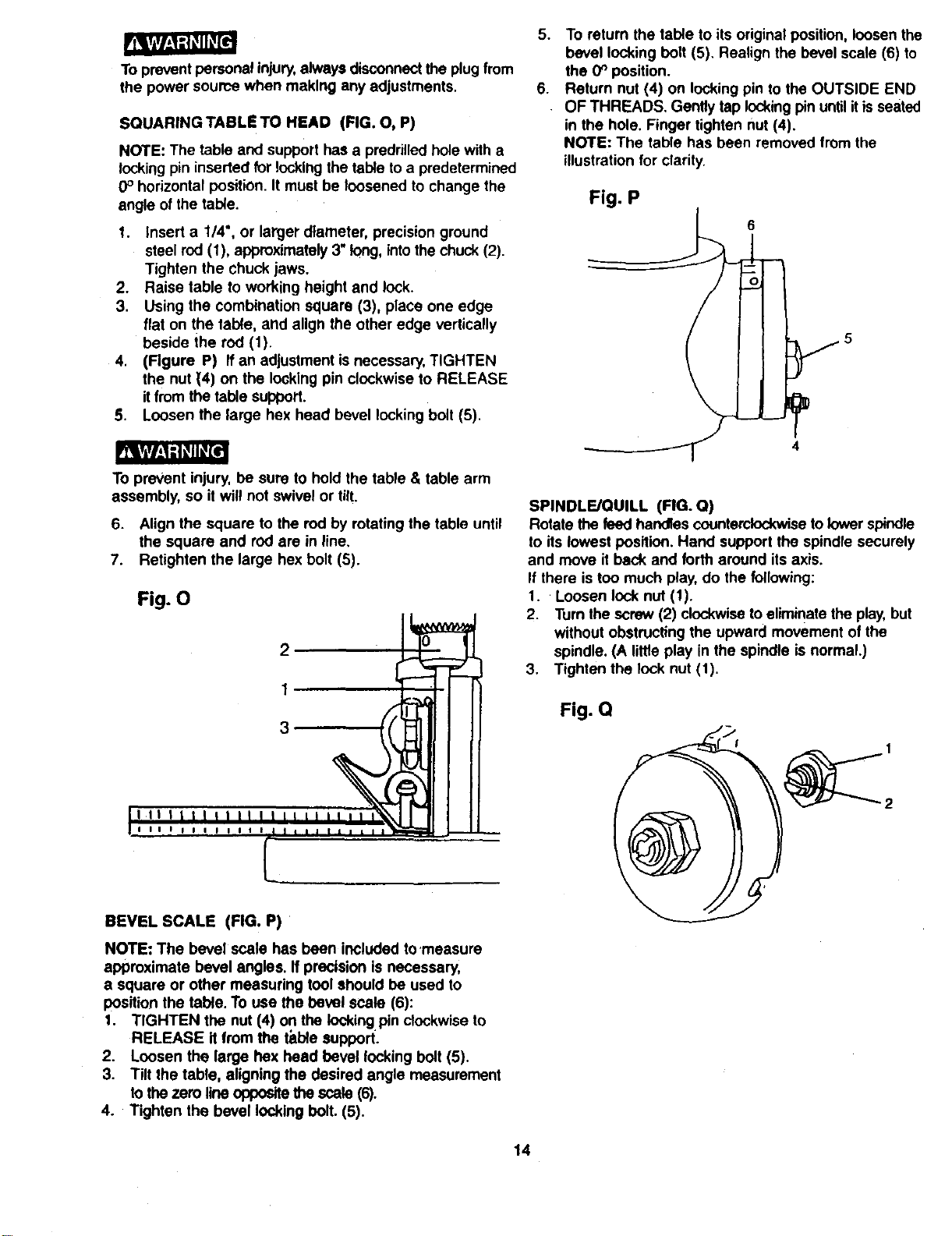
SQUARINGTABLETO HEAD (FIG. O, P)
NOTE: The table and support has a predrilledhole with a
locking pininserted for locking the table to a predetermined
0° horizontal position. It must be loosened to change the
angle of the table.
1. Insert a 1/4", or larger diameter, precision ground
steel rod (1), approximately 3"long, intothe chuck (2).
Tighten the chuck jaws.
2. Raise table to working height and lock.
3. Using the combination square (3), place one edge
flat on the table, and align the other edge vertically
beside the rod (1).
4. (Figure P) If an adjustment is necessary,TIGHTEN
the nut (4) on the looking pin clockwise to RELEASE
it from the table support.
5. Loosen the large hex head bevel locking bolt (5).
To prevent injury, be sure to hold the table & table arm
assembly, so it will not swivel or tilt.
6. Align the square to the rod by rotating the table until
the square and rod are in line.
7. Retighten the large hex bolt (5).
Fig. O
2
1
3
5. To return the table to its original position, loosen the
bevel locking bolt (5). Realign the bevel scale (6) to
the 0_ position.
6. Return nut (4) on lockingpin to the OUTSIDE END
OF THREADS. Gently tap lockingpinuntil itis seated
in the hole. Finger tighten nut (4).
NOTE: The table has been removed from the
illustration for clarity.
Fig. P
6
SPINDLE/QUILL (RG. Q)
Rotate the feed handles counterclockwiseto lowerspindle
to itslowest position. Hand support the spindle securely
and move it back and forth around itsaxis.
If there is too much play,do the following:
1. Loosen lock nut (1).
2. Turn the screw (2) clockwiseto eliminate the play,but
without obstructing the upward movement of the
spindle. (A little play in the spindle is normal.)
3. Tighten the lock nut (1).
Fig. Q
BEVEL SCALE (FIG. P)
NOTE: The bevel scale has been included to'measure
approximate bevel angles. If precision is necessary,
a square or other measuring tool should be used to
position the table. To use the bevel scale (6):
1. TIGHTEN the nut (4) on the locking pinclockwise to
RELEASE it from the table support.
2. Loosen the large flex head bevel locking bolt (5).
3. Tilt the table, aligning the desired angle measurement
to the zero line oppositethe scale (6).
4. Tighten the bevel locking bolt. (5).
14
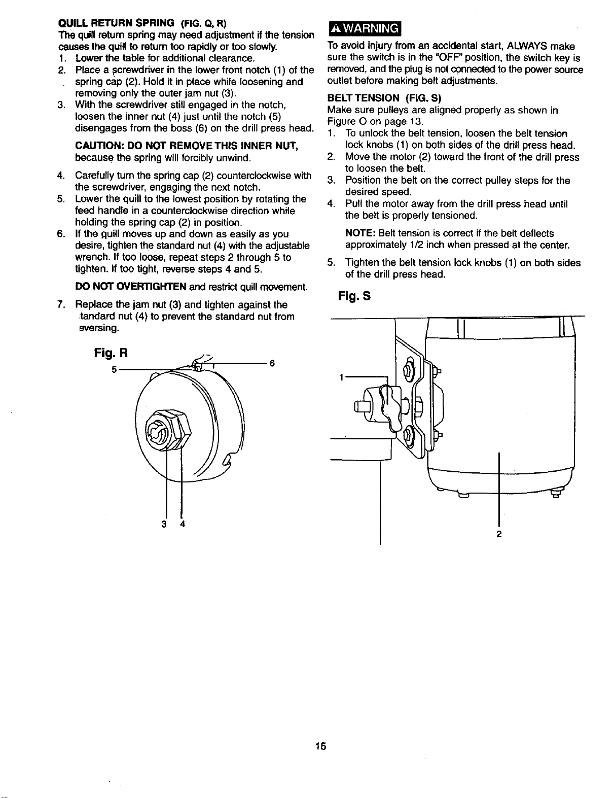
QUILL RETURN SPRING (FIG. Q, R)
The quillreturn spring may need adjustment if the tension
causes the quill to return too rapidlyor too slowly,
1. Lower the table for additional clearance.
2. Place a pcrewdr_ver in the lower front notch (1) of the
spring cap (2). Hold it in place while loosening and
removing only the outer jam nut (3).
3. With the screwdriver stillengaged in the notch,
loosen the inner nut (4) just until the notch (5)
disengages from the boss (6) on the drill press head.
_vlvl-1_l L'ql_(
CAUTION: DO NOT REMOVETHIS INNER NUT,
because the spring will forciblyunwind.
4. Carefully turn the spring cap (2) counterclockwise with
the screwdriver, engaging the next notch.
5. Lower the quillto the lowest position by rotating the
feed handle in a counterclockwise direction while
holding the spring cap (2) in position.
6. If the quill moves up and down as easily as you
desire, tighten the standard nut (4) with the adjustable
wrench. If too loose, repeat steps 2 through 5 to
tighten. If too tight, reverse steps 4 and 5.
DO NOT OVERTIGHTEN and restdct quillmovement.
7. Replace the jam nut (3) and tighten against the
,tandard nut (4) to prevent the standard nut from
eversmg.
Fig. R
3 4
To avoid injury from an accidental start, ALWAYS make
sure the switch is in the =OFF" position, the switch key is
removed, and the plug isnot connectedto the power source
outlet before making belt adjustments.
BELTTENSION (FIG. S)
Make sure pulleys are aligned properly as shown in
Figure O on page 13.
1. To unlock the belt tension, loosen the belt tension
lock knobs (1) on both sides of the drill press head.
2. Move the motor (2) toward the front of the drillpress
to loosen the belt.
3. Position the belt on the correct pulley steps for the
desired speed.
4. Pull the motor away from the drill press head until
the belt is properly tensioned.
NOTE: Belt tension is correct if the belt deflects
approximately 1/2 inch when pressed at the center.
5. Tighten the belt tension lock knobs (1) on both sides
of the drill press head.
Fig. S
1
J
15
BASIC DRILL PRESS OPERATIONS
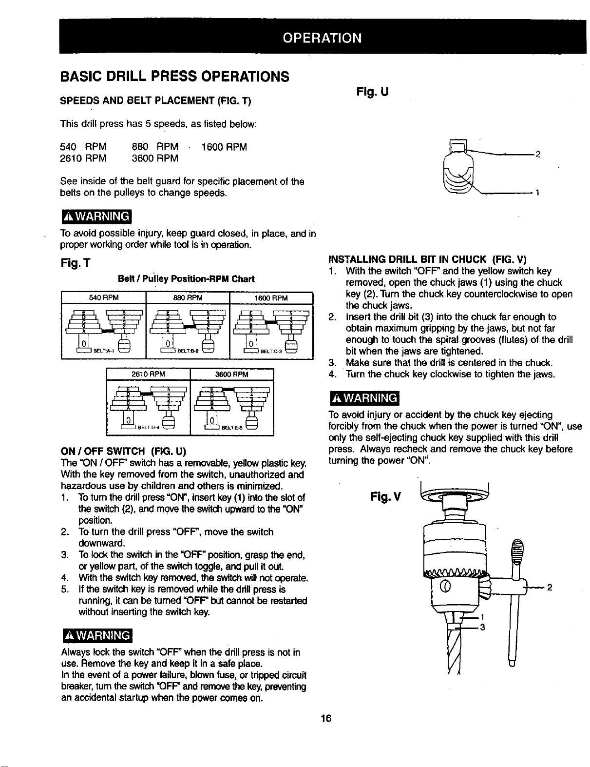
SPEEDS AND BELT PLACEMENT (FIG. T)
This drill press has 5 speeds, as listed below:
540 RPM 880 RPM 1600RPM
2610 RPM 3600 RPM
See inside of the belt guard for specific placement of the
belts on the pulleys to change speeds.
Fig. U
To avoid possible injury, keep guard closed, in place, and in
proper working order while tool is in operation.
Fig. T
Belt I Puiley Position-RPM Chart
540 RPM 880 RPM 1600 RPM
2610 RPM 3600 RPM
ON / OFF SWITCH (FIG. U)
The "ON / OFF' switchhas a removable, yellowplastickey.
With the key removed from the switch, unauthorized and
hazardous use by children and others is minimized.
1. To turnthe drillpress "ON", insertkey (1) intothe slotof
the switch (2), and move the switch upwardto the "ON"
position.
2. To turn the drill press "OFF", move the switch
downward.
3. To lock the switch in the "OFF position, graspthe end,
or yellow part, ofthe switchtoggle, and pullit out.
4. With the switchkey removed,the switchwillnotoperate.
5. Ifthe switch key is removedwhile the ddllpress is
running,it can be turned"OFF" but cannotbe restarted
without insertingthe switch key.
Always lock the switch"OFF" when the drill press is not in
use. Remove the key and keep it in a safe place.
In the eventof a powerfailure, blownfuse, or trippedcircuit
breaker,turn the switch"OFF' and removethekey,preventing
an accidental startup when the powercomes on.
INSTALLING DRILL BIT IN CHUCK (FIG. V)
1. With the switch "OFF" and the yellow switch key
removed, open the chuck jaws (1) using the chuck
key (2). Turn the chuck key counterclockwise to open
the chuck jaws.
2. Insert the drill bit (3) into the chuck far enough to
obtain maximum gripping by the jaws, but not far
enough to touch the spiral grooves (flutes) of the drill
bit when the jaws are tightened.
3. Make sure that the drillis centered in the chuck.
4. Turn the chuck key clockwise to tighten the jaws.
To avoid injury or accident by the chuck key ejecting
forcibly from the chuck when the power is turned "ON", use
only the self-ejecting chuck key supplied with this drill
press. Always recheck and remove the chuck key before
turning the power "ON".
Fig. V
16
To prevent the workpiece or backup material from being
torn from your hands whiledrilling,you MUST positionthe
workpiece against the LEFT side of the column.If the
workpiece or the backupmaterial is not longenough to
reach the column, clamp them to the table,or use the fence
providedwith the drillpressto brace theworkpiece.Failure
to secure the workpiece could resultinpersonal injury.
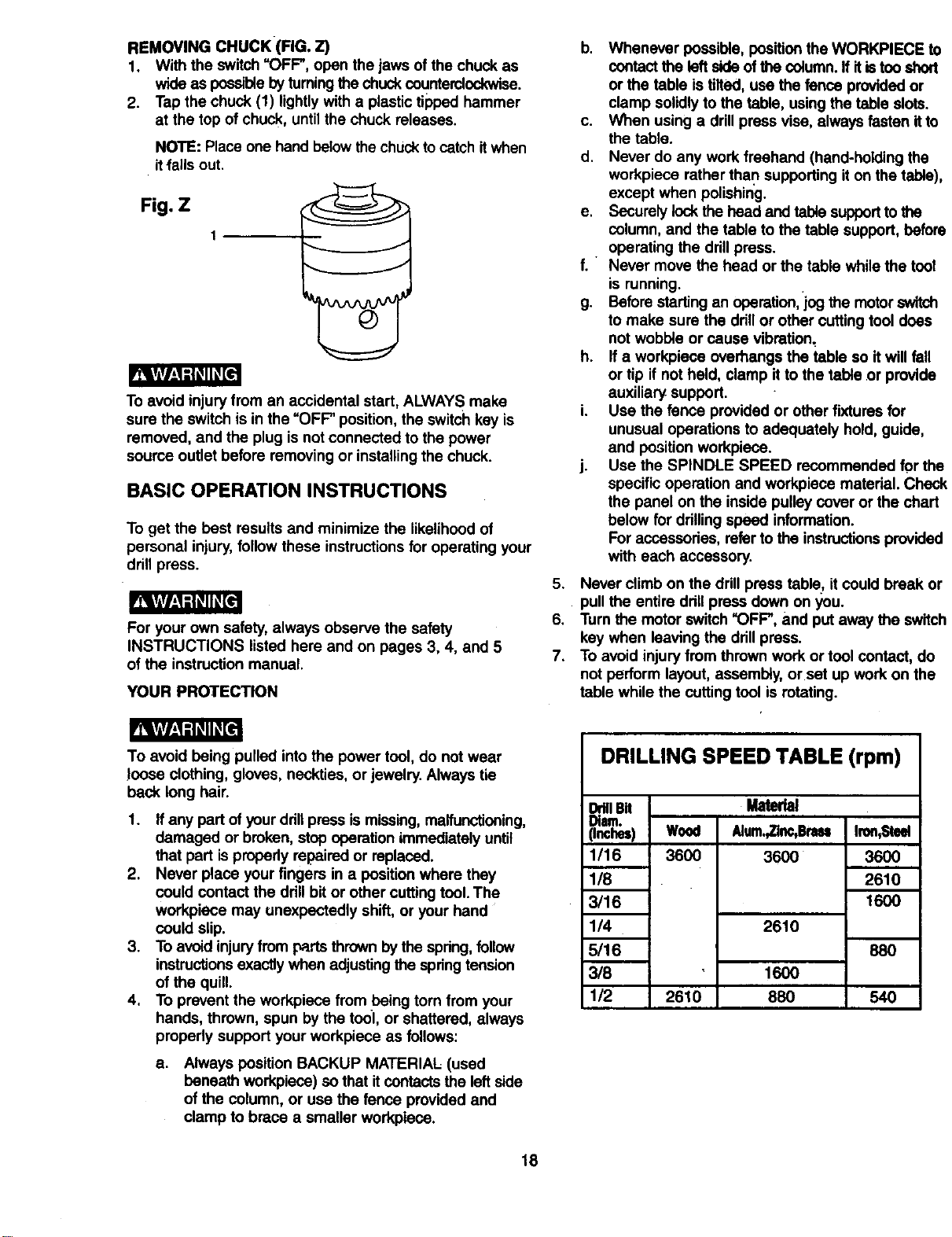
USINGTHE FENCE (FIG. W)
The fence provides a way of accurately and quickly
setting up the workpiece for more precision or repetitive
drillingoperations.
1. Using the centerpunch or sharp nail, make an
indentation in the workpiece where you want to drill.
2. Lower the drillbit to align with the indentation on the
workpiece. See =HOLDING A DRILLING LOCATION"
page 19.
3. Loosen the knobs(1) and slide the fence backstop (2)
firmly against the longside ofthe workpiece. Tighten
the knobs when in position.
4. Loosenthe wing nut(3) and slidetheend stop (4) along
the fence until it is firmlyagainst the leftside of the
workpiece. Tighten the wing nut.
5. Check the accuracy by drillinga scrap workpiece.
Adjust if needed.
6. Hold with your hand or clamp the top surface ofthe
workpiece firmly to prevent it from liftingoff the table
when the bit is raised.
Fig, W
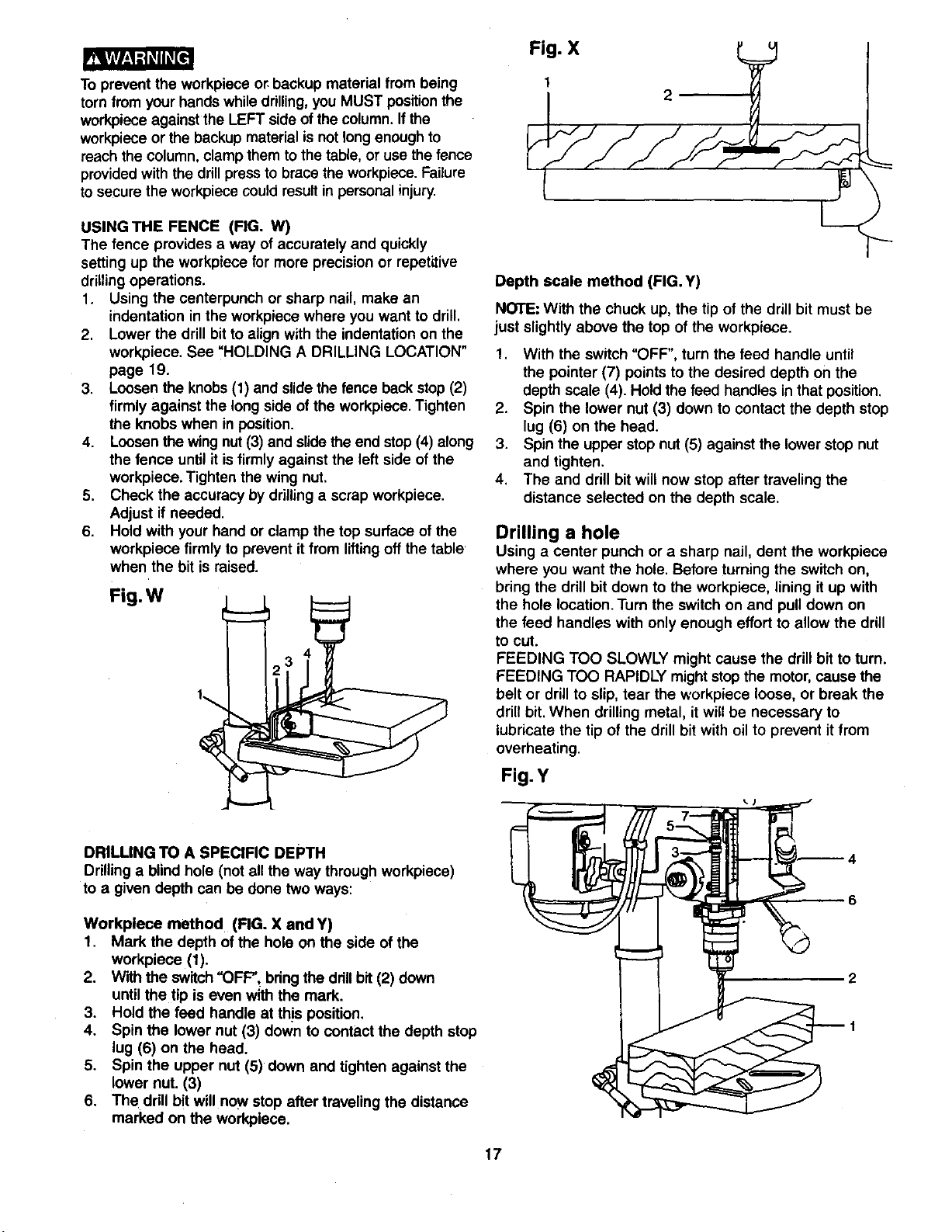
DRILLING TO A SPECIFIC DEPTH
Drilling a blind hole (not all the way through workpiece)
to a given depth can be done two ways:
Workplece method (FIG. X and Y)
1. Mark the depth of the hole on the side of the
workpiece (1).
2. Withthe switch "OFF", bdng the drillbit (2) down
until the tip is even with the mark.
3. Hold the feed handle at th!s position.
4. Spin the lower nut (3) down to contact the depth stop
lug (6) on the head.
5. Spin the upper nut (5) down and tighten against the
lower nut. (3)
6. The drill bit will now stop after traveling the distance
marked on the workpiece.
Fig. X
1
2
Depth scale method (FIG. Y)
NOTE: With the chuck up, the tip of the drill bit must be
just slightly above the top of the workpiece.
!. With the switch "OFF', turn the feed handle until
the pointer (7) points to the desired depth on the
depth scale (4). Hold the feed handles in that position.
2. Spin the lower nut (3) down to contact the depth stop
lug (6) on the head.
3. Spin the upper stop nut (5) against the lower stop nut
and tighten.
4. The and drill bit will now stop after traveling the
distance selected on the depth scale.
Drilling a hole
Using a center punch or a sharp nail, dent the workpiece
where you want the hole. Before turning the switch on,
bring the drillbit down to the workpiece, lining it up with
the hole location. Turn the switch on and pull down on
the feed handles with only enough effort to allow the drill
to cut.
FEEDING TOO SLOWLY might cause the drill bit to turn.
FEEDING TOO RAPIDLY mightstop the motor,cause the
belt or drillto slip, tear the workpiece loose, or break the
drillbit.When drilling metal, it will be necessary to
lubricate the tip of the drill bit with oil to prevent it from
overheating.
Fig. Y
17
REMOVING CHUCK (FIG. Z)
1. With the switch=OFF", open the jaws ofthe chuck as
wide as possiblebyturningthe chuckcounterclockwise.
2. Tap the chuck (1) lightlywith a plastictipped hammer
at the top of chuck, until the chuck releases.
NOTE: Place one hand belowthe chuckto catchit when
it'fallsout.
Fig. Z
To avoid injury from an accidental start, ALWAYS make
sure the switch is in the "OFP position, the switch key is
removed, and the plug is not connected to the power
source outlet before removing or installingthe chuck.
BASIC OPERATION INSTRUCTIONS
To get the best results and minimize the likelihood of
personal injury,follow these instructionsfor operating your
drill press.
For your own safety, always observe the safety
INSTRUCTIONS listed here and on pages 3, 4, and 5
of the instruction manual.
YOUR PROTECTION
b. Whenever possible, positionthe WORKPIECE to
contactthe leftside of the column.If it istoo short
or the table is tilted, use the fence provided or
clamp solidlyto the table, using the table slots.
c. When using a drillpress vise, always fasten itto
the table.
d. Never do any work freehand (hand-holding the
workpiece rather than supporting iton the table),
except when polishing.
e. Securelylock the head and table supportto the
column,and the table to the table support, before
operating the drill press.
f. " Never move the head or the table while the tool
is running.
g. Beforestarting an operation,log the motorswitch
to make sure the drillor other cutting tool does
not wobble or cause vibration,
h. If a workpiece overhangs the table so itwill fall
or tip if not held, clamp itto the table .orprovide
auxiliary support.
i. Use the fence provided or other fixtures for
unusual operations to adequately hold, guide,
and position workpiece.
j. Use the SPINDLE SPEED recommended for the
specific operation and workplace material. Check
the panel on the inside pulley cover or the chart
below for drilling speed information.
Foraccessories, referto the instructionsprovided
with each accessory.
5. Never climb on the drill press tablet it could break or
pull the entire drillpress down on you.
6. Turn the motor switch "OFF", and put away the switch
key when leavingthe drill press.
7. To avoid injury from thrown work or tool contact, do
not perform layout, assembly, or set up work on the
table while the cutting tool is rotating.
_I:_ -'_ II_[e_
To avoid being pulled into the power tool, do not wear
loose clothing, gloves, neckties, or jewelry. Always tie
beck long hair.
1. ffany part of your drillpress is missing,malfunctioning,
damaged or broken, stop operation immediately until
that part ispropedy repaired or replaced.
2. Never place your fingers in a position where they
could contact the drillbit or other cutting tool. The
workpiece may unexpectedly shift, or your hand
could slip.
3. To avoid injuryfrom parts thrown by the spring,foUow
instructionsexactly when adjustingthe springtension
of the quill.
4. To prevent the workpiece from being torn from your
hands, thrown, spun by the to01,or shattered, always
properly support your workpiece as follows:
a.
Always position BACKUP MATERIAL (used
beneath workpiece) so that it contactsthe leftside
of the column, or use the fence provided and
clamp to brace a smaller workplece.
DRILLING SPEED TABLE (rpm)
Material
Wood Alum.,Zlnc,Bnm
3600 3600
DrillBit
Diam.
(Inches)
1/16
1/8
3/16
1/4
5/16
3/8
1/2
2610
2610
1600
88O
Iron,Steel
36OO
2610
1600
88O
540
18
POSITIONING THE TABLE AND WORKPIECE
(FIGURE AA and BB)
1. Lock the table (1) to the column (2) at a position so
the tip of the dnll bit (3) is Justabove the top of the
workpiece (4).
2. ALWAYS place a BACK-UP MATERIAL (scrap wood)
on the table beneath the workpiece. This will prevent
splintering or heavy burring on the underside of the
workpiece. To keep the back-up material from spinning
out of control, it MUST contact the LEFT side of the
column.
To prevent the workplace or backup material from being
torn from your hands while drilling, you MUST position it
against the left side of the column. Ifthe workpiece or
the backup material iS not long enough to reach the
column use the fence provided with the drill press to
brace the workpiece, or clamp it to the table. Failure to
do this could result in personal injury.
.,Fig. AA
3. For small pieces that cannot be clamped to the table,
use a drill press vise (optional accessory).
_Y/zI_iI_
The drill pf'ess vise MUST be clamped or bolted tq the
table to avoid injuryfrom a spinningworkplace, or
damaged vise or bit parts.
Remove the drill press fence when it interferes with other
drill press accessories.
Fig. BB
HOLDING A DRILLING LOCATION
1. Using a centerpunch or sharp nail, make an
indentation in the workplace where you want the hole.
2. Using the feed handles, bring the drill down to align
with the indentation before turning the drill "ON".
TILTING THE TABLE (FIGURE CC)
NOTE: The table and support (t) has a predrilled hole
with a locking pin inserted for locking the table into a
predetermined 0° horizontal position.
1. To use the table in a bevel (tilted) position, TIGHTEN
the nut (2) on the lockingpin clockwise to RELEASE
itfrom the table support.
2. Loosen the large hex head bevel lockingbolt (3).
To prevent injury, be sure to hold the table & table arm
assembly, so it will not swivel or tilt.
Fig. CC
/- ,m,,==_,_==_m
,mm_mmma_m='
I
k3 1
2
3. Tilt the table, aligningthe desired angle measurement
tothe zero line oppositethe scale (4).Tighten the bevel
locking bolt.
4. To return the table to its original position, loosen the
bevel locking bolt,(3). Realign the bevel scale (4) to
the 0° position.
5. Loosen the nut (2) on the lockingpin to the OUTSIDE
END OF THREADS. Gently tap the lockingpinuntil it
is seated in the hole. Finger tightenthe nut.
To avoid injury from spinningwork or tool breakage, always
clamp workpiece and backup material securely to the
table before operating the drill press with the table tilted,
FEEDING
1. Pull down the feed handles with only eno_ugheffort to
allow the drill bit to cut.
2. Feeding too slowly might cause the drill bit to burn.
Feeding too rapidly might stop the motor, cause the
belt or ddUto slip, or tear the workplece loose and
break the drillbit.
3. When drillingmetal, it may be necessary to lubricate
the drillbit tip with motor oil,to prevent burningthe tip.
19
MAINTAINING YOUR DRILL PRESS
For your own safety, turn the switch OFF and remove the
plug from the power source outlet before maintaining or
lubricating your drill press.
Frequently blow out using an air compressor or dust
vacuum, any dust that accumulates inside the motor.
A coat of automotive" paste wax applied to the table and
column will help to keep the surfaces clean.
To avoid shock or fire hazard, if the power cord is worn
or cut in any way, have it replaced immediately.
LUBRICATION
All of the drill press ball bearings are packed with grease
at the factory. They require no further lubrication.
Periodically lubricate the gear and rack, table elevation
mechanism ofthe spindleand the rack(teeth) ofthe quill.
2O
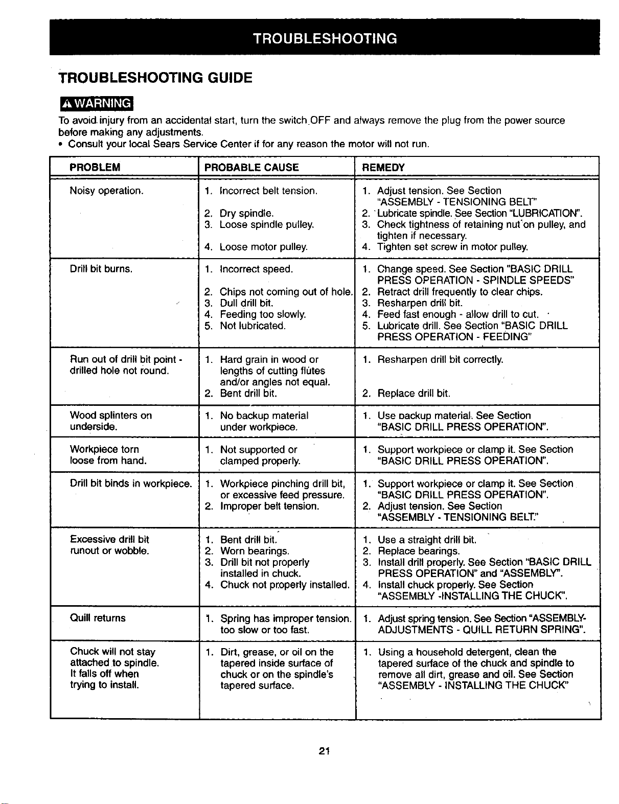
TROUBLESHOOTING GUIDE
To avoid,injury from an accidental start, turn the switch OFF and always remove the plug from the power source
before making any adjustments.
• Consult your local Sears Service Center if for any reason the motor will not run.
PROBLEM PROBABLE CAUSE REMEDY
Noisy operation. 1. Adjust tension. See Section
"ASSEMBLY - TENSIONING BELT"
2. "Lubricate spindle. See Section "LUBRICATION".
3. Check tightness of retaining nut'on pulley, and
tighten if necessary.
4. Tighten set screw in motor pulley.
Drill bit burns. 1.
1.
2.
3.
4.
1.
2.
3.
4.
5.
Incorrect belt tension.
Dry spindle.
Loose spindle pulley.
Loose motor pulley.
Incorrect speed.
Chips not coming out of hole.
Dull drill bit.
Feeding too slowly.
Not lubricated.
Change speed. See Section "BASIC DRILL
PRESS OPERATION - SPINDLE SPEEDS"
2. Retract drill frequently to clear chips.
3. Resharpen drift bit.
4. Feed fast enough - allow drill to cut. •
5. Lubricate drill. See Section "BASIC DRILL
PRESS OPERATION - FEEDING"
Run out of drill bit point - 1. Hard grain in wood or 1. Resharpen drill bit correctly.
drilled hole not round, lengths of cutting flutes
and/or angles not equal.
2. Bent drill bit. 2. Replace drill bit.
Wood splinters on 1. No backup material 1. Use cackup material. See Section
underside, under workpiece. "BASIC DRILL PRESS OPERATION".
Workpiece torn 1. Not supported or 1. Support workpiece or clamp it. See Section
loose from hand. clamped properly. "BASIC DRILL PRESS OPERATION".
Drill bit binds in workpiece. 1. Workpiece pinching drill bit, 1. Support workpiece or clamp it. See Section
or excessive feed pressure. "BASIC DRILL PRESS OPERATION".
2. Improper belt tension. 2. Adjust tension. See Section
"ASSEMBLY - TENSIONING BELT."
Excessive drill bit 1. Bent drill bit. 1. Use a straight drill bit.
runout or wobble. 2. Worn bearings. 2. Replace bearings.
3. Drill bit not properly 3. Install drill properly. See Section "BASIC DRILL
installed in chuck. PRESS OPERATION" and "ASSEMBLY".
4. Chuck not properly installed. 4. Install chuck properly. See Section
"ASSEMBLY -INSTALLING THE CHUCK".
Quill returns 1. Spring has improper tension. 1. Adjust spring tension. See Section"ASSEMBLY-
too slow or too fast. ADJUSTMENTS - QUILL RETURN SPRING".
Chuck will not stay 1. Dirt, grease, or oil on the 1. Using a household detergent, clean the
attached to spindle, tapered inside surface of tapered surface of the chuck and spindle to
It falls off when chuck or on the spindle's remove all dirt, grease and oil. See Section
trying to install, tapered surface. "ASSEMBLY - INSTALLING THE CHUCK"
21
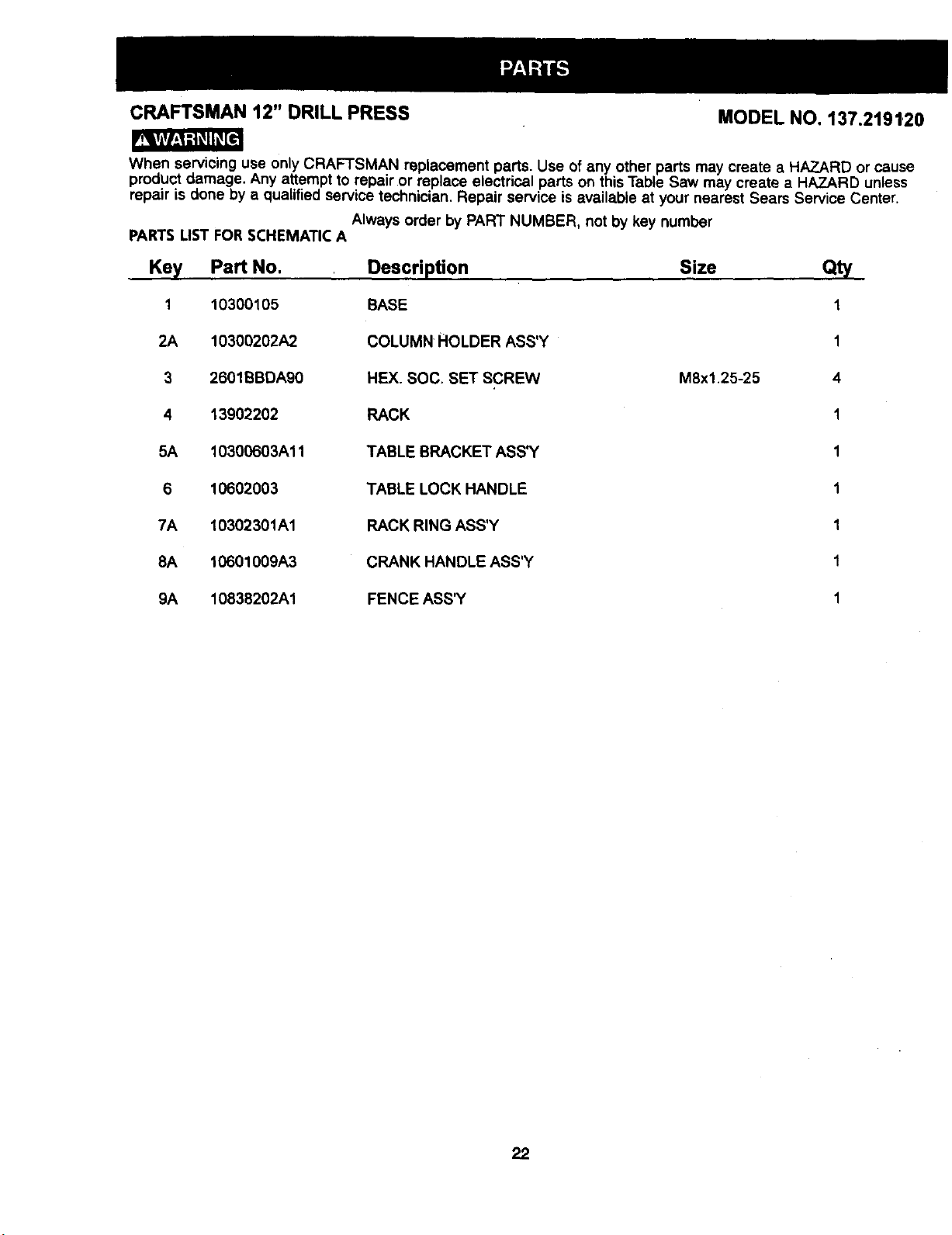
CRAFTSMAN 12" DRILL PRESS MODEL NO, 137.2191,20
When servicing use only CRAFTSMAN replacement parts. Use of any other parts may create a HAZARD or cause
product damage. Any attempt to repair or replace electrical parts on this Table Saw may create a HAZARD unless
repair is done by a qualified service technician. Repair service is available at your nearest Sears Service Center.
Always order by PART NUMBER, not by key number
PARTS UST FOR SCHEMATIC A
Key Part No.
1 10300105
2A 10300202A2.
3 2601BBDAg0
4 13902202
5A 10300603A11
6 10602003
7A 10302301A1
8A 10601009A3
9A 10838202A1
Description
BASE
COLUMN HOLDER ASS'Y
HEX. SOC. SET SCREW
RACK
TABLE BRACKET ASS'Y
TABLE LOCK HANDLE
RACK RING ASS'Y
CRANK HANDLE ASS'Y
FENCE ASS_
Size Qty
M8x1.25-25
1
1
4
1
1
1
1
1
1
22
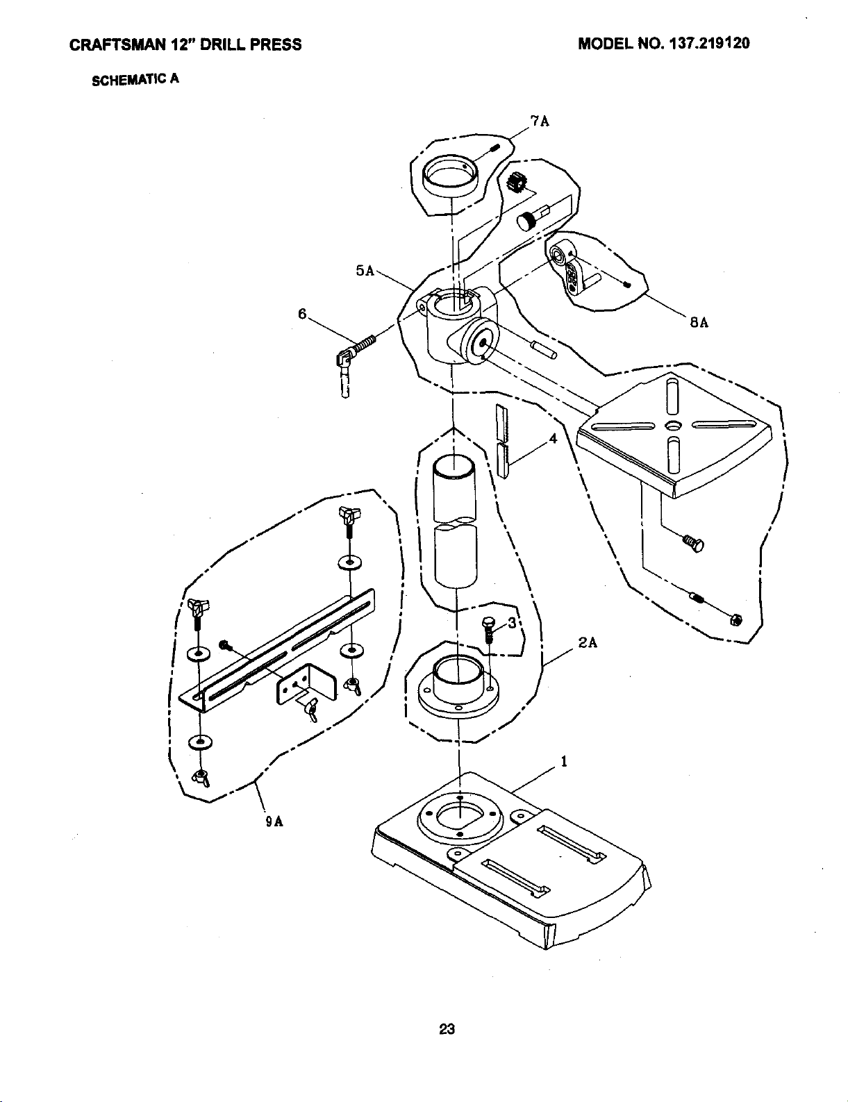
CRAFTSMAN12" DRILLPRESS
SCHEMATICA
MODEL NO. 137.219120
?A
"gA
I
23
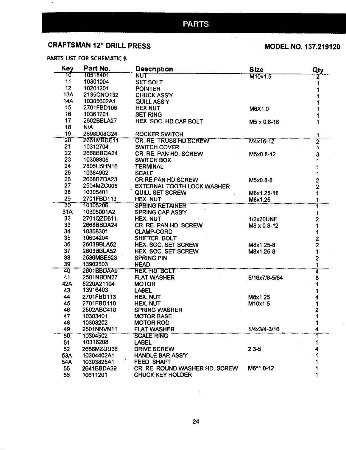
CRAFTSMAN 12" DRILL PRESS MODEL NO. 137.219120
PARTSLIST FOR SCHEMATIC B
Kf0y Part No. Description
10518401 NUT
11 10301004 SET BOLT
12 10201201 POINTER
13A 2135CNO132 CHUCK ASS'Y
14A 10305602A1 QUILL ASS'Y
15 2701FBD106 HEX NUT
16 10361701 SET RING
17 2602BBLA27 HEX. SOC. HD,CAP BOLT
18 N/A
19 2898D08G24 ROCKER SWITCH
S ize
M1Ox1.5
M6X1,0
M5 x 0.8-16
aty
2
1
1
1
1
1
1
1
..........."2"_...........26t_,lMr_oE]:f..............."(3RTR'ETTRO_;RI3";9"¢RItW ....................................I_Y:1"6"-"_2......................................":P...........
21 10312704 SWITCH COVER 1
22 2668BBDA24 CR. RE. PAN HD. SCREW M5x0.8-12 3
23 10308805 SWITCH BOX 1
24 2805U5HN16 TERMINAL 1
25 10384902 SCALE 1
26 2668BZDA23 CR.RE.PAN HD SCREW M5x0.8-8 2
27 2504MZC005 EXTERNAL TOOTH LOCK WASHER 2
28 10305401 QUILL SET SCREW M8x1.25-18 1
29 2701FBD113 HEX. NUT M8x1.25 1
..........._ ..........."_'_'0"_'_0i_........................"_PRIR_3RET;_II_ER................i......................................................................................................t..........
31A 10305001A2 SPRING CAP ASS'Y 1
32 2701QZD611_ HEX. NUT I/2x20UNF 2
33 2668BBDA24 CR. RE. PAN HD. SCREW M8 x 0.8-12 1
34 10808301 CLAMP-CORD 1
35 10604204 SHIFTER BOLT 2
36 2603BBLA52 HEX. SOC. SET SCREW M8x1.25-8 2
37 2603BBLA52 HEX. SOC. SET SCREW M8x1.25-8 1
38 2536MBE623 SPRING PIN 2
39 13902503 HEAD 1
...........;41_...........2_0"=I'I_B_;_...............FIE'XTR'D'_i31LT.............................................................................................................................."_.........
41 2501NBDN27 FLAT WASHER 5116x718-5164 8
42A 8220A21104 MOTOR 1
43 13916403 LABEL 1
44 2701FBD113 HEX. NUT M8xl.25 4
45 2701FBD110 HEX. NUT M10xl.5 1
46 2502ABC410 SPRING WASHER 2
47 10303401 MOTOR BASE 1
48 10303202 MOTOR ROD 1
49 2501NNVN11 FLAT WASHER 1/4x3/4-3/16 4
..........._ ..........."_'_'0"_1502........................"_i3";_[It"R'll_.................................................................................................................................._..........
51 10316208
52 2658MZDU36
53A 10304402A1
54A 10303825A1
55 2641BBDA39
56 10611201
LABEL
DRIVE SCREW 2.3-5
HANDLE BAR ASS'Y
FEED SHAFT
CR. RE. ROUND WASHER HD. SCREW M6"1.0-12
CHUCK KEY HOLDER
1
4
1
1
1
1
24
CRAFTSMAN12" DRILL PRESS
SCHEMATICB
MODEL NO. 137.219120
45
54A
35
11
it0
25
CRAFTSMAN 12" DRILL PRESS
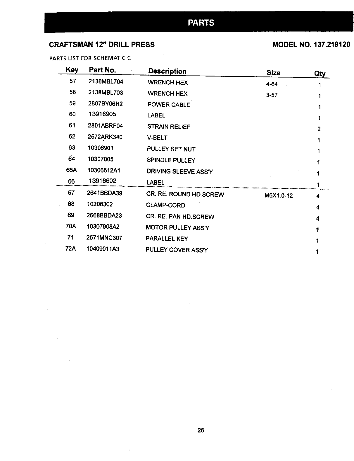
PARTSUST FOR SCHEMATIC C
Key Part No. Description
57 2138MBL704 WRENCH HEX
58 2138MBL703 WRENCH HEX
59 2807BY06H2 POWER CABLE
60 13916905 LABEL
61 2801ABRF04 STRAIN RELIEF
62 2572ARK340 V-BELT
63 10306901 PULLEY SET NUT
6_4 10307005 SPINDLE PULLEY
65A 10306512A1 DRIVING SLEEVE ASS_'
66 13916602 LABEL
Size
4-64
3-57
MODEL NO. 137.2t912C
Qty
1
1
1
1
2
1
1
1
1
1
67 2641BBDA39
68 10208302
69 2668BBDA23
70A 10307908A2
71 2571MNC307
72A 10409011A3
CR. RE, ROUND HD.SCREW
CLAMP-CORD
CR. RE, PAN HD,SCREW
MOTOR PULLEY ASS'Y
PARALLEL KEY
PULLEY COVER ASS'Y
M6X1.0-12 4
4
4
1
1
1
26
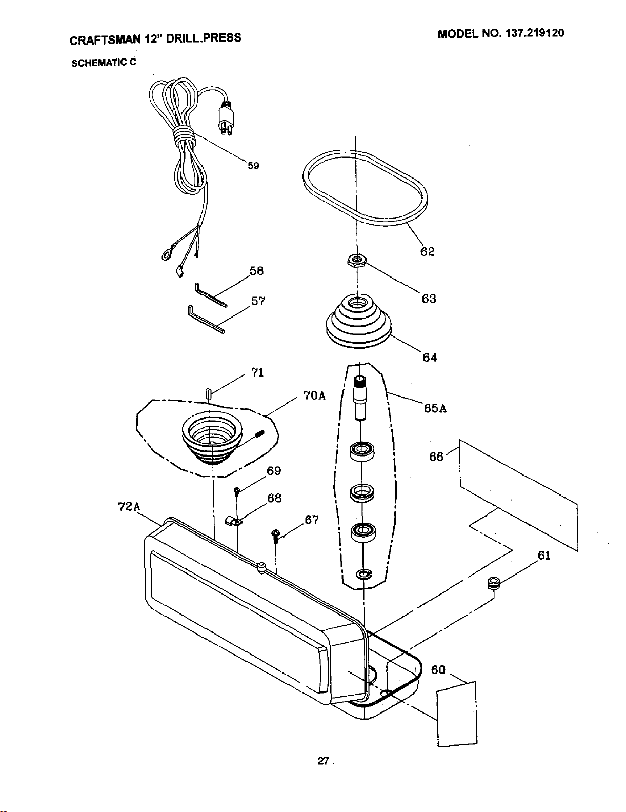
CRAFTSMAN12" DRILL.PRESS
SCHEMATICC
MODEI.NO.137.219120
59
71
70A
69
J
68
72A
64
65A
60
61
27

For repair of major brand appliances in your own home...
no matter who made it, no matter who sold it!
1,800-4-MY-HOME s"Anytime,day or night
(1-800-469-4663)
www.sears.com
To bring in products such as vacuums, lawn equipment and electronics
for rePair, cell for the location of your nearest Sears Parts & Repair Center
1.800-488-1222 _., dayorn_ht
www.sears.com
For the replacement parts, accessories and owner's manuals
that you need to do-it-yourself, call Sears PartsDirect =_!
1-800-366-PART 6a.m.-11p.m.CST,
(1-800-366-7278) 7 daysa week
www.sears.com/partsdirect
To purchase or inquire about a Sears Service Agreement:
1-800-827-6655
7 a.rn.'- 5 p.m. CST, Mon. - Sat.
.Pard pedir serviciode reparaclbna domidlio, Au Canada pour sewics en fran_ais:
y pardordenar piezas con entmga a domicilio: 1.877.LE.FOYER =.
1-888-SU-HOGAR TM
{1-888-784-6427)
SEARS
o,,,,,.,.=_,,.=, HomeCentrar ®.,.,=.,,,,,-.-,'-,,.-_ ,,=..,.P-=_..,=.
J ® MatcaRegistrada_ MamadeF_brk_ deSeam,Roebu_ and CO.
FULLONEyEARWARRANTY
If_ i_uCt failsduetOa defe<_inmateri_d_ v,_kmansh_owi_-_ o_e_u _ _ _ _ _. _
_ re_t_it_ ofch_ge.
ConUtctaSearsSer_e C_mUvfo_"m_.
If G_isl_ct i.Jusedfor€ommerdaiorrentalpurpo_s, thiswamu_ _ onlyf_' g0dlys fromlhe _ _
pufcJuse.
'n_ *tmtr¢/g_,,es you_ legaldg_s_end_oumaymo h=_ oG_"rklt_tswNchvsry _'om_ _ s_
_an=, Roeb_mk and Co., DepL 817 WA, Hoffrmm Eatates, IL eO179
11/200(
Manual de Operacibn
CRRFTSMRN°
2/3HP (Potencia M_xima)
5 Velocidades (540-3600 R.P.M.)
Mandril de 1/2 Pulg.
PRENSA TALADRADORA
DE 12 PULG.
Modelo No.
137,219120
CUIDADO:
/
Antes de usar esta Prensa
Taladradora leer este manual
y seguir todas las Reglas de
Seguridad e instrucciones
de Operaci6n
Sears, Roebuck and
USA
Part No.137219120001
.0
Instrucciones de Seguridad
Instalaci6n
Operaci6n
Mantenimiento
Lista de Partes
Tel6fono para
Ayuda al Cliente
1.800-843-1682
Co., Hoffman Estates, IL 60179
SECCION PAGINA
Garantia ............................................................................ 30
Especificaciones de la Herramienta ...................................................... 30
Instrucciones de Seguridad ........................................................... :31
Accesorios y Aditamentos ............................................................. :34
Contenido de la Caja ................................................................. :34
Familiarizarse con la Prensa Taladradora ................................................. :36
Glosario de Terminos ................................................................. 37
Ensamblaje y Regulacibn .............................................................. 38
Operaci6n ................................................................. )......... 43
Mantenimiento ..................................................................... .48
Guia para Diagn6stico de Problemas ................ "................................... 49
Partes : ............................................................................ 50
TAMANODEL MANDRIL .1/2"(13ram)
VELOC]DADES ........ 5 (540-3,600 RPM)
MOTOR ........ '...... 120V._0 HZ,6 AMFS.
CABALLAJE ........... 2/3 HP(Desarroflo Maxi.)
LUZ INCORPORADA ...... 60 Wars(Maximo)
(Notnduye el foco)
TAMA_IODELA MESA
INCL]NACION
DE LA MESA ............
DESPLAZAMIENTO
DEL EJE ...............
CUELLO ...............
10-5/16" X 8-2!/32"
(26.2 cmx 22 cm)
450A LA OERECHAC IZQUJEROA
•2-3/8" (6 cm)
.6" (15.2cm)
Usar protecci6nadecuada en el circuitoparaevitar rles_os
e!e_ncos, de incenaio o _ah,os a la herramiema.
La PrensaT_Jaaraaoraesta cabteadaen la fa._ncapara cperara
120V. Conectarla_ un circuito de 120V.15Amps.y usarun
merrup[orce c:rcuito o fusibie de ,'etardode 15Amos.S;el
cora6nelec:ricoestuvlese gas{ado,cortadoo dar_aao,=n
cualquierform& reempiazartode Inmediatopara witar
eleotrocuci0no Incendio.
TAMAI_IODE LA BASE .... 14-3/8" X 8-1/4" (36.6cm X 21cm)
ALTURA ............. 37-3/32"/94.2cm)
Alogunos polvos creados por el lijado mec_mico, el aserrado, el esmedtado, el taladrado y otras
actividades de construccibn contienen sustancias quimicas conocidas [pot le Estado de California]
como agentes cancerigenos, defectos ¢ongenitos y otros daSos reproductores. Algunos
ejemplos de estas sustancias quimicas son:
• El plomo de las pinturas a base de plomo,
• El silice cristalino de los ladriltos y ¢emento y otros productos de mamposteria, y
• El arsenico y el ¢romo de la madera tratada quimicamente.
.El riesgo resultante de la exposition varia segQn la frecuencia con que se realiza este tipo de
trabajo. Para reducir la exposition a esta sustancias quimicas: trabaje en un lugar bien ventiiado y
realice el trabajo utilizando el equipamiento apropiado, tal como las re&scares para el oplvo
especialmente diser_ados para eliminar las pa.,'ticulas minQscutas.
30
INSTRUCCIONES GENERALES DE
SEGURIDAD
ANTES DE USARLAPRENSATALADRADORA
14. RETIRAR LAS HERRAMIENTAS DE
REGULACI6N. Formarseel habitodeverificarqualas
herramientasy lasIlavesde regulaci6nhayansidoretirades
del taladroantesde activado.
La seguridades una combinaci6nde sentido comdn,mantenerse
alertay sabercomo usar la PrensaTaladradora.
Para evitarerroresque puedancausarlesiones serias,no
conectarel taladro hasta haber leido y entandidoIosiguiente:
1.
.
3,
4.
5.
6.
7.
8.
LEER y familiarizarsecontodoeste manualde
instrucciones.ENTENDERlasaplisaciones, limitacionesy
riesgos posib_es,
MANTENER LOS PROTECTORESEN POSICI(_Ny en
buanascondicionesde operacibn.
NO OPERAR ENAMBIENTES PEMGROSOS.Nousarla
herramientaen lugaresh0medos,mojadoso expuestosa la
Iluvia.Mantenerelarea de trabajobien Uuminada.
NO USARherramiantaseldctficasenla presenciade
Iiquidosogases inflamables.
MANTENER EL AREA DETRABAJO UMPIA. Lasdreasy
mesasdetrabajocongestionadasinvitana quaocurran
accidantes.
MANTENERA LOS NINOSALEJADOS.To<loslos
visitantesdeben mantenersea unadistanciaseguradel
area de trabajo.
NO FORZARLA HERRAMIENTA,La herramientahard un
mejortrabajoy mas segurousandolas61oenla brma para
la que fue disefiada.
USARLA HERRAMIENTAADECUADA,Noforzarla
herramientaalhacer un trabajo paraelcual no ha sido
dise_ada.
9. USAR ROPAADECUADA.NO usarropasuelta,guantes,
corbatas,anillos,brazaletesni joyasque pusdanquedar
atrapadosan laspiezasmoviblesdela herramienta.Se
recomiendausarsalzado antiresbalante.Usarprendasde
sadeza paracubrir o contener el cabeUolargo.
!0. USAR UNAMASCARA PARALA CARAO PARAPOLVO.
Los trabajoscon taladro producanpolvo.
11. DESCONECTARLAS HERRAMIENTASantes decambiade
accesori0stalescomo:hojas,brocas,cortadoresysimilares.
12. REDUCIREL RIESGODEARRANQUESACCIDENTALES.
Cerciorarsequeel interruptordeenergfaesteen laposici6n
"OFF"(Apagado)antes de enchu_rla herramientaa la
corrienteeldctrica..
13. USARACCESORIOSRECOMENDADOS.Consultarcon
e! manualdel operador.paradeterminarcualessonlos
acossodosrecomendados.Elusode accesodos
inapropiadospuedeserpeligrosoyganerarriesgode
lesionespersonales.
15.
"16.
17.
18.
NUNCADEJARDESATENDIDAUNAHERRAMIENTA
ELI_CTRICACUANDOESTE FUNCIONANDO.
DESCONECTARLA FUENTEDE ENERGIA.Noalejarse
del lugar hastaque la herramientasehayadetenidopor
completo.
NUNCAPARARSESOBRE LA HERRAMIENTA.Pueden
ocurnrlesionessedassila herramientase volteao sise
entraencontactoconel taladro.
NO ESTIRARSEMAS ALI,.ADEL ALCANCEDE UNO.
Mantenerlosdospiesbienapoyadosyelequilibroen
todomomento.
DARMANTENIMIENTOCUIDADOSOA LAS
HERRAMIENTAS.Paraunaoperaci6nmejor,mas seguray
rapida,mantenertasherramientasafiladesy limpias.Seguir
lasinstrucoionespara lalubdcaci6ny carnbiodeaccesorios.
19. INSPECClONARPARADETECTARPIEZASDANADAS,
Antesdeusarlaharramienta,siempreinspeccionarla
_idadosamante parecercioraressilosprotectoresuotras
piezasestdndeSadasy determinarsiva a operar
adecuadamenteen el usoquese levaa dar.Inspeccionar
sihaypiezasmoviblesdesatineadaso atrasadas;partes
rotas omalmontadas,y cualquierotracondiciSnquepueaa
afectarlaoperaci6nde laherrarnienta.Siunprotectoro
cuaJquierotrapiezaestuvtesedefiada deberepararse
adecuadamenteo reemplazarse.
20. ASEGURARSEQUE LOSNItrOS NOTENGAN ACCESO
ALTALLERDETRABAJO.Usarcandados,interruptores
maestrosy quitarlasIlavesdeactivaci6n.
21.
22.
NO operarla herramientabajo la influenciade drogas,
alcoholo medicamentosque pudiesenafectarla habilidad
para operarla herramientaadecuadamente.
Et polvogeneradeporciertosmaterialespuede sernoctvo
parala salud.SiempreoperarlaPrensaTaladradoraenun
areabien ventiladaparaeliminarelpolvo.Cuandofuese
posib_e,usar sistemasrecolectoresde polvo.
23. SIEMPREUSAR
PROTECCI(_NPARALOS OJOS.
CualquierPrensaTaladradora
puedearrojarcuerposextrafiosa
losojosquapuedancausar
dafiospermanentesa lavista.
SIEMPREusarGafasde
Segurided(noanteojos) que cumplancon la norma7_87.1
de ANSI. Losanteojosde usodiado S61otienenlentes
resistantesa los impactos,estos NOSONgalas de
seguridad,l.as Galasde Seguridad puedenadquirirseen
Sears. NORA:Los anteojos o galasqua no cumplenconla
norma Z87.1de ANSI pueden causardafios serios al
romperse.
CONSERVAR ESTAS INSTRUCClONES
31
REGLASDESEGURIDADESPEC{FICAS
PARALA PRENSATALADRADORA
14.
15.
Porsu propiaseguddad,nottatarde usarla PrensaTaladradorani
enchufarlahastaque est_ completamente-ensambladae instalada 16.
de acuerdocon lasistrucciones,y hastahaberleido yentendido
este manualde instrucclones:
1.
2.
3.
4.
5.
LA PRENSA TALADRADORA DEBE ESTAR - 17.
EMPERNADA en forma segura al banco de trabajo.
Adicionalmente,si hubiese la tendenciaa que el
banco de trabajoTaladradorase muevadurante
ciertas operaciones,empernar ta prensaal piso. 18.
ESTAPRENSATALADRADORAs61oes para usarse en
condicionessecasyen interiores.
USARPROTECClONOCULAR,USARm&scaraprotectora 19.
parala carao parapolvosjunto congafasdeseguridadsi
laoperaci6ngenerapolvo.USARprotectoresdeofdo,
especialmenteduranteperiodoslargosde operaci6n. 20.
NOusar guantes,corbatani ropasuelta.
NOintentartaladrarobjetosque seandemasiadopeque5os
como parafijarlos con sujetadores.
SIEMPREmantener lasmanosfueradel camino de las
brocas.Evitarcolocarlasmanosen posicionesenlas
cualesunresbal6ns_b_topuedahacerque lasmanos
entrenen contactoconlabroca.
6.
7.
NO instalar ni usar brocascuyolargo exceda175 mm (7") o
que se proyecten150 mm (6")por debajode las quijadas
del mandril. PuedendoblarsesL_bitamentehaciaafuera
o romperse.
NO USAR ruedasde alambre,brocasparaburiladoras,
cuchillasformadoras,cortadoresdecirculosnicepillos
giratoriosen estaPrensaTaladradora.
8.
9. CUANDOse est_ taladrandouna piezagrandede material,
cerciorarseque est_ completamentesujetaa taaltura
de tamesa.
10. NO realizaroperaci6nalgunaa mano libre.SIEMPRE
sujetarla piezaque sa est_trabajandoenforrnaflrrne
contrala mesaparaque no semuevaotuerza.Usar
sargentaso prensassise taladranpiezas inestables.
11. CERCIORARSEque nohayanclavosni objetosextrahos
en la partede lapiezaque se vaa taladrar.
21.
22.
23.
4,
25.
26.
12. RJAR LA PIEZADETRABAJO CON SUJETADORES
contrael lade izquierdodelacolumnaparaevitarquegire.
Sifuesemuycortao silamesadelaherramientaestuviese 27.
inclinada,sujetariafirmementea lamesay usarla
guiaprovista.
13. St LA PIEZA DETRABAJOseproyectafuera de la mesa
de formatalque se caigaoinclinesinoestuviesesujeta,
sujetartaa la mesa o proveerunsoporteauxiliar,
RJAR LA PIEZADETRABAJO.Cuandofuesaprdctico,
usarsargentasouna prensaparasujetar1_piezade tmbajo.
Esrodssaguro queusarla manoy deia librearnbasmanos
paraoperarla hermmienta.
AL USAR una prensa para taladro,siempresujetariaa
la mesa.
CERCIORARSEQUEtodosloselementosmecdnicosde
sujecionesten ajustadosflrrnemente.antesdecomenzar
a taladrar.
ASEGURARELCABEZAL CON EL SEGUROy sujetarel
soporte de lamesa a la columna,y la mesaal soporteantes
de operarla PrensaTatadradora.
NUNCAhacerfunoionarla PrensaTaladradoraantes
de haber despejadotodo objetode la mesa (henamientas,
desechosde madera,etc.).
ANTESDE COMENZARla operacibn,hanerfuncionarel
taladrobrevementea bajavelocldedparacerclorarseque no
se bamboleeo vibre.
PERMITIRQUE ELEJE ALCANCE SUVELOClDAD
M,_XIMAantes decomenzaraa taladrar,Sieltaladrohace
atg,',nruidoquenosea familiarovibraexcesivamente,
detenereltrabajoinmediatamente,apagareltaladroy
desenchufadodela corriente.Novolverioa poneren
operacl6nhasta habercorregidoel problema.
NO realizarlaboresdetrazado,ansamblaje nipreparaci6n
sobrela mesa cuandola herramientaest_enoperaclbn.
USARLAVELOCIDADRECOMENDADAparaelaccesorio
y tipodematerialde lapiezaque seest_tmbajando.VER
I_ASINSTRUCCIONESquevienenconelaccosorio.
ALTALADRARorificiosde di_netm grande,fijarla pieza
detrabajoconsujetadoresenformafirmea lamesa.De
Iocontrariolabrocapuedeagarmrlapiezaque se est_
trabajandey hacerlagimra granvelocldad.NO USAR
cuchillasdefresadorani elementosquetaJadrenofifidos
m,',ltiplesporquepuedendesarmarseo desbalancearse
conel uso.
CERCIORARSEque elejese hayadetenidocompletamante
antesde entraren _cto conlapiezade tmbajo.
PARAEVITARLESlONESdebidasa arranques
accidentales,siemprecolocarelinterruptoren laposici6nde
"OFF"(Apagado)y desanchufareltaladroantesde instalaro
retiraraccesoriosode realizarcualquierajusteo regulaclbn.
MANTENERLOS PROTECTORESEN POSICl0N y en
buenascondicionesdeoperaci6n.
SOLO USARUNA LLAVEDEL MANDRILTIPO AUTO
EXPULSANTEcomola provistaconla Prensa
Taladradora.
CONSERVAR ESTAS INSTRUCCIONES
32
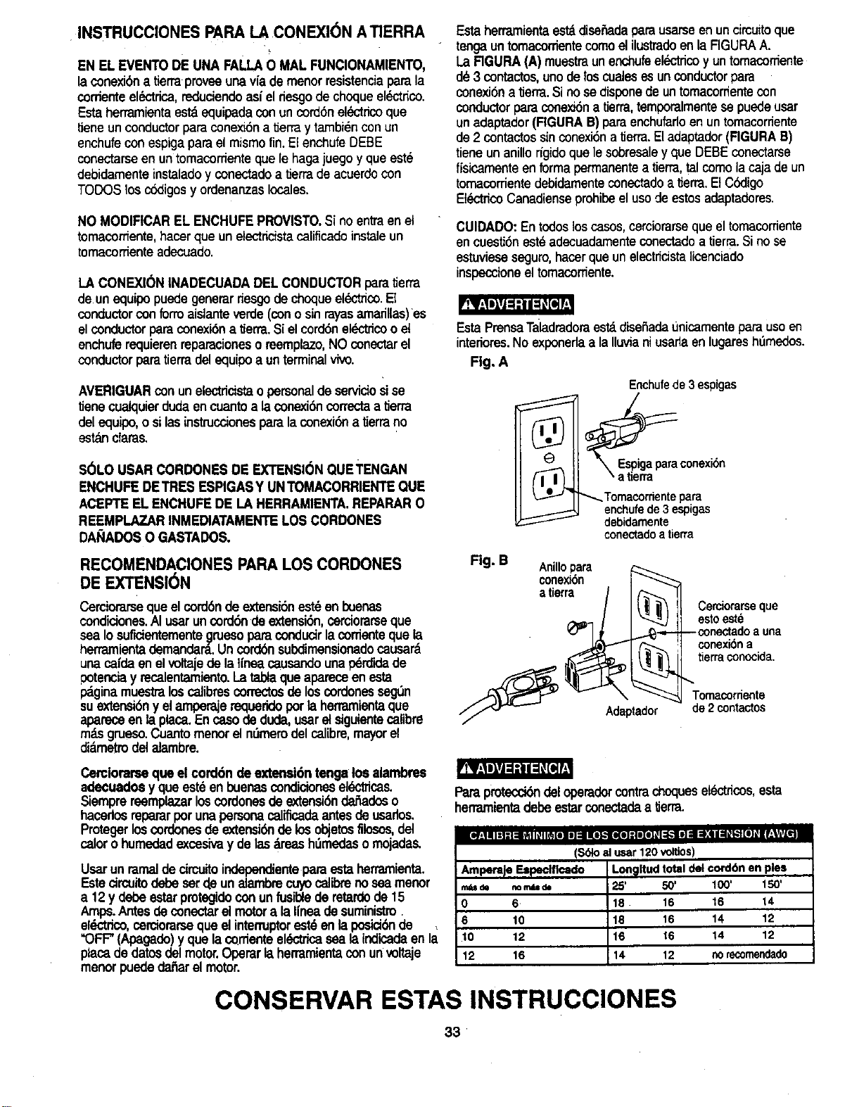
INSTRUCCIONES PAPA LA CONEXI(_N A TIERRA
EN EL EVENTODE UNA FALLAO MAL FUNCIONAMIENTO,
la conexi6na tierraproveeunaviademenor resistenciaparela
corrienteel_'trica, reduciendoasiel fiesgo dechoqueel_-tfico.
Estaherramientaest_equipedaconuncord6nel_ctfico que
tJeneunconductorparaconexi6na tJerray tambi_nconun
enchufeconespigapareel mismotin.ElenchufeDEBE
conectarseen untomacomenteque lehagajuegoyque este
debidamenteinstaladoy conectadoa tJerrade acuerdocon
TODOSlosccktigosy ordenanzaslocales.
NO MODIFICAREL ENCHUFEPROVISTO.Si noentraenet
tomacordente,hacerque unetectricistacaliflcadeinstaleun
tomacorrienteadecuado.
LA CONEXlON INADECUADADEL CONDUCTORparetierra
de unequipopuedegenerarriesgode choqueel#,._"ico.El
conductorconform aislanteverde(conosinrayasamarillas)es
elconductorpareconexi6na tJerra.Sielcord6nel_.'tricooet
enchuferequierenraeparacionesoreemplazo,NO conectarel
conductorparatierradesequipoa unterminalvivo.
AVERIGUARcon unelectdcistaopersonaldese_cio sise
tiene cualquierdudeencuanloala conexi_ correctaa tierra
delequipo,o silesinstruccionesparalaconexi6na tierrano
est_ndares.
SOLOUSAR CORDONESDE EXTENSIONQUETENGAN
ENCHUFEDETRES ESPIGASY UNTOMACORRIENTEQUE
ACEPT1EEL ENCHUFEDE LA HERRAMIENTA.REPARARO
REEMPI.AZAR INMEDIATAMENTELOSCORDONES
DA_IADOSO GASTADOS.
Estaherramientaest_disefiadapera usarseenuncimuitoque
tengauntomacorrientecomo elilustradoenlaFIGURAA.
LaRGURA (A) muestraunenchufeelL_.--tricoyuntomacorriente
d_3 contactos,unodelos cualesesunconductorpare
conexi6na tierra.Sino se disponede untomacorfientecon
conductorpareconex_na tierra,temporalmentese puedeusar
unadaptador(FIGURAB) paraenchufarloen untomacorfiente
de2 contactossinconexi6na tierra.Eladaptador(RGURA B)
tieneunanillofigido quelesobresaley queDEBEconectarse
fisicamenteen formapermanentea tierra,telcomo iacajadeun
tornacorrientedebidamenteconectadoatierra.ElC_ligo
Et_ctficoCanadienseprohibeelusode estosadaptadores.
CUIDADO:Entodosloscases,cerciorarseque eltomacorriente
encuestJ6nest_adecuadamenteconectadoa tierra.Si no se
estuvieseseguro,hacerqueunelectficistalicenciado
inspeccioneeltomacorriente.
EstaPrensaTaladradoraes_ disefiadaunicarnenteparausoen
interiores.No exponedaala Iluvianiusariaen lugareshtimedos.
Fig. A
Enchufede3 espigas
®
_----_ _Tomacordente pare
enchufede3 espigas
debidamente
conectadoatierra
RECOMENDACIONESPAPALOS CORDONES
DEEXTENSION
Cerciorarseque elcordbnde extensi6nest_en buenas
condiciones.AI usaruncordbndeextensi6n,corciorarseque
sea Iosuficientemente_]ruesopareconducirlacordentequela
herramientademandara.Un cord(_nsubdimensionadocausam
unacafda enelvoltajede la tfneacausandounap_rcrldede
petenciay recalentamiento.La tableque apareceen esta
pdgina muestralos calibrescorrectesde los cordonesseg_n
suextensibny el arnpe_e requerido per la herramientaque
aparaceen la place.Enca.sode dude, userel siguientecalibre
m_.sgrueso.Cuanto menor el ndmerodel calibre,mayorel
di_metmdel alambre.
Fig. B _leOxPara
atierra / I _ "[_
/ I/ | I__ 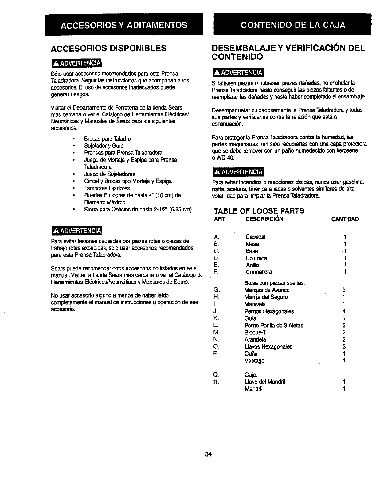
ACCESORIOS DISPONIBLES
S61ousar accesoriosrecomendadosparaestaPrensa
TaladradoraSeguirlasinstruccionesqueacompafiana los
accesoriosEl usode accesoriosinadecuadospuede
generar riesgos
Visitarel Departamentode Ferretedade la tiendaSears
mascercana over elCat&logode HerramientasEIL_tricas/
Neum_,ticasy Manualesde Searsparalossiguientes
accesorios:
BrocasparaTaladro
• Sujetadory Guia
PrensasparaPrensaTaladradora
• Juegode Mortajay Espigapara Prensa
Taladradora
• Juegode Sujetadores
• Cincely Brocastipo Mortajay Espiga
• TamboresLijadores
• RuedasPulidorasde hasta4" (10cm) de
DiametroM_imo
• SierraparaOrificiosde hasta2-1/2"(6.35cm)
DESEMBALAJE Y VERIFICACI6N DEL
CONTENIDO
Sit&itasenpiezaso hubiesenpiezasda_adas,no enchufarla
PrensaTaladradorahastaconseguirlas piezast<anteso de
reemplazarlasdafiadas y hastahaber ¢ompletadeel ensambt&je
Desempaquetarcuidadosamentela PrensaTatadraderay todas
suspartesy vedficadascontralarelacionque est&a
continuaci6n.
Paraprotegerta PrensaTaladradoracontrala humedad,las
partes maquinadashan siderecubiertasconunacapaprotectora
que sedebe removerconun patiohumedecidoconkerosene
o WD-40
Paraevitarinoendiosoreaccionestbxicas,nuncausargasolina,
nafta,acetona,tinerparatacaso solventessimitaresde alta
volatilidadparalimpiarlaPrensaTaladradora.
TABLE OF LOOSE PARTS
ART DESCRIPCI6N
CANTIDAD
Paraevitarlesionescausadasporpiezas rotasopiezas de
trabajorotasexpedidas,s61ousaraccesoriosrecomendados
paraesta PrensaTaladradora.
Searspuederecomendarotrosaccesoriosnolistadeseneste
manuel Visitar latiendaSearsmas cercanao vet el Cat&logod_
HerramientasEl_ctricas/Neumdticasy Manualesde Sears
Npusaraccesorioalgunoa menosdehaberleido
completamenteel manualde instruccionesu operacionde ese
accesorio
A. Cabezal
B. Mesa
C. Base
D. Columna
E. Anillo
F. Cremallera
G,
H.
I
J
K
L
M
N
O
P
Q;
R
Botsaconpiezas sueltas:
Manijasde Avarice
Manijadel Seguro
Manivela
PernosHexagonales
Gu{a
PemoPerillade3 At&tas
Btoque-T
Arandela
UavesHexagonales
Cu_na
W,_go
C_a:
I_lavedelMandril
Mandril
1
1
1
1
1
1
3
1
1
4
1
2
2
2
3
1
1
34
C
D
G H K
, ,.1
L M
N
0
, 0!]
P
Q
35
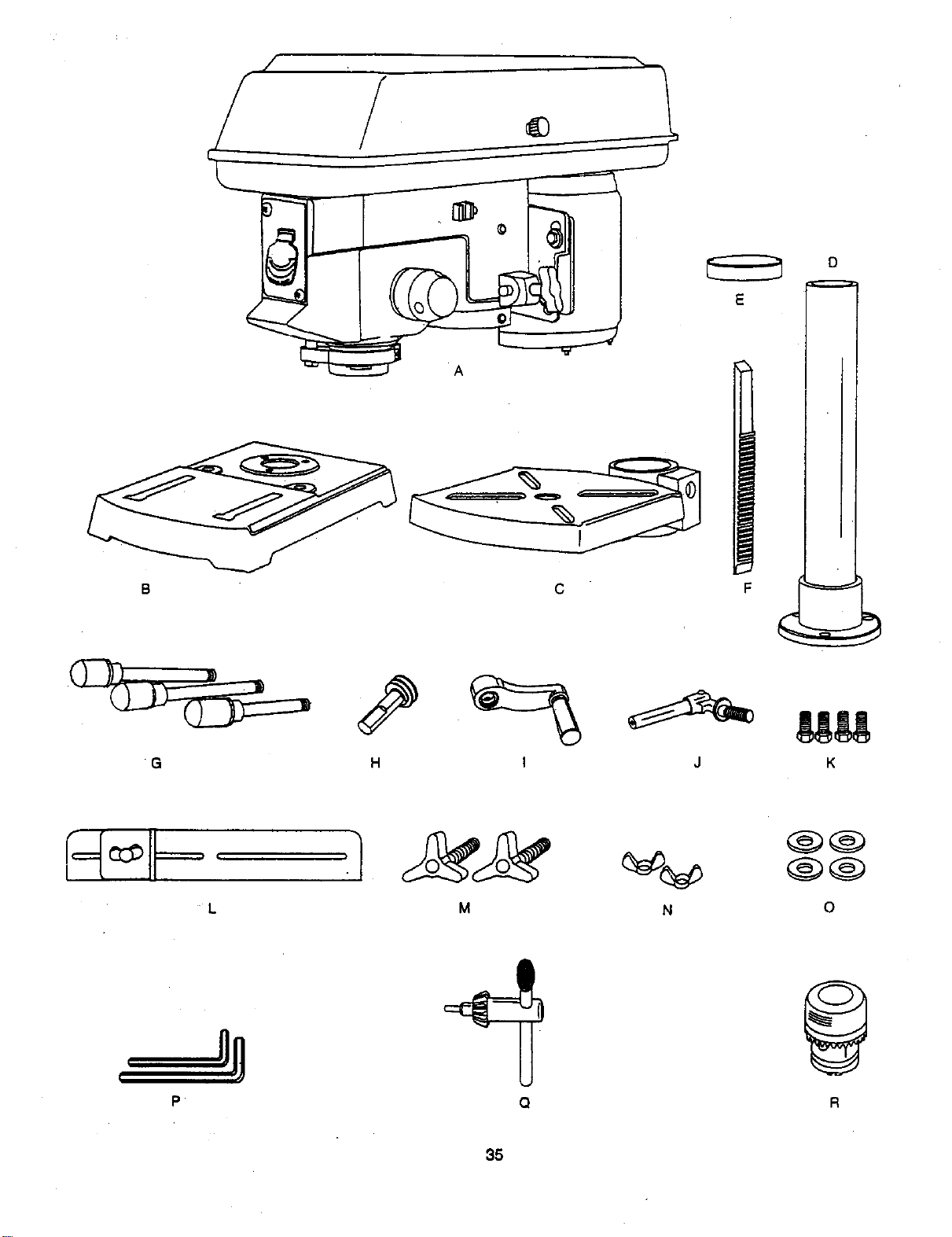
Poleas de
las Correas
Tuerca Superior de Tope Aguja de la escala
Suletador de profundidad
deLCordbn
Manija
Tensionadon
de Coneas
Resorte del
Mecanismo
de Avance
la Co|umna
Escala de
Inclinacibn
Soporte de la Mesa
i de Profundidad
de tope de avance
Cubierta Protectora
Tope de profundidad
Interruptor
\
Seguro del
Soporte
oe Ja Mess
Base
Seguro de
la Inclinacibn
de la Mesa
Mesa
Manijas de Avansa"
Segurode I
Manij
Tensionador
deCorrea
Pernos de
Fijaci6n del
Cabezal
Manivela
de la Mesa
Topedel
Extreme
de la Guia
TopePosteriorde la Gula
36
Columna
Soporte
del a
Columna
BASE- Soportala PrensaTaladradom.Paramayorestabilidad
estdprovistadeorificiosparaempemarla PrensaTaladradomal
piso.(Ver"InstnJccionesde SeguridadEspec_'flsaspara Prensas
Taladradoras').
MATERIAL DE APOYO- Una piezade maderadedesechoque
se colocaentrela piezaquesa trabajay la mesa.La maderade
apoyoevitaquese astillelamaderaque sataladracuandola
broca laatravieza.Tambienevitateladrarla supeffidede la
mesa,
CUBIERTAPROTECTORADE CORREAS- Cubrelaspoleasy
correasdurantetaoperacidnde laPrensaTaladmdora.
TENSION DE LASCORREAS - Refedrsealas secciones:
"Ensamblaje"• "lnstalaci6ny Tensi6nde Correas',
MANilA TENSIONADORA DE CORREAS- Girarlamanija en
elsentidodel relojLoamtensionarlacorreaycontrael sentidodel
relojparaelivlar latensi6n.
SEGURO DE LA MANILATENSIONADORADE CORREAS -
Ajustandolas manijassafijael soportedel motory lamanija
tenelonadoramanteniendota distanciay tensi6ncorrectade la
correa.
ESCALA DE INCUNACl6N DE LA MESA - Muestralosgrades
deindinaci6ndelamesa paralostrabajosdepianoindinado.La
escelaestdmontadaa uncostadodel brazo.
MANDRIL- Sujetalabrocataladradoraocualquierotro
accesoriorecomendadoparareelizarlostt-dbajosdesaados.
LLAVE DEL MANDRIL- Una Ilaveque se autoeyectadel
mandrilcuandose lesuelta.Estaacci6nestddise_fiadapara
evitarque laNavesalgadisparadadel mandrilcuandose active
laherramienta.NousarIlavessubstJtutas.Sisa deteriorao
pierde,ordenarunaIlavenueva.
COLUMNA - Es untuboque conectaelcabezai,lamesay la
baseparafacilitarsualineamientoy mc_imiento.
COLLARiNDE LA COLUMNA - Sujetala cremalleraa la
cotumna.Lacremallerase mantienem6vilen elcollarfnpara
permitirlosmovimientosdel soportede lamesa.
SOPORTE DE LA COLUMNA - Soportalacolumna,guia16
cremalleray proveeorificiosparamontarlacelumnaa
la base.
TUERCAS DETOPE DE LA ESCALA DE PROFUNDIDAD-
Fijaelejea la profundidadsaleccionade.
ESCALADE PROFUNDIDAD- Indica la profundidaddel orificio
que seestdtaladrando.
BROCA- Laherramientaquesa usaenIs PrensaTaladradora
parahacerlosortfidosen lapiezade tmbajo.
INTERRUPTORDELTALADRO-'riene undispositivode
seguro.Estedispositivoestddisafiadopardevitarel usono
autorizadoy posiblementepeUgrosopornifiosy otraspersonas.
Iosertarla I_veen elinterruptory girarlaparaponereltaladroen
operaci6n.
VF:LOCIDADDETALADRADO- Se carnbiacolosandotacorrsa
encualquierade las poleas.Ver laTablade Velocidadesenla
parteintema de la cubierta protectorade las correas.
MANIJASDEAVANCE- Muevenel mandrilhaciaarribay
abajo.Si fuese necosario,se puedenquitarunao dos rnanijas
cuandolapiezade trabajosea deunaforma taninusualque
interlieraconlasmanijas.
GU|A - Se monta en la mesay sirveparaalinearla piezade
trabajoo parahacerperforacionesrepetitJvasenforma rdpide.Es
desmontable.Sasarlacuandointe_eracon losaccesoriosde la
PrensaTaladradora.
SEGUROS DEL CABEZAL - Fijaelcabezalen la columna.
SIEMPRElijarelcadezalenposici6ncon los sagut'oscuandesa
opere16PrensaTeladradora.
CREMALLERA - Funcionaencombinaci6nconel mecanismo
de engranajes.Sirveparefacilitaria elevaci6nde la mesa
operandoa manola manivelade la mesa.
REVOLUCIONESPOR MINUTO(R.RM.)- Eln_memde
vueltascompletasqueunobjetogiratoriode enunminuto.
VELOClDADDEL EJE - LasR.RM.deleje,
TAPA DEL RESORTE - Regula la tension del resorte de la
mort_ja,
SEGURO DEL SOPORTE DE LA MESA - AIajustartoseguros
se ajustaelsoportede la mesaa lacolumna.Siempretenerlo
puestocuandosa operela PrensaTaladradera.
MESA - Proveeunasuperfidede trabajoparaapoyarla pieza
de trabajo.
PERILLA DESEGURO DE LA INCUNACI(_NDE LA MESA -
Fijala mesaencualquierdngulode indinaci6nde 0°a 45°.
MANIVELA DE LA MESA - Sirveparasubiry bajarlamesa.
Giradaen elsentidodel relojparaelevarla mesa.Debesoltarsa
elsegurodel soporteantasdeoperala manivela.
SEGURO DE LA MESA - Fijala mesaen posic_ndespudsde
colosarlaencualquierposicibn.
SOPORTE DE LA MESA - Se desplazaenlacolumnapara
soportarelbrazode la mesay la mesa.
PIEZA DE TRABAJO - Elmaterialquese teladra.
37.
INSTRUCCIONES PARA EL ENSAMBLAJE
Potsupropia seguridad,nuncaenchufareneltomacorriente
hasta haber completadotodoslos pasos del ensamblajela
regulaci6n,y hasta haber leido y entendidolasinstruccionesde
segufidad y operaci6n.
HERRAMIENTASNECESARIAS
Desarmador Piano
Llave combinada
I ...._ i [ ] I i k i ! i
W
Escuadra
Llaveregu_ablede8"y 10"
_.....l E I !:;i',;ii: :
Escuadra combinada
Llave ratchet con dado
de 23 mm
' LaPrensaTpladradoraesmuypesaday pardensamblarseen
lorma seguraDEBElevantarseconla ayudade 2 personaso
m_s.
SOPORTE DE LA COLUMNAA LA BASE(RG. A)
1. Colocarla base(1) enel piso.
2. Colocarlacolumna(2) enla basealineandolosorificiosen
elsoportede lacolumnaconlos orificiosdelabase.
3. UbicarlosoJatropernoshexagonaleslargos(3) enlabolsa
conpiezas sueltas.
4. Colocarunpemoencadaorifidodelsoportede lacolumna
y de la base.Ajustarcon unaIlaveregulable.
Fig. A
I
2
3
Ens•mbl•je de la columna • I• meu (Fig. B • F)
1.Ubicarelejedetomillosinfln,la maniveladela mesay el
segurodelsoportedela mesadela bolsade piezassueltas.
2. IntroducirelejedetomiUosinfln(1) en eloriflc_o(2)par• la
manivel•delamesa desdelaparteinteriordelsoporte(3).
Asegurarsedequeel ejedetornitlosinflnengraneconel
engranajeinterior.
3.Introducirlamanijadelsegurodelsoportede lamesa(4) en
elorificiodela parteposteriordelmismo.Ajustar.
Nora:Paramayordaridad,enlailustracibnnoseha incluidoI•
mesadelsoporte.
Fig. B _ 1
4. Colocarlactemalleraensulugardentrodelsoporte(3) dela
mesa,esegur_ndesade que elejedetomillosinfln(1)en la
parteinteriordelsoportequedeengranadoconlosdientesde
la cmmallera.
Fig. C
38
5. Colocarlaunidadde soportedelamesajuntoconlacremallera 8. Instalelamanivela (9) enelejedeltomillosinfln(1) enelladodel
( 3, 5) enlacolumna, soportedelamesa (3).
6. Hacerque laparteinferiorde lacremallera(5) encajeenel borde 9.Alineelaparteplanadelejeconeltom,inpdsionero(10)de la
menivelay aprieteeltomillocon una,ave hexagonal.
delsoportede lacolumna(6). Ajustelamanijadel sagurodel
soportede lamesa (4) parefljarla unideddelsol)odedelamesa
en la co(umna,
4
3
6
Fig. D
Fig. F
INSTALACIONDEL CABEZAL(FIG.G)
7. Instaleelanillo(7) sobreelextremosuperiordelacremallera(5),
en lacolumna.
IMPORTANTE:NO DEBEmeterporcompletolaparteinferiordel
anillosobrelepartesuperiorde lacremallera.ASEGURARSEde
que lapartesuperiorde lacremalleraquededebajodelaparte
inferiordel aniliny quehayasuficienteespaciolibreparaque la
cremallerapuedagirarlibrementealrededorde lacolumna.
Aprleteet pemo_sionero (8).
CUIDADO:Pareevitardaf_arlacolumnaoelanillo,NOAPRIETE
EXCESIVAMENTEelpemopdsionero.
Elcabezaldela PrensaTaladraderaesmuy pesaclay para
ensamb/arseenforma seguraenlacolumnaDEBElevantarse
conlaayudede 2 PERSONASO M._S.
1. Levantarelcabezal(1)cuidadosamentesobrelacolumna(2)
y deslizarlaenlacolumna.Cerciorarseque el sabezalse
deslicetanabajoen lacolumnacomosea posible.Alinearel
cabezalconlabase.
2. Usandouna,ave hexagonal,ajustarlosdospernosde
fijacibn(3) enellado derechodelcabezal.
Fig, E
5
Fig. G
1
39
|NSTALACIONDELAS MANIJASDE AVANCE(RG.H)
1. Ubicarlastresmanijas deavanceenlaboI_. de piezas
sueltas.
2. Insertery enroscartasmanijas(1) enlosorificios
roscades(2)ctetcubo(3).AjusWr.
Fig. H _ 3 /
INSTALACIONDEL MANDRIL (FIG. I, J and K)
1. Limp|atel orificioahusadoen elmandril(1) conun
paso,m_.
2. LimpiarJassupe_ciesahusadesde4v_stago(2)
CUIDADO:Cerc_ommquenohayancuerpes
adheridosalas superficies.Lapartfculade tJerran_s
peque_ enestassuperf'_es evitardqueel manddlse
asienteapropiedarnente.Estohar_qued rnandritdet
taladroy _ broc.ase bard:_een.Siel or_ aht,mado
estuvieseextremadamentesucio,.emplearunsolvente
({mpi_dor.
Fig. I
,
4,
5,
Bajarel ejegirandolasmanijasde avance (3)contrael
sentiUodelreloj.
Colocareln_nddl(1) en e!v_L_tago(2).Golpeado
levementeparecerelorarsequese asJente.
Abdrlasmandibulasdel mandril(1)girandotamangadel
n_ndrilen elsen_dodel reloj.Pareevitardefios,cerciorarse
quelasrnand_ulasest6ncompletamentemtra_dasdentro
delmandril.
Fig, J
=_==¢====
I .3
.
Usandounmazodecauchoo martilloconcabezade
pl_co o unbloquede maderayun martil_o,go_peado
levementehada arribahastaque enca)eenposicibnen
eleje.
FlCJ. K
COMO INSTALAR LAPRENSATALADRADORAA LA
SUPERFICIEDETRABAJO.(FIG. L)
1. Siseinstalalaprensataladradorasobreunamesade
trabajo,es prefer|hieunamesademaderamacizaen lugar
deuntablerode maderacontrachapada,paradisminuirel
nivelderuidoy devibracibn.
2. Debehaberseperforadolosodficiospreviamenteen la
superficiedeapoyo.
3.Conlaherramiente,NOse suministralaspiezasde
ferreter|aparasuinstalacibn.Debe utilizarse|as piezasde
ferreterfacomose muestraenlailustmcibn:
Fig. L !
I. Basedefaprensataladradora ,_J
2. Pemo
3. Arandelaplane _[
4,
Arandeladecauch_
G. Supe_ciede trabajo|
6. Arandefaplane. [
7. Arande|adepresibnI
8.
Tuercahexagonal Vi/ \_
Contratuerca \ .
9.
\
5
I
I
I
4O
ENSAMBLAJE DE LA GUIA (FIG. M)
1. Decidir cuSI es la posicibndeseada de la gula (1).
2 Alinear los orificiosde instalacibn de la gula con las ranuras
de la parte superiorde la mesa.
3. Colocar una arandela (2) sobre el extremo roscado de la
perilla (3). Introducir la perflla a trav/_sdel orificiode instalacibn
de la gula y la ranura de la mesa.
4. Colocar una arandela y una tuerca de mariposa (4) en la perilla,
desde la parte inferior de la mesa.
5. Repetir el procedimiento para la otra periUay ajustarlas.
Fig. M
REGULACION DE LA PRENSA
TALADRADORA
CUIDADO:T_xloslosajustesy regulacionesnecesar_aspara la
operaci_h-Idela PrensaTaladradorabansidehechasenla
f_bdca.Debidoa_usey desgastenormal,ocasionalmente
podrfanrequefirsealgunosreajustes.
Para evitarlesiones debidasa un arranqueaccidental,SIEMPRE
cerciorarsaque el interruptoreste enla posici6nOFF (Apagado)
y desconectaretenchufedel tomacordenteantesde hacer
cualquier regulaci6n.
ALINEAMIENTODE I.ASPOLEASDELASCORREAS(FIG.N)
Abrirla cubierta protectorade lascorreasenla Prensa
Taladradora.Verificaretatinearnientode laspoleas,conunaregla
(5), escuadra,nivelopedazode maderarecta.Colocarel horde
de lareglaa Io largode lapartesuperiordelaspoleas.Sitodas
laspoleasestuviesendesalineadas:
1. Ativiarlatensi6ndelas correasaflojandolos segurosde las
manijastensionadoras(4) decorreasa cadaladodel
cabezal,desenganchandolasmanijastensionadoras(1)
decorreas.
2. Aflojar1astuercas(2) de montajedel motor.Subiro bajarel
motor(3) hastaque laspoleasquedenalineadas.
3. Ajustarlastuercas(2)de montajedelmotorusandouna
llaveregulable.
NOTA:Paraevitartraqueteosy otros ruidos,elcascodel
motor no debetocar la parteinfedordel cascodela correa.
4. Volvera ajustarlascorreasgirandoen elsentidodel relojla
manijatensionadora(1), hastaque la correase deflexione
1.2cm (1/2")al presionarlacorreaenelmedio.
NOTA:Referirsea la tab_aqueseencuentraenla parte
interiorde la cubiertaprotectorade lascorreas,paraobtener
las posicionesde lasIx)leas recomendadasparalas
distintasvelocidadesde taladrado.
5. Ajuatar lossaguros de la manijatensionadora(4), girandolos
enelsentidodelreloj.
NOTA:Cuandolascorreasestdnnuevas,puedeserdiffcil
movedas.Conformese usala mdquina,lascorreasse
vo_verdnrnaseldsticasy serdnmasfdcilesderegular.
N
41
4
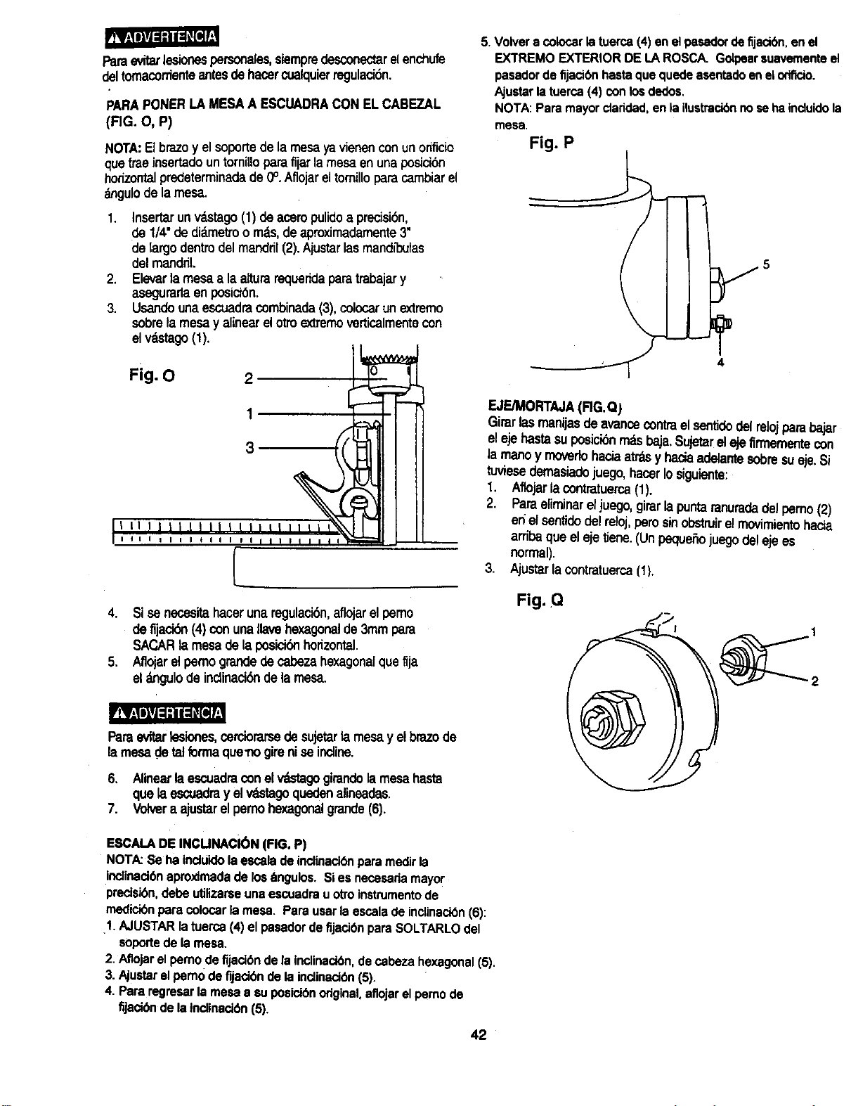
Pareevitarlesionespersonales,siempredesconectarelenchufe
deltomacorrienteantesdehasarcuelquierregulacion.
PARAPONERLA MESA A ESCUADRACON ELCABEZAL
(RG. O, P)
NOTA:Elbrazoy el soportede la mesayavienenconunorificio
que treeinsertadountomilloparefijarla mesaen unaposicidn
horizontalpredeterminadade0°.Aflojareltomilloparecambiarel
_ngulodelamesa.
1. Inserterunvdstago(1) de aceropulidea precisidn,
de 1/4"de di&metroo rr_s,deaproximademente3"
de largo dentrodelmanddl(2).Ajustarlasmandl'bulas
del mandril.
2. Elevarla mesaa la alturarequeridaparetrabajary
asegurartaenposicldn.
3. Usandounaescuadracombinada(3),colcoar unextremo
sobrela mesay alinearelotroextremeverticalmentecon
elv_stago(1),
Fig. O 2
5.Volvera colocarlatuerca(4) enelpasadordefijadbn,enel
EXTREMOEXTERIORDELA ROSCA. Golpearauavernerrt_el
pasadorde fijacibnhasteque quedeesentadoenelorificlo.
Ajustarla tuerca(4) con losdedos.
NOTA:Paremayorcladdad,enla ilustracibnnose hainduidola
mesa.
Fig. P
yo
1
3
I I I I I
4. Sisa necesitahacerunaregulaci6n,aflojarel pemo
de fijacibn (4) conunaIlavehexagonalde3mmpare
SACARlamesade laposici(_horizontal.
5. Aflojarel pemogrendede cabezahexagonalque fija
el_gulo de indinaci6ndela mesa.
r!_lililli_iiiiil[lll
Pareevitarleelones,cerciorarsede sujetarlamesa yel brazode
la mesade telforma que-nogirenisa incline.
6. Alinearlaescuadraconelv_go girendela mesahaste
quelaescuadrey elv_stagoquedenalineadas,
7. Volvera ajustarelpemohexagonalgrande(6).
EJE/MORTAJA(RG.Q)
Girarlasmanijasdeavancecontraelsentidedelrelojparebajar
elejehastesuposicibnm_ baja.Sujetarelejefirmementecon
la manoy moverlohaciaatr_sy haciaadelantesobresueje.Si
tuviesedemesiadejuego,hacerIosiguiente:
1. Aflojarlacontratuerca(1).
2. Pareeliminareljuego,girarla puntaranuradedel perno(2)
en"et sentidodel reloj,perosinobstruirelmovimientohac_a
arribaque elejetiene.(Unpeque_ojuegodel eje es
normal).
3. Ajustarlacontratuerca(1).
Fig. Q
ESCALADEINCUNACi6N (FIG. P)
NOTA:Se hainoluido laescalade inclinacibnparemedirla
indinadbnaproxJmedadelos_ngulos. Sies necesariamayor
predsibn,debe utilizareeunaescuadrauotroinstrumentode
medicibnparecolocar lamesa. Pareuserlaescaladeinclinacibn(6):
.1.AJUSTARlatuerea(4) elpasadordefijacJbnpareSOLTARLOdel
soportede lamesa.
2. Aflojarelpemode fijadbndela inclinaci6n,decabezahexagonal(5).
3. Ajustarelpemode fijadbnde laindinacibn(5).
4. Pareregresarlamesaa aupoeldbnoriginal,aflojarelpemode
fiJaci6nde latndinaci6n(5).
42
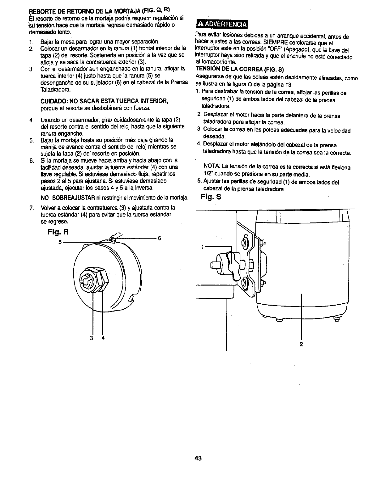
tI_IESORTEDE RETORNODE LA MORTAJA(FIG. Q, R)
Elresole de retomodela mortajapodriarequenrregulacibnsi
"S:utensibrthacequela mortaja regmsedemasiado _pido o
demasiadolento:
1. Bajarlamesa paraIograrunamayorsaparaci6n.
2. Colocarundesarmadoren laranura(1)frontal inferiordela
tapa(2) delresorte.Sostenerlaenposiciona la vez quese
aflojay sesacalacontratuercaexterior(3).
3. Coneldesarmadoraun enganchadoen la ranura,aflojarla
tuercainterior(4) justo hastaque la ranura(5) se
desenganchede su sujetador(6) en elcabezalde laPrensa
Taladradora.
CUIDADO:NO SACAR ESTATUERCA INTERIOR,
porqueel resortese desbobinaraconfuerza.
4. Usando un desarmador,girarcuidadosamentetatapa(2)
del resorte contrael sentidodel relojhasta que lasiguiente
ranura enganche.
5. Bajarla mortaja hasta su posici6n m&sbaja girandola
manijade avancecontra el sentidodel reloj mlentrasse
sujeta latapa (2) del resorte en posici6n.
6. Si la mortaja se muevehacia arribay hacia abajocon la
facilidaddeseada,ajustarla tuerca est_.ndar(4)con una
Ilave regulable,Si estuviesedemasiadofloja,repetirlos
pasos 2al 5 para ajustarla.Si estuviesademasiado
ajustada,ejecutar los pasos 4 y 5 a la inversa.
.
Paraevitarlesionesdebidasa unarranqueaccidental,antesde
hacer ajustesalas correas,SlEMPREcerciorarseque el
interruptoreste en la posicion"OFF"(Apagado),que laIlavedel
interruptorhayasideretiraday que el enchufeno estd conectado
a]tomacorriente.
TENSI(_NDELA CORREA(FIG. S)
Asegurarsede quelaspoleasest_ndebidamente alineadas,como
se ilustraen la figuraO de lap_gina13.
!. Paradestrabarlatensibndelacorrea,aflojarlasperillasde
saguddad(1) deambosladosdelcabezaldela prensa
taladradora.
2. Desplazar el motor hacia la parte delantera de la prensa
taladradora para aflojar la correa,
3. Colocar la correa en las poleas adecuadas para la velocided
deseada.
4. Desplazar el motor alej_ndolo del cabezal de la prensa
taladradora hasta que la tensibn de la correa sea la correcta,
NOTA:Latensibnde lacorreaes lacorrectasiest_ flexiona
1/2"cuandose presionaensupartemedia.
5.Ajustarlas perillasdesagurided(1) deambosladosdel
cabezaldela prensataladradora.
NO SOBREAJUSTARnirestringirelmovimientode la mortaja. Fig. S
Volvera colocarla contratuerca(3) y ajustarlacontra la
tuercaest_ndar(4) paraevitarque la tuerca estandar
se regrese,
3
4.3
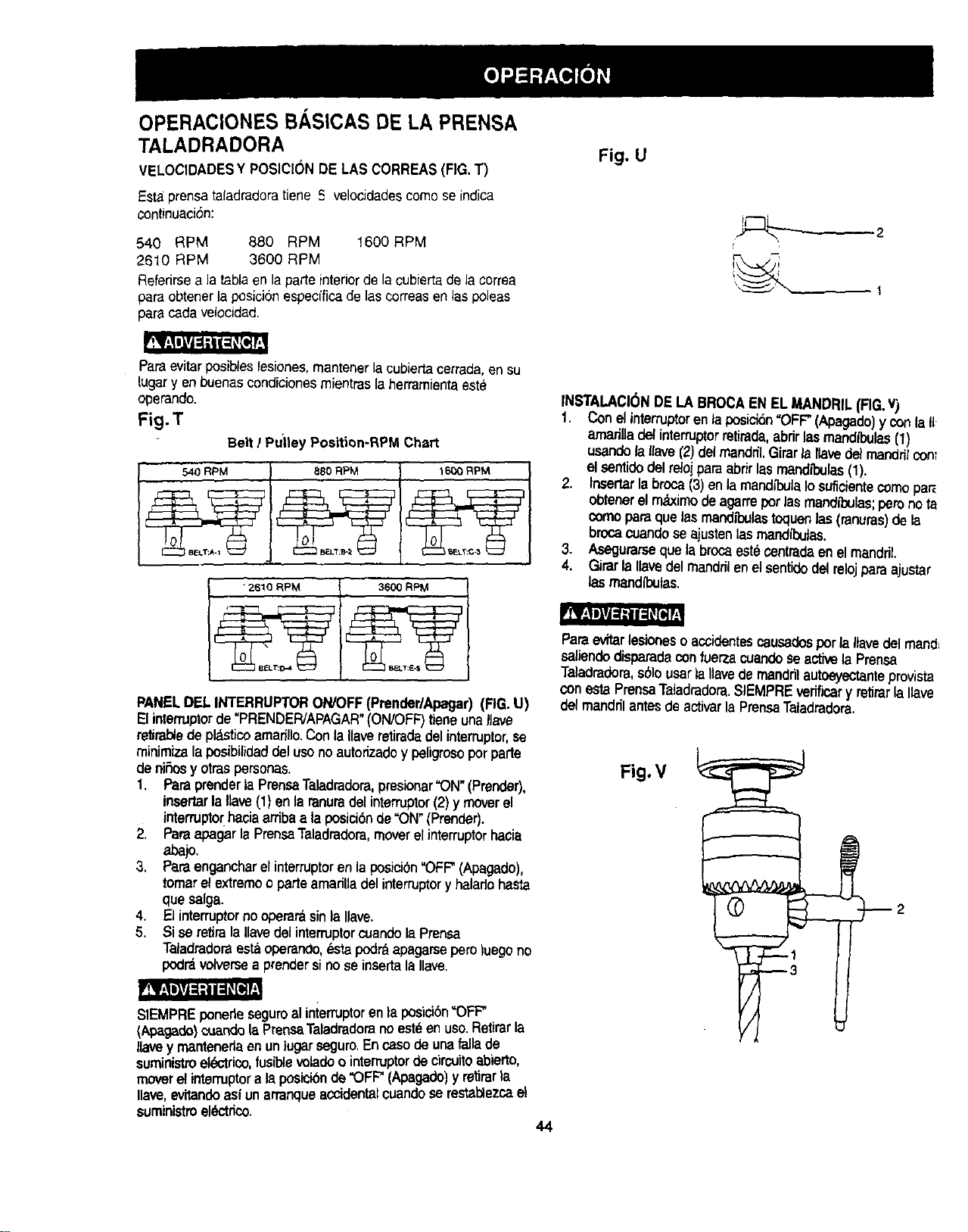
OPERACIONES BASICAS DE LA PRENSA
TALADRADORA
VELOCIDADESY POSICR3NDE LAS CORREAS(FIG.1")
Estaprensatafadradoratiene 5 velocidadescomose indica
continuaci6n:
540 RPM 880 RPM 1600RPM
2610 RPM 3600 RPM
Referirsea la tabla en la parte interiorde la cubierta de la correa
paraobtenerla posici6nespecfficade lascorreas en las poleas
para cadavelocidad.
Fig. U
t
q i
Paraevitar posibleslesionee,rnantenerla cubiertacerrada,en su
lugar y enbuenascondicionesmientraslaherramientaeste
operando.
Fig.T
Belt / Pulley Position-RPM Chart
540 RPM 880 RPM 1650 RPM
3600 RPM
PANELDEL INTERRUPTORON/OFF(Prender/Apagar) (FIG.U)
El interruptorde "PRENDER/APAGAR"{ON/OFF)tieneunaIlave
retirablede pl&sticoamarillo.Conla Uaveretiradadelinterruptor,se
rninimizalapoeibitidaddelusono autorizadoy peligrosoporparte
de niSosy otraspersonas.
1. Paraprenderla PrensaTaladradora,presionar"ON"(Prender),
insertarlaIla_e(1)en laranuradel interruptor(2) y moverel
interrupto(haciaarribaa laposici6nde =ON"(Prender).
2. Paraapagarla PrensaTaladradera,moverelinterruptorhacia
abaio.
3. Paraenganoharelinterruptoren lapoeici0n"OFF"(Apagado),
tomarelextremoo parteamariUadelinterruptoryhalariohasta
que salga.
4. El interruptornooperarasinlaIlave.
5. Si se retiralaIlavedelinterruptorcuandolaPrensa
TaladradoraestaopemnOo,estapodrbapagarseperoluego no
podr_volversea prendersinose insertalaIlave.
SIEMPREponede eeguroal interruptoren la posid6n"OFF"
(Apagade)cuandola PrensaTaladradorano est_enuso. Retirarla
Ilavey mantenedaen un tugarseguro.En caso de unafallade
suministroel_ctrico,fusible,,_ladoo interruptorde circuiteabierto,
moverel interruptora la posicionde "OFF"(Apagado)y retirarla
Ilave,evitandoasi unarranque accidentaleuandose restablezcaet
suministroel_ctdco.
INSTALACI(_NDE LA BROCAENEL MANDRIL(FIG.v)
1. Conelinterruptoren taposici6n"OFF"(Apegado)yconla U
arnariUade/interruptorretirada,abrirlasmandibulas(1)
usandolaIlave(2) del mandril,Girarla Ilavedel mandrilcon_
el sentidedel relojparaabrirlasmandN_ulas(1).
2. Insertarla broca (3) en la mandibulaIosuficientecomopar_
obtenerel maxirnode agarre/)or lasrnandll_ulas;pero no ta
comopera que lasrnandJl_lastoquenlas(ranuras)de la
brocacuandose ajustenlasrnandibutas.
3. Asegurarseque la brocaestecentradaenel mandril.
4. GirarlaIlavedel mandrilenel sentidodelrelojparaajustar
lasmandibulas.
Paraevitarlesioneso accidentescausadosporla Itavedel rnand=
saliendedisparadeconfuerzacuandose activelaPrensa
Taladradora,s61ousarla navede mandrilautoeyectanteprovista
conestaPrensaTaladradora.$1EMPREverificary retirarla Ilave
del mandrilantesdeactivarlaPrensaTaladradora.
Fig. V
_2
44
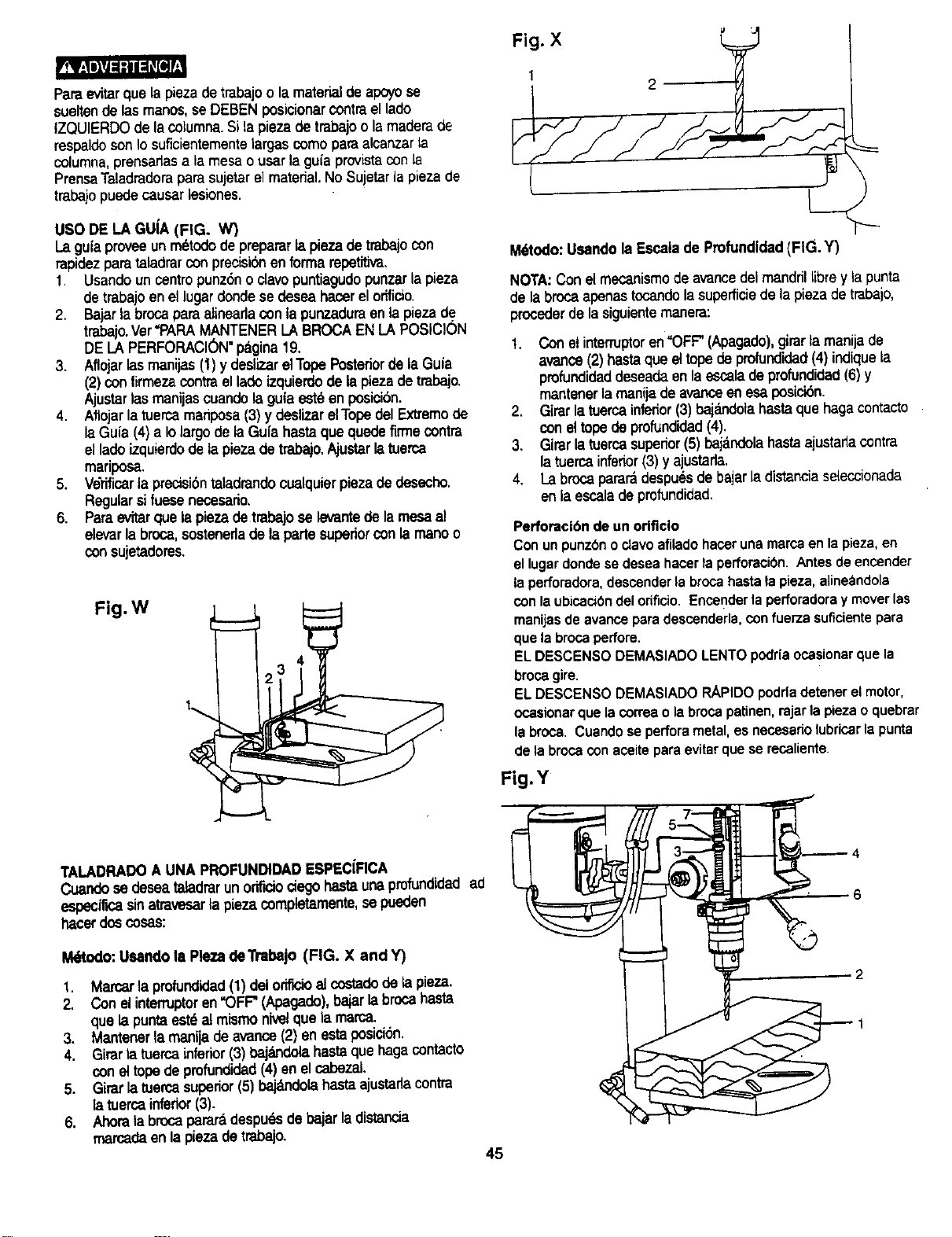
Pare evitarque la piezade trabajoo la materialde apoyose
sueltende las manos,seDEBEN posicionar contrael lade
IZQUIERDOde la columna.Si la piezade trabajoo la maderade
reepaldoson Iosuflcientementelargas como pare alcanzarla
columna,prensarlasala mesa o usar la gula provistacon la
PrensaTaladradorapare sujetar el material.No Sujetarla piezade
trabajopuede causar lasiones.
USO DE LA GUIA (FIG. W_
La gulaprovee unm6todo de preparerla pieza de trabajocon
rapidezpare taladrarcon precisibnenforma repetitive.
1. Usando un centro punz6no davo puntlagudopunzarla plaza
de trabajoen el lugar dondese desea hacerel orificio.
2. Bajar la brocapare atineadaconla punzaduraenla pieza de
trabajo.Ver"PAPAMANTENERLA BROCA ENLA POSIClON
DE LA PERFORACION"pagina 19.
3. Aflojarlasmanijas (1)y deslizar elTope Posteriorde la Gula
(2)con firmezacontra el lade izquierdode la piezade trabajo.
Ajustar lasmanijas coandola gula est6 en pesicibn.
4. Aflojar la tuerca mariposa(3) y deslizar elTopedel Extremode
la Gula (4) a Iolargo de la Gula haste que quedefirme contra
elladeizquierdode la piezade trabajo.Ajustarla tuerca
mariposa.
5. Vdrificarla precisi6ntaladrandocualqular piezade desecho,
Regularsifuesenecesario.
6. Pareevitarque la piezade trabajo se levantede lamesaal
elevarle broca,sostenerlade la parle superiorcon la manoo
consujetadores.
Fig.W
Fig. X
1
2
M6todo:Usandola Esoalade Profundidad(FIG. Y)
NOTA:Con elmecanismode avancedel mandrillibre y la punta
de la broca apenastocandola superficiede la plazade trabajo,
procederde la siguientemanera:
t. Con elinterrupteren"OFF"(Apagado),girar la manijade
avarice (2) hasteque eltope de profundidad(4) indiquela
pmfundidaddeseadeen la escalade profundidad(6) y
mantenerla manijade avariceen esaposici6n.
2. Girar la tuerca inferior(3) bajandelahasta que haga contacto
con eltopede profundidad(4),
3. Girar la tuerca supedor(5) bajdndola hasteajustarlacontra
la tuerca inferior(3) y ajustarla.
4. La brocapararadespuds de bajar la distanclaseleccionada
en la escala de profundidad.
Perforaci6n de un odficlo
Con un punzbn o clavoafilado hacer una marce en la pieza, en
el lugar donde se desea hacer la perforacibn, Antes de encender
la perforadora, descender la broca hasta la pieza, aline_ndola
con la ubicaci0n del orificio. Encerlder la perforadora y mover las
manijas de avance para descenderla, con fuerza suficientepara
que la broca pedore.
EL DESCENSO DEMASIADO LENTO podria ocasionar que la
broca gire.
EL DESCENSO DEMASIADO RAPIDO podda detener el motor,
ocasionar que la correa o la broca patinen, rajarla pieza o quebrar
la broca. Cuando se perfora metal, es necesario lubricer la punta
de la broca con aceite para evitar que se recaliente.
Fig.Y
TALADRADOA UNA PROFUNDIDADESPECIFICA
Cuandosedeseataladmrunorit'_ociegohastaunaprofundidadad
espedficasinetravesarla plazacompletamente,sepueden
hacer doscosas:
I_o: Usando la Pleza deTrabajo (FIG. X and Y)
1. Mercerla profundidad(1) del orificioal costa,do dela pieza.
2. Con el intemJptoren"OFF"(Apagado),bajarla brocahaste
que la punta est6 almismonivelquela mama.
3. Mantenerla manijade avarice (2) en esta posicion.
4. Girarla tuema inferior(3) bajdndola haste que haga contacto
con el tope de profundidad(4) en el cabezat.
5. Girarla tuercasuperior(5) ba_uldolahasta ajustadacontra
la tuercainfedor(3).
6. Ahorala brocapararddespuds de bajarla distancia
marcadaen laplazadetrabajo,
45
4
6
2
QUITAR EL PORTABROCAS (FIG. Z)
1. Con el interruptor en =OFF" (Apagado), abrir las
mandibulas del mandril girando la manga del mandrill
• contra el sentido del reloj.
2. Golpear levemente mandril (1) con un martillo con cabeza
de pl_stico, hasta que el mandril y elevacibn.
NOTA: Colocarunamano debajode mandrilparaagarrarlo
Cuandocajga.
Fig. Z 1 _'_
Por su propia seguridad colocar el interruptoren la posicibn
"OFF" (Apagado) y desconectar el enchufe del tomacorriente
antes de desmontaje del nandril y instalacibn mandril.
INSTRUCCIONES BASICAS PARA LA OPERACI(_N
Seguirestasinstruccionespara operarlaPrensaTaladradoray
Iograrlosmejoresresultadosy minimizarlaposibilidadde
lesiones.
FOrsupropiaseguridad,siempreobedecerlasINSTRUCCIONES
deseguridadque seindicanaquiyen laspaginas3,4 y 5 der
manualde instrucciones.
PROTECCI(_N DEL OPERADOR
b) Siempreque seaposible,cotocarLAPIEZADE
TRABAJOdetalmaneraquehagacontactoconla parte
izquierdadela columna.Sifuese muy cortaosila mesa
estuvieseinciinada,usarla guiaprovistaosujetarlaen
forma seguraa lamesa,usandolasranuras.
c) Cuandose useunaprensasujetadorapara
taladro,siempreasegurarlaa lamesa.
d) Nunsatrabajarsosteniendola piezaquesetaladrasblo
conla manoy sinsujetarlaa lamesa,exceptoalpulir.
e) Fijarelcabezalenforma seguray elsoportea la
columna,elbrazodelamesaalsoportey la mesaal
brazode lamesaantesdeoperarla PrensaTaladradora.
f) Nuncamoverelcabezalnilamesamientrasla
herramientaesteenoperacion.
g) Antesde iniciarlaoperacion,operarelmotorenforma
lentaparaasegurarsequeni labrocanilasdemds
herramientascortantesse bamboteenovibren.
h) SiunapiezadetrabajosobresaLede hamesadetal
maneraquecaigaose inclinesinose sostJene,sujetada
a lamesao proveerunsoporteauxiliar.
i) Parasostenerla piezadetrabajoenforma adecuadaen
j) UsarlaVELOCIDADDE EJErecomendadaparala
oderacibnespecfficay mater_ala taladrar.Refedrseal
panelentaparteinteriorde ia cubiertadelaspoleaso
a latablaque se indicaa continuaci6nparaobtener
informaci6nsobrelasvelocidadesdepedoracibn.Para
ootenerinformacibnsobrelosaccesorios,refedrsealas
instruccionesprovistasconcadaaccesorlo.
5) Nuncasubirsea lamesade laPrensaTaladradora,podr{a
romperseo hacerquela herramienta.caigasobreunomismo.
6) Colocarel interruptordelmotoren"OFF"(Apagade)y guardar
la Uavedelinterruptorcuandose deje la PrensaTatadradora.
7) Paraevitarlesionesdebidoa piezasarrojadaso contacto
con laherramienta,no realizarlaboresdetrazado,
ensamblajeni preparacibnsobrela mesacuandola
• herramientaesteen operaci6n.
Nousarropasueffa,guantes,collatesnijoyasparaevitarser
atrapadoporlaherramienta.Siempreataretpelolargohaciaarras.
1) Sialgunapiezade la PrensaTaladradoraestuviesefaltando,
rota o da5ada,o no opera debidamente;dejarde operartade
mmsdiatohasta que esapieza hayasidereparada
apropiadamenteo reparada.
2) Nunsacolocar losdedosen una posicibntal que puedan
entrarencontacto conla broca ocon cualquierotrapieza
cortante.La piezade trabajopodda moversee la manc,
podria resbalarseinesperadamente.
3) Seguirlasinstrucoionesal pie de la letraalregular latension
delresortede la mortajaparaevitarlesionescausadaspor
piezaspropulsadasporel resorte.
4) Paraevitarque la herramientaarranquelapiezadetrabajo
de lasmanos,que salgadespedidao la herrarnientala haga
girarose rompa,siempresujetarla piezade trabajo
adecuadamentecomosigue:
a) Siemprecolocar MATERIALDE APOYO(usadobajola
piezade trabajo)detalmaneraqueseapoyeenellado
Izquierdode la columna,ousarla guiaprovistay un
sujetadorparasostenerlaspiezaspeque_as.
46
DRILLING SPEED TABLE (rpm)
Matedal
Wood Alum.Zinc,Brass
3600 3600
DrillBit
Dlam,
(Inches)
1/16
1/8
3/16
1/4
5/16
3/8
1/2
2610
2610
1600
880
Iron,Stul
3600
2610
1600
880
54O
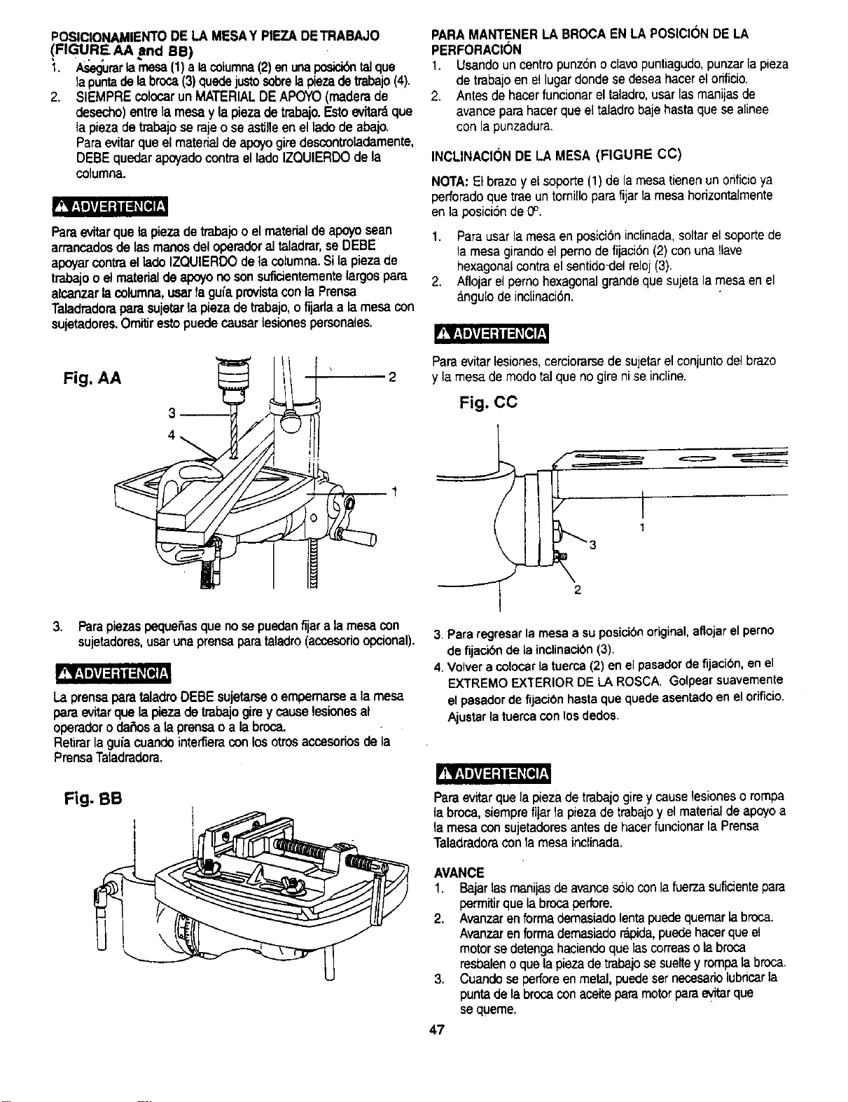
PQSICIONAMIENTODELA MESAY PIEZADETRABAJO
!FIGUREA, A arid Be)
I. Asegurarlarnesa(1)a lacolumca(2) enunaposick_ntalque
la puntadelabroca(3)quedejustosobrelapiezadetrabajo(4),
2, SIEMPREcolocarunMATERIALDEAPOYO(maderade
desecho)entrelamesa y la piezadetrabajo.Estoevitardque
la piezadetrabajose rajeose astJlleeneiladode abajo,
Paraevitarqueel materialde alx_yegiredescontroladamente,
DEBE quedaraim/ado oontraellado IZQUIERDOde la
columna.
_._EIiITJ-dt_PJ_dl
Paraevitarquela piezadetrabajoo el materialde apoyosean
arrancadosde las manosdel operadoral taladrar,se DEBE
apoyarcontraellado IZQUIERDOdelacolumna.Silapiezade
trabajooel materialdeapoyono sonsuficientementelargospara
alcanzarlacolumna,usarfagufaprovistaconla Prensa
Taladradoraparasujetarla piezadetrabajo,o fijadaa lamesa con
sujetadores.Omitirestopuedecausarlesiones personales.
PARAMANTENER LA BROCAEN LA POSICI(3NDELA
PERFORACI(_N
1. Usandouncentropunzonoclavopuntiagudo,punzarlapieza
de trabajoenellugardonde sedesaahacerelorfficio.
2. Antes de hacerfuncionareltaladro,usarlasmanijasde
avance parahacerque eltaladrobajehastaque sealinee
con la punzadura.
INCLINACI(3NDE LA MESA (FIGURE CC)
NOTA:El brazoy el soporte (1) de la mesa tienenunonficioya
perforadoque traeun tornilloparafijarla mesahodzontalmente
en la posicion de 0°.
1. Para usarla mesa enposici6ninclinada,soltarel soportede
la mesa girandoel pemo de fijaci6n(2) conuna llave
hexagonalcontrael sentido_delreloj (3).
2. Aflojarel perno hexagonalgrandeque sujeta la mesa en el
angulode inclinaci6n.
Fig. AA
Para evitarlesiones,cerciorarsede sujetarel conjuntodel brazo
y la mesa de modotalque no gire ni seincline.
Fig. CC
J 2
3. ParapiezaspequeSasque nosepuedanfljara lamesacon
sujetadores,usarunaprensaparataladro(accesodoopcional).
LaprensaparataladroDEBE sujetarseo empemarsea lamesa
paraevitarque lapiezade trabajogirey causelesiones al
operadoro da_osa la prensao a labroca.
Retirarlagufacuandointe_eraconlosotrosaccasoriosde la
PrensaTaladradora.
3. Para regresar la mesa a su posicibnoriginal, aflojar el perno
de fijacibn de la inclinacibn(3).
4. Volver a colocar la tuerca (2) en el pasador de fijacibn, en el
EXTREMO EXTERIOR DE LA ROSCA. Golpear suavemente
el pasador de fijacibn hasta que quede asentado en el orificio.
Ajustar la tuarca con los dedos.
Fig. BB
Para evitarque la piezade trabajogire y causelesioneso rompa
la broca, siemprefijarla piezade trabajoy el materialde apoyoa
lamesa con sujetadoresantesde hacerfuncionar laPrensa
Taladradoraconla mesainclinada.
AVANCE
1. Bajarlasmanijasde avances61oconlafuerzasuficientepara
perrnitirque la brocaperfore.
2. Avanzarenformademasiadolentapuedequemarlabroca.
Avanzarenformademasiadorapida,puedehacerqueel
motorse detengahaciendoque ]ascorreaso labrcoa
resbalenoquelapiezadetrabajosesueltey rompalabroca.
3. Cuandoseperforeenmetal,puedesernecasadelubricarla
puntadelabrocaconaceiteparamotorparaevitarque
se queme.
47
MANTENIMIENTO DE LA PRENSA
TALADRADORA
Porsu propia seguridadcolocarelinterruptoren la posici6n
"OFF"(Apagado) y desconectarel enchufedel tomacorriente
antes de darle mantenimientoo lubncarla PrensaTaladradora.
Eliminarcon frecuenciael polvoque se acumuladentrodel motor
soplandoleaire con un compresoro aspirandolo.
La aplicaci6nde una capa de ceraautomotrizen pastaa la mesa
y a la columnaayudar_,a mantenerlas superficieslimpias.
Para evitarlosriesgos de choqueelectricoo incendio,si el
cord6nelectrico estuviesegastado o cortado,repararloo
cambiado de inmediato.
LUBRICACI( N
Todosloscojinetes de bolas de la PrensaTaladradoravienen
rellenosde grasa desde la fabrica.Norequierenlubricaci6n
adicional.
Lubficar peri6dicamentelos engranajesy la cremallera,el
mecanismode etevaci6nde la mesa,el eje del taladroy las
mandibulasde su mortaja.
48
GU[A PARA DIAGN(3STICO DE PROBLEMAS
Paraevitar]esionesocasionadas por un arranqueaccidental, moverel interruptora la posici6n de "OFF"(Apagado)y desconectarel
cord6nde suministro del toma corrientaantes de hacer cualquierregulacion.
Consultaral Centro de ServicioSears localsi el motorno arrancasepor cualquier motivo.
PROBLEMA
Operaci6nnJidosa.
La brocase quema.
Se gasta la puntade ]a
broca, el orificio
redondo.
La maderase
astilla pot abajo
La piezase
sueltade la mano.
La broca seatraca
en la madera.
La brocase gasta en
formaexcesivao se
bambolea.
La mortajase regre_
muy despacio
o muy r_pido.
El mandrilno se
mantieneunido
atva.stego.Se sale
al tratar de instalarlo.
CAUSA PROBABLE
1. Tensi6nincorrectade lacorrea.
2. Ejeseco.
3. Poleadel eje ftoja.
4. Poleadel motor suelta.
1. Velocidadincorrecta.
2. Las astillasno salen del orificio.
3. Broca sinfilo.
4. La brocase esta avanzando
muy lentamente.
5. Faltalubricaci6n.
1. Hebradura en Lamaderao los
_,Labesde la brocay/o los
a.ngulosno son iguales.
2. Brocadoblada.
1. No haymaderade
apoyobajo la pLeza.
1. No est&debidamentesujeta.
1. La piezaest,. apretandola
broca ola presi6nde
aUrnentaci6nes excesiva.
2. Tensi6ninapropiadadela correa
1. Brocadobtada.
2. Cojinetesgastados.
3. Labroca noesta
debidamentainstalada
enel manddl.
4. El m&nddlnoesta
debidamenteinstalado.
1. Latensi6ndel resorte es
inadecuada.
1. Tierra, grasao aceite en la
superficieinteriorahusada
del mandril o en la superficie
ahusadadel eje.
SOLUCION
1. Regular la tension.Ver la secci6n"ENSAMBLAJE-
TENSION DE LA CORREA".
2. Lubdcar eleje.Ver la seccibn"LUBRICACION".
3. Asegurarseque la tuerca de retenci6nde la polea este
ajustada y ajustada sifuese necesano.
4. Ajustarel perno de fijaci6n de la poleadel motor.
1. Cambiar la velocidad.Ver la secci6n"OPERACION
B,_SICADE LA PRENSA TALADRADORA-
VELOCIDADESDEL EJE".
2. Elevarla broca confrecuencia paraeliminarlasastillas.
3. Afilarla broca.
4. Avanzarla brocam_s r_pido - permitirque la broca
perfore.
5. Lubricarel taladro.Ver la secci6n"OPERACI(_N
B/_SICADE LA PRENSATALADRADORA".
1. Volvera afilar la broca en forma correcta.
2. Broca doblada.
1. Usarmatedalde apoyo.Ver la seccion"OPERACI(_N
BASICA DE LA PRENSATALADRADORA'.
1. Fijarla piezade t.rabajocon un sujetador.Verla secci6n
"OPERACIONBASICADELA PRENSATALADRADORA".
1. Fijar lapiezaa taladrarcon un sujetador.Verla seccion
"OPERACIONBi_SICADE LA PRENSATALADRADORA".
2. Regular latension.Ver la seccibn"ENSAMBLAJE-
TENSION DELA CORREA".
1. Usar una brocaque estederecha.
2. Reemplazarloscojinetas.
3. Instalarla brocadebidamente.Ver la secci6n"OPERACI(_N
B,&,SICADE LA PRENSATALADRADORA".
4. Lnstalarel mandrildebidamente.Ver laseccibn
"ENSAMBLAJE. INSTALACIONDELMANDRIL".
1. Regularlate.nsi6n.Verla sacci6n"ENSAMBLAJE-
REGULACIONDELRESORTEDERETORNODELA
MORTAJA.
1,
Limpiarlas superficiesahusadas detmandrily del eje con
detergente domestico para eliminarlatJerra,grasay
aceite.Ver la secci6n "ENSAMBLAJE-
INSTALACI(_NDEL MANDRIL".
49
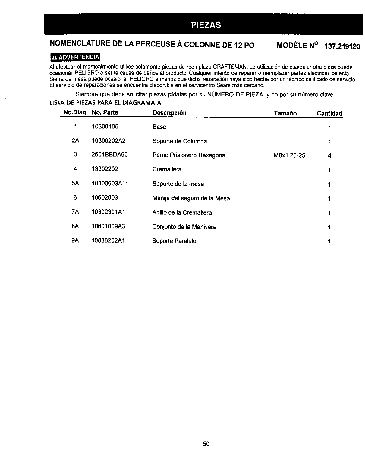
NOMENCLATURE DE LA PERCEUSE A COLONNE DE 12 PO MODELE N° 137.219120
AIefectuar el mantenimiento utilice solamente piezas de reemplazo CRAFTSMAN.La utilizaci6nde cualquierotra piezapuede
ocasionar PELIGRO o ser la causa de daSos al producto.Cualquier intento de reparar o reemplazar panes electric,as de esta
Sierra de mesa puede ocasionar PELIGRO a menos que dicha reparaci6nhaya sido hecha por untecnico calificadode servicio.
El servicio de reparaciones se encuentra disponibleen el servicentro Sears mas cercano.
Siempre que deba solicitar piezas pidalas por su NOMERO DE PIEZA, y no por su nl3mere clave.
USTA DE PIEZAS PARA ELDIAGRAMA A
No.Diag: No. Parte Descripcibn Tamafio Cantidad
1 10300105 Base 1
2A 10300202A2 Soporte de Columna 1
3 2601BBDA90 Perno Prisionero Hexagonal M8x1.25-25 4
4 13902202 Cremallera 1
5A 10300603A11 Soporte de la mesa 1
6 10602003 Manija del seguro de la Mesa 1
7A 10302301A1 Anillo de la Cremallera 1
8A 10601009A3 Conjunto de la Manivela 1
9A 10838202A1 Soporte Paralelo 1
50
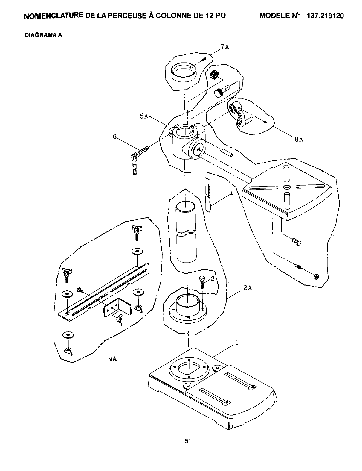
NOMENCLATURE DE LA PERCEUSE A COLONNE DE 12 PO MODELE Nu 137.219120
DIAGRAMA A
7A
8A
/
t
I
51
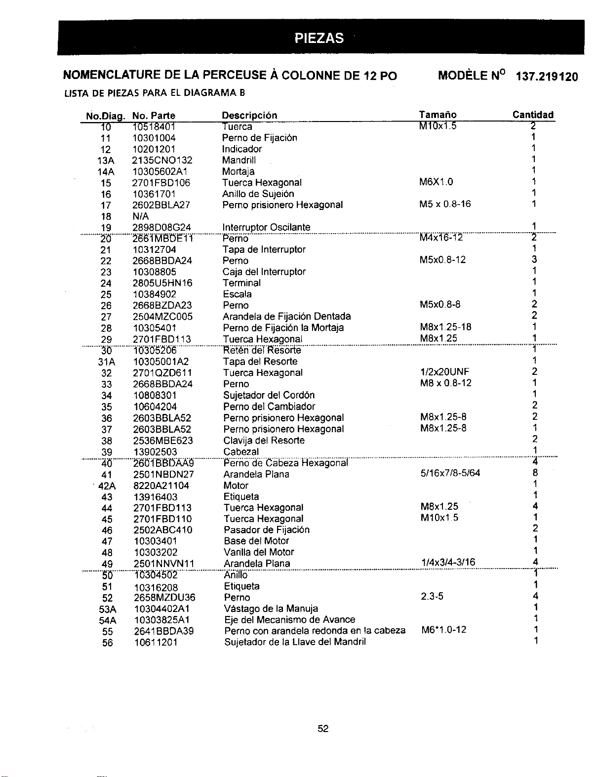
NOMENCLATURE DE LA PERCEUSE A COLONNE DE 12 PO
LISTA DE PIEZAS PARA ELDIAGRAMA B
MODELE No 137.219120
No,Diag. No. Parte Descripcion Tamaho Cantidad
10 10518401 Tuerca M10xl 5 2
11 10301004 Perno de Fijaci6n 1
12 10201201 Indicador 1
13A 2135CNO132 Mandrill 1
14A 10305602A1 Mortaja 1
15 2701FBD106 Tuerca Hexagonal M6Xl.0 1
16 10361701 Anillo de Sujei6n 1
17 2602BBLA27 Perno prisionero Hexagonal M5 x 0.8-16 1
18 N/A
19 2898D08G24 Interruptor Oscilante 1
..........._i_...........__1____ ................P_i:_5...........................................................................................I_i_:__ ....................................:_...........
21 10312704 Tapa de Interruptor 1
22 2668BBDA24 Pemo M5x0.8-12 3
23 10308805 Caja del Interruptor 1
24 2805U5HN16 Terminal 1
25 10384902 Escala 1
26 2668BZDA23 Perno M5x0.8-8 2
27 2504MZC005 Arandela de Fijaci6n Dentada 2
28 10305401 Perno de Fijaci6n la Mortaja M8x1.25-18 1
29 2701FBD113 Tuerca Hexagonal M8xl.25 1
.........._i_..........._'_3"0'5:_i_........................._'ff'a'_'f'l_'_5_ ..........................................................................................................................._...........
31A 10305001A2 Tapa del Resorte 1
32 2701QZD611 Tuerca Hexagonal I/2x20UNF 2
33 2668BBDA24 Perno M8 x 0.8-12 1
34 10808301 Sujetador del Cord6n 1
35 10604204 Perno del Cambiador 2
36 2603BBLA52 Perno prisionero Hexagonal M8x1.25-8 2
37 2603BBLA52 Perno prisionero Hexagonal M8x1.25-8 1
38 2536MBE623 Clavija del Resorte 2
39 13902503 Cabezal 1
..........:4i_...........26b_IBBI3_ ................P_i"55"a'__'_5"e_aFl_ _h'_'l.................................................................................................'_...........
Arandela Plana 5/16x7/8-5/64 8
41 2501NBDN27
" 42A 8220A21104 Motor 1
43 13916403 Etiqueta 1
44 2701FBD113 Tuerca Hexagonal M8x125 4
45 2701FBD110 Tuerca Hexagonal M10x1.5 1
46 2502ABC410 Pasador de Fijaci6n 2
47 10303401 Base del Motor 1
48 10303202 Varilla del Motor 1
49 2501NNVN11 Arandela Plana 114x314-3116 4
...........S_...........i_30_'50;_........................XSIII_........................................................................................................................................................_1...........
51 10316208
52 2658MZDU36
53A 10304402A1
54A 10303825A1
55 2641BBDA39
56 1O6112O1
Etiqueta
Perno 2.3-5
V_stago de la Manuja
Eje del Mecanismo de Avance
Perno con arandela redonda en la cabeza M6"1.0-12
Sujetador de la Llave de] Mandril
1
4
1
1
1
1
52
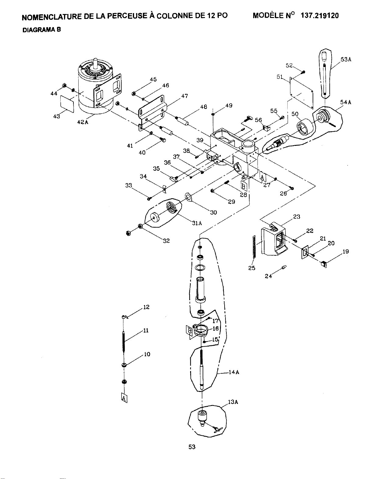
NOMENCLATURE DE LA PERCEUSE A COLONNE DE 12 PO
DIAGRAMA B
MODI_LE N° 137.219120
53A
44
45
46
47
48
56
5O
54A
33
jlO
4O
36
35
34
39
25
I
I
2J
22
21
13A
53
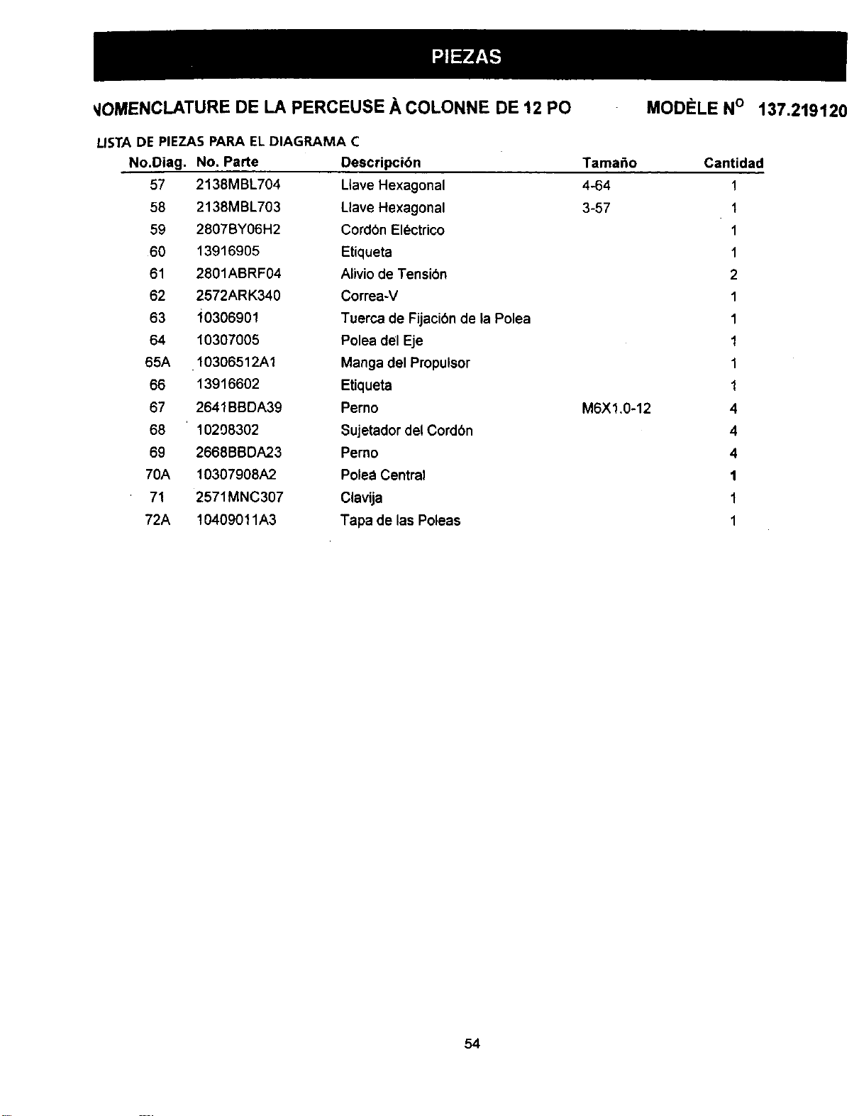
_IOMENCLATURE DE LA PERCEUSE .&.COLONNE DE 12 PO MODELE N° 137.219120
LISTA DE PIEZAS PARA ELDIAGRAMA C
No.Diag. No. Parte Descripcibn
57
58
59
60
61
62
63
64
65A
66
67
68
69
70A
71
72A
2138MBL704
2138MBL703
2807BY06H2
13916905
2801ABRF04
2572ARK340
10306901
10307005
10306512A1
13916602
2641BBDA39
10208302
2668BBDA23
10307908A2
2571MNC307
10409011A3
Ltave Hexagonal
Llave Hexagonal
Cordbn El_ctrico
Etiqueta
Alivio de Tensi6n
Correa-V
Tuerca de Fijaci6n de la Polea
Polea del Eje
Manga del Propulsor
Etiqueta
Perno
Sujetador del Cord6n
Pemo
Polea Central
Clavija
Tapa de las Poleas
Tama_o
4_4
3-57
M6X1.0-12
Cantidad
1
1
1
1
2
1
1
1
1
1
4
4
4
1
1
1
64
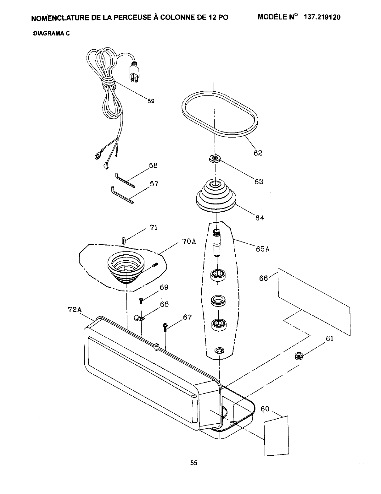
NOMENCLATURE DE LA PERCEUSE A COLONNE DE 12 PO
DIAGRAMA C
MODI_LE N° 137.219120
59
57
62
63
72A
68
70A
/
64
65A
55

............ For repair of major brand appliances in your own home...
no matter who made it, no matter who sold it[ i;_i_
!ili HOME ......
:__, 1-800-4-MY- SMA._ime.aayorn_.t ,,.::,....
ii_:i:
(1-800469-4663)
::::::
.....i:!?::
: : ;::2;
_ www.sears.com ii_iiiii_ii
_' To bring in products such as vacuums, awn equipment and electronics i;_
;ii;:iiii_for repa=r, call for the Iocat=on of your nearest Sears Parts & Repa,r Center. _
1-800-488-1222 _=e, d_yo_._.t
www.sears.com
For the replacement parts,accessories and owner's manuals
that you need to do-it-yourself,call Sears PartsDirect _ !
1-800-366-PART 6am-..m CST
(1-800-366-7278) 7 day_ a week
www.sears.condpartsdirect
To purchase or inquire about a Sears Service Agreement:
1 800 827 6655 _i_'_
7 a.m. - 5 p.m. CST, Mon, - Sat. ::i_iii
Para pedir se_icio de reparacidn a domicilio, Au.Canada pour service en franqais: ;_
y para ordenar piezas con enttega a domicilio: 1.877.LE.FOYER =,' _
1-888-SU-HOGAR =" (1-877-533-6937) i_
i_ (1-888-784-6427) _!
.............r 1
0,,.,.,-_=._ _o L HomeCentral" _ Registered Tradetnatk/_ Tradernad( o, Sea.,Roebuck an. Co
® Marca Registrada,n_Marc_de F#_bric_deSears,Roebuck 8ridCo.
FULL ONEYEAR WARRANTY
If _ prOdUCtfaiis due to a defect _1m=tar_alor wod<mlnship w_6_iflone year from the date of purchase. Sears ,
reppit it free of charge.
Contact a Sears Ser,,_ce Cenfer for,'ep_r,
If this product is used for commercial or rental purposes, thi= warr11_ltyapplieSonly for 90 days from the date of
purchase.
This warranty g._es you spp{dfi¢legal tights, _ you _ also have other rights whichvaW from alale to stale.
Seats, Roebuck and Co., Dept. 817 WA, Hoffman Estates, IL 6017_
• _ M_ w_mtL_edafocto_demal_islobtxicadd_dentin_ p_m_r=rioapat#tdetsfectta#ecom_-a.
S_mis nCatar_t=inco=oIlguno.
CoNactst'J__ unC_tm deS_m#dodeSe=r=pra fotel_u-add_
Sl_ _ = u=apatatin= €om_dak=o i_=-a_¢Ulet,_,=tagatanM=ema:a_o p_r_o=i:_men__ a_
deisfKhade€=rnl_'_.
Esu|_aran#afoolm_adam,':'_ is_desespressosyuun_k_poc_,lausts<l®ra,-oitos_x_ quevadan_ m
Sears,Roebuckand Co., Dept.alTW_ HoffrnanE=tata=,IL60179
11/2000