Loading ...
Loading ...
Loading ...
Page 23 of 53
2)
After the unit is installed and the gas line hooked up, crimp a fork connector to each wire and
attach them to the TH/TP and TH screws located on the valve.
Après que l'unité est installée et la conduite de gaz accroché, sertir un connecteur fourchette pour
chaque fil et les joindre à la vis TH / TP et TH situé sur la valve.
3) Check tests can be performed on the valve by using the trouble-shooting guide, Section 5.0.
Vérifiez les tests peuvent être effectués sur la valve en utilisant le guide de dépannage, la
section 5.0.
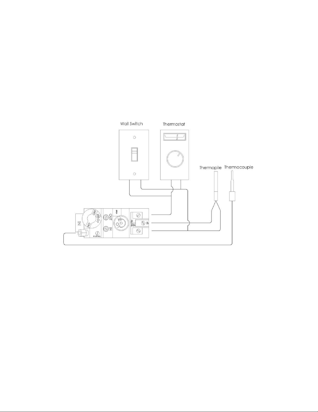
4) This switch may be connected in parallel with a thermostat, digital on/off remote or wall switch (see Figure
4).
Ce commutateur peut être connecté en parallèle avec un thermostat numérique, télécommande
marche / arrêt ou un interrupteur mural (voir Figure 4).
Figure 4
3.3.5 DIRECT VENT INFORMATION / DIRECT VENT D'INFORMATION
The unit must be connected to listed 2-ply aluminium venting, 3” flex vent on the exhaust side and listed 6” flex
vent on the air intake side. Install the vent components according to the manufacturer's instructions being sure
to use spacers (see Figure 5) every 2’ to ensure correct spacing is maintained between air intake and exhaust.
Slope horizontal pipe at least 1/4" (6 mm) rise per foot of horizontal run away from the fireplace. Allow 1" (25
mm) clearance to the vent. Refer to the graph for allowable vent configurations. Be sure to ensure that
termination area allows enough room for adequate combustion and ventilation air and that the flow of combustion
and ventilation air is not obstructed.
L'appareil doit être connecté à cotée 2 couches d'aluminium ventilation , 3 "flex évent sur le côté de
l'échappement et répertoriés 6 " flex évent sur le côté d'admission d'air . Installez les composants de ventilation
selon les instructions du fabricant en veillant à utiliser des entretoises ( voir figure 5) tous les 2’ pour assurer un
espacement correct est maintenu entre l'apport d'air et l'échappement. Pente tuyau horizontal d'au moins 1/4 "
( 6 mm ) par pied de course horizontale loin du foyer . Laisser 1 " ( 25 mm) à l'évent . Reportez-vous au
graphique de configuration de l'évacuation admissibles . Veillez à ce que la zone de terminaison permet assez
de place pour combustion et l'air de ventilation et que le débit de combustion et de l'air de ventilation n'est pas
obstruée.
Loading ...
Loading ...
Loading ...