Loading ...
Loading ...
Loading ...
5
REV 2 - 1401030955
L-C2-356
23 3/4"
12"
12 3/8"
2"
2"
1"
X
HEIGHT
4"
WIDTH
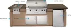
GAS SUPPLY PLUMBING REQUIREMENTS:
The gas supply pipe connection is to be made
through the fl oor at the rear of the enclosure.
Install the gas line stub at least 2" away from the
side walls and 1" from the back wall, but within 5"
of the back wall, as illustrated by the shaded area
X in Fig. 5-1.
CAUTION: An external valve (with a removable
key) in the gas line is advised for
safety and convenience, particularly
if the unit is accessible to children.
GAS SUPPLY AND MANIFOLD PRESSURES:
For natural gas - normal 7" water column (w.c.),
minimum 3-1/2", maximum 10-1/2". For propane
gas - normal 11" w.c., minimum 8", maximum 13".
PREPARING FOR INSTALLATION (Cont.)
INSTALLATION
A REGULATOR MUST BE PROVIDED AT THE
BOTTLE OR GAS SOURCE FOR USE WITH
PROPANE GAS.
Fig. 5-1
8 1/2"
Height
22 3/4"
11 1/2"
Width*
1. CHECKING FUEL AND PROPER ORIFICES
AOG units are equipped with orifi ces for natural
gas, unless otherwise indicated. For use with
propane gas, smaller orifi ces must be installed
to avoid hazardous overheating. Please refer
to Table 1 for the correct orifi ce size. Check
the orifi ce size by following the instructions
below. The drill size is stamped on the orifi ce.
If the number is not visible you may have to
remove the orifi ce (as detailed below) to read
the number stamped on the side of the orifi ce.
IF YOU ARE NOT SURE YOU HAVE THE
CORRECT SIDEBURNER ORIFICE SIZE (OR
WISH TO CHANGE THE ORIFICE), FOLLOW THE
STEPS BELOW.
CAUTION: If the burner has been in use, wait
until the burner and its components
are cool to the touch.
a. Remove sideburner cover and lift off cooking
grid.
b. Remove the control knobs and the screws
found on each side of the control panel. Then
carefully lift away the control panel.
Note: Carefully, lift the control panel away from
the frame. The spark generator for the
ignition system is attached to the inside
of the control panel. The spark generator
knob need not be detached, but the wires
must be unplugged from the generator
before the face is completely removed.
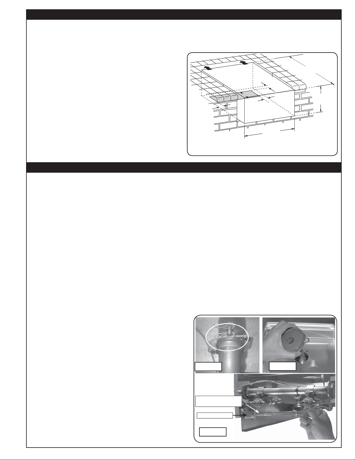
c. Reach up under the burner support and
remove the burner retaining clip (see Fig.
5-1), located at the rear of the burner pipe.
d. Remove the burner cap and carefully lift
the burner up and out, clearing the ceramic
electrode (see Fig. 5-2), and pulling the
burner tube away from the orifi ce, located
on the end of the orifi ce holder on the left
side of the unit (see Fig. 5-3).
Note: You do not have to lift the burner
completely out of the unit to access the
orifi ce.
e. Using a
3
/
8
" socket, remove orifi ce from the
orifi ce holder (see Fig. 5-3) and check the
number stamped on the orifi ce face.
Fig. 5-2
Fig. 5-1
Fig. 5-3
Orifi ce located at
end of orifi ce holder
Orifi ce holder
*
12" width when installed in combustible framing
Loading ...
Loading ...
Loading ...