CAUTION:
Weight on this product should not exceed 250 lbs.
Product May Vary Slightly From Pictured.
Exercise can present a
health risk. Consult a
physician before beginning
any exercise program with
this equipment. If you feel
faint or dizzy, immediately
discontinue use of this
equipment. Serious bodily
injury can occur if this
equipment is not assembled
and used correctly. Serious
bodily injury can also occur
if all instructions are not
followed. Keep others and
pets away from equipment
when in use. Always make
sure all bolts and nuts are
securely tightened prior to
each use. Follow all safety
instructions in this manual.
!
WARNING
STAMINA PRODUCTS
MADE IN CHINA
© 2020 Stamina Products, Inc.
2020, 09
When calling for parts or
service, please specify
the following numbers
:
Model#: 15-4845
S/N: _____________
This Product is Distributed Exclusively by
2040 N Alliance Ave, Springfi eld, MO 65803
Customer Care
1 (800) 375-7520
www.staminaproducts.com
Owner's
Manual


TABLE OF CONTENTS
SAFETY INSTRUCTIONS
3
1. Save these instructions and ensure that other exercisers read this manual prior to using the
Stamina®
Magnetic Recumbent Exercise Bike 845
for the fi rst time.
2. Read all warnings and cautions posted on the
Stamina® Magnetic Recumbent Exercise Bike 845.
3. The
Stamina® Magnetic Recumbent Exercise Bike 845
should only be used after a thorough review of the
Owner’s Manual. Make sure that it is properly assembled and tightened before use.
4. We recommend that two people be available for assembly of this product.
5. Keep children away from the
Stamina® Magnetic Recumbent Exercise Bike 845.
Do not allow children to
use or play on the
Stamina® Magnetic Recumbent Exercise Bike 845.
Keep children and pets away from
the
Stamina® Magnetic Recumbent Exercise Bike 845
when it is in use.
6. The
Stamina® Magnetic Recumbent Exercise Bike 845
is not a freewheeling exercise bike; therefore,
pedal speed should be reduced in a controlled manner to prevent injury from spinning pedals.
7. It is recommended that you place this exercise equipment on an equipment mat.
8. Set up and operate the
Stamina® Magnetic Recumbent Exercise Bike 845
on a solid level surface. Do not
position the
Stamina® Magnetic Recumbent Exercise Bike 845
on loose rugs or uneven surfaces.
9. Make sure that adequate space is available for access to and around the
Stamina® Magnetic Recumbent
Exercise Bike 845.
10. Adjust the Leveling Caps(84) on the Rear Stabilizer(13) so that the bike sits on the fl oor without rocking.
11. Before using, inspect the
Stamina® Magnetic Recumbent Exercise Bike 845
for worn or loose
components, and securely tighten or replace any worn or loose components prior to use.
12. Before using, always check the Seat Slider(15) to be sure it is secure, and securely tightened with the
Lever(17).
13. Each user should adjust the seat per instructions on page 14.
14. Consult a physician prior to commencing an exercise program and follow his/her recommendations in
developing your fi tness program. If at any time during exercise you feel faint, dizzy, or experience pain, stop
and consult your physician.
15. Always choose the workout which best fi ts your physical strength and fl exibility level. Know your limits and
train within them. Always use common sense when exercising.
16. Do not wear loose or dangling clothing while using the
Stamina® Magnetic Recumbent Exercise Bike 845.
17. Never exercise in bare feet or socks; always wear proper footwear such as running, walking, or cross training
shoes that fi t well, provide foot support, and feature non-skid rubber soles.
18. Be careful to maintain your balance while using, mounting, dismounting, or assembling the
Stamina®
Magnetic Recumbent Exercise Bike 845,
loss of balance may result in a fall and serious bodily injury.
19. The
Stamina® Magnetic Recumbent Exercise Bike 845
should not be used by persons weighing over 250
pounds.
20. The
Stamina® Magnetic Recumbent Exercise Bike 845
should be used by only one person at a time.
21. The
Stamina® Magnetic Recumbent Exercise Bike 845
is for consumer use only. It is not for use in public
or semipublic facilities.
!
WARNING
Cancer and Reproductive Harm www.P65Warnings.ca.gov
Consult your physician before starting this or any exercise program. This is
especially important if you are over the age of 35, have never exercised before,
are pregnant, or suff er from any health problem. This product is for home use
only. Do not use in institutional or commercial applications. Failure to follow all
warnings and instructions could result in serious injury or death.
To reduce the risk of serious injury, read the following Safety Instructions
before using the Stamina® Magnetic Recumbent Exercise Bike 845.
!
WARNING
!
WARNING
Safety Instructions ............................................. 3
Before You Begin ............................................... 5
Equipment Warning, Caution & Notice Labels
.......... 6
Hardware Identifi cation Chart ........................... 7
Assembly Instructions ....................................... 8
Set Up Instructions .......................................... 13
Operational Instructions .................................. 14
Computer Instructions ..................................... 15
Storage .............................................................. 25
Maintenance ...................................................... 25
Conditioning Guidelines .................................. 26
Warm-Up and Cool-Down ................................ 27
Product Parts Drawing .................................... 28
Parts List ........................................................... 29
Warranty ............................................................ 32
Notes ................................................................. 33
Fax/Mail Ordering Form ................................... 34

NEED HELP?
CONTACT US FIRST
1 (800) 375-7520
customer.care@staminaproducts.com
Hi! From all of us here at Stamina Products, thank you for your purchase. We
know that you have big fitness goals in mind and we are here to help you along.
Call us, email us, or send us a message on Facebook. Be sure to contact us if you
have any questions on your new product. We look forward to hearing from you!
With your body in mind,
Stamina Customer Care
To enact your extended warranty and to help us better
serve you, please go online and register your new product.
register.staminaproducts.com
ONLINE
customer.care@staminaproducts.com
www.staminaproducts.com
TELEPHONE
1 (800) 375-7520
FAX
(417) 889-8064
MAIL
Stamina Products, Inc.
ATTN: Customer Care
2040 N Alliance Ave
Springfield, MO 65803
facebook.com/StaminaProducts
facebook.com/AeroPilates
CUSTOMER CARE HOURS:
Monday-Thursday, 7:30 AM-5:00 PM, Central Time
Friday, 8:00 AM-3:00 PM, Central Time
It is quick and easy to register online, but if you’re a little old school or just need a
reason to raise that little flag on your mailbox, fill out the info on the last page of this
manual and mail it in.
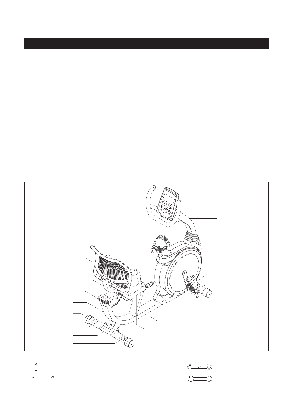
Seat
Rear Stabilizer
Main Frame
Wheel Cap
Computer
Right Cover
Seat Back
Leveling Cap
Seat Frame
Handrail
Right Pedal
Upright Cover
Back Rail Cover
BEFORE YOU BEGIN
5
Right Pedal Strap
Upright
Front Stabilizer
Caution Label
Serial Decal
Pulse Sensor Plate
Thank you for choosing the
Stamina® Magnetic
Recumbent Exercise Bike 845.
We take great
pride in this quality product and hope it will provide
many hours of quality exercise to make you feel
better, look better, and enjoy life to its fullest.
It's a proven fact that a regular exercise
program can improve your physical and mental
health. Too often, our busy lifestyles limit our
time and opportunity to exercise. The
Stamina®
Magnetic Recumbent Exercise Bike 845
provides a convenient and simple method to begin
your journey of getting your body in shape and
achieving a happier and healthier lifestyle.
Before reading further, please review the
drawing below and familiarize yourself with the
parts that are labeled. Locate the serial decal on
the product and write the serial number on the
cover of the manual in the space provided. See
page 6 for an image of the serial decal. Model
number and serial number are required when
calling for assistance.
Read this manual carefully before using the
Stamina® Magnetic Recumbent Exercise Bike
845.
Providing you with a quality product is Stamina's
top priority. However, sometimes there could be a
missing or incorrectly sized part. If you have any
questions or problems with the parts included with
your
Stamina® Magnetic Recumbent Exercise
Bike 845,
please do not return the product.
Contact us FIRST!
If a part is missing or defective, please contact
Customer Care for assistance. Call us toll free
at 1-800-375-7520 (in the U.S.) or live chat on
staminaproducts.com. Our Customer Care Staff is
available to assist you from 7:30 A.M. to 5:00 P.M.
(Central Time) Monday through Thursday and 8:00
A.M. to 3:00 P.M. (Central Time) on Friday.
Be sure to have the name and model number of
the product available when you contact us.
Handlebar
THE FOLLOWING TOOLS ARE INCLUDED FOR ASSEMBLY :
Allen Wrench (4mm)
Allen Wrench w/ Screwdriver (6mm)
Wrench
Opening Wrench
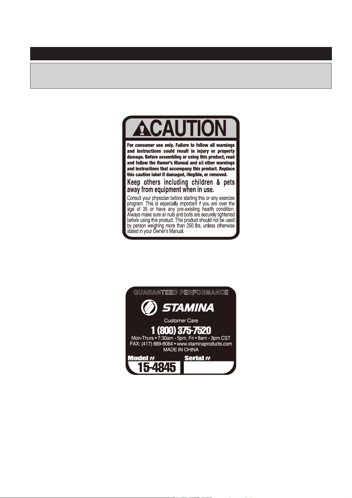
This chart is provided to help identify the warning, caution, and notice labels on the
Stamina®
Magnetic Recumbent Exercise Bike 845.
Please take a moment to familiarize yourself with all of
the warning, caution, and notice labels.
EQUIPMENT WARNING, CAUTION & NOTICE LABELS
6
CAUTION LABEL(114)
To best serve you, our Customer Care Representatives will
need your serial number. For quick access, write in your
serial number on the cover of the manual.
SERIAL DECAL(115)
7
length
length
mm.
in.
INCHES
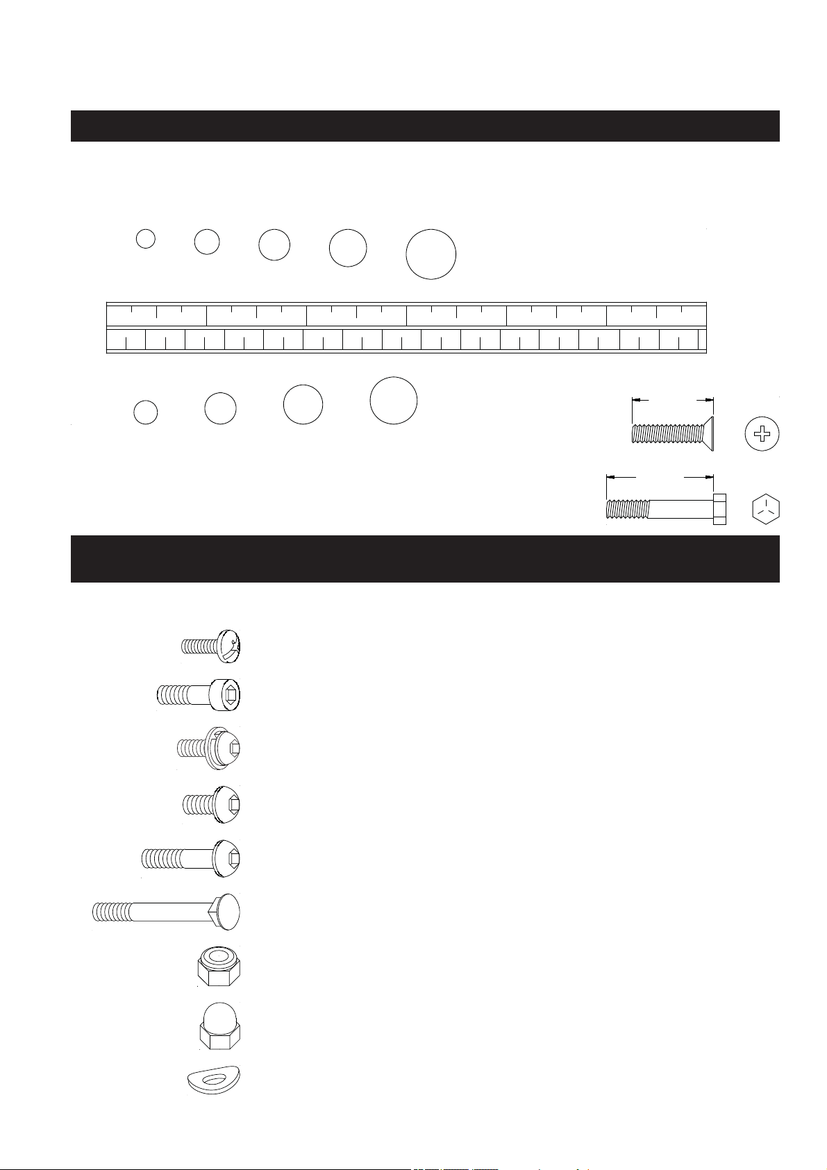
This chart is provided to help identify the fasteners used in the assembly process. Place the washers or
the ends of the bolts or screws on the circles to check for the correct diameter. Use the small scale to
check the length of the bolts and screws.
NOTICE:
The length of all bolts and screws, except those with flat
heads, is measured from below the head to the end of the bolt
or screw. Flat head bolts and screws are measured from the
top of the head to the end of the bolt or screw.
After unpacking the unit, open the hardware bag and make sure that you have all the following
fasteners. Some fasteners may be already attached to the parts.
MILLIMETERS
0 10 20 30 40 50 60 70 80 90
100
110
120
130 140
150
0 1/2
1 1/2
2 1/2
3 1/2
4 1/2
5 1/2
6
6 8
10
12
3/16"
1/4"
5/16" 3/8" 1/2"
HARDWARE IDENTIFICATION CHART
Part No. and Description Qty
25 Carriage Bolt (M8 x 1.25 x 66mm) 2
78 Acorn Nut (M10 x 1.5) 4
22 Bolt, Button Head (M6 x 1 x 13mm) 7
79 Arc Washer (M10) 4
4 Screw, Round Head (M5 x 0.8 x 10mm) 4
26 Nylock Nut (M8 x 1.25) 2
7 Bolt, Button Head w/ Washers (M8x1.25x16mm) 4
5 Bolt, Socket Head (M8 x 1.25 x 25mm) 2
23 Bolt, Button Head (M6 x 1 x 45mm) 4
102 Bolt, Button Head (M8 x 1.25 x 36.5mm) 2
ASSEMBLY INSTRUCTIONS
8
Place all parts from the box in a cleared area and position them on the fl oor in front of you. Remove
all packing materials from your area and place them back into the box. Do not dispose of the packing
materials until assembly is completed. Read each step carefully before beginning. If you are missing
a part, please go to staminaproducts.com under the Customer Care section and order the part
(in the U.S.). Our Customer Care Staff is available to assist you from 7:30 A.M. to 5:00 P.M. (Central
Time) Monday through Thursday and 8:00 A.M. to 3:00 P.M. (Central Time) on Friday.
Some product parts are fi t tested at the factory to ensure proper fi t and alignment. Marks in
the paint may be noticeable, but are not an indication of damage.
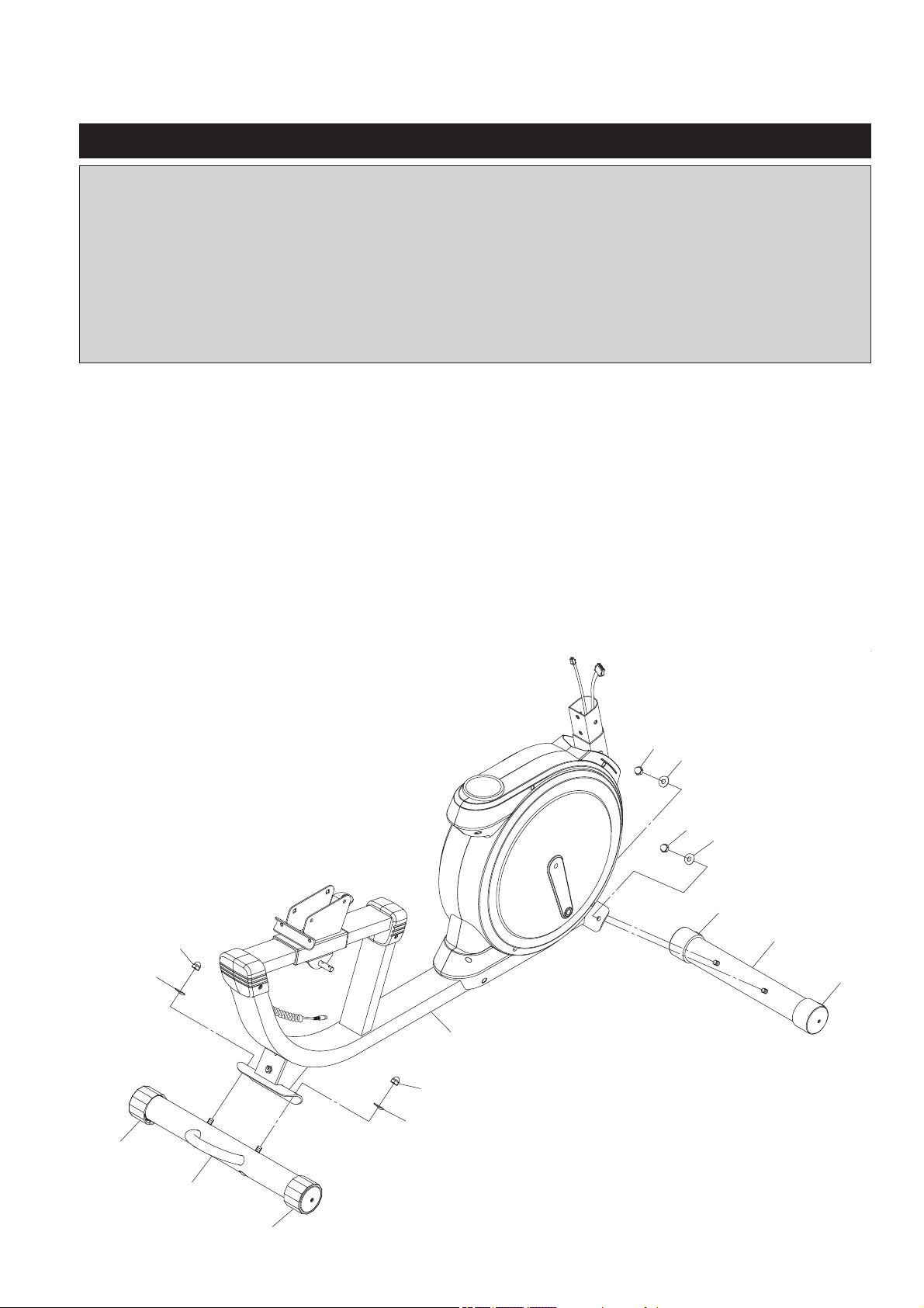
84
84
13
11
10
77
77
79
78
79
78
79
78
79
78
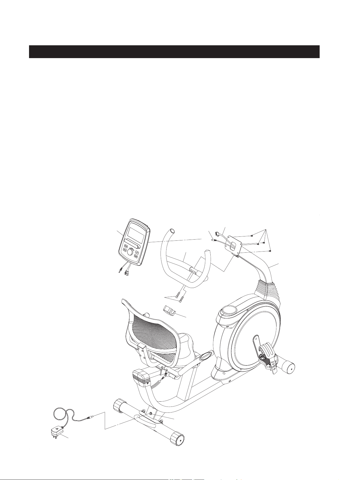
STEP 1
Position the Wheels in the WHEEL CAPS(77) on the FRONT STABILIZER(11) facing the front. Attach
the FRONT STABILIZER(11) to the front of the MAIN FRAME(10) with ARC WASHERS(M10)(79) and
ACORN NUTS(M10x1.5)(78).
STEP 2
Attach the REAR STABILIZER(13) to the MAIN FRAME(10) with ARC WASHERS(M10)(79) and ACORN
NUTS(M10x1.5)(78).
NOTE: You can adjust the LEVELING CAPS(84) on the REAR STABILIZER(13) to keep the recumbent
bike stable.
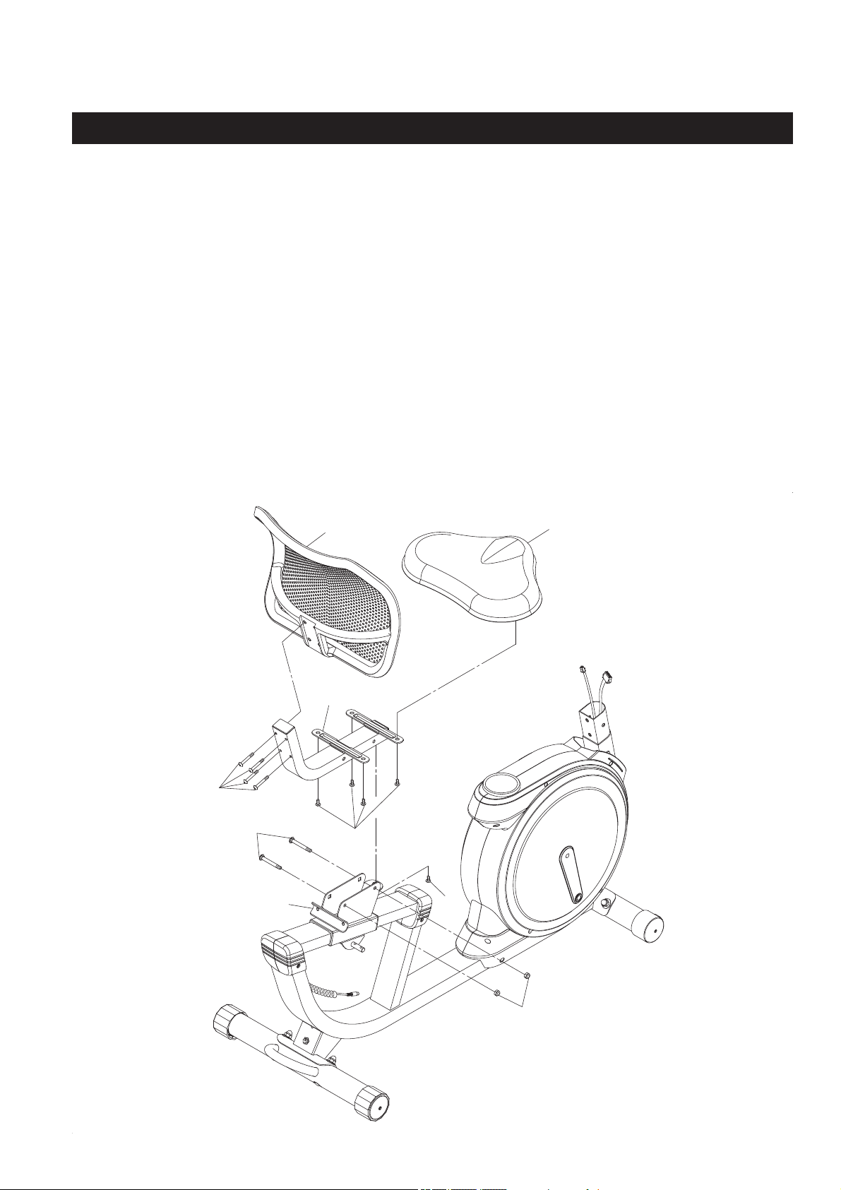
ASSEMBLY INSTRUCTIONS
STEP 3
Attach the
SEAT FRAME(16)
to the
SEAT SLIDER(15)
with
CARRIAGE BOLTS(M8x1.25x66mm)(25)
and
NYLOCK NUTS(M8x1.25)(26),
and bolt
BUTTON HEAD BOLT(M6x1x13mm)(22)
from the bottom
of the
SEAT SLIDER(15).
STEP 4
Attach the
SEAT(19)
to the
SEAT FRAME(16)
with
BUTTON HEAD BOLTS(M6x1x13mm)(22).
Attach
the
SEAT BACK(20)
to the
SEAT FRAME(16)
with
BUTTON HEAD BOLTS(M6x1x45mm)(23).
9
23
25
22
22
26
15
16
20
19
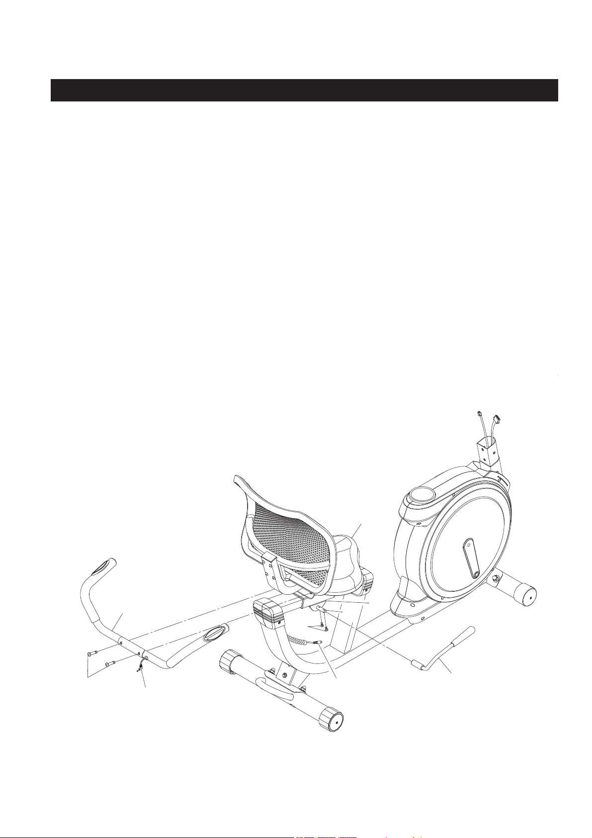
ASSEMBLY INSTRUCTIONS
STEP 5
Slide the
LEVER(17)
onto the
LEVER CONNECTOR(30)
located under the
SEAT(19)
and secure with
BUTTON HEAD BOLTS(M6x1x13mm)(22).
STEP 6
Attach the
HANDRAIL(18)
to the
SEAT SLIDER(15)
with
BUTTON HEAD BOLTS(M8x1.25x36.5mm)
(102).
Plug the
PULSE SENSOR WIRE(107)
into the
PULSE SENSOR EXTENSION WIRE(100).
10
17
18
102
107
100
22
30
15
19
92
91
100
105
10
7
7
7
2
83
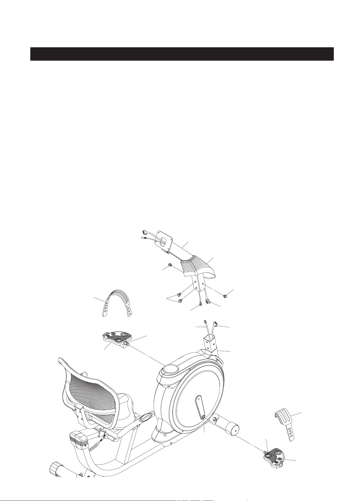
ASSEMBLY INSTRUCTIONS
11
Shoulder
Shoulder
STEP 7
NOTE: The RIGHT PEDAL(112) has an R stamped on the end of the pedal shaft. The RIGHT PEDAL
(112) has right hand threads and is tightened by turning clockwise. The LEFT PEDAL(91) has
an L stamped on the end of the pedal shaft. The LEFT PEDAL(91) has left hand threads and is
tightened by turning counterclockwise.
Thread the RIGHT PEDAL(112) into the RIGHT CRANK(109) as shown. Tighten the pedal securely. The
shoulder of the PEDALS(91, 112) should be in contact with the CRANKS(14, 109) when securely tightened.
Select the RIGHT PEDAL STRAP(113) which has R marked on it. Snap the three hole end to the inside
edge of the RIGHT PEDAL(112). Insert the other end of the strap through the slot and snap the strap to
the hook on the outside edge of the RIGHT PEDAL(112). Select adjustment holes which allow your foot to
be easily removed from the pedals. Use the same procedure to attach the LEFT PEDAL(91) to the LEFT
CRANK(14) and to attach the LEFT PEDAL STRAP(92) to the LEFT PEDAL(91).
STEP 8
Slide the UPRIGHT COVER(83) on the UPRIGHT(2) as shown in the illustration below. Connect the
EXTENSION CONTROL CABLE(75) to the CONTROL CABLE(105). Connect the PULSE SENSOR
CONNECTION WIRE(101) to the PULSE SENSOR EXTENSION WIRE(100). Insert the UPRIGHT(2) onto
the MAIN FRAME(10) and secure with BUTTON HEAD BOLTS w/ WASHERS(M8x1.25x16mm)(7). Slide
the UPRIGHT COVER(83) down to cover the bolts.
ASSEMBLY INSTRUCTIONS
12
106
104
2
4
1
3
5
6
75
101
STEP 9
Attach the HANDLEBAR(3) to the UPRIGHT(2) with SOCKET HEAD BOLTS(M8x1.25x25)(5). Clip the
HANDLEBAR COVER(6) onto the HANDLEBAR(3) to cover the SOCKET HEAD BOLTS(M8x1.25x25)(5).
STEP 10
Plug the EXTENSION CONTROL CABLE(75) and PULSE SENSOR CONNECTION WIRE(101) into the
connecting wires of the COMPUTER(1), and push the excess wires back into the UPRIGHT(2). Attach the
COMPUTER(1) to the plate on the UPRIGHT(2) with ROUND HEAD SCREWS(M5x0.8x10mm)(4).
NOTE: Be careful not to damage the wires when attaching the COMPUTER(1).
STEP 11
Plug the ADAPTER(104) into the SOCKET of the POWER WIRE(106) located on the back of the recumbent
bike. Plug the ADAPTER(104) into an electrical outlet.
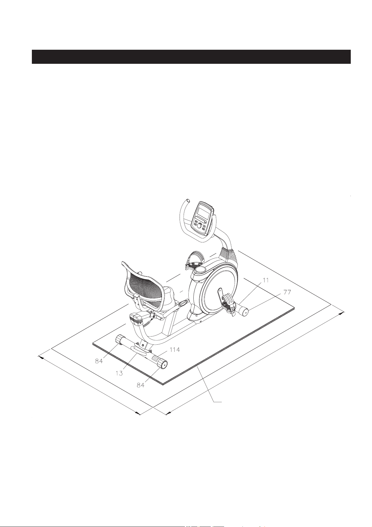
Place the
Stamina® Magnetic Recumbent Exercise Bike 845
in the area where it will be used. It is
recommended that the
Stamina® Magnetic Recumbent Exercise Bike 845
be placed on an equipment
mat. The
Stamina® Magnetic Recumbent Exercise Bike 845
is approximately 51.1 inches long (max.)
x 23.6 inches wide x 46.3 inches tall. (These dimensions may vary up to one inch.) An area 4 feet wide
x 7 feet long is required for safe operation of the
Stamina® Magnetic Recumbent Exercise Bike 845.
Make sure that adequate space is available for access to and passage around the
Stamina® Magnetic
Recumbent Exercise Bike 845.
LEVELING:
Adjust the
LEVELING CAPS(84)
on the
REAR STABILIZER(13)
so that the
Stamina®
Magnetic Recumbent Exercise Bike 845
sits on the fl oor without rocking.
MOVING:
The
Stamina® Magnetic Recumbent Exercise Bike 845
has a pair of Wheels in the
WHEEL CAPS(77)
on the
FRONT STABILIZER(11).
Lift up the
REAR STABILIZER(13)
to
move the
Stamina® Magnetic Recumbent Exercise Bike 845.
FUNCTION INSPECTION:
Visually inspect the
Stamina® Magnetic Recumbent Exercise Bike 845
to verify that assembly is as
shown in the above illustration. Check the function of the
Stamina® Magnetic Recumbent Exercise
Bike 845
by turning the crank slowly through one complete revolution to verify that the drive train
functions properly.
CAUTION:
Locate and read the
CAUTION LABEL(114)
on the
Stamina® Magnetic Recumbent
Exercise Bike 845.
Make sure that all users read the
CAUTION LABEL(114)
before using
the product.
SET UP INSTRUCTIONS
13
4 feet
7 feet
Equipment Mat
(not included)
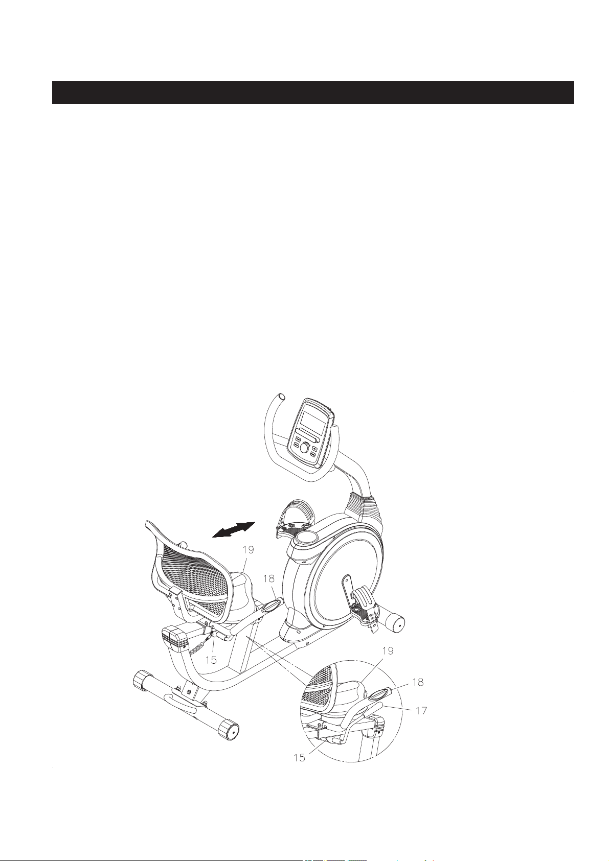
SEAT ADJUSTMENT
1. Refer to the detail view below. Push down the
LEVER(17)
to unlock the
SEAT SLIDER(15)
until the
SEAT(19)
can be moved. Slide the
SEAT(19)
to the desired position. Lock the
SEAT SLIDER(15)
in
position by pulling the
LEVER(17)
upward to lock the
SEAT SLIDER(15)
securely.
2. Sit on the seat and place your feet on the pedals. You should be able to move through a complete
pedal stroke without locking your knees or shifting your hips on the seat. The seat is too close to the
pedals if you have more than a slight bend in your knees at the bottom of the pedal stroke. The seat
is too far from the pedals if you have to completely straighten your knees at the bottom of the pedal
stroke.
CAUTION:
Always pull the
LEVER(17)
upward to securely tighten the
SEAT SLIDER(15)
after adjusting
the
SEAT(19)
to a new position.
Proper seat adjustment is important. There is a rail on the
MAIN FRAME(10)
for sliding the
SEAT
SLIDER(15)
to allow users to adjust the position of the
SEAT(19)
for effi cient exercise.
OPERATIONAL INSTRUCTIONS
14
CAUTION:
Do not use the HANDRAIL
(18) to raise or lower your
full body weight.
15
MODE:
UP/DOWN
DIAL:
RESET
:
START/STOP:
RECOVERY :
BODY FAT
:
Your Stamina® Magnetic Recumbent Exercise Bike 845 utilizes a magnetic braking system to create
resistance for your workout. You control the amount and pattern of this resistance by means of the advanced
computer console mounted at the center of the Handlebar. We recommend that you use this computer
console to vary your workout from session to session and note your progress toward your fi tness goals.
When used regularly in this way, the computer console can become an important source of motivation and
interest which will help keep you on track.
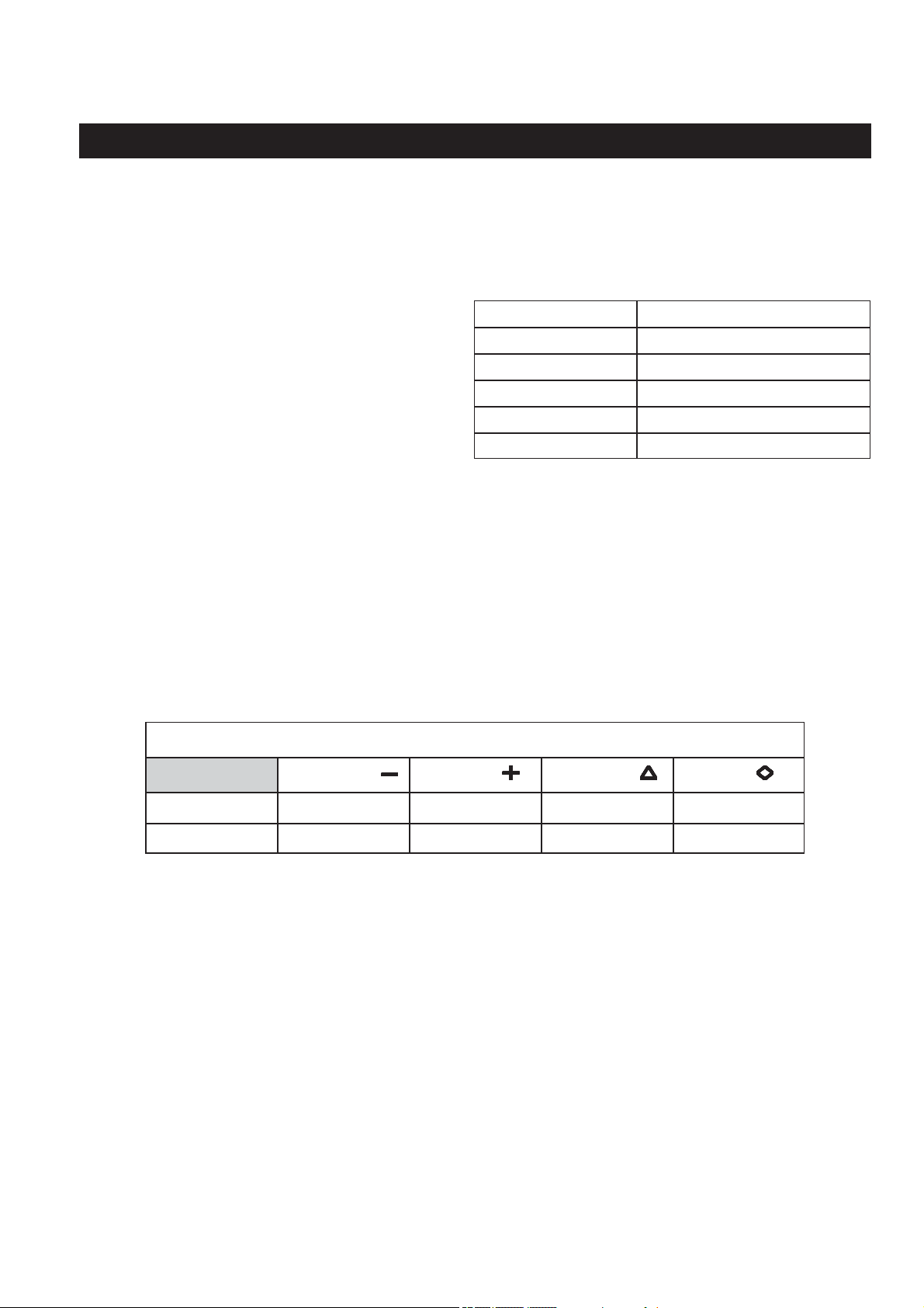
Press to confi rm the selected program and the values of the setting mode.
Press and release to select each function for display on Main Screen while running a
program, including TIME, SPEED, RPM, DISTANCE, CALORIES, WATT, and PULSE.
Turn the dial to select programs.
Turn the dial to increase or decrease the function values of the setting mode.
Turn the dial to increase or decrease the level of the workload when running a program.
Press the button and hold it down for two seconds to reset all functions to zero and skip
to initial mode.
Press to start the selected program. Press the START/STOP button to stop the program.
You can press the START/STOP button again to continue to run the current program, or
press the RESET button to skip to program selecting mode for you to select a new program.
Press to activate the pulse recovery function after training. There must be a PULSE readout
on the screen, the pulse recovery function can be activated by pressing the button.
Press to activate the body fat measurement function anytime. Input your personal data in
advance for correct readout.
COMPUTER INSTRUCTIONS
FUNCTION BUTTONS:
MODE
RESET
START/STOPBODY FAT
RECOVERY
16
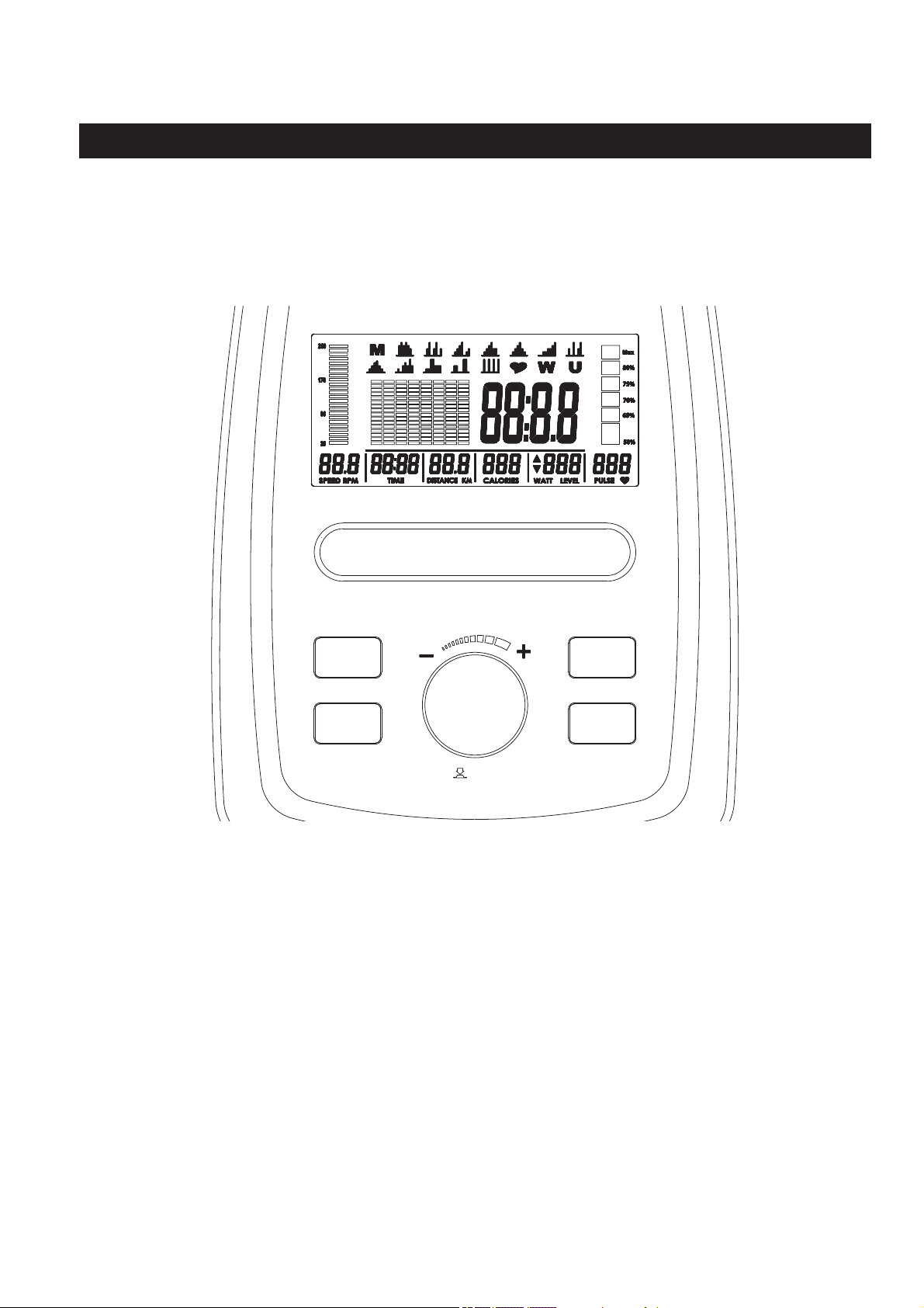
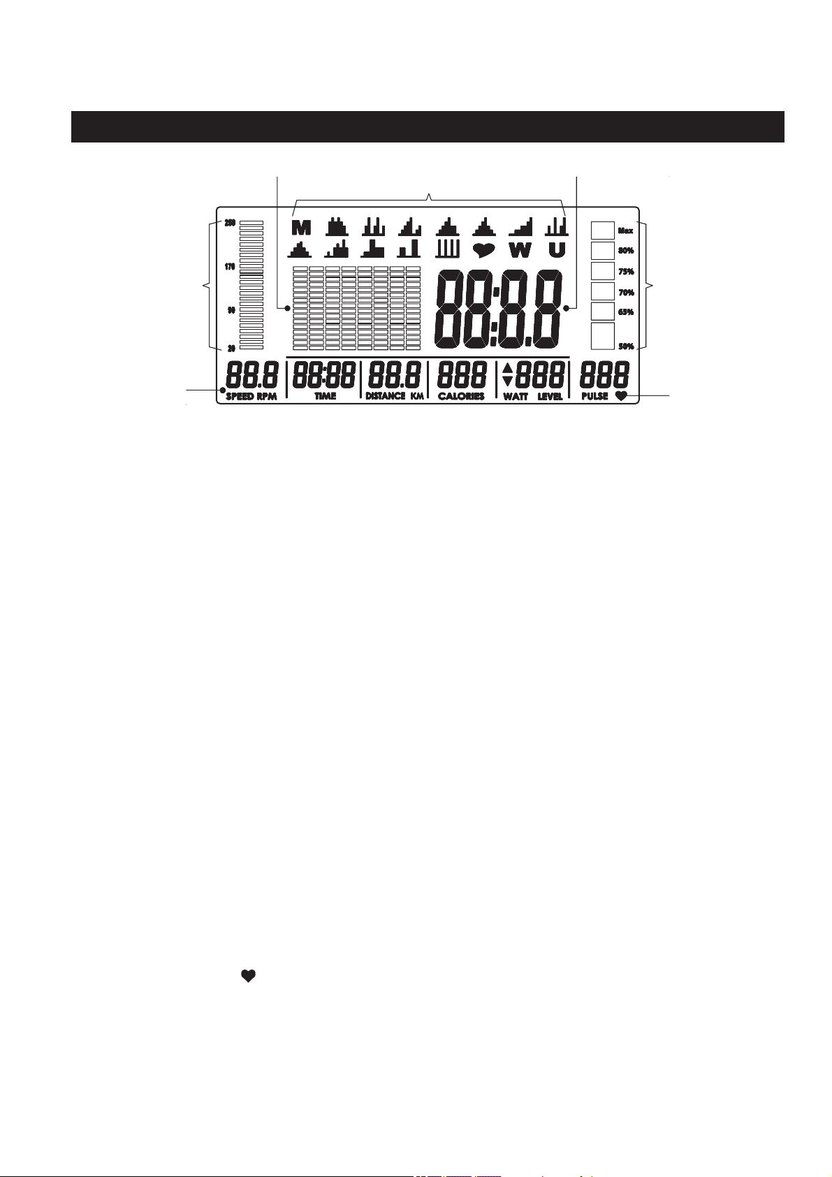
LCD DISPLAY INSTRUCTIONS
Displays fl ashing “0:00” for presetting the program time during setup, from 1:00 to 99:00
minutes, and counts down from the preset value.
If no value is preset, displays the time during exercise, from 1 second up to 99:59 minutes.
Displays the current speed from zero to 99.9 miles per hour.
Displays the rotations per minute (RPM) of the crank from zero to 999 RPM.
NOTE: The SPEED and RPM display will switch every 6 seconds while exercising.
Displays fl ashing “0.0” for presetting the function value during setup, from 1 to 99 miles,
and counts down from the preset value.
If no value is preset, displays distance up to 99.9 miles in increments of 0.1 miles.
Displays fl ashing “0” for presetting the calories consumption during setup, from 0 to 990
Kcal, and counts down from the preset value.
If no value is preset, displays the calories consumption, from zero to 999 Kcal.
NOTE: The calorie readout is an estimate for an average user. It should be used only as
a comparison between workouts on this unit.
Displays fl ashing “1” for adjusting the level of the workload of the selected program during
setup, from 1 to 16.
When running a program, displays the level of the workload when you turn the UP/DOWN
dial to adjust the workload, from 1 to 16.
Displays the amount of power being exerted from 0 to 999 watts during exercise.
Displays fl ashing “0” for presetting the LIMIT HEART RATE value during setup, from 30 to 230.
Displays the pulse rate, from 30 to 230 beats per minute during exercise.
To display PULSE, grasp the Pulse Sensors on the Handrail, one in each hand. The heart
symbol “ “ will begin blinking when the computer senses your pulse. Your pulse will be
displayed approximately fi ve (5) seconds after the heart symbol is displayed. If the heart
symbol does not appear, relax your grip or change your grip on the Pulse Sensors.
When the LIMIT HEART RATE is preset and your pulse is equal to or greater than the LIMIT
HEART RATE during workout, the computer will remind you with an audible alarm. Please
note that this is a warning for you to slow down or lower the level of resistance.
NOTE: The pulse function is a great tool to optimize your workout, but should be used as
a reference only.
COMPUTER INSTRUCTIONS
Switch to display
every 6 seconds
while exercising.
Heart Symbol
Program Profi le Main Screen
Programs
TIME:
SPEED/RPM:
DISTANCE:
CALORIES:
WATT/LEVEL
:
PULSE:
RPM Tracker
Heart Rate Tracker
17
A (Age: 1 to 99 years old) H (Height: 40 to 80 inches) W (Weight: 40 to 350 lbs)
Use the UP/DOWN dial to enter the values of your AGE, HEIGHT, and WEIGHT. Press MODE button to
confi rm the setting and move to the next item for setting.
COMPUTER INSTRUCTIONS
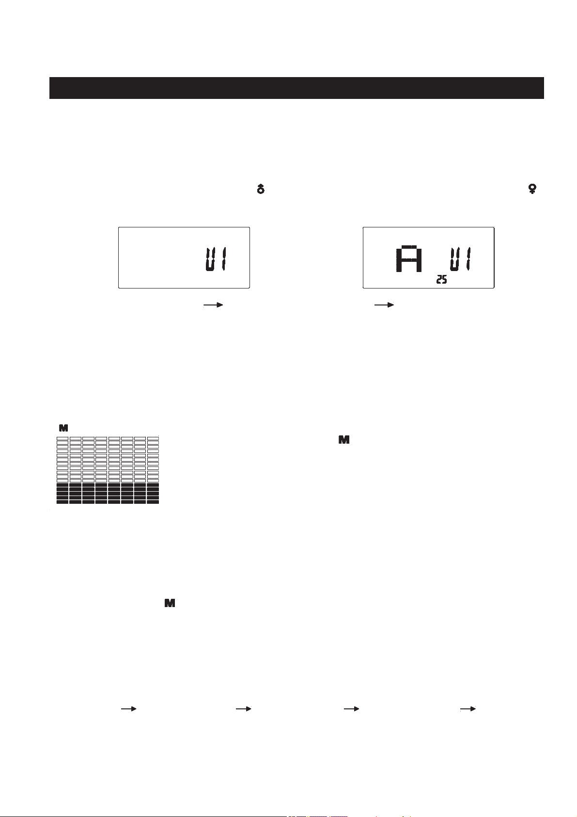
The computer uses the ADAPTER(104) as a power source. Once power is on, the computer will then
display all items on the screen and a “beep” will sound for two seconds, then skip to initial mode as shown
in illustration 1.
INPUT PERSONAL DATA: In the initial mode, the display fl ashing “U1” for you to select the “user” from
U1 to U4. For example to select “U1”, and press MODE button to confi rm and move to the next item. The
display will show the fl ashing Male symbol “
”. Turn the UP/DOWN dial to switch to Female symbol “ ”.
Press MODE button to confi rm your gender and move to the next item. The computer will go through the
input items as follows and allow you to input your personal data. Refer to illustration 2.
PROGRAM DESCRIPTION AND OPERATION
( ) MANUAL PROGRAM
MANUAL PROGRAM: Program “ ” is a manual program allowing the user to
have full manual control of the workload. Turn the UP/DOWN dial to increase
or decrease the load.
This computer contains 19 diff erent programs. You can preset the program time and the computer will divide
the time into 8 intervals. If you do not set the program time in advance, the computer will use the preset
distance 0.1 mile for each interval to run the program.
8
6
4
2
4
2
8
6
16
14
12
10
MANUAL PROGRAM OPERATION
1. Start pedaling or press any button to wake up the computer. Press the RESET button to skip to program
selecting mode to select the
manual program
. Or, press the RESET button and hold it down for two
seconds to skip to initial mode. You can select the “user”, then skip to program selecting mode to select
the m
anual program
.
2.
The manual program “ ” is always displayed fi rst. If necessary, use the UP/DOWN dial and MODE button
to select the manual program and the computer will skip to setting mode for presetting the function values.
NOTE: After using the UP/DOWN dial and MODE button to select the manual program, you can press
the START/STOP button to run the program directly without presetting any function values.
3. After pressing the MODE button, the computer will go through the input items as follows and allow you
to set the function values. Use the UP/DOWN dial and MODE button to input the values. Or press the
MODE button to pass some of the inputs.
Level (1 to 16) Time (1:00 to 99:00 min) Distance (1 to 99 mile) Calories (10 to 990 Kcal) Pulse (30 to 230)
NOTE: When the PULSE (Limit Heart Rate) is preset and your pulse is equal to or greater than the Limit
Heart Rate during workout, the computer will remind you with an audible alarm. Please note that this
is a warning for you to slow down or lower the level of resistance.
4. Now you are ready to begin exercising. The program will not start until you press the START/STOP button.
1. 2.

18
PRESET PROGRAMS: These are 12 preset automatic programs. The profi les are shown on the LCD
display of the computer. Use the UP/DOWN dial and MODE button to select the desired program.
(P04)
COMPUTER INSTRUCTIONS
(P01) (P02) (P03)
8
6
4
2
4
2
8
6
16
14
12
10
8
6
4
2
4
2
8
6
16
14
12
10
8
6
4
2
4
2
8
6
16
14
12
10
8
6
4
2
4
2
8
6
16
14
12
10
8
6
4
2
4
2
8
6
16
14
12
10
8
6
4
2
4
2
8
6
16
14
12
10
8
6
4
2
4
2
8
6
16
14
12
10
8
6
4
2
4
2
8
6
16
14
12
10
8
6
4
2
4
2
8
6
16
14
12
10
8
6
4
2
4
2
8
6
16
14
12
10
8
6
4
2
4
2
8
6
16
14
12
10
8
6
4
2
4
2
8
6
16
14
12
10
(P08) (P05) (P06) (P07)
(P12)
(P09) (P10) (P11)
PRESET PROGRAM OPERATION
1. Start pedaling or press any button to wake up the computer. Press the RESET button to skip to program
selecting mode to select one of the preset programs. Or, press the RESET button and hold it down for
two seconds to skip to initial mode. You can select the “user”, then skip to program selecting mode to
select one of the preset programs.
2. Use the UP/DOWN dial and MODE button to select the desired preset program, P01 to P12.
3. After pressing the MODE button to select the desired program, the computer will go through the input
items as follows and allow you to set the function values. Use the UP/DOWN dial and MODE button to
input the values. Or press the MODE button to pass some of the inputs.
Level (1 to 8) Time (1:00 to 99:00 min)
NOTE: After using the UP/DOWN dial and MODE button to select the desired program, you can press
the START/STOP button to run the program directly without presetting any function values.
4. After using the UP/DOWN dial to input the value of TIME, press the START/STOP button directly to run
the program to workout.
19
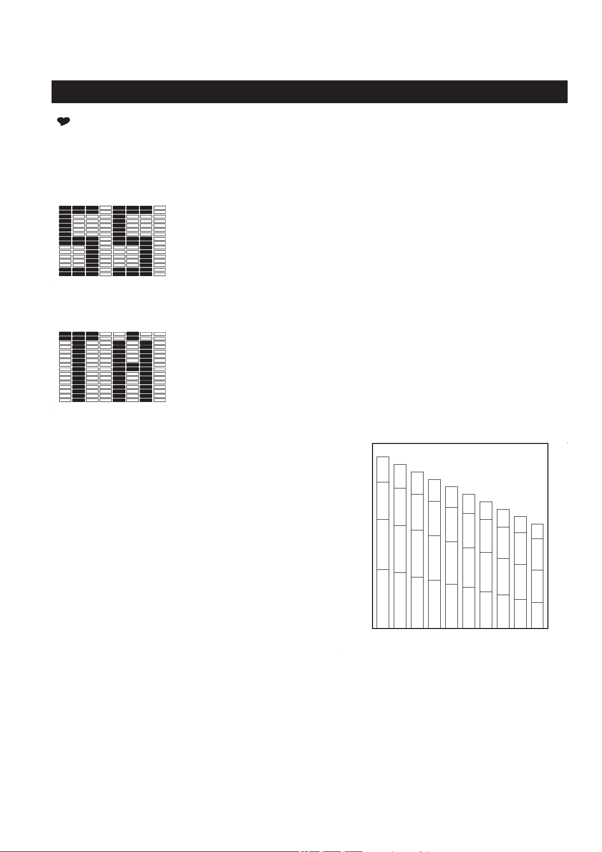
The program will monitor your pulse and adjust the
workload automatically to keep your pulse within the
zone which is plus or minus 5 Heart Beats from the
target heart rate based on the program that you selected.
For example:
If your age is 25: The maximum heart rate is 195.
If you select the Heart Rate Control Program and preset
75% of maximum heart rate: 195 x .75=146.
Heart rate zone: plus or minus 5 of 146 is 141 to 151.
The program will monitor your pulse and adjust the
workload automatically to keep your pulse within the
heart rate zone (141 to 151) during your workout.
NOTE: For cardiorespiratory training benefits, the
American College of Sports Medicine recommends
working out within a heart rate range of 55% to 90% of
maximum heart rate.
COMPUTER INSTRUCTIONS
( ) HEART RATE CONTROL PROGRAMS: There are four preset automatic heart rate control programs,
55%, 75%, 90%, and TA (Target Heart Rate). You must always hold the Pulse Sensors on the Handrail
with both hands when using the heart rate control programs. You must input your age for determining your
Maximum Heart Rate.
Target Heart Rate
Target Heart Rate Program: This program allows you to input the Target Heart
Rate you desire. Select this program, PULSE window displays fl ashing “100”
for presetting the Target Heart Rate value, from 30 to 230.
Display 55%, 75%, and 90% for option.
H. R. C. PROGRAMS
Heart Rate Control Programs: The program allows you to select the
percentage of your Maximum Heart Rate you desire, 55%, 75%, and 90%. The
computer will calculate the Target Heart Rate for the workout based on the age
and percentage of Maximum Heart Rate that you input.
8
6
4
2
4
2
8
6
16
14
12
10
8
6
4
2
4
2
8
6
16
14
12
10
3525 3020
146
150
BEATS / MINUTE
75%
139
102
143
105
107
110
55%
185
167
195
190
176
171
200
180
Max.
90%
88
91
94
55%
6050
55
45
AGE
40
85
65
158
75%
90%
144
120
149
124
131
96
135
99
153
128
140
116
Max.
160
165
175
180
162
170
155
TAEGET H.R. ZONE

20
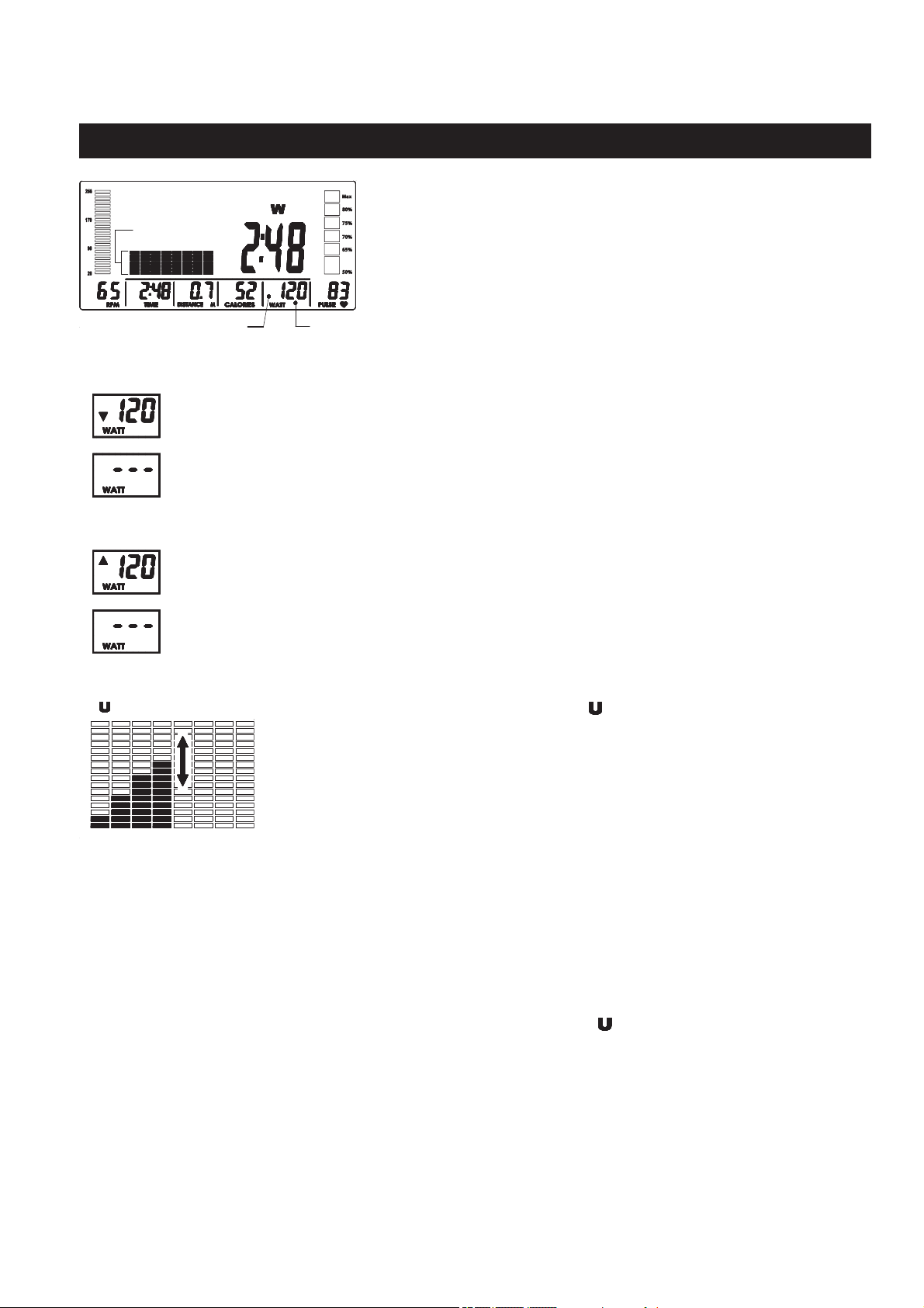
( ) TARGET WATT
TARGET WATT CONTROL PROGRAM: The program “ ” allows you to input
a target workload in WATTS. During your workout, the program will monitor your
pedaling speed and adjust the workload automatically to keep your workload,
in WATTS, as close as possible to the preset target WATT.
Select this program, WATT window displays fl ashing “120” for presetting the
target WATT value, from 10 to 350.
8
6
4
2
4
2
8
6
16
14
12
10
HEART RATE CONTROL PROGRAM OPERATION
COMPUTER INSTRUCTIONS
1. Start pedaling or press any button to wake up the computer. Press the RESET button to skip to program
selecting mode to select the heart rate control program. Or, press the RESET button and hold it down
for two seconds to skip to initial mode. You can select the “user”, then skip to program selecting mode
to select the heart rate control program.
2. Use the UP/DOWN dial and MODE button to select the heart rate control program. After pressing the
MODE button, then you can select one of the heart rate control programs, 55%, 75%, 90%, and TA
(Target Heart Rate).
3. When you select one of the percentage, 55%, 75%, or 90%, the computer will calculate the Target Heart
Rate for the workout based on the age and percentage of Maximum Heart Rate that you input. The
computer will go to the TIME setting mode to allow you to set the TIME value, from 1:00 to 99:00 min.
Use the UP/DOWN dial to input the value.
When you select the target heart rate program, “TA”, input the function values as following:
Target Heart Rate (30 to 230)
Time (1:00 to 99:00 min)
NOTE: After using the UP/DOWN dial and MODE button to select the desired program, you can press
the START/STOP button to run the program directly without presetting any function value.
4. After using the UP/DOWN dial to input the value of TIME, press the START/STOP button directly to run
the program to workout. Always hold the Pulse Sensors on the
Handrail with both hands.
TARGET WATT CONTROL PROGRAM OPERATION
1. Start pedaling or press any button to wake up the computer. Press the RESET button to skip to program
selecting mode to select the target watt control program. Or, press the RESET button and hold it down
for two seconds to skip to initial mode. You can select the “user”, then skip to program selecting mode
to select the target watt control program.
2. Use the UP/DOWN dial and MODE button to select the program “
” (Target Watt Control Program).
3. After pressing the MODE button, the computer will go through the input items as follows and allow you
to set the function values. Use the UP/DOWN dial and MODE button to input the values. Or press the
MODE button to pass some of the inputs.
Target Watt (10 to 350 watts)
Time (1:00 to 99:00 min)
NOTE: After using the UP/DOWN dial and MODE button to select the desired program, you can press
the START/STOP button to run the program directly without presetting any function values.
4. After using the UP/DOWN dial to input the value of TIME, press the START/STOP button directly to run
the program to workout.
21
COMPUTER INSTRUCTIONS
Target WattNo Arrow Indicator here
The program will
adjust the workload
automatically.
If the Arrow
Indicator appears as follows, it means your pedaling speed is too low. Please pedal
faster.
P
edaling speed is too low, almost out of the range that the program can adjust the workload for
you. Please pedal
faster.
P
edaling speed is too low and out of the range that the program can adjust the workload for you,
and
the computer will remind you with an audible alarm
. Please pedal
faster.
If the Arrow
Indicator appears as follows, it means your pedaling speed is too fast. Please pedal
slower.
P
edaling speed is too fast, almost out of the range that the program can adjust the workload for
you. Please pedal
slower.
P
edaling speed is too fast and out of the range that the program can adjust the workload for you,
and
the computer will remind you with an audible alarm
. Please pedal
slower.
( ) USER SETTING
USER SETTING PROGRAM: Program “ ” is an automatic program that allows
the user to manually preset each of the 8 intervals. Select this program, use
the UP/DOWN dial and MODE button to edit the program profi le. The program
profi le will be stored in the memory after setup. You can modify the profi le
anytime once you select this program.
When running the program, you still can use the UP/DOWN dial to increase
or decrease the load level of each interval and these changes will be stored in
memory.
8
6
4
2
4
2
8
6
16
14
12
10
USER SETTING PROGRAM OPERATION
1. Start pedaling or press any button to wake up the computer. Press the RESET button to skip to program
selecting mode to select the user setting program. Or, press the RESET button and hold it down for two
seconds to skip to initial mode. You can select the “user”, then skip to program selecting mode to select
the user setting program.
2. Use the UP/DOWN dial and MODE button to select the program “
” ( User Setting Program).
3. After pressing the MODE button, interval 1 will begin fl ashing. Use the UP/DOWN dial to set the load
for interval 1. Press the MODE button to confi rm and proceed to the next interval. Use the UP/DOWN
dial and MODE button to set the load for each interval. When all the intervals are set, press the MODE
button and hold it down for two seconds to skip to setting mode for presetting the function value of TIME,
from 1:00 to 99:00 min. Or, press the START/STOP button to run the program directly without presetting
the TIME function value.
4. After using the UP/DOWN dial to input the value of TIME, press the START/STOP button directly to run
the program to workout.
When running the target watt control program, the program
will monitor your pedaling speed and adjust the workload
automatically to keep your workload as close as possible to
the preset target WATT. For example, if the preset target WATT
is 120 and you pedal with proper speed, the display will be as
shown in the illustration. There should be no Arrow
Indicator
appearing on the display.

22
COMPUTER INSTRUCTIONS
OPERATION NOTES
1. When running a program, the main screen automatically scans TIME, SPEED, RPM, DISTANCE,
CALORIES, WATT, and PULSE in sequence with a change every six seconds. You can press the MODE
button to select each function for display on the Main Screen, but the SCAN function will stop. Quickly
press the START/STOP button twice to activate the SCAN function again.
2. You may preset values for several functions. The preset function values will start to count down once
you press the START/STOP button to start exercising. Preset values will only count down, they will not
count up. When you complete one of the preset functions, the computer will remind you with an audible
alarm for eight seconds and stops running the program. Press any button to stop the audible alarm.
Two possible options follow: Option A: press the START/STOP button to continue to run the current
program. The value of this completed function will count down from its preset value again, while the other
preset functions will continue to count down until you reach the next preset function. Option B: use the
UP/DOWN dial and MODE button to reset the function values or to select a new program.
3. To stop a running program, press the START/STOP button. In this mode, you can press the START/
STOP button again to continue to run the current program. If you want to restart with a new program,
press the RESET button to skip to program selecting mode to select a new program.
4. The computer will shut off automatically after 4 minutes of inactivity and all function values will be kept.
Press the START/STOP button to continue to run the current program. Or, press the RESET button to
skip to program selecting mode to select a new program.
5. When running a program without presetting the program time, the program will stop running the program
after 4 seconds of inactivity. However, the TIME will continue to count up for four minutes, then shut off
the computer automatically. You can restart the program by pedaling within these 4 minutes.
6. When running a program and presetting the program time, if you stop pedaling, the program will continue
to run for 4 minutes, then shut off the computer automatically. You can restart the program by pedaling
within these 4 minutes.
7. If the computer malfunctions, unplug the adaptor and plug it back in to reset.
23
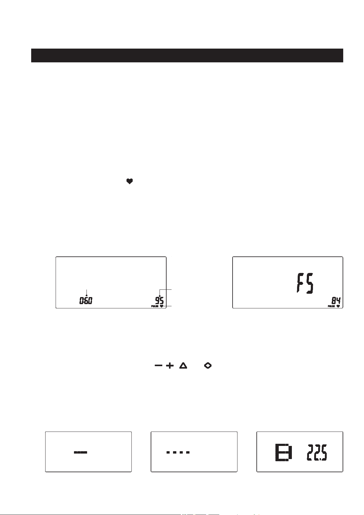
The readout should only be used as a comparison between workouts. It can be used right after any aerobic
exercise. Stop exercising before starting this function.
To start the pulse recovery function, grasp the Pulse Sensors on the Handrail, one in each hand. Your
pulse will be displayed approximately fi ve (5) seconds after the heart symbol is displayed. Then press the
RECOVERY button and continue to grasp the Pulse Sensors correctly. During the pulse recovery function,
only PULSE and TIME are working and the display will be as shown in illustration 3. TIME will count down
from 0:60 and the heart symbol “ “ will be blinking. When the TIME reaches 0, the computer will show your
pulse recovery condition from F1.0 to F6.0. See illustration 4. Press RECOVERY button to exit the display.
NOTE:
COMPUTER INSTRUCTIONS
The PULSE RECOVERY function measures how quickly you return to a resting heart rate after exercising.
You can use this function to measure improvement as you get into shape. The computer will monitor your
heart rate for 60 seconds and calculate a pulse recovery value from F1 to F6.
F1.0 = Excellent F2.0 = Good F3.0 = Fair
F4.0 = Below Average F5.0 = Not Good F6.0 = Poor
3. 4.
PULSE RECOVERY FUNCTION
Current
heart rate
Heat Symbol
1. When the PULSE readout is shown on the screen, you can press the RECOVERY button at any
time to run pulse recovery program, even during your exercising and running other programs.
2. You can quit the pulse recovery function by pressing the RECOVERY button.
3. Once the pulse recovery function starts, the TIME will count down from 60 seconds to zero
even if you remove your hands from the Pulse Sensors. If no pulse signal is available, F6.0 will
displayed as the pulse recovery condition.
5. 7.
If you are running a program, press the START/STOP button to stop the program. To start the body fat
measurement, grasp the Pulse Sensors on the Handrail, one in each hand. Then press the BODY FAT button
and continue to grasp the Pulse Sensors correctly. After 8 seconds, the computer will display the information
for BMI, FAT%, and BODY FAT symbol ( , , , and ), refer to illustration 7. This information will
cycle for 30 seconds, press the BODY FAT button to exit the display. Refer to the following illustrations for
the body fat measurement displays.
NOTE:
1. You can quit the body fat measurement by pressing the BODY FAT button.
2.
If you do not hold properly or remove your hands from the Pulse Sensors. If no signal is available, an
error code E-1 will displayed. Press the BODY FAT button and do the body fat measurement again.
3. If the BMI and FAT% result is below 5, or exceeds 50, an error code E-4 will displayed.
TIME
(Count down
from 60 sec.)
BODY FAT MEASUREMENT
6.
Not grasping the Pulse
Sensors correctly.
Program is working,
wait 8 seconds.
Body fat measurement result.
POWER SOURCE:
The COMPUTER(1) uses the ADAPTER(104) as a power source. Use the Stamina® Magnetic Recumbent
Exercise Bike 845 with the ADAPTER(104) plugged into an electrical outlet.
24
UNDERSTANDING THE READOUT INFORMATION
2. BODY FAT %
Your body fat percentage is simply the percentage of fat your body contains. If you are 150 pounds and
10% fat, it means that your body consists of 15 pounds fat and 135 pounds lean body mass (bone, muscle,
organ tissue, blood and everything else).
A certain amount of fat is essential to bodily functions. Fat regulates body temperature, cushions and
insulates organs and tissues and is the main form of the body’s energy storage. The table describes body
fat ranges and their associated categories.
Body Mass Index is a height/weight formula used by health and weight professionals around the world to
assess a person’s body weight. From your body mass index number you can see if you are underweight,
normal weight, overweight or obese.
1. BMI (BODY MASS INDEX)
Under 20 (19 for women)
Between 20 and 24.99
Between 25 and 29.99
Between 30 and 34.99
Between 35 and 39.99
40 and above
Underweight
Normal Weight
Overweight
Obese Class 1
Obese Class 2
Extreme Obesity
BMI conclusions vary slightly according to gender.
Here is a general summary of weight-status
based on BMI.
COMPUTER INSTRUCTIONS
General Body Fat Percentage Categories
Classifi cation
Men (fat %)
Women (fat %)
Essential Fat
“ ”
2 - 9%
10 - 19%
Standard “ ”
10 - 19%
20 - 29%
Acceptable
“ ”
20 - 24%
30 - 34%
Obese “ ”
25% plus
35% plus

25
1. To store the
Stamina® Magnetic Recumbent Exercise Bike 845,
simply keep it in a clean dry place.
2. The minimum rest dimensions of the
Stamina® Magnetic Recumbent Exercise Bike 845
are
approximately 47.9 inches long x 23.6 inches wide x 46.3 inches tall. These dimensions will vary.
Please measure your
Stamina® Magnetic Recumbent Exercise Bike 845
if exact dimensions are
needed.
3. To move the
Stamina® Magnetic Recumbent Exercise Bike 845,
lift up the
REAR STABILIZER(13)
and use the Wheels on the
FRONT STABILIZER(11).
The safety and integrity designed into the
Stamina® Magnetic Recumbent Exercise Bike 845
can only
be maintained when the
Stamina® Magnetic Recumbent Exercise Bike 845
is regularly examined for
damage and wear. Special attention should be given to the following:
1. Use the
UP/DOWN
dial and
MODE
button on the
COMPUTER(1)
to select a program and verify that
the magnetic system functions properly and provides diff erent tensions.
2. Use a wrench to verify that the pedals are tightened securely. If tightening is required, remember that
the left pedal has left hand threads and is tightened by turning counterclockwise.
3. Do not step on any portion of the plastic cover when getting on or off the
Stamina® Magnetic
Recumbent Exercise Bike 845.
This can cause the plastic cover to crack.
4. Verify that all nuts and bolts are present and properly tightened. Replace missing nuts and bolts.
Tighten loose nuts and bolts.
5. Verify that the
CAUTION LABEL(114)
is in place and easy to read. Call Stamina Products immediately
at
1-800-375-7520
for a replacement
CAUTION LABEL(114)
if it is missing or damaged.
6. It is the sole responsibility of the user/owner to ensure that regular maintenance is performed.
7. Worn or damaged components must be replaced immediately or the
Stamina® Magnetic Recumbent
Exercise Bike 845
removed from service until repair is made.
8. Only Stamina Products supplied components should be used to maintain/repair the
Stamina®
Magnetic Recumbent Exercise Bike 845.
9. Keep your
Stamina® Magnetic Recumbent Exercise Bike 845
clean by wiping it off with an
absorbent cloth after use.
STORAGE
MAINTENANCE

How you begin your exercise program depends on your physical condition. If you have been inactive for
several years or are severely overweight, start slowly and increase your workout time gradually. Increase
your workout intensity gradually by monitoring your heart rate while you exercise.
Initially you may only be able to exercise within your target zone for a few minutes; however, your aerobic
capacity will improve over the next six to eight weeks. It is important to pace yourself while you exercise
so you don't tire too quickly.
Measure your heart rate periodically during your workout by stopping the
exercise but continuing to move your legs or walk around. Place two or
three fi ngers on your wrist and take a six second heartbeat count. Multiply
the results by ten to fi nd your heart rate. For example, if your six second
heartbeat count is 14, your heart rate is 140 beats per minute. A six second
count is used because your heart rate will drop rapidly when you stop
exercising. Adjust the intensity of your exercise until your heart rate is at the
proper level.
wrist pulse
Remember to follow these essentials:
Have your doctor review your training and diet programs.
Begin your training program slowly with realistic goals that have been set by you and your physician.
Warm up before you exercise and cool down after you work out.
Take your pulse periodically during your workout and strive to stay within a range of 60% (lower
intensity) to 90% (higher intensity) of your maximum heart rate zone. Start at the lower intensity, and
build up to higher intensity as you become more aerobically fi t.
If you feel dizzy or lightheaded you should slow down or stop exercising.
To determine if you are working out at the correct intensity, use a heart rate monitor or use the table
below. For effective aerobic exercise, your heart rate should be maintained at a level between 60%
and 90% of your maximum heart rate. If just starting an exercise program, work out at the low end of
your target heart rate zone. As your aerobic capacity improves, gradually increase the intensity of your
workout by increasing your heart rate.
CONDITIONING GUIDELINES
Target Heart Rate Zone Estimated by Age*
* For cardiorespiratory training benefits, the American College of Sports Medicine recommends
working out within a heart rate range of 55% to 90% of maximum heart rate. To predict the
maximum heart rate, the following formula was used: 220 - Age = predicted maximum heart rate
20 years
25 years
30 years
35 years
40 years
45 years
50 years
55 years
60 years
65 years
70 years
Average Maximum
Heart Rate 100%
Age
110-180 beats per minute
107-175 beats per minute
105-171 beats per minute
102-166 beats per minute
99-162 beats per minute
97-157 beats per minute
94-153 beats per minute
91-148 beats per minute
88-144 beats per minute
85-139 beats per minute
83-135 beats per minute
200 beats per minute
195 beats per minute
190 beats per minute
185 beats per minute
180 beats per minute
175 beats per minute
170 beats per minute
165 beats per minute
160 beats per minute
155 beats per minute
150 beats per minute
Target Heart Rate Zone
(55%-90% of Maximum Heart Rate)
26
WARM-UP and COOL-DOWN
Warm-Up
The purpose of warming up is to prepare your body for exercise and to minimize injuries.
Warm up for two to fi ve minutes before strength training or aerobic exercising. Perform activities that
raise your heart rate and warm the working muscles. Activities may include brisk walking, jogging,
jumping jacks, jump rope, and running in place.
Stretching
Stretching while your muscles are warm after a proper warm-up and again after your
strength or aerobic training session is very important. Muscles stretch more easily at these times
because of their elevated temperature, which greatly reduces the risk of injury. Stretches should be held
for 15 to 30 seconds. Do not bounce.
Suggested Stretching Exercises
Remember to always check with your physician before starting any exercise program.
Cool-Down
The purpose of cooling down is to return the body to its normal, or near normal, resting
state at the end of each exercise session. A proper cool-down slowly lowers your heart rate and allows
blood to return to the heart. Your cool-down should include the stretches listed above and should be
completed after each strength training session.
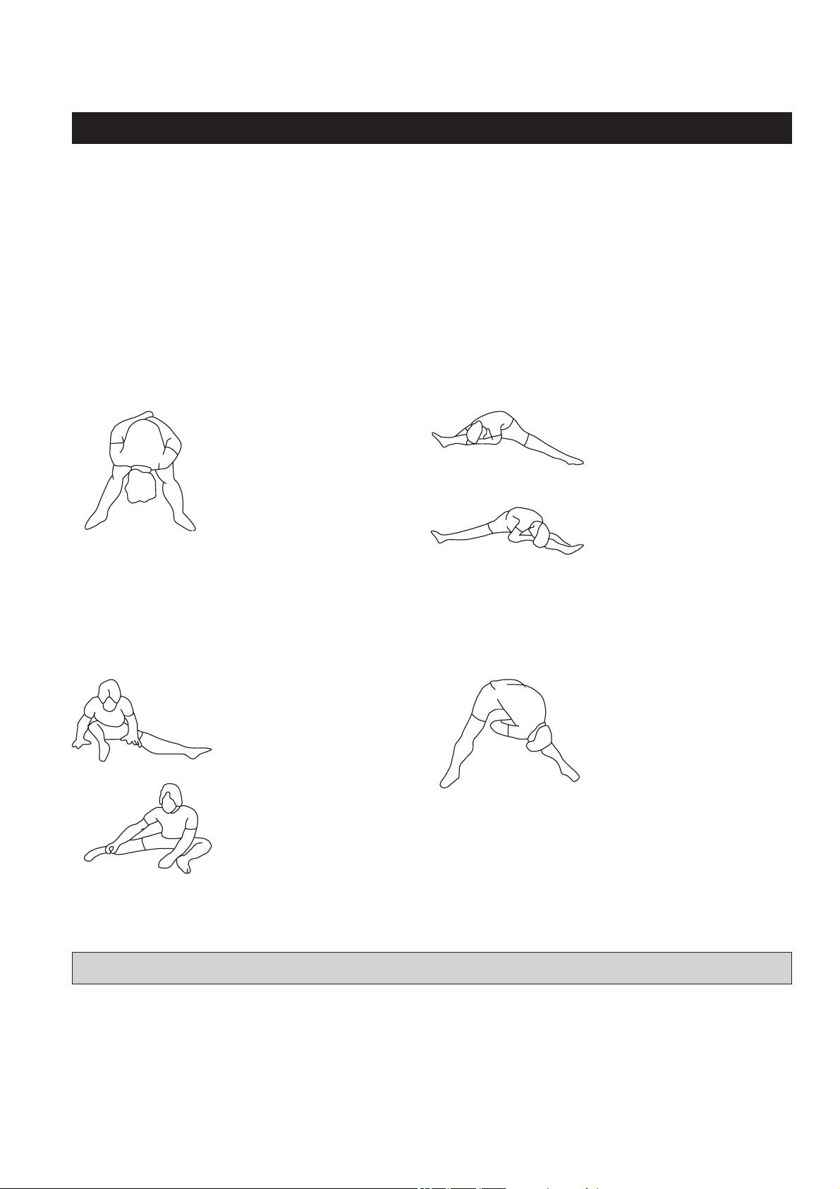
Lower Body Stretch
Place feet shoulder-width
apart and lean forward.
Keep this position for 30
seconds using the body as a
natural weight to stretch the
backs of the legs.
DO NOT BOUNCE!
When the pull on the back of
the legs lessens, gradually
try a lower position.
Floor Stretch
While sitting on the fl oor,
open the legs as wide as
possible. Stretch the upper
body toward the knee on the
right leg by using your arms
to pull your chest to your
thighs. Hold this stretch 10
to 30 seconds.
DO NOT BOUNCE!
Do this stretch 10 times.
Repeat the stretch with the
left leg.
Bent Over Leg Stretch
Stand with feet shoulder-
width apart and lean forward
as illustrated. Using the
arms,
gently
pull the upper
body towards the right leg.
Let the head hang down.
DO NOT BOUNCE!
Hold the position a minimum
of 10 seconds. Repeat
pulling the upper body to
the left leg. Do this stretch
several times slowly.
Bent Torso Pulls
While sitting on the fl oor,
have legs apart, one leg
straight and one knee bent.
Pull the chest down to touch
the thigh on the leg that is
bent, and twist at the waist.
Hold this position at least 10
seconds. Repeat 10 times
on each side.
27
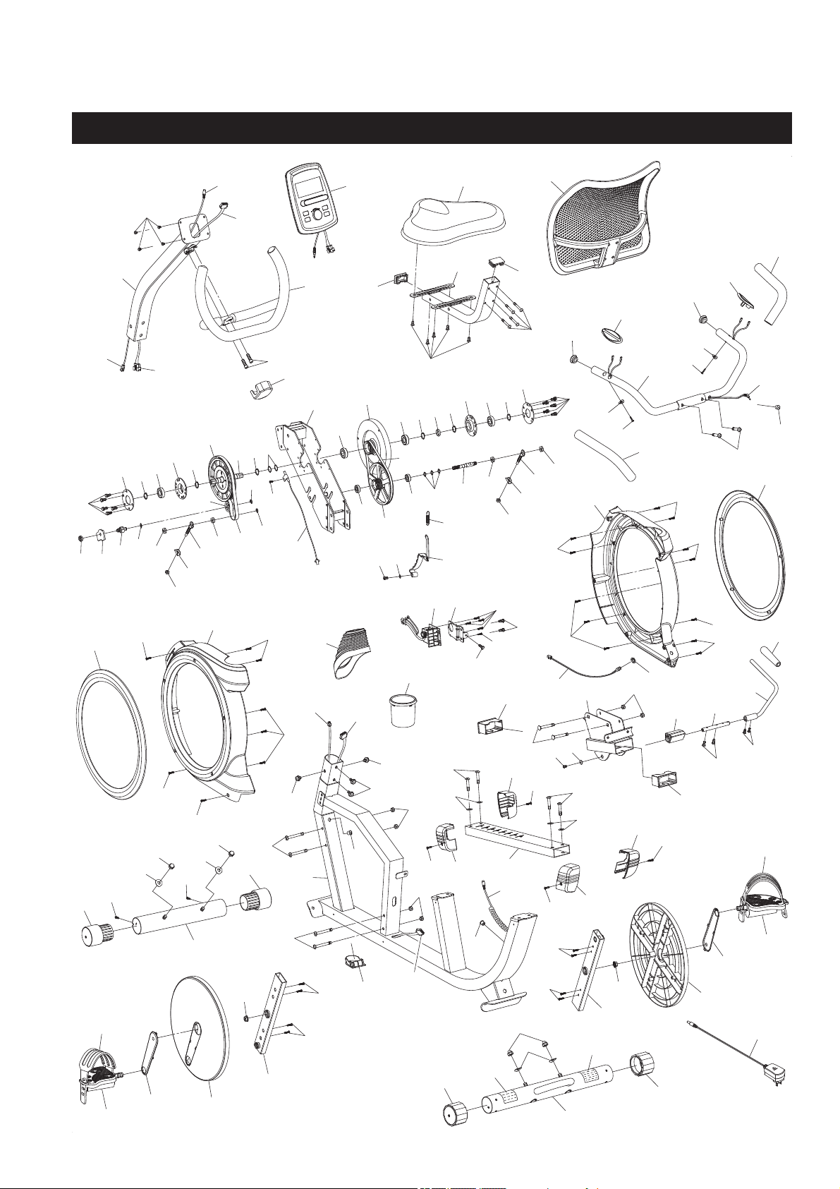
PRODUCT PARTS DRAWING
28
FRONT
BACK

PART# PART NAME QTY
PARTS LIST
29
1 Computer 1
2 Upright 1
3 Handlebar 1
4 Screw, Round Head (M5 x 0.8 x 10mm) 5
5 Bolt, Socket Head (M8 x 1.25 x 25mm) 2
6 Handlebar Cover 1
7 Bolt, Button Head w/ Washers (M8 x 1.25 x 16mm) 4
8 Left Cover 1
9 Decoration Ring 2
10 Main Frame 1
11 Front Stabilizer 1
12 Screw, Round Head (M4 x 12mm) 18
13 Rear Stabilizer 1
14 Left Crank 1
15 Seat Slider 1
16 Seat Frame 1
17 Lever 1
18 Handrail 1
19 Seat 1
20 Seat Back 1
21 Rectangular Plug (30mm x 50mm) 2
22 Bolt, Button Head (M6 x 1 x 13mm) 7
23 Bolt, Button Head (M6 x 1 x 45mm) 4
24 Slider Bushing 2
25 Carriage Bolt (M8 x 1.25 x 66mm) 2
26 Nylock Nut (M8 x 1.25) 6
27 Control Motor 1
28 Plastic Washer (ø6.5 x ø16 x 2mm thick) 2
29 Adjustment Block 1
30 Lever Connector 1
31 Bolt, Hex Head (M6 x 1 x 15mm) 2
32 Round Plug (25mm) 2
33 Lever Hand Grip 1
34 Rail 1
35 Bolt, Button Head (M8 x 1.25 x 40mm) 4
36 Washer (M8) 4
37 Bolt, Hex Head (M8 x 1.25 x 72mm) 2
38 Bolt, Hex Head (M8 x 1.25 x 77mm) 2
39 Bolt, Hex Head w/ Washers (M6 x 1 x 16mm) 12
40 Bearing Housing Cover 2
41 C Ring (ø20mm) 6
42 Bearing (6004Z) 2
43 Bearing Housing 2
44 Crank Pulley 1
45 Crank Shaft 1
46 Transmission Frame 1
47 C Ring (ø15mm) 1
48 Magnetic Flywheel 1

PART# PART NAME QTY
PARTS LIST
30
49 Wavy Washer (S20) 2
50 Plastic Spacer (ø20.1 x ø27 x 7mm) 1
51 Screw, Round Head (M4 x 10mm) 1
52 Mounting Bracket 1
53 Sensor Wire 1
54 Nylock Nut (M10 x 1.5) 1
55 Idler Shaft Support Plate 1
56 Idler Shaft 1
57 Wavy Washer (S15) 1
58 C Ring (ø10mm) 1
59 V-Ribbed Belt (240-J5) 1
60 Bearing (6202RS) 1
61 Flange Nut (M10 x 1.0) 2
62 Eyelet Bolt (M8 x 1.25 x 63mm) 2
63 Nut (M10 x 1.5) 4
64 Tension Bracket 2
65 Nut (M8 x 1.25) 2
66 Bearing (6000Z) 2
67 Pulley 1
68 Screw, Round Head (M4 x 10mm) 2
69 V-Ribbed Belt (230-J3) 1
70 Pulley Shaft 1
71 Magnetic Brake 1
72 Plug Nut 1
73 Spring 1
74 Bolt, Round Head (M6 x 1 x 10mm) 1
75 Extension Control Cable (650mm long) 1
76 D Shape Plug 1
77 Wheel Cap 2
78 Acorn Nut (M10 x 1.5) 4
79 Arc Washer (M10) 4
80 Screw, Round Head (M3 x 14mm) 4
81 Crank Disc 2
82 Crank Decoration 2
83 Upright Cover 1
84 Leveling Cap 2
85 Screw, Round Head (M4 x 16mm) 2
86 Bottle Tray 1
87 Left Front Rail Cover 1
88 Grommet Plug 3
89 Wavy Washer (S10) 3
90 Left Back Rail Cover 1
91 Left Pedal 1
92 Left Pedal Strap 1
93 Bearing (6904Z) 2
94 Screw, Round Head (M3 x 10mm) 1
95 Screw, Round Head (M4 x 20mm) 12
96 Pulse Sensor Plate 2

PART# PART NAME QTY
PARTS LIST
97 Foam Tube (ø23 x ø600 x 3mm thick) 2
98 Arc Washer (M4) 2
99 Screw, Round Head Self-Drilling (M4 x 22mm) 2
100 Pulse Sensor Extension Wire (1900mm long) 1
101 Pulse Sensor Connection Wire (650mm long) 1
102 Bolt, Button Head (M8 x 1.25 x 36.5mm) 2
103 Bolt, Hex Head (M6 x 1 x 16mm, with threadlocker) 1
104 Adapter, Output 9V, 500mA 1
105 Control Cable (950mm long) 1
106 Power Wire 1
107 Pulse Sensor Wire 1
108 Right Cover 1
109 Right Crank 1
110 Right Front Rail Cover 1
111 Right Back Rail Cover 1
112 Right Pedal 1
113 Right Pedal Strap 1
114 Caution Label 1
115 Serial Decal 1
117 Allen Wrench (4mm) 1
118 Allen Wrench (6 mm) w/ Screwdriver 1
119 Wrench 1
120 Opening Wrench 1
121 Manual 1
31

LIMITED WARRANTY
WARRANTY
MODEL 15-4845
32
Stamina Products, Inc. (“Stamina”) warrants to the original purchaser that this product will be free from
defects in materials and workmanship that arise under normal use, service, proper assembly and proper
operation in accordance with product warnings/instructions for a period of 90 days on the parts and three
years on the frame from the date of the original purchase from an authorized retailer.
THIS WARRANTY
SHALL NOT APPLY TO ANY PRODUCT WHICH HAS BEEN SUBJECT TO COMMERCIAL USE,
ABUSE, MISUSE, ALTERATION OF ANY KIND OR TO ANY DEFECT OR CHANGE CAUSED BY
IMPROPER ASSEMBLY, REPAIR, REPLACEMENT, SUBSTITUTION OR USE WITH PARTS NOT
PROVIDED BY STAMINA.
Commercial use includes use of product in athletic clubs, health clubs, spas,
gyms, and all other public or semipublic facilities whether or not the product’s use is in furtherance of a
profi t making enterprise, and all other use which is not for personal purposes.
To implement this limited warranty, send a written notice stating your name, date, and place of purchase
and a brief description of the defect along with your receipt to Stamina Products, Inc. 2040 N Alliance
Ave, Springfi eld, Missouri, USA, MO 65803, or email us at customer[email protected], or call
us at 1-800-375-7520. If the defect is covered under this limited warranty, you will be requested to return
the product or part to us for free repair or replacement at our option.
NO ACTION FOR BREACH OF THIS LIMITED WARRANTY MAY BE COMMENCED MORE
THAN ONE (1) YEAR AFTER THE DATE THE ALLEGED BREACH WAS OR SHOULD HAVE
BEEN DISCOVERED. NO ACTION FOR BREACH OF ANY IMPLIED WARRANTY (INCLUDING
MERCHANTABILITY AND FITNESS FOR A PARTICULAR PURPOSE) MAY BE COMMENCED MORE
THAN ONE (1) YEAR AFTER DELIVERY OF THE PRODUCT TO THE PURCHASER.
These warranties
are not transferable.
IF ANY PART OF THE PRODUCT IS NOT IN COMPLIANCE WITH THIS LIMITED
WARRANTY OR ANY IMPLIED WARRANTY, THE REMEDY OF REPAIR OR REPLACEMENT IS THE
EXCLUSIVE REMEDY.
If any claim is made under this limited warranty or any implied warranty, Stamina
reserves the right to require the product to be returned for inspection, at the purchaser’s expense, to
Stamina’s premises in Springfield, Missouri. Return of the enclosed warranty registration card is not
required for warranty coverage, but is merely a way of establishing the date and place of purchase.
Stamina
SHALL NOT BE LIABLE FOR THE LOSS OF USE OF ANY PRODUCT, LOSS OF TIME,
INCONVENIENCE, COMMERCIAL LOSS OR ANY OTHER INDIRECT, CONSEQUENTIAL, SPECIAL
OR INCIDENTAL DAMAGES DUE TO BREACH OF THE ABOVE WARRANTY OR ANY IMPLIED
WARRANTY.
THIS LIMITED WARRANTY IS THE ONLY EXPRESS WARRANTY. NO ORAL OR WRITTEN
INFORMATION GIVEN BY STAMINA, ITS AGENTS OR EMPLOYEES, SHALL CREATE A WARRANTY
OR IN ANY WAY INCREASE THE SCOPE OF THIS WARRANTY.
This warranty gives you specifi c legal
rights, and you may also have other legal rights which vary from state to state.
ANY OTHER RIGHT
WHICH YOU MAY HAVE, INCLUDING ANY IMPLIED WARRANTY OF MERCHANTABILITY OR
FITNESS FOR A PARTICULAR PURPOSE, IS LIMITED IN DURATION TO THE DURATION OF THIS
WARRANTY.
The laws in some states aff ect the disclaimer or limitation of implied warranties and consequential and
incidental damages. If any such law is found applicable, the foregoing disclaimers and limitations of and
on implied warranties and consequential and incidental damages shall be deemed to be modifi ed to the
extent necessary to comply with applicable law.

NOTES
33
Model Number: ...................................................................................... Serial Number: .............................................................................................
Product Name: ..................................................................................................................................................................................................................................
Place Purchased: ..............................................................................................................................................................................................................................
Date of Purchase: .................................................................................. Purchase Price: ............................................................................................
First Name: ............................................................................................ Last Name: ...................................................................................................
City: .................................................................. State: ................................................................ Zip Code: .................................................
Email Address: ....................................................................................... Phone #: ( ) ......................................................................................
Would you like to receive email information or special off ers from Stamina Products?* ____Yes ____No
*If yes, be sure your email address is included above.
Stamina Products, Inc.
2040 N Alliance Ave, Springfi eld, MO 65803
If there are missing or damaged parts, you can go to parts.staminaproducts.com and order those parts. If you have questions,
please contact customer care. Do not return the product. To order parts by mail, fill out the sheet below and fax it to
417-889-8064. The part will be mailed to your address.
Mr./Ms: ..............................................................................................................................................................................................................................................
Address: ........................................ ............................................................................................. Apt. #:..........................................................................
City: .................................................................. State: ................................................................ Zip Code: .................................................
IMPORTANT : We require your phone number to process the order!
Phone #: ( ) ................................................................................ Work Phone #: ( ) .............................................................................
Date of Purchase: ..................................................................................
Model #: ............................................................................................................................................................................................................................................
Purchased From: ..............................................................................................................................................................................................................................
IMPORTANT: Before fi lling out the portion below, make sure you have the correct information.
Refer to the parts list to make sure you're ordering the right parts!
Stamina Products, Inc.
2040 N Alliance Ave, Springfi eld, MO 65803
Detach and Mail or Fax the Form Above
TO CONTACT CUSTOMER CARE
For your convenience, Stamina’s customer care representatives can be reached by email at
customer.care@staminaproducts.
com
or by phone at 1-800-375-7520 (in the U.S.). Our customer care representatives are available Monday through Thursday
from 7:30 a.m. until 5:00 p.m., and Friday 8:00 a.m. until 3 p.m. Central Time.
TO REGISTER YOUR PRODUCT
Would you like to recieve email information or special off ers from Stamina Products? Register at contact.staminaproducts.com
TELEPHONE
CUSTOMER CARE
Tel: 1 (800) 375-7520
FAX
CUSTOMER CARE
Fax: (417) 889-8064
MAIL
STAMINA PRODUCTS, INC.
ATTN: Customer Care
2040 N Alliance Ave, Springfi eld, MO 65803
ONLINE
CUSTOMER CARE
customer[email protected]
www.staminaproducts.com
To enact your warranty, please register your product by going to register.staminaproducts.com. Please have your product model
number (printed on the cover of this owner’s manual) and the serial number (printed on the black and white sticker on your
product) ready.
If you don’t have internet access, you can call customer care at 1-800-375-7520, or fi ll out and mail the product registration form
below to Stamina Products, Inc.; 2040 N Alliance Ave, Springfi eld, MO 65803.
PRODUCT REGISTRATION FORM
TO ORDER PARTS
Detach and Mail or Fax the Form Below
PARTS ORDER FORM
PART # DESCRIPTION QUANTITY
1 Rear Unit Assembly 1
EXAMPLE: