Loading ...
Loading ...
Loading ...

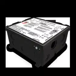
WIRING YOUR F50-ATS:
50amp 125/2 VAC Wiring
Ground = Bare copper wire or green
Neutral = White
Live/Hot L1 = Black
Live/Hot L2 = Red
50amp 12
VAC Wiring
Ground = Bare copper wire or green
Neutral = White
Live/Hot = Black
Using the quick reference wiring guide on the lid of the ATS box, arrange the wires to be
fed into the ATS for connection at the corresponding terminals.
Generator in
Shore Power in
Line/feed out
Ensure to feed the wires through the cable strains when they enter to ATS box.
Shore power and generator cables should be fed into the ATS from the side marked
on the box sticker.
The line out wires will enter the ATS from the opposite side.
See below diagram for wiring layout.
Strip 4” of outer jacket from each of the incoming cables.
Strip ½” of jacket from each of the wire conductors.
Connect the colored wires to the ATS terminals using the diagram above
Using your #2 (Robertson’s) square head torque Screwdriver, tighten the terminal screws
to 20in-lb minimum and 25in-lb maximum
Connect the chassis grounding 8AWG wire to the grounding terminal block on the inside
of the transfer switch box. Use the 3/8” through hole to feed the wire through from the
outside of the box directly to the terminal block.
Using your #2 Square Head Torque Screwdriver, tighten the grounding block terminal
screws to 20in-lb minimum and 25in-lb maximum.
.NOIRRUF C MO
6
Loading ...
Loading ...
Loading ...