Loading ...
Loading ...
Loading ...

For mounting and installing the transfer switch you will require:
3 x 1” Cable strain relief’s
4 x Self tapping screws with a minimum length of 30mm to mount ATS box
1 x Torque screw driver with square head #2
1 x Philips screw driver #2
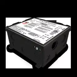
MOUNTING YOUR F50-ATS:
The Furrion ATS is best mounted indoors or in a location sheltered from outdoor elements.
The selected area must be free from the possibility of contaminates and away from water
Do not mount the ATS in a engine compartment.
The ATS mounting location must be accessible after installation is complete to facilitate
future servicing, if possible mount the ATS close to power cord Point of entry or generator
output.
Typical examples of mounting locations are:
Inside seat or bed compartments
Above or behind cabinets’
To mount the ATS box the 4 screw lugs on the outside of the box can be used to secure,
the ATS box also has an alternative 4 screw holes inside the box which can also be used.
Punch out 3 of the large diameter cable strain holes on the side of the box in the
directions which the cables will be fed from using a blunt object. Ensure to remove all
plastic pieces of the punch out cable strain holes by rotating the ATS box upside down.
Hold the transfer switch to the desired position and using 4 self-tapping screws secure
the transfer switch box. Ensure the switch is securely mounted so it cannot move or vibrate.
Once the ATS is securely mounted then screw in the 3 cable strains into the punch out holes
s
e
.
.NOIRRUF C MO
5
Loading ...
Loading ...
Loading ...