MODEL 665RP
Page 1
HEATER / FAN / LIGHT
READ AND SAVE THESE INSTRUCTIONS
To register this product, visit:
www.nutone.com
IMPORTANT INSTRUCTIONS
READ ALL INSTRUCTIONS BEFORE INSTALLING
OR USING THIS HEATER.
To reduce the risk of fire, electric shock, or injury to persons, observe
the following:
1. Use this unit only in the manner intended by the manufacturer. If you
have questions, contact the manufacturer at the address or tele-
phone number listed in the warranty.
2. Before servicing or cleaning unit, switch power off at service panel
and lock the service disconnecting means to prevent power from
being switched on accidentally. When the service disconnecting
means cannot be locked, securely fasten a prominent warning de-
vice, such as a tag, to the service panel.
3. Installation work and electrical wiring must be done by a qualified
person(s) in accordance with all applicable codes and standards,
including fire-rated construction codes and standards.
4. When cutting or drilling into wall or ceiling, do not damage electrical
wiring and other hidden utilities.
5. This heater is hot when in use. To avoid burns, do not let bare skin
touch hot surfaces. Keep combustible materials, such as furniture,
pillows, bedding, papers, clothes, etc. and curtains at least 3 feet
(0.9 m) from the front of the heater.
6. Extreme caution is necessary when any heater is used by or near
children or invalids and whenever the heater is left operating and
unattended.
7. Do not operate any heater after it malfunctions. Disconnect power at
service panel and have heater inspected by a reputable electrician
before reusing.
8. Do not use outdoors.
9. To disconnect heater, turn controls to off, and turn off power to heat-
er circuit at main disconnect panel (or operate internal disconnect
switch, if provided).
10. Do not insert or allow foreign objects to enter any ventilation or ex-
haust opening, as this may cause an electric shock or fire, or dam-
age the heater.
11. To prevent a possible fire, do not block air intakes or exhaust in any
manner.
12. A heater has hot and arcing or sparking parts inside. Do not use it
in areas where gasoline, paint, or flammable vapors or liquids are
used or stored.
13. Use this heater only as described in this manual. Any other use not
recommended by the manufacturer may cause fire, electric shock,
or injury to persons.
14. This product must be grounded.
15. Do not install heater in a tub or shower enclosure.
16. This product is designed for ceiling installation only. This product
is designed for installation in ceilings up to a12/12 pitch. Ductwork
must point up. DO NOT MOUNT THIS PRODUCT IN A WALL.
17. Install heater at least 12 inches from floor or any adjacent wall.
18. Do not connect heater to dimmer switch or speed control.
19. Provide a separate 20 AMP circuit. Use 12 GA. power cable of type
which meets code. Use supply wiring rated for at least 90
O
C.
20. For greatest efficiency, install heater so heat is directed toward tub
or shower area. Avoid directing toward walls or windows.
SAVE THESE INSTRUCTIONS
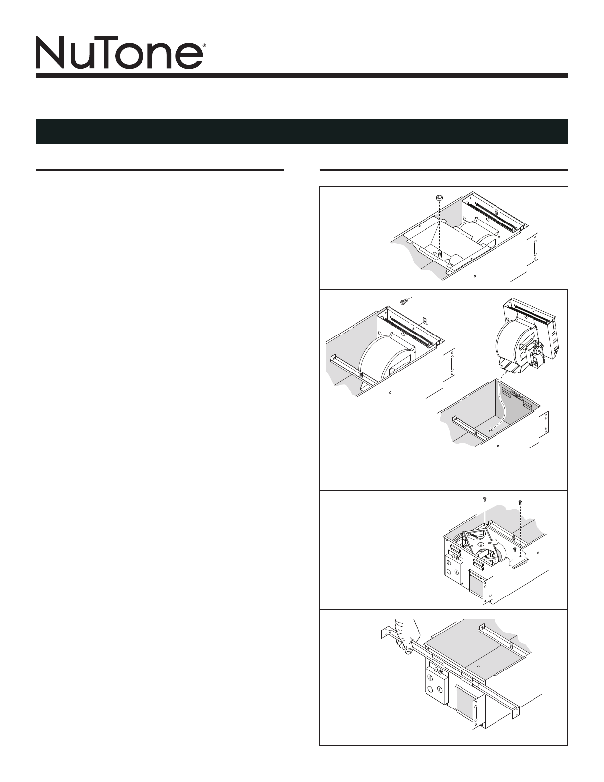
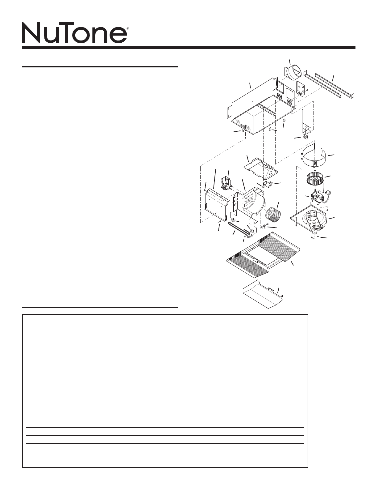
PREPARATION
1. Remove the lamp
holder assembly.
2. Remove the heater
assembly retaining
screw.
3. Rotate heater assembly
and lift it up and out of the
housing.
4. Remove fan assembly
retaining screws. Lift
fan assembly out of the
housing.
5. Slide the 4 hanger
bars into the slots
on each end of the
housing - 2 hanger
bars per side.
MODEL 665RP
Page 2
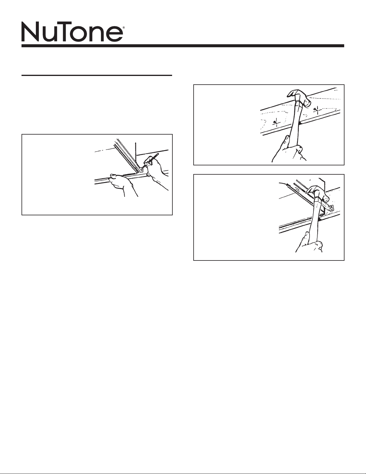
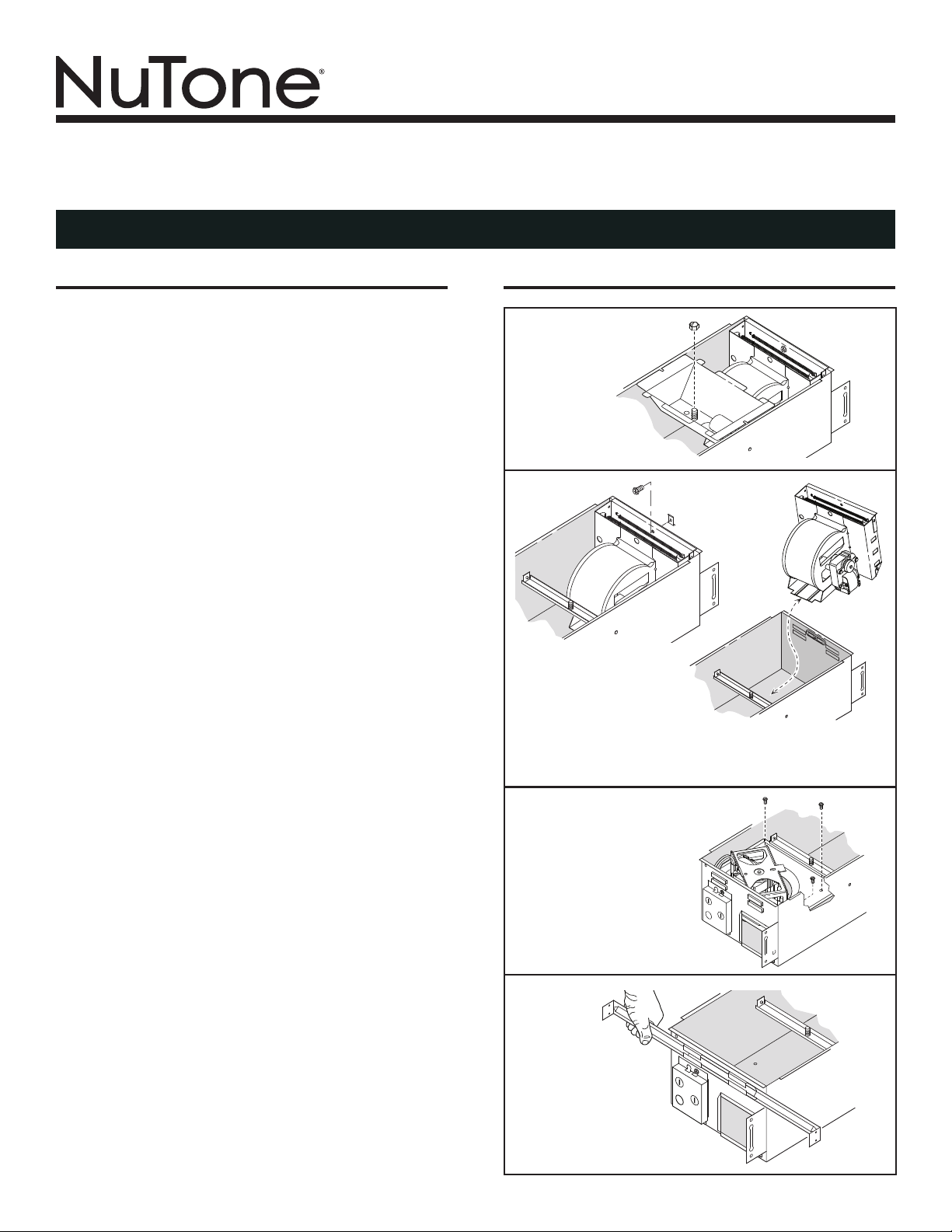
For best results, choose a
location which allows fan to
be vented outside with the
shortest possible duct run
and the fewest number of
elbows.
1. Position unit between
joists and extend mount-
ing brackets. Position
brackets such that the
bottom edge of housing will be flush with finished ceiling.
Mark the top of keyhole slot on all four mounting brackets.
INSTALLATION
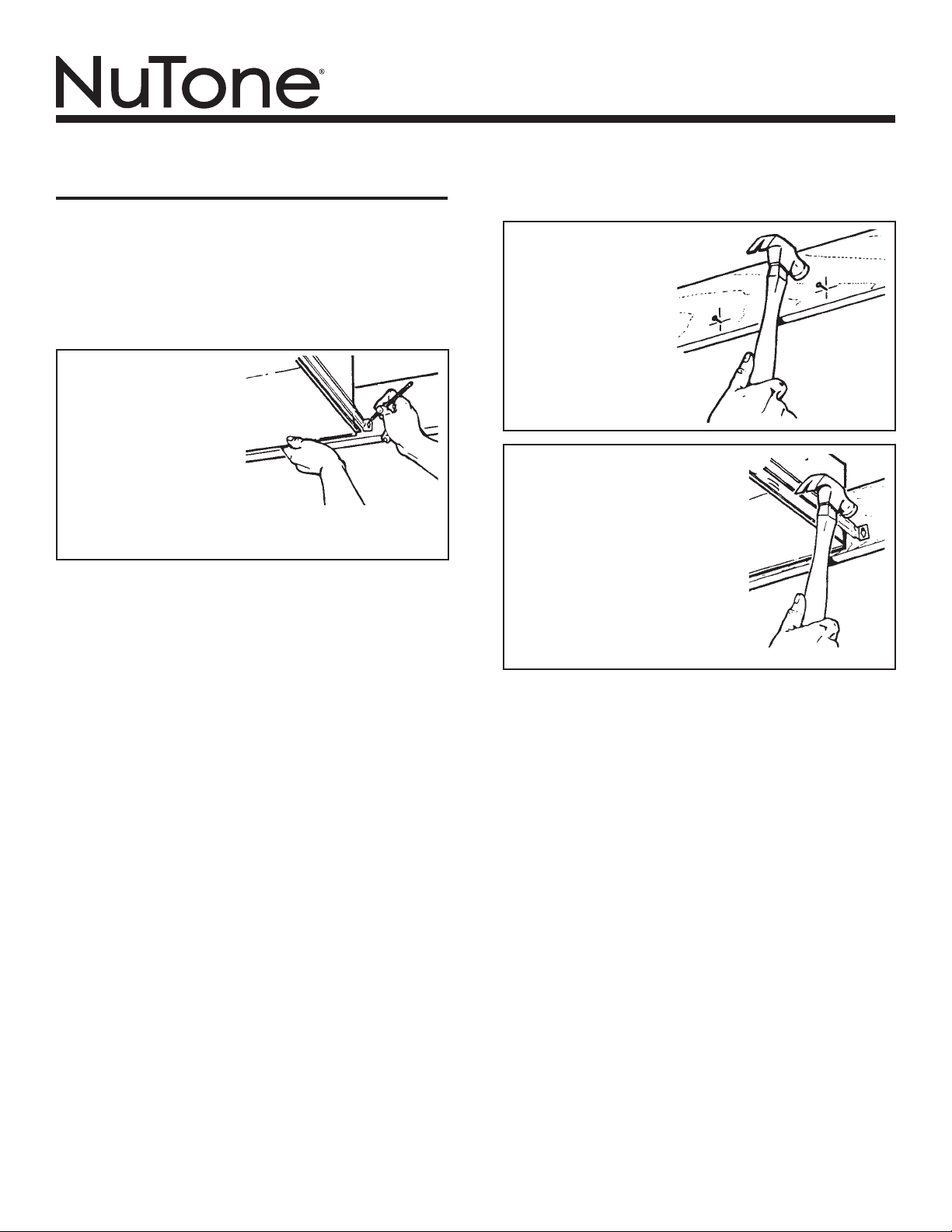
2. Remove unit tem-
porarily, and pound
nails partially into
joists at all four
marked locations.
3. Hang unit from nails and
check if unit will be flush with
finished ceiling. Pound nails
tight. For wide joist centers:
A #8 x 3/8 self-tapping screw
can be used to join extended
brackets together and cre-
ate a rigid mount. To ensure
a noise-free mount, crimp
the bracket channels tightly
around mounting brackets.
WARNING: To reduce the risk of fire, do not store or use
gasoline or other flammable vapors and liquids in the vicin-
ity of the heater.
CAUTION: High temperature, risk of fire, keep electrical cords,
drapery, furnishings, and other combustibles at least 3 feet
(0.9 m) from the front of the heater and away from the side
and rear.

MODEL 665RP
Page 3
RED
BLACK
120 VAC LINE IN
HEAT
VENT
LIGHT
3 GROUND
WIRES
3 GROUND WIRES
A
B
C
LIGHT
VENT
HEAT
BLUE
3 WHITE WIRES
BLACK
RED
2 WHITE
WIRES
BLACK
3 WHITE WIRES
B
C
A
4. Use a flat-bladed
screwdriver
to remove the
proper electrical
knockouts.
5. Connect
electrical
wiring as
shown.
6. Replace the fan assembly removed in Step 4, under “PRE-
PARE THE UNIT” on Page 2. Plug fan assembly into recep-
tacle (C) on the the side of the wiring cover. Direct wires away
from blower inlets.
7. Replace the heater assembly removed in Steps 2, 3, under
“PREPARE THE UNIT” on Page 2. Plug heater assembly into
receptacle (A). Direct wires away from blower inlets.
If the switch has not been wired properly and wires need to
be moved:
1. Each wire opening has a release slot.
2. Push a small nail or screwdriver into release slot while
gently removing wire.
3. DO NOT pull any wire out of the switch without using
the release slot. The switch may be damaged.
WIRE OPENING
RELEASE SLOT
8. Install grille and
light reflector.
Plug light into
receptacle (B).
Tighten acorn
nut securely.
Be careful not
to overtighten
nut and deform
reflector.
Install a 100 Watt
(maximum) light
bulb.
9. Install light
lens. Gently
squeeze tabs
on lens and
insert them
into the slots
in the grille.
Installation work and electrical wiring must be done by a quali-
fied person(s) in accordance with all applicable codes and stan-
dards, including fire-rated construction codes and standards.

MODEL 665RP
Page 4
OPERATION
Before using heater, make sure heater has been properly installed
according to installation steps beginning with the "PREPARATION"
section on page 1.
MODEL 665RP
Page 5
MAINTENANCE
The following maintenance and cleaning tasks can be performed
by the user. All other servicing must be performed by an autho-
rized technician If you have any questions, please consult with
our customer service department at: 800-558-1711.
TO REPLACE BULB
Remove lens by gently depressing sides and pull down. Use bulb
rated up to 100 watts only.
LUBRICATION
The heater is permanently lubricated and never needs oiling or
disassembly.
CLEANING
Clean heater once a month as follows:
1. Turn off power at service panel.
2. Make sure heating element is cool.
3. Use a soft brush attachment to gently vacuum grille openings
or wipe grille clean with a soft cloth.
4. Restore power.
CAUTION: METAL AND ELECTRICAL PARTS SHOULD NEVER
BE IMMERSED IN WATER.
MODEL 665RP
Page 6
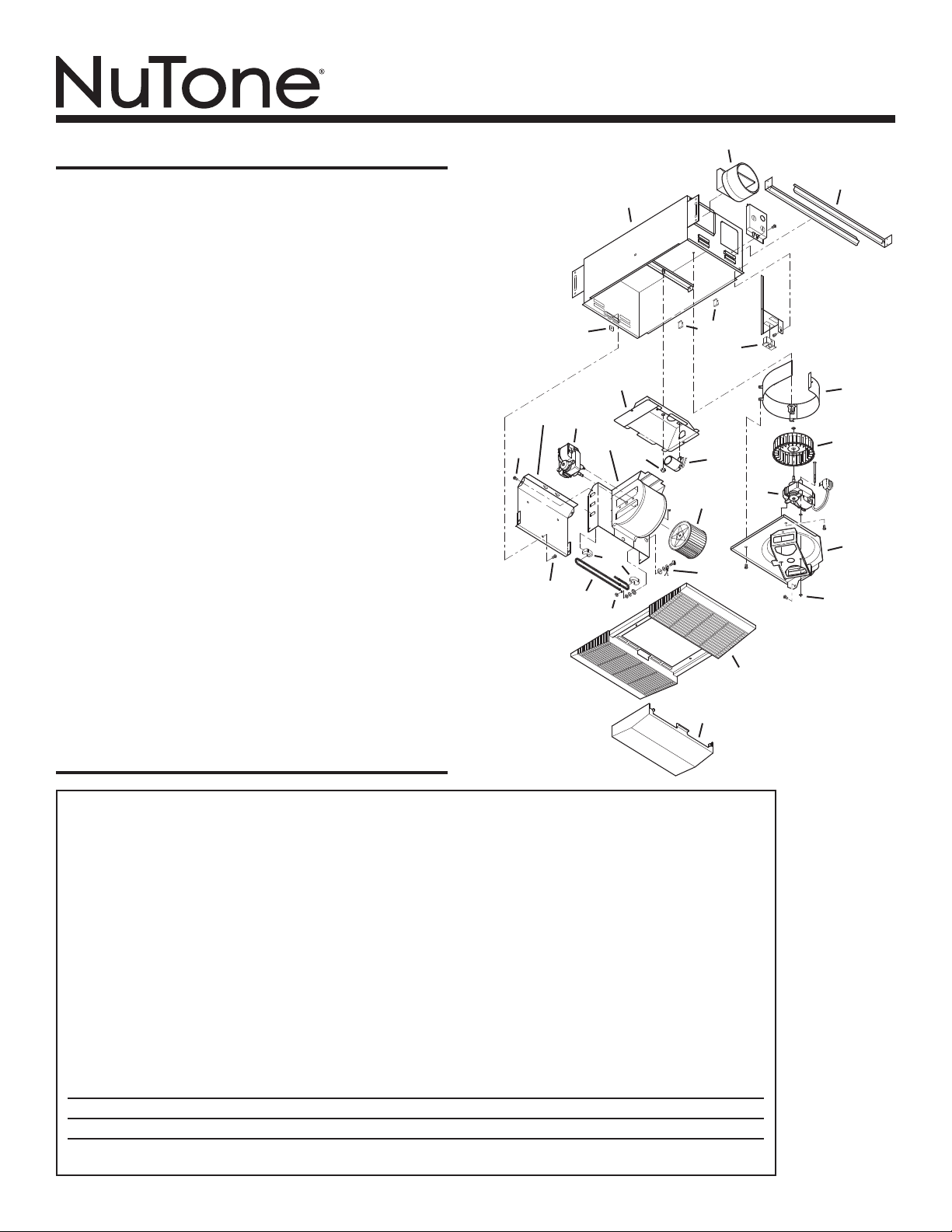
SERVICE PARTS
KEY NO. PART NO. DESCRIPTION
1 97017451 Housing
2 101183000 Damper / Duct Connector
3 44388000 Mounting Bracket (4 Req.)
4 99270981 Receptacle, White
99270982 Receptacle, Black
99270489 Receptacle, Red
5 82403000 Fan Blower Wheel
6 99080592 Fan Motor
7 97017080 Fan Motor Plate Assembly
8 99260428 Nut (4 Req.)
9 89852000 Grille Assembly (includes Key No. 13)
10 98010306 Light Reflector
11 97005316 Acorn Nut
12 99770112 Light Socket
13 53740000 Light Lens
14 97005058 Bolt Assembly
15 99020134 Heater Blower Wheel
16 99150576 #8 x 3/8 Sheet Metal Screw (5 Req.)
17 93260457 #10 - 32 Nut (7 Req.)
(2 included in Key No. 16)
18 99270107 Heater Hooks (5 Req.)
19 98010295 Heater Scroll Cover
20 97017070 Heater Scroll Housing
21 99080593 Heater Motor
22 98004514 Heater Element
23 99260512 Tinnerman Nut
24 99420666 Wire Clip (2 Req.)
25 98010286 Exhaust Fan Scroll Band
1
2
3
4
5
6
7
8
9
10
11
12
13
14
15
16
17
18
16
19
20
21
22
WARRANTY
99045036A
23
24
25
One Year Limited Warranty
WARRANTY OWNER: Broan-NuTone warrants to the original consumer purchaser of its products that such products will be free from defects
in materials or workmanship for a period of one (1) year from the date of original purchase. THERE ARE NO OTHER WARRANTIES, EXPRESS
OR IMPLIED, INCLUDING, BUT NOT LIMITED TO, IMPLIED WARRANTIES OF MERCHANTABILITY OR FITNESS FOR A PARTICULAR PURPOSE.
During this one year period, Broan-NuTone will, at its option, repair or replace, without charge, any product or part which is found to be defective
under normal use and service. THIS WARRANTY DOES NOT EXTEND TO FLUORESCENT LAMP STARTERS OR TUBES, FILTERS, DUCT, ROOF
CAPS, WALL CAPS AND OTHER ACCESSORIES FOR DUCTING. This warranty does not cover (a) normal maintenance and service or (b) any
products or parts which have been subject to misuse, negligence, accident, improper maintenance or repair (other than by Broan-NuTone), faulty
installation or installation contrary to recommended installation instructions.
The duration of any implied warranty is limited to the one year period as specified for the express warranty. Some states do not allow limitation
on how long an implied warranty lasts, so the above limitation may not apply to you.
BROAN-NUTONE’S OBLIGATION TO REPAIR OR REPLACE, AT BROAN-NUTONE’S OPTION, SHALL BE THE PURCHASER’S SOLE AND EXCLUSIVE
REMEDY UNDER THIS WARRANTY. BROAN-NUTONE SHALL NOT BE LIABLE FOR INCIDENTAL, CONSEQUENTIAL OR SPECIAL DAMAGES ARIS-
ING OUT OF OR IN CONNECTION WITH PRODUCT USE OR PERFORMANCE. Some states do not allow the exclusion or limitation of incidental
or consequential damages, so the above limitation or exclusion may not apply to you. This warranty gives you specific legal rights, and you may
also have other rights, which vary from state to state. This warranty supersedes all prior warranties.
WARRANTY SERVICE: To qualify for warranty service, you must (a) notify Broan-NuTone at the address or telephone number below, (b) give the
model number and part identification and (c) describe the nature of any defect in the product or part. At the time of requesting warranty service,
you must present evidence of the original purchase date.
Date of Installation
Builder or Installer
Model No. and Product Description
IF YOU NEED ASSISTANCE OR SERVICE - CONTACT:
Broan-NuTone LLC Hartford, Wisconsin www.nutone.com 888-336-3948
Rev. 08/2007
MODELO 665RP
Página 7
CALENTADOR / VENTILADOR / LÁMPARA
LEA Y CONSERVE ESTAS INSTRUCCIONES
Para colocar este
producto, visite:
www.nutone.com
INSTRUCCIONES IMPORTANTES
LEA TODAS LAS INSTRUCCIONES ANTES DE
INSTALAR O USAR ESTE CALENTADOR.
Para reducir el riesgo de incendios, descargas eléctricas o lesiones personales,
observe las siguientes precauciones:
1. Use la unidad solo de la manera indicada por el fabricante. Si tiene preguntas,
comuníquese con el fabricante a la dirección o al número telefónico que se
incluye en la garantía.
2. Antes de dar servicio a la unidad o de limpiarla, interrumpa el suministro eléctrico
en el panel de servicio y bloquee los medios de desconexión del servicio para
evitar que la electricidad se reanude accidentalmente. Cuando no sea posible
bloquear los medios de desconexión del servicio, fije firmemente una señal de
advertencia (como una etiqueta) en un lugar visible del panel de servicio.
3. El trabajo de instalación y el cableado eléctrico deben estar a cargo de personal
capacitado, de acuerdo con todos los códigos y normas correspondientes,
incluidos los códigos y normas de construcción específicos sobre protección
contra incendios.
4. Al cortar o perforar a través de la pared o del cielo raso, tenga cuidado de no
dañar el cableado eléctrico ni otros servicios ocultos.
5. Este calentador se calienta cuando se usa. Para evitar quemaduras, no deje que
la piel desnuda toque las superficies calientes. Mantenga materiales combustibles
como muebles, almohadas, ropa de cama, papeles, ropa, etc., así como las
cortinas, por lo menos a 3 pies (0.9 m) de la parte delantera del calentador.
6. Es necesario tener extremo cuidado cuando se use un calentador cerca de
niños o personas inválidas, y siempre que el calentador se deje funcionando y
sin atención.
7. No haga funcionar ningún calentador después de que presente una falla.
Desconecte la energía eléctrica en el panel de servicio y pida que un electricista
acreditado inspeccione el calentador antes de volverlo a usar.
8. No lo use en exteriores.
9. Para desconectar el calentador, mueva los controles a la posición de apagado
y desconecte la energía eléctrica al circuito del calentador en el panel de
desconexión principal (o active el interruptor de desconexión interna, si existe).
10. No inserte ni permita que objetos extraños entren en la abertura de ventilación
o de escape, pues esto puede ocasionar una descarga eléctrica, un incendio o
daños al calentador.
11. Para prevenir un posible incendio, no bloquee la entrada o salida del aire de
ninguna manera.
12. El calentador tiene piezas calientes y que pueden generar arcos eléctricos o
chispas en el interior. No lo use en áreas donde se use o almacene gasolina,
pintura o vapores o líquidos flamables.
13. Use este calentador solamente como se describe en este manual. Cualquier
otro uso no recomendado por el fabricante puede ocasionar un incendio, una
descarga eléctrica o lesiones a personas.
14. Este producto debe ser conectado a tierra.
15. No instale esta unidad sobre una bañera o ducha.
16. Este producto está diseñado solamente para instalarse en el cielo raso. Este
producto está diseñado para instalarse en cielos rasos con una pendiente de
hasta 12/12. El sistema de conductos debe apuntar hacia arriba. NO MONTE
ESTE PRODUCTO EN LA PARED.
17. Instale el calentador por lo menos 6 pulg. desde el piso o cualquier pared
adyacente.
18. No conecte el calentador a un variador de luz o control de velocidad.
19. Proporcione un circuito por separado de 20 A. Utilice un cable eléctrico calibre
12 de un tipo conforme al código. Utilice un cable eléctrico clasificado para por
lo menos 90
O
C.
20. Para asegurar una mayor eficiencia, instale el calentador de manera que el
calor esté dirigido hacia el área de la bañera o ducha. Evite dirigir el calor hacia
paredes o ventanas.
GUARDE ESTAS INSTRUCCIONES
PREPARACIÓN
1. Saque el conjunto
del portalámpara.
2. Saque el tornillo de
retención del conjunto
del calentador.
3. Gire el conjunto del calentador
y levántalo y sáquelo de la
cubierta.
4. Saque los tornillos de
retención del conjunto del
ventilador. Levante y saque
el conjunto del ventilador
de la cubierta.
5. Deslice las 4 barras
de suspensión en
las ranuras en cada
extremo de la cubierta:
2 barras de suspensión
por lado.
MODELO 665RP
Página 8
Para obtener los mejores
resultados, elija un sitio
que permita descargar el
ventilador hacia el aire libre y
donde se requiera el tramo de
conductos más corto posible y
el menor número de codos.
1. Coloque la unidad entre las
vigas y extienda los soportes
de montaje. Coloque los soportes
de manera que el borde inferior de la cubierta quede al ras
del cielo raso acabado. Marque la parte superior de la ranura tipo
bocallave en los cuatro soportes de montaje.
INSTALACIÓN
2. Quite temporalmente
la unidad y clave
parcialmente los
clavos en las vigas
en los cuatro lugares
marcados.
3. Cuelgue la unidad en los clavos y
compruebe si la unidad quedará al
ras con el cielo raso acabado. Clave
los clavos de manera que queden
bien ajustados. Para centros de vigas
anchas: se puede usar un tornillo
autorroscante #8 x 3/8 para unir entre
sí los soportes extendidos y crear un
montaje rígido. Para lograr un montaje
silencioso, doble los canales del
soporte ajustadamente alrededor de
los soportes de montaje.
ADVERTENCIA: Para reducir el riesgo de incendio, no almacene
ni use gasolina u otros vapores y líquidos flamables en las
cercanías del calentador.
PRECAUCIÓN: Temperatura alta, el riesgo de incendio, mantenga
los cables eléctricos, cortinas, muebles y otros materiales
combustibles por lo menos 3 pies (0,9 m) del frente del calentador
y lejos de la cara y la parte trasera.

MODELO 665RP
Página 9
A
B
C
B
C
A
ROJO
NEGRO
LÍNEA DE ENTRADA
DE 12O VCA
CALOR
VENTILADOR
LÁMPARA
3 CABLES
DE TIERRA
3 CABLES DE TIERRA
LÁMPARA
VENTILADOR
CALOR
AZUL
3 CABLES BLANCOS
NEGRO
ROJO
2 CABLES
BLANCOS
NEGRO
3 CABLES BLANCOS
4. Con un
destornillador
plano, saque las
tapas removibles
apropiadas.
5. Haga las
conexiones
eléctricas
tal como se
muestra.
6. Vuelva a colocar el conjunto del ventilador que se desmontó en el
paso 4 de la sección “PREPARACIÓN DE LA UNIDAD” (pág. 6). En-
chufe el conjunto del ventilador en el tomacorriente (C) que está al
costado de la cubierta de conexión. Encamine los cables alejándo-
los de las entradas del ventilador.
7. Vuelva a colocar el conjunto del calentador que se desmontó en los
pasos 2 y 3 de la sección “PREPARACIÓN DE LA UNIDAD” (pág. 6).
Enchufe el calentador en el tomacorriente (A). Encamine los cables
alejándolos de las entradas del ventilador.
Si el interruptor no está conectado apropiadamente y hay que
cambiar los cables:
1. Cada entrada para cable tiene una ranura de desenganche.
2. Meta un destornillador o clavo pequeño en la ranura de desen-
ganche al tiempo que saca el cable poco a poco.
3. NO jale ningún cable para sacarlo del interruptor, sin utilizar la
ranura de desenganche, porque podría dañar el interruptor.
ENTRADA PARA CABLE
RANURA DE
DESENGANCHE
8. Instale la rejilla y
el reflector de luz.
Enchufe la luz en
el tomacorriente
(B). Apriete bien
la tuerca ciega.
Tenga cuidado
de no apretarla
en exceso porque
podría deformar el
reflector.
Instale una
bombilla de
100 watts (máx.).
9. Instale la lente
de la lámpara.
Con cuidado,
presione las
lengüetas
en la lente e
insértelas en
las ranuras de
la rejilla.
El trabajo de instalación y el cableado eléctrico deben estar a
cargo de personal capacitado, de acuerdo con todos los códi-
gos y normas correspondientes, incluidos los códigos y normas
de construcción especícos sobre protección contra incendios.

MODEL 665RP
Page 10
OPERACIÓN
Antes de usar el calentador, asegúrese de que esté instalado ad-
ecuadamente, de acuerdo con los pasos de instalación indicados
en “PREPARACION” en la página 1.

MODEL 665RP
Page 11
MANTENIMIENTO
El usuario puede realizar las siguientes tareas de mantenimiento
y limpieza. Todos los demás servicios los debe realizar un técnico
autorizado. Si tiene preguntas, consulte a nuestro departamento
de servicio al cliente llamando al: 800-558- 1711.
PARA REEMPLAZAR LA LAMPARA
Quite el lente, presionando suavemente los lados y empuje. Use
una bombilla de una capacidad nominal máxima de 100 vatios.
LUBRICACIÓN
El calentador está permanentemente lubricado y nunca necesi-
tará ponerle aceite ni desarmarlo.
LIMPIEZA
Limpie el calentador una vez al mes tal como sigue:
1. Apague la energía eléctrica en el panel de servicio.
2. Asegúrese de que el elemento de calefacción esté frío.
3. Use un aditamento de cepillo suave para aspirar suavemente
aberturas de la rejilla o limpie la rejilla con un paño suave.
4. Restaure la energía eléctrica.
CUIDADO: LAS PIEZAS METALICAS Y ELECTRICAS NUNCA
SE DEBEN SUMERGIR EN AGUA.
MODELO 665RP
Página 12
PIEZAS DE REPUESTO
CLAVE N.º PIEZA N.º DESCRIPCIÓN
1
2
3
4
5
6
7
8
9
10
11
12
13
14
15
16
17
18
16
19
20
21
22
GARANTÍA
99045036A
23
24
25
1 97017451 Cubierta
2 101183000 Regulador de tiro / conducto
3 44388000 Soporte de montaje (se necesitan 4)
4 99270981 Tomacorriente, blanco
99270982 Tomacorriente, negro
99270489 Tomacorriente, rojo
5 82403000 Disco del ventilador
6 99080592 Motor del ventilador
7 97017080
Conjunto de la placa del motor del ventilador
8 99260428 Tuerca (se necesitan 4)
9 89852000 Conjunto de rejilla (incluyen clave n.º 13)
10 98010306 Reflector de luz
11 97005316 Tuerca ciega
12 99770112 Cubo de la bombilla
13 53740000 Lente de la luz
14 97005058 Montaje de tornillos
15 99020134 Disco del soplador del calentador
16 99150576 Tornillo autorroscante #8 x 3/8
(se necesitan 5)
17 93260457 Tuerca #10 - 32 (se necesitan 7)
(2 se incluyen en la clave n.º 16)
18 99270107 Ganchos del calentador (se necesitan 5)
19 98010295 Cubierta de la espiral del calentador
20 97017070 Carcasa de la espiral del calentador
21 99080593 Motor del calentador
22 98004514 Elemento del calentador
23 99260512 Tuerca Tinnerman
24 99420666 Clip de cable (se necesitan 2)
25 98010286 Banda deslizante de ventilador
Garantia Limitada de un Año
GARANTÍA DEL PROPIETARIO: Broan-NuTone garantiza al comprador consumidor original de sus productos, por el período de un (1) año desde
la fecha original de compra, que tales productos están libres de defectos en material y mano de obra. NO HAY OTRAS GRANTÍAS, EXPRESADOS
O SOBREENTENDIDAS, INCLUYENDO, PERO NO LIMITADAS A, GRANTÍAS NO EXPRESADAS DE MERCHNTIBILIDAD O ADAPTABLES A UN
PROPÓSITO EN PARTICULAR.
Durante este período de un año, Broan-NuTone reparará o reemplazará a su opción y sin costo, cualquier producto o parte que se encuentre defectuoso
bajo condiciones normales de uso y servicio. ESTA GARANTÍA NO CUBRE A LOS ARRANCADORES PARA LÁMPARAS FLUORESCENTES O A LOS
TUBOS FLUORESCENTES, FILTROS, DUCTOS, TAPAS DE TECHO, TAPAS DE PARED Y OTROS ACCESORIOS PARA CANALIZACIÓN. Esta granatía
no cubre (a) Mantenimiento y servicios normales (b) Productos o partes sujetos al mal uso, negligencia, accidente, mantenimiento inadecuado o
reparaciones (port otros ajenos a Broan-NuTone), instalación defectusoa o a una instalación contraria a las instrucciones de instalación recomendadas.
La duración de cualquier garantia no expresada está limitada a un periodo de un año según se especifica en la garantia expresada. Algunos estados
no permiten limitación en cuanto a la duración de una grantia no expresada, por lo que la limitación arriba indicada puede que no se apliqué a Ud.
LA OBLIGACIÓN DE BROAN-NUTONE DE REPARAR O REEMPLAZAR A SU OPCIÓN, SERÁ EL ÚNICO Y EXCLUSIVO RECURSO QUE TENDRÁ EL
COMPRADOR BAJO ESTA GARANTÍA. BROAN-NUTONE NO SERÁ RESPONSABLE POR DAÑOS INCIDENTALES, CONSECUENTES O ESPECIALES
QUE RESULTEN A CONSECUENCIA O SEAN INDEPENDIENTE DEL USO O DESEMPEÑO DEL PRODUCTO. Algunos estados no permiten la exclusión
o limitación de daños incidentals o consecuentes, de modo que la limitación o exclusión arriba indicada pueda que no se aplique a Ud. Esta garantia
le proporciona derechos legales especificos, y Ud.puede tener otros derechos, los cuales varían de estado a estado. Esta garantias reemplaza a
todas las garantías anteriores..
SERVICO DE GARANTÍA: Para tener derecho al servicio de garantía, Ud. debe (a) Notificar a Broan-NuTone a la dirección o el número de teléfono
abajo, (b) indicar el número de modelo y la identifación de la party y (c) describir la naturaleza de cualquier defecto en la producto o parte. Al mo-
mento de solicitor el servicio por la garantía, Ud. debe presentar la evidencia de la fecha original de compra.
Fecha de la instalación
Constructor o instalador
Número de modelo y descripción del producto
SI NECESITA ASISTENCIA O SERIVIVIO - CONTACTO:
Broan-NuTone LLC Hartford, Wisconsin www.nutone.com 888-336-3948 Rev. 08/2007