Loading ...
Loading ...
Loading ...
6
INSTALLATION TIPS
Ideal installation locations include:
Outdoor Unit
S A location which is convenient to installation and not exposed to
strong wind.
S A location which can bear the weight of the outdoor unit and
where the outdoor unit can be mounted in a level position.
S A location which provides appropriate clearances (see Fig. 3).
S Do not install the indoor or outdoor units in a location with
special environmental conditions. For those applications, contact
your Ductless representative.
OUTDOOR UNIT INSTALLATION
1. Use a rigid base to support the unit in a level position.
2. Locate the outdoor unit and connect the piping and wiring.
CAUTION
!
EQUIPMENT DAMAGE HAZARD
Failure to follow this caution may result in equipment damage
or improper operation.
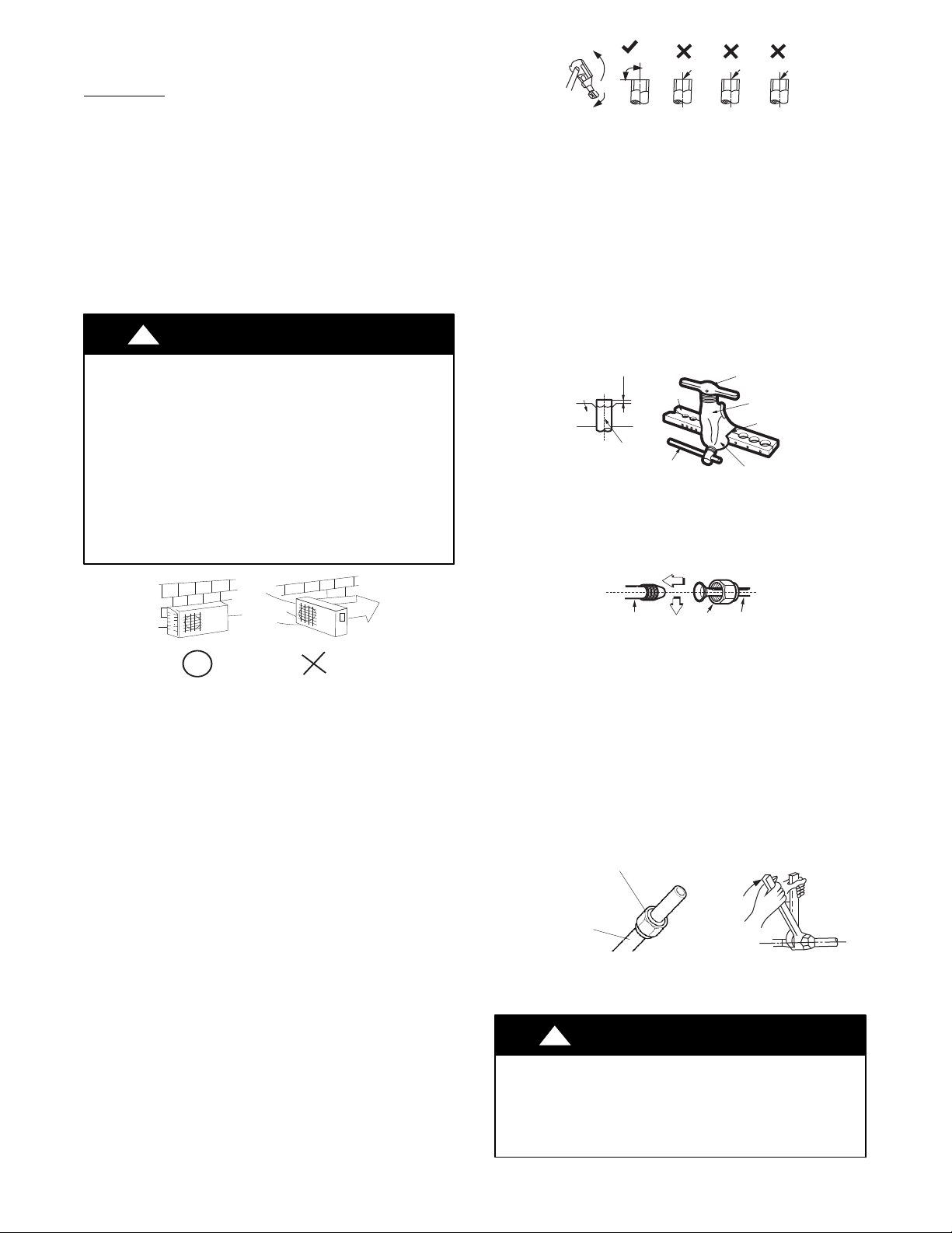
In regions with snowfall and cold temperatures, avoid
installing the outdoor unit in areas where it can be covered by
snow. If the outdoor unit is installed in areas where heavy
snow is expected, a field supplied ice or snow stand and/or
field supplied−installed wind baffle should be installed to
protect the unit from snow accumulation and/or blocked air
intake. Blocking the air intake may result in reduced airflow,
significantly reduced performance and damage to the
equipment.
Strong
wind
A07350
Fig. 4 - High Wind Installation
MAKE REFRIGERANT PIPING CONNECTIONS
(OUTDOOR UNIT)
IMPORTANT: Use refrigeration grade tubing ONLY. No other
type of tubing may be used. Use of other types of tubing will
void the manufacturer’s warranty.
Do not open the service valves or remove protective caps from
tubing ends until all the connections are made.
Bend tubing with bending tools to avoid kinks and flat spots.
Keep the tubing free of dirt, sand, moisture, and other
contaminants
to avoid damaging the refrigerant system.
Avoid sags in the suction line to prevent the formation of oil traps.
Insulate each tube with minimum 3/8−in. (10 mm) wall thermal pipe
insulation.
IMPORTANT: Inserting the tubing into the insulation before
making
the connections will save time and improve installation
quality.
1. Remove the service valve cover, if provided with the unit.
2. Cut the pipe, with a pipe cutter, at 90
_ (see Fig. 5).
3. Remove the service connection, if provided with the unit.
Oblique
DŽ
90
Roughness
Burr
A150767
Fig. 5 - Cut the Pipe
4. Remove all the burrs from the cut cross section of the pipe
avoiding any burrs inside the tubes.
5. Remove the flare nuts attached to the indoor and outdoor
units.
6. Install the correct size flare nut onto the tubing and make a
flare connection. Refer to Table 6 for the flare nut spaces.
Table 6—Flare Nut Spacing
OUTER DIAM. (mm)
A (mm)
Max. Min.
Ø1/4”(6.35) 0.05 (1.3) 0.03(0.7)
Ø3/8”(9.52) 0.06 (1.6) 0.04(1.0)
Ø1/2”(12.7) 0.07 (1.8) 0.04(1.0)
Ø5/8”(15.88) 0.09 (2.2) 0.08(2.0)
Bar
Copper pipe
Clamp handle
Red arrow mark
Cone
Yoke
Handle
Bar
"A"
A150768
Fig. 6 - Flare Nut Spacing
7. Apply a small amount of refrigerant oil to the flare
connection on the tubing.
8. Align the center of the pipes and/or service valve.
Indoor unit tubing Flare nut Piping
A150769
Fig. 7 - Align Pipe Center
9. Connect both the liquid and gas piping to the indoor unit.
10. Tighten the flare nut using a torque wrench as specified in
Table 7.
11. Complete the installation.
Table 7—Tightening Torque
PIPE DIAMETER
INCH (mm)
TIGHTENING TORQUE
Ft-lb N-m
Ø1/4” (6.35) 10 to 13 13.6 to 17.6
Ø3/8” (9.52) 24 to 31 32.5 to 42.0
Ø1/2” (12.7) 37 to 46 50.1 to 62.3
Ø5/8” (15.88) 50 to 60 67.7 to 81.3
Flare nut
Copper tube
A150770
Fig. 8 - Tighten the Flare Nut
CAUTION
!
EQUIPMENT DAMAGE HAZARD
Failure to follow this caution may result in equipment
damage or improper operation.
Excessive torque can break the flare nut depending on
installation conditions.
Loading ...
Loading ...
Loading ...