38MAQ
Outdoor Unit Single Zone Ductless System
Sizes 09 to 30
Installation Instructions
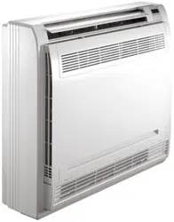
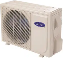
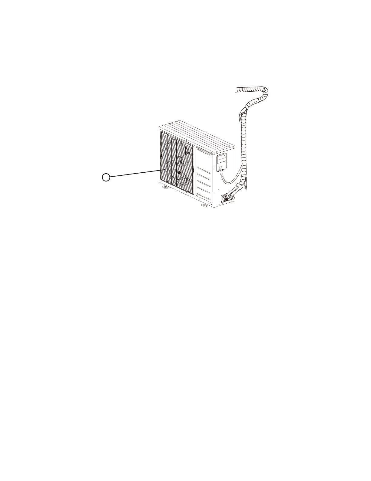
NOTE: The unit image is for illustration purposes only. The
actual model may differ slightly.
NOTE: Read the entire instruction manual before starting the
installation.
TABLE OF CONTENTS
PAGE
SAFETY CONSIDERATIONS 2.........................
PARTS LIST 3.......................................
SYSTEM REQUIREMENTS 4...........................
DIMENSIONS − OUTDOOR 5..........................
CLEARANCES − OUTDOOR 5.........................
INSTALLATION TIPS 6................................
OUTDOOR UNIT INSTALLATION 6.....................
ELECTRICAL DATA 8................................
CONNECTION DIAGRAMS 8..........................
START−UP 10........................................
TROUBLESHOOTING 10..............................
2
SAFETY CONSIDERATIONS
Installing, starting up, and servicing air−conditioning equipment
can be hazardous due to system pressures, electrical components,
and equipment location (roofs, elevated structures, etc.).
Only trained, qualified installers and service mechanics should
install, start−up, and service this equipment.
Untrained personnel can perform basic maintenance functions such
as coil cleaning. All other operations should be performed by
trained service personnel.
When working on the equipment, observe precautions in the
literature and on tags, stickers, and labels attached to the
equipment.
Follow all safety codes. Wear safety glasses and work gloves. Keep
a quenching cloth and a fire extinguisher nearby when brazing.
Use care in handling, rigging, and setting bulky equipment.
Read these instructions thoroughly and follow all warnings or
cautions included in the literature and attached to the unit. Consult
local building codes and National Electrical Code (NEC) for
special requirements. Recognize safety information.
This is the safety−alert symbol
!
!
. When you see this symbol on
the unit and in instructions or manuals, be alert to the potential for
personal injury. Understand these signal words: DANGER,
WARNING, and CAUTION. These words are used with the
safety−alert symbol.
DANGER identifies the most serious hazards which will result in
severe personal injury or death. WARNING signifies hazards
which could result in personal injury or death. CAUTION is used
to identify unsafe practices which may result in minor personal
injury or product and property damage. NOTE is used to highlight
suggestions which will result in enhanced installation, reliability, or
operation.
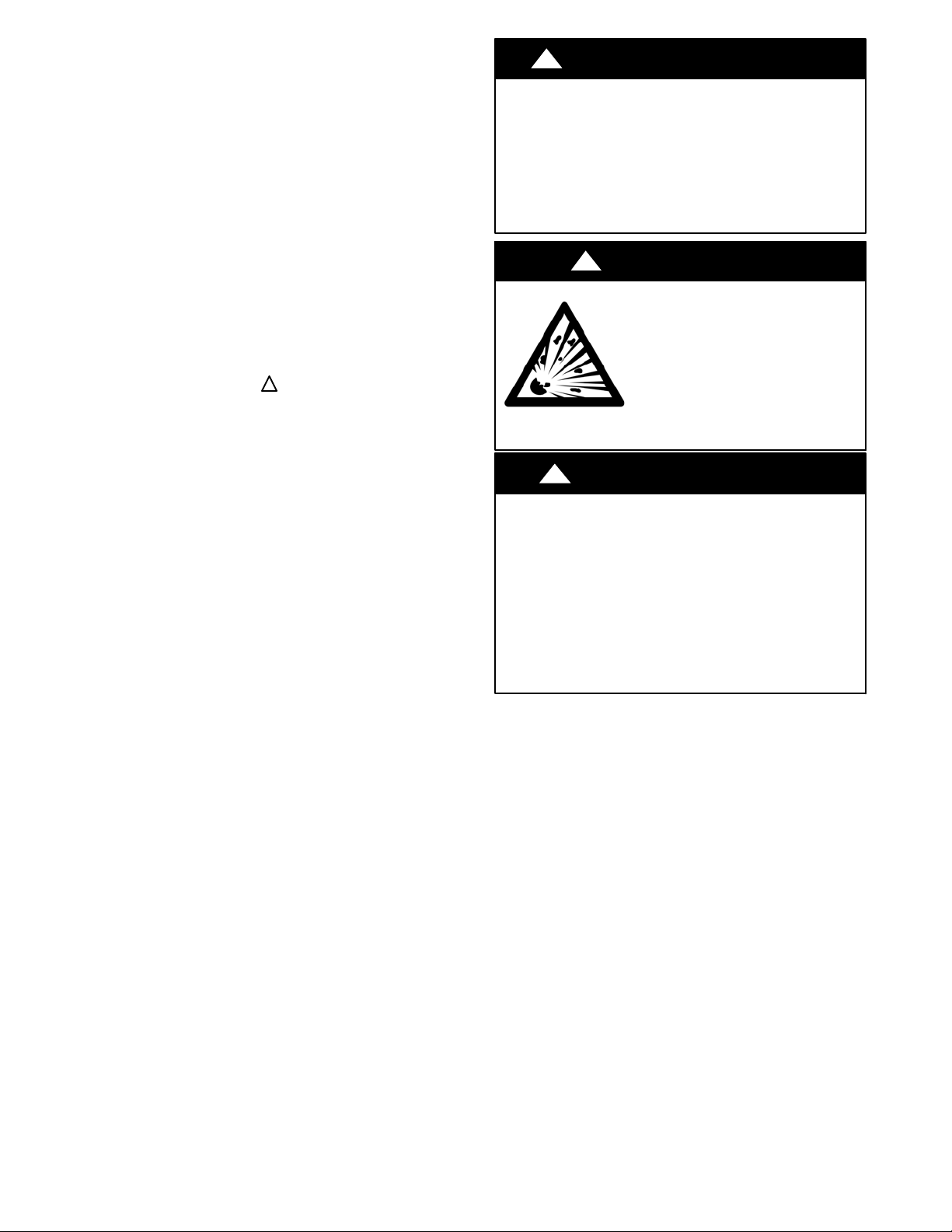
!
WARNING
ELECTRICAL SHOCK HAZARD
Failure to follow this warning could result in personal
injury or death.
Before installing, modifying, or servicing the system,
the main electrical disconnect switch must be in the OFF
position. There may be more than 1 disconnect switch.
Lock out and tag switch with a suitable warning label.
EXPLOSION HAZARD
Failure to follow this warning could
result in death, serious personal injury,
and/or property damage.
Never use air or gases containing
oxygen for leak testing or operating
refrigerant compressors. Pressurized
mixtures of air or gases containing
oxygen can lead to an explosion.
!
WARNING
CAUTION
!
EQUIPMENT DAMAGE HAZARD
Failure to follow this caution may result in equipment
damage or improper operation.
Do not bury more than 36 in. (914 mm) of refrigerant pipe
in the ground. If any section of pipe is buried, there must be
a 6 in. (152 mm) vertical rise to the valve connections on
the outdoor units. If more than the recommended length is
buried, refrigerant may migrate to the cooler buried section
during extended periods of a system shutdown. This causes
refrigerant slugging and could possibly damage the
compressor at start−up.
3
PARTS LIST
Table 1—Parts List
PART No. PART NAME Qty.
1 Outdoor Unit 1
- Literature package including installation instructions and warranty 1
- Grommet to help secure the outdoor unit (helps reduce vibration during unit operation) 4
- Clear Hose 6.5 ft. (2m) 1
■ Outdoor
1
A150766
Fig. 1 - Parts List
NOTE:
− If the outdoor unit is higher than the indoor unit, prevent rain from flowing into the indoor unit along the connection pipe by making
a downward arc in the connection pipe before it enters the wall to the indoor unit. This ensures that rain will drip from the
connection pipe before it enters the wall.
− Piping and the interconnecting wiring are field supplied.
− Figure 1 is only a sketch. Different models may be slightly different.
Table 2 lists the units covered in this document.
Table 2—Unit Sizes
SYSTEM TONS kBTUh VOLTAGE - PHASE OUTDOOR MODEL
0.75 9,000 115-1 38MAQB09---1
1.00 12,000 115-1 38MAQB12---1
0.75 9,000 208/230-1 38MAQB09---3
1.00 12,000 208/230-1 38MAQB12---3
1.50 18,000 208/230-1 38MAQB18---3
2.00 24,000 208/230-1 38MAQB24---3
2.50 30,000 208/230-1 38MAQB30---3
4
SYSTEM REQUIREMENTS
Allow sufficient space for airflow and service of the unit. See Fig. 3 for the required minimum distances between the unit, walls or ceilings.
Piping
IMPORTANT: Both refrigerant lines must be insulated separately.
Table 3 contains piping information for the product covered within this document.
Table 3—Piping and Refrigerant Information
SYSTEM SIZE
9K 12K 9K 12K 18K 24K 30K
(115V) (115V) (208-230V) (208-230 V) (208-230 V) (208-230 V) (208-230 V)
Piping
Min. Piping Length ft (m) 10 (3) 10 (3) 10 (3) 10 (3) 10 (3) 10 (3) 10 (3)
Standard Piping Length ft (m) 25 (7.5) 25 (7.5) 25 (7.5) 25 (7.5) 25 (7.5) 25 (7.5) 25 (7.5)
Max. outdoor-indoor
height difference
ft (m) 32 (10) 32 (10) 32(10) 32(10) 65(20) 65(20) 82(25)
Max. Piping Length with
no additional refrigerant
charge
ft (m) 26 (8) 26(8) 26(8) 26(8) 26(8) 26(8) 26(8)
Max. Piping Length ft (m) 82 (25) 82(25) 82(25) 82(25) 98(30) 98(30) 164 (50)
Additional refrigerant
charge (between
Standard – Max piping
length)
Oz/ft
(g/m)
0.16 (15) 0.16 (15) 0.16 (15) 0.16 (15) 0.16 (15) 0.32 (30) 0.32 (30)
Gas Pipe (size -
connection type)
in
(mm)
3/8 (9.52) 1/2 (12.7) 3/8 (9.52) 1/2 (12.7) 1/2 (12.7) 5/8 (16) 5/8 (16)
Liquid Pipe (size -
connection type)
in 1/4 in 1/4 in 1/4 in 1/4 in 1/4 in 3/8 in 3/8 in
(mm) 6.35 6.35 6.35 6.35 6.35 9.52 9.52
Refrigerant
Refrigerant Type R410A R410A R410A R410A R410A R410A R410A
Charge Amount
Lbs
(kg)
2.76
(1.25)
2.76
(1.25)
2.76
(1.25)
2.76
(1.25)
4.19
(1.90)
5.18
(2.35)
6.62
(3.00)
IMPORTANT: All outdoor units have an electronic expansion
valve which manages the refrigerant flow of the fan coil connected.
Wiring
All wires must be sized per NEC (National Electrical Code) or
CEC (Canadian Electrical Code) and local codes. Use the Electrical
Data table MCA (minimum circuit amps) and MOCP (maximum
over current protection) to correctly size the wires and the
disconnect fuse or breakers respectively.
Per the caution note, only stranded copper conductors with a 600
volt rating and double insulated copper wire must be used. The use
of BX cable is not recommended.
Recommended Connection Method for Power and
Communication Wiring − Power and Communication Wiring:
The main power is supplied to the outdoor unit. The field supplied
14/3 power/communication wiring from the outdoor unit to the
indoor unit consists of four (4) wires and provides the power for
the indoor unit. Two wires are high voltage AC power, one is
communication wiring and the other is a ground wire.
Recommended Connection Method for Power and
Communication Wiring (To minimize communication wiring
interference) Power Wiring:
The main power is supplied to the outdoor unit. The field supplied
power wiring from the outdoor unit to the indoor unit consists of
three (3) wires and provides the power for the indoor unit. Two
wires are high voltage AC power and one is a ground wire.
To minimize voltage drop, the factory recommended wire size is
14/2 stranded with a ground.
Communication Wiring:
A separate shielded stranded copper conductor only, with a 600
volt rating and double insulated copper wire, must be used as the
communication wire from the outdoor unit to the indoor unit.
Please use a separate shielded 16GA stranded control wire.
CAUTION
!
EQUIPMENT DAMAGE HAZARD
Failure to follow this caution may result in equipment
damage or improper operation.
S Wires should be sized based on NEC and local codes.
S Use copper conductors only with a minimum 600 volt
rating and double insulated copper wire.
5
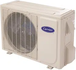
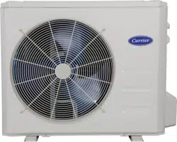
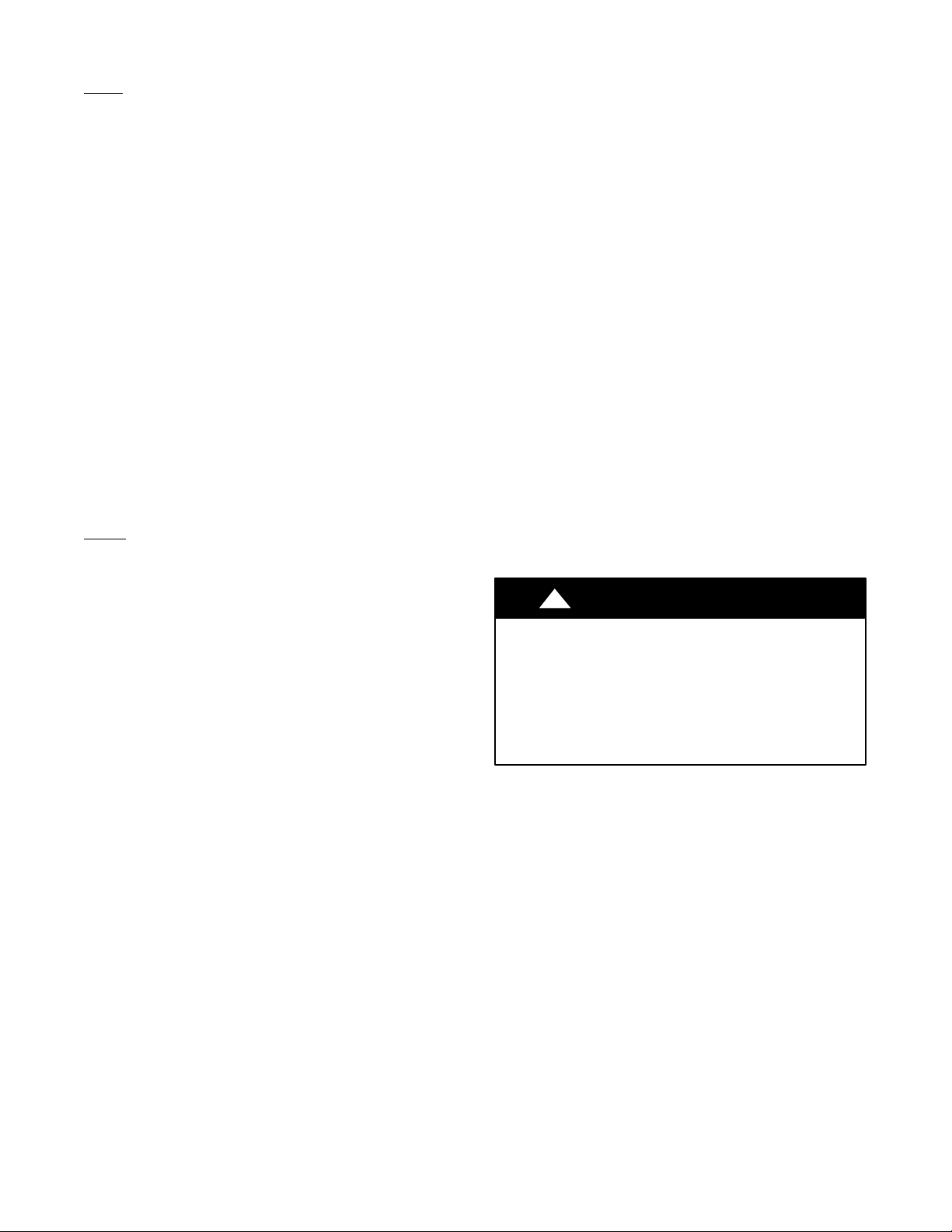
DIMENSIONS − OUTDOOR
A150731
Fig. 2 - Outdoor Unit
Table 4—Unit Sizes
Model Width in (mm) Depth in (mm) Height in (mm) L1 in (mm) L2 in (mm)
Operating
Weight lb (kg)
9K/12K 32.0 (810) 12.2 (310) 22.0 (558) 20.9 (530) 11.4 (290) 82.5 (37.4)
18K 32.3 (845) 12.6 (320) 27.6 (700) 22.1 (560) 13.2 (335) 102.5 (46.5)
24K 37.2 (945) 15.6 (395) 31.9 (810) 25.1 (640) 15.9 (405) 137.6 (62.4)
30K 37.2 (945) 15.6 (395) 31.9 (810) 25.1 (640) 15.9 (405) 157.6 (71.5)
CLEARANCES − OUTDOOR
A
D
B
Air-outlet
Air-inlet
C
E
A07894
Fig. 3 - Outdoor Unit Clearance
Table 5—Outdoor Unit Clearance Dimensions
UNIT
MINIMUM VALUE
in. (mm)
A 24 (610)
B 24 (610)
C 24 (610)
D 4 (101)
E 4 (101)
6
INSTALLATION TIPS
Ideal installation locations include:
Outdoor Unit
S A location which is convenient to installation and not exposed to
strong wind.
S A location which can bear the weight of the outdoor unit and
where the outdoor unit can be mounted in a level position.
S A location which provides appropriate clearances (see Fig. 3).
S Do not install the indoor or outdoor units in a location with
special environmental conditions. For those applications, contact
your Ductless representative.
OUTDOOR UNIT INSTALLATION
1. Use a rigid base to support the unit in a level position.
2. Locate the outdoor unit and connect the piping and wiring.
CAUTION
!
EQUIPMENT DAMAGE HAZARD
Failure to follow this caution may result in equipment damage
or improper operation.
In regions with snowfall and cold temperatures, avoid
installing the outdoor unit in areas where it can be covered by
snow. If the outdoor unit is installed in areas where heavy
snow is expected, a field supplied ice or snow stand and/or
field supplied−installed wind baffle should be installed to
protect the unit from snow accumulation and/or blocked air
intake. Blocking the air intake may result in reduced airflow,
significantly reduced performance and damage to the
equipment.
Strong
wind
A07350
Fig. 4 - High Wind Installation
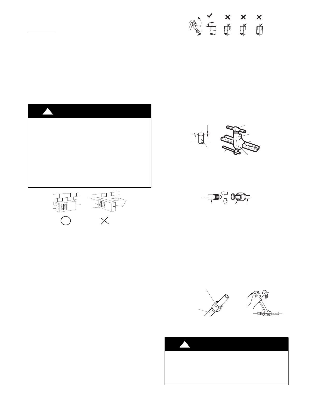
MAKE REFRIGERANT PIPING CONNECTIONS
(OUTDOOR UNIT)
IMPORTANT: Use refrigeration grade tubing ONLY. No other
type of tubing may be used. Use of other types of tubing will
void the manufacturer’s warranty.
Do not open the service valves or remove protective caps from
tubing ends until all the connections are made.
Bend tubing with bending tools to avoid kinks and flat spots.
Keep the tubing free of dirt, sand, moisture, and other
contaminants
to avoid damaging the refrigerant system.
Avoid sags in the suction line to prevent the formation of oil traps.
Insulate each tube with minimum 3/8−in. (10 mm) wall thermal pipe
insulation.
IMPORTANT: Inserting the tubing into the insulation before
making
the connections will save time and improve installation
quality.
1. Remove the service valve cover, if provided with the unit.
2. Cut the pipe, with a pipe cutter, at 90
_ (see Fig. 5).
3. Remove the service connection, if provided with the unit.
Oblique
DŽ
90
Roughness
Burr
A150767
Fig. 5 - Cut the Pipe
4. Remove all the burrs from the cut cross section of the pipe
avoiding any burrs inside the tubes.
5. Remove the flare nuts attached to the indoor and outdoor
units.
6. Install the correct size flare nut onto the tubing and make a
flare connection. Refer to Table 6 for the flare nut spaces.
Table 6—Flare Nut Spacing
OUTER DIAM. (mm)
A (mm)
Max. Min.
Ø1/4”(6.35) 0.05 (1.3) 0.03(0.7)
Ø3/8”(9.52) 0.06 (1.6) 0.04(1.0)
Ø1/2”(12.7) 0.07 (1.8) 0.04(1.0)
Ø5/8”(15.88) 0.09 (2.2) 0.08(2.0)
Bar
Copper pipe
Clamp handle
Red arrow mark
Cone
Yoke
Handle
Bar
"A"
A150768
Fig. 6 - Flare Nut Spacing
7. Apply a small amount of refrigerant oil to the flare
connection on the tubing.
8. Align the center of the pipes and/or service valve.
Indoor unit tubing Flare nut Piping
A150769
Fig. 7 - Align Pipe Center
9. Connect both the liquid and gas piping to the indoor unit.
10. Tighten the flare nut using a torque wrench as specified in
Table 7.
11. Complete the installation.
Table 7—Tightening Torque
PIPE DIAMETER
INCH (mm)
TIGHTENING TORQUE
Ft-lb N-m
Ø1/4” (6.35) 10 to 13 13.6 to 17.6
Ø3/8” (9.52) 24 to 31 32.5 to 42.0
Ø1/2” (12.7) 37 to 46 50.1 to 62.3
Ø5/8” (15.88) 50 to 60 67.7 to 81.3
Flare nut
Copper tube
A150770
Fig. 8 - Tighten the Flare Nut
CAUTION
!
EQUIPMENT DAMAGE HAZARD
Failure to follow this caution may result in equipment
damage or improper operation.
Excessive torque can break the flare nut depending on
installation conditions.
7
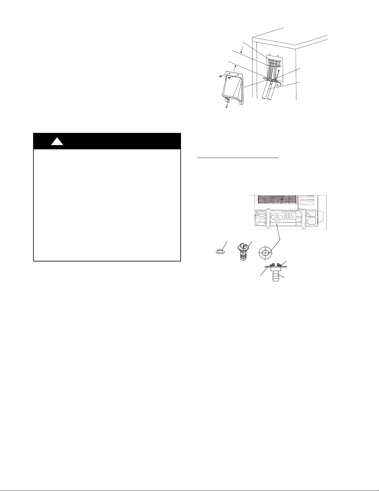
INSTALL ALL POWER AND INTERCONNECTING
WIRING TO OUTDOOR UNITS
1. Mount the outdoor power disconnect.
2. Run the power wiring from the main box to disconnect per
NEC and local codes.
3. Remove the field wiring cover from the unit by loosening
the screws.
4. Remove the caps from the conduit panel.
5. Connect the conduit to the conduit panel (see Fig.9).
6. Properly connect both the power supply and the control
lines to the terminal block per the connection diagram for
the appropriate unit capacity and voltage.
7. Ground the unit in accordance with NEC and local electrical
codes.
8. Use the lock nuts to secure the conduit.
9. Reinstall the field wiring cover.
CAUTION
!
EQUIPMENT DAMAGE HAZARD
Failure to follow this caution may result in equipment
damage or improper operation.
S Be sure to comply with local codes while running wire
from the indoor unit to the outdoor unit.
S Every wire must be connected firmly. Loose wiring may
cause the terminal to overheat or result in a unit
malfunction. A fire hazard may also exist. Therefore, be
sure all wiring is tightly connected.
S No wire should be allowed to touch the refrigerant
tubing, compressor or any moving parts.
S Disconnecting means must be provided and shall be
located within sight and readily accessible from the air
conditioner.
S Connecting the cable with the conduit shall be routed
through a hole in the conduit panel.
G
Over 1.57" (40mm)
Terminal Block
Conduit panel
Conduit
Outdoor unit
A07455
Fig. 9 - Field Wiring
DRAIN CONNECTIONS
Install drains must meet the local sanitation codes.
Install the outdoor unit drain joint
Fit the seal into the drain joint, then insert the drain joint into the
outdoor unit’s base pan hole and then rotate 90
_ to securely
assemble them. Connect the drain joint with an extension drain
hose to avoid condensate from draining off the outdoor unit during
the heating mode.
Seal
Base pan hole
Drain joint
Seal
Base pan
Drain
joint
Fig. 10 - Drain Joint
Images are for illustration purposes only.
8
ELECTRICAL DATA
Table 8—Electrical Data
MAQ OUTDOOR UNIT SIZE 9K 12K 9K 12K 18K 24K 30K
Power
Supply
Volts-PH-Hz 115-1-60 115-1-60 208/230-1-60 208/230-1-60 208/230-1-60 208/230-1-60 208/230-1-60
Max – Min*
Oper. Voltage
126-104 126-104 253-187 253-187 253-187 253-187 253-187
MCA 15 15 15 15 13 15 20
Max Fuse/
CB AMP
20 20 15 15 20 25 30
Compressor
Volts-PH-Hz 115-1-60 115-1-60 208/230-1-60 208/230-1-60 208/230-1-60 208/230-1-60 208/230-1-60
RLA 5.3 5.7 5.3 5.7 7.3 8.8 13.5
Outdoor Fan
Motor
Volts-PH-Hz 115-1-60 115-1-60 208/230-1-60 208/230-1-60 208/230-1-60 208/230-1-60 208/230-1-60
FLA 0.14 0.14 0.42 0.42 0.95 0.47 1.21
Rated HP 0.053 0.053 0.053 0.053 0.067 0.16 0.16
Output 40 40 40 40 50 120 120
*Permissible limits of the voltage range at which the unit will operate satisfactorily.
LEGEND
FLA - Full Load Amps
MCA - Minimum Circuit Amps
RLA - Rated Load Amps
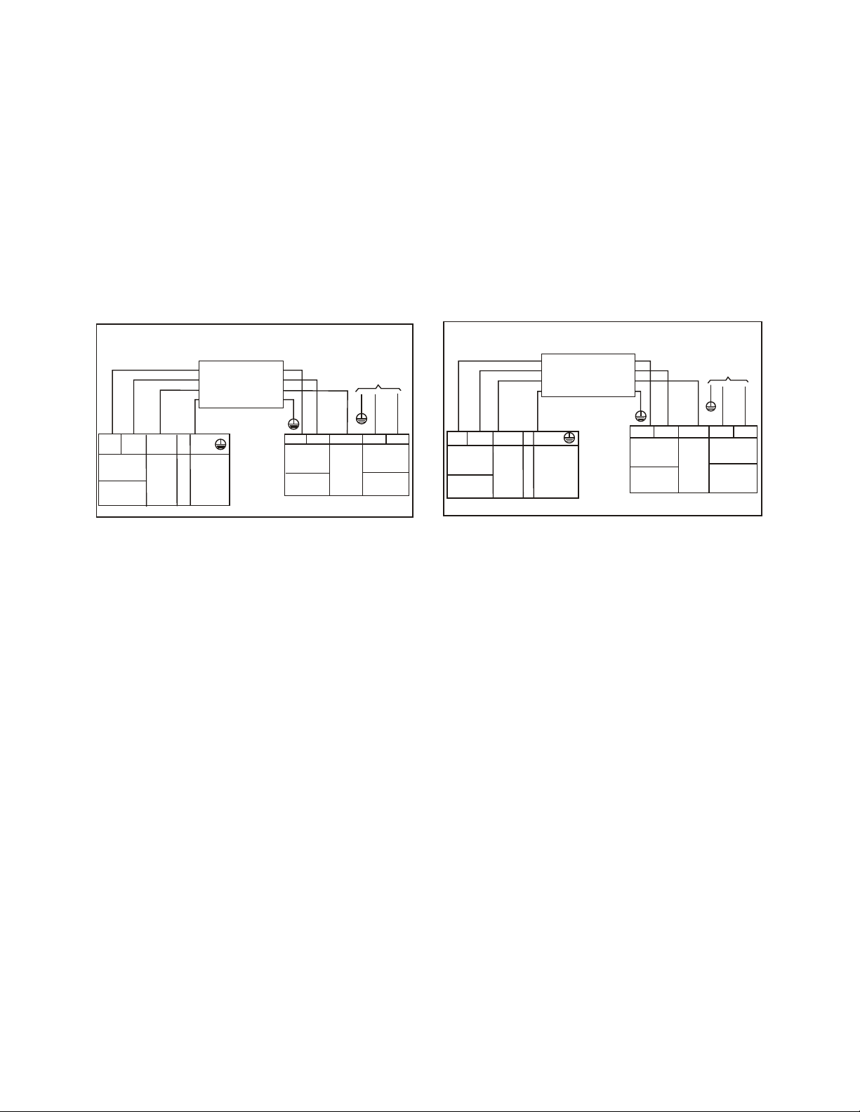
CONNECTION DIAGRAMS
S
L
N
115-1-60
Main
Power Supply
115-1-60
L
N
S
L
N
Power to
Indoor Unit
CONNECTING CABLE
OUTDOOR TO INDOOR
GND
Ground
Indoor
Signal
High
Voltage
115-1-60
115-1-60
FIELD POWER SUPPLY
GND
Indoor
Signal
High
Voltage
Indoor Unit
Power Supply
S
L1 L2
208/230-1-60
Main
Power Supply
L1
L2
S
L1
L2
CONNECTING CABLE
OUTDOOR TO INDOOR
Indoor Unit
Power Supply
208/230-1-60
Indoor
Signal
High
Voltage
GND
Ground
Power to
Indoor Unit
Indoor
Signal
High
Voltage
208/230-1-60
FIELD POWER SUPPLY
GND
208/230-1-60
9K and 12K 115V Indoor Unit 9K and 12K 115V Outdoor Unit 9K to 30K 230V Indoor Unit 9K to 30K 230V Outdoor Unit
Fig. 11 - Connection Diagrams
A14506
Notes:
1. Do not use the thermostat wire for any connection between the indoor and outdoor units.
2. All connections between the indoor and outdoor units must be as shown in Fig. 11. The connections are sensitive to polarity and will result in a fault
code.
9
SYSTEM VACUUM AND CHARGE
UNIT DAMAGE HAZARD
Failure to follow this caution may result in equipment
damage or improper operation.
Never use the system compressor as a vacuum pump.
CAUTION
!
Refrigerant tubes and the indoor coil should be evacuated using the
recommended 500 microns deep vacuum method. The alternate
triple evacuation method may be used if the procedure outlined
below is followed.
NOTE: Always break a vacuum with dry nitrogen.
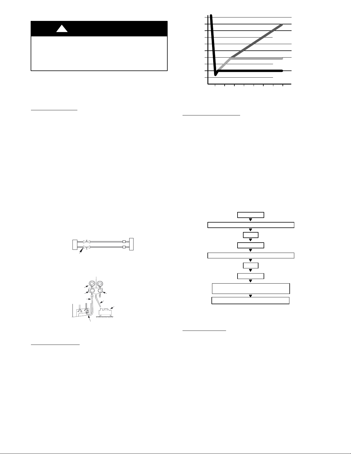
Using Vacuum Pump
1. Completely tighten flare nuts A, B, C, D, connect the
manifold gage charge hose to a charge port of the low side
service valve (see Fig. 12).
2. Connect the charge hose to the vacuum pump.
3. Fully open the low side of the manifold gage (see Fig. 13).
4. Start the vacuum pump.
5. Evacuate using either the deep vacuum or the triple
evacuation method.
6. After the evacuation is complete, fully close the low side of
the manifold gage and stop the vacuum pump operation.
7. The factory charge contained in the outdoor unit is good for
up to 25 ft. (8 m) of line length. For refrigerant lines longer
than 25 ft. (8 m), add refrigerant, up to the allowable length,
as specified in the System Requirements section.
8. Disconnect the charge hose from the charge connection of
the low side service valve.
9. Fully open service valves B and A.
10. Securely tighten the service valves caps.
Outdoor Unit
Indoor Uni
t
Refrigerant
Service Valve
Low Side
High Side
A
B
C
D
A07360
Fig. 12 - Service Valve
Manifold Gage
500 microns
Low side valve
High side valve
Charge hose
Charge hose
Vacuum pump
Low side valve
A07361
Fig. 13 - Manifold
Deep Vacuum Method
The deep vacuum method requires a vacuum pump capable of
pulling a vacuum of 500 microns and a vacuum gage capable of
accurately measuring this vacuum depth. The deep vacuum method
is the best way to assure a system is free of air and liquid water (see
Fig. 14).
500
MINUTES
01234567
1000
1500
LEAK IN
SYSTEM
VACUUM TIGHT
TOO WET
TIGHT
DRY SYSTEM
2000
MICRONS
2500
3000
3500
4000
4500
5000
A95424
Fig. 14 - Deep Vacuum Graph
Triple Evacuation Method
The triple evacuation method should only be used when the
vacuum pump is only capable of pumping down to 28 in. of
mercury vacuum and system does not contain any liquid water.
Refer to Fig. 15 and proceed as follows:
1. Pump the system down to 28 in. of mercury and allow the
pump to continue operating for an additional 15 minutes.
2. Close the service valves and shut off the vacuum pump.
3. Connect a nitrogen cylinder and regulator to the system and
open until the system pressure is 2 psig.
4. Close the service valve and allow the system to stand for 1
hr. During this time, dry nitrogen will be able to diffuse
throughout the system absorbing moisture.
5. Repeat this procedure as indicated in Fig. 15. The system
will then be free of any contaminants and water vapor.
CHECK FOR TIGHT, DRY SYSTEM
(IF IT HOLDS DEEP VACUUM)
EVACUATE
BREAK VACUUM WITH DRY NITROGEN
WAIT
EVACUATE
RELEASE CHARGE INTO SYSTEM
BREAK VACUUM WITH DRY NITROGEN
EVACUATE
WAIT
A95425
Fig. 15 - Triple Evacuation Method
Final Tubing Check
IMPORTANT: Ensure that certain factory tubing on both the
indoor and outdoor unit has not shifted during shipment. Ensure
tubes are not rubbing against each other or any sheet metal. Pay
close attention to the feeder tubes and make sure the wire ties on
the feeder tubes are secure and tight.

10
START−UP
Test Operation
Perform a test operation after completing the gas leak and electrical safety check. See the indoor unit installation instructions and owner’s
manual for additional start up information.
SYSTEM CHECKS
1. Conceal the tubing where possible.
2. Ensure the drain tube slopes downward along its entire length.
3. Ensure all tubing and connections are properly insulated.
4. Fasten the tubes to the outside wall, when possible.
5. Seal the hole through which the cables and tubing pass.
OUTDOOR UNIT
1. Are there unusual noises or vibrations during operation?
Explain the Following Items to the Customer (with the aid of the Owner’s Manual):
1. Explain care and maintenance.
2. Present the installation instructions to the customer.
TROUBLESHOOTING
For ease of service, the systems are equipped with diagnostic code display LEDs on both the indoor and outdoor units. The outdoor
diagnostic display consists of two LEDs (Red and Green) on the outdoor unit board and is limited to very few errors. The indoor diagnostic
display is a combination of flashing LEDs on the display panel or the front of the unit.
There may be a few error codes displayed on the indoor unit that might relate to the outdoor unit’s problems. If possible, always check the
diagnostic codes displayed on the indoor unit first.
The diagnostic codes displayed in the outdoor units are listed in Table 9.
Table 9—Outdoor Unit Diagnostic Guides
GREEN LED RED LED FAILURE MODE
On X Standby, normal
X On Operation, normal
On On High/Low voltage protection on compressor terminal
On ☆ EEPROM error
X ☆ The compressor speed is out of control
☆ On Zero-crossing signal detection error; lack of phase; synchronization error
☆ X IGBT or Module protection
☆ ☆ Communication error
☆ = Flashing, X = Off
For additional diagnostic information, refer to the Service Manual.
Copyright 2016 Carrier Corp. D 7310 W. Morris St. D Indianapolis, IN 46231 . Edition Date: 05/16
Manufacturer reserves the right to change, at any time, specifications and designs without notice and without obligations.
Catalog No: 38MAQ-01SI
Replaces: NEW