FLOOR/CEILING
OWNER’S MANUAL
Models:
Indoor Unit Outdoor Unit
UMAT18HP230V1AF UMAT18HP230V1AO
UMAT24HP230V1AF UMAT24HP230V1AO
UMAT30HP230V1AF UMAT30HP230V1AO
UMAT36HP230V1AF UMAT36HP230V1AO
UMAT42HP230V1AF UMAT42HP230V1AO
UMAT48HP230V1AF UMAT48HP230V1AO

Table of Contents
Introduction . . . . . . . . . . . . . . . . . . . . . . . . . . . . . . . . . . . . . . . . . . . . . . . . . 2
Nomenclature . . . . . . . . . . . . . . . . . . . . . . . . . . . . . . . . . . . . . . . . . . . . . . . 3
Safety Precautions . . . . . . . . . . . . . . . . . . . . . . . . . . . . . . . . . . . . . . . . . . . . 4
System Schematic
. . . . . . . . . . . . . . . . . . . . . . . . . . . . . . . . . . . . . . . . . . . .
5
System Functions . . . . . . . . . . . . . . . . . . . . . . . . . . . . . . . . . . . . . . . . . . 6-8
Operation of Wireless Remote Controller . . . . . . . . . . . . . . . . . . . . . . . 9-14
Care and Cleaning . . . . . . . . . . . . . . . . . . . . . . . . . . . . . . . . . . . . . . . . . . . 15
Troubleshooting . . . . . . . . . . . . . . . . . . . . . . . . . . . . . . . . . . . . . . . . . . 16-17
Diagnostic Codes . . . . . . . . . . . . . . . . . . . . . . . . . . . . . . . . . . . . . . . . . 18-20
Energy Saving Tips . . . . . . . . . . . . . . . . . . . . . . . . . . . . . . . . . . . . . . . . . . . 21
Warranty . . . . . . . . . . . . . . . . . . . . . . . . . . . . . . . . . . . . . . . . . . . . . . . . Back
Thank you for choosing a
Floor/Ceiling
Air Conditioning & Heating System.
You can feel confident in your selection because the same pride in craftsmanship
and engineering knowledge that goes into millions of other Gree installed
products worldwide has gone into your unit.
Please read this owner’s manual carefully before operation and retain it for
future reference.

Superior Design for Superior Performance
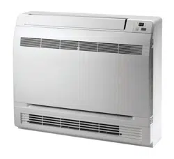
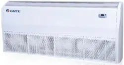
Gree’s Universal Floor/Ceiling indoor unit is designed to be suspended from a
ceiling or mounted low on a wall. The slender and lightweight design is perfect
for restaurants, light commercial applications, or wherever wall space is limited.
Aesthetically pleasing to the eye, the Universal Floor/Ceiling unit is a great fit
beneath windows, in hallways or in any public space requiring discreet, powerful
climate control. The unit is operated by an Infrared Remote Controller or Wired
Tether Controller (sold separately) to allow maximum flexibility in any application.
INTRODUCTION
2
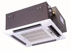
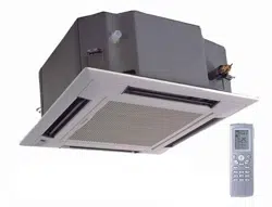
Indoor unit
Outdoor unit
3
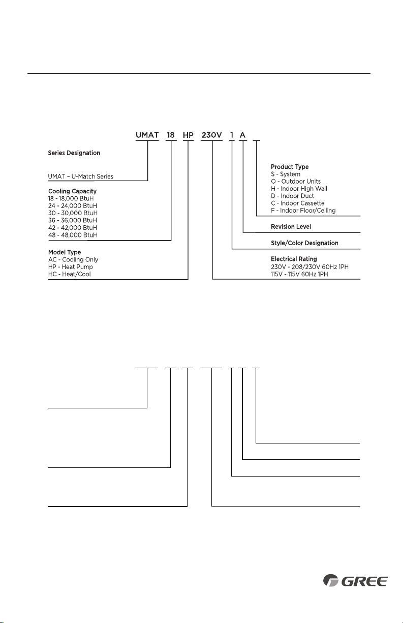
NOMENCLATURE
E
x
a
m
p
l
e
:
U
M
A
T
1
8
H
P
2
3
0
V
1
A
F
F
UMAT 18 1 A O
Series Designation
UMAT – U-Match Series
Product Type
S - System
O - Outdoor Units
H - Indoor High Wall
D - Indoor Duct
C - Indoor Cassette
F - Indoor Floor/Ceiling
Revision Level
Style/Color Designation
Electrical Rating
230V - 208/230V 60Hz 1PH
115V - 115V 60Hz 1PH
HP
230V
Cooling Capacity
18 - 18,000 BtuH
24 - 24,000 BtuH
30 - 30,000 BtuH
36 - 36,000 BtuH
42 - 42,000 BtuH
48 - 48,000 BtuH
Model Type
AC - Cooling Only
HP - Heat Pump
HC - Heat/Cool
Example: UMAT18HP230V1AO
• Disconnect electrical power to the indoor and outdoor units before performing any
maintenance or cleaning.
• Do not attempt to repair the
Gree
system yourself. Incorrect repairs may cause electric
shock or fire. Contact a qualified service technician for all service requirements.
• Keep combustible materials away from the unit.
• Do not put hands or any objects into the air inlets or outlets. This may cause personal
injury or damage the unit.
• When cleaning, be careful not to splash water on the unit. Doing this may cause
electric shock or damage to unit.
• In the event of a failure (burning smell, etc.), immediately disconnect all electrical power
to indoor and outdoor units.
SAFETY PRECAUTIONS
Please read the following before operation.
Recognize safety information. This is the safety-alert symbol. When you see this symbol on
the unit and in instructions or manuals, be alert to the potential for personal injury. Understand
these signal words: DANGER, WARNING, and CAUTION. These words are used with the
safety-alert symbol.
DANGER identifies the most serious hazards which will result in severe personal injury or death.
WARNING signifies hazards which could result in personal injury or death.
CAUTION is used to identify unsafe practices which may result in minor personal injury or
product and property damage.
NOTE is used to highlight suggestions which will result in enhanced installation, reliability, or operation.
NOTE: Your actual air conditioning & heating system and related devices may differ from
the images shown in this manual.
This appliance is not intended for use by children without responsible adult supervision.
Proper care should be taken to ensure safety.
Heat pumps, air conditioners & heating equipment should be installed, started up, and
serviced only by qualified installers and service technicians. Air conditioning, heat pumps
and refrigeration systems are hazardous due to high voltage electrical components, high
refrigerant pressures, and moving parts.
WARNING
WARNING
WARNING
CAUTION
4
5
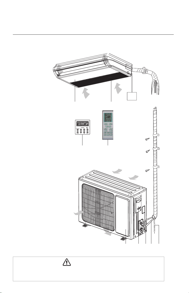
Air inlet
System Schematic
Indoor Unit
System Combonents*
1. Front Cabinet
2. Air Inlet
3. Wired Controller
(sold separately)
4. Remote Controller
5. Drain Pipe
6. Gas Pipe
7. Liquid Pipe
8. Service Cover
9. Front Panel
Outdoor Unit
Air outlet
Air inlet
9
8
3
4
1
2
76 5
The refrigerant pipe, drain pipe and electrical wiring for this unit should be installed by a
qualified HVAC professional only.
CAUTION
Air Outlet
Power
Supply
*
Not all items included in equipment
purchase

SYSTEM FUNCTIONS
WHISPER QUIET
Not only are the Gree systems energy efficient but they are quiet too. Wall mounted units
operate with sound levels starting as low as 37 dB(A).
MODERN APPEARANCE
Designed to be a comfortable fit in virtually any living space. This slim compact cabinet sits
inconspicuously on the wall or ceiling, and blends into most interior designs.
UNIT DISPLAY
Gree wall mounted units have a large easy to read display and indicator lights giving instant
feedback on room setpoint, operating mode and much more. The display can also be turned
off based on your personal preference.
MULTI FAN SPEEDS
Whether operating in either Cooling or Heating mode, the indoor fan can be set to your choice
of three different speeds (Low, Medium or High) to achieve maximum comfort.
TIME GUARD
The U-Match system is equipped with many system safeties to provide safe, reliable operation
and comfort. The Time Guard function prevents rapid cycling of the compressor. The system
has a protective five-minute time delay to restart the compressor after it has turned off.
POWER FAILURE MODE
Power interruptions are no problem for the U-Match system. User selections and system parameters
are stored in non-volatile memory. These parameters are retained during a power failure. When
power is returned, the Floor/Ceiling system will automatically return to the last operating mode.
INTELLIGENT PRE-HEATING
U-Match systems guards against the annoying cool air blown into the room in heating mode.
The system constantly monitors the discharge air temperature. It will delay the indoor fan until
the indoor coil has warmed up to prevent blowing uncomfortable cool air into the room.
TIMER MODE
The unit can be programmed to turn ON or OFF after a specific amount time. The time period is
adjustable between one half and 24 hours.
PRIVACY LOCK MODE
Both wired tether and wireless controllers have a Privacy Lock to avert unauthorized access and
stop tampering with system settings.
6
SYSTEM FUNCTIONS
CONTROLLERS
The unit comes with a factory supplied Wireless Remote Controller. A Gree Wired Tether Controller
can be purchased separately for the Floor/Ceiling unit.
NOTE:
The controllers are mutually exclusive. They cannot be used at the same time.
IR WIRELESS REMOTE CONTROLLER
The Gree multi-functional infrared hand held wireless controller is sleek,
ergonomically designed, easy to use and has a large LCD display
(not back lighted).
WIRED TETHER CONTROLLER (SOLD SEPARATELY)
The Gree Wired Tether Controller mounts to the wall up to 25 feet from the unit. It provides
complete control over operation mode, desired temperature, fan speed, airflow direction
and more.
SWING LOUVER
The unit has adjustable swing louvers which can be controlled from the wired tether or wireless
controllers. Vertical swing louver allows five different air discharge directions including Continuous
Sweep. Maximize comfort by adjusting the direction of airflow in the room by moving the louvers
up or down.
SLEEP MODE
The unit will automatically adjust room temperature during sleep time. This slight change in
temperature will not affect your comfort level due to the natural effects that sleeping has on
the body, but it will save on energy consumption and will lower electric bills.
INTELLIGENT DEFROST
The U-Match Intelligent Defrost function increases room comfort and saves energy by eliminating
unnecessary defrost cycles. In heating mode, the unit will monitor the outdoor coil for frost
buildup. Once frost buildup has been detected, the system will switch into a defrost mode to
remove the frost.
CLOCK
The wireless remote controller has a built-in clock feature. The remote will display the time of
day in a 24-hour format.
EASY TO CLEAN AIR FILTER
A removable air filter easily slides in and out from the front of the indoor unit.
FAHRENHEIT °F / CELSIUS °C
The wired tether and wireless controllers can be set to display in either °F or °C.
7
SYSTEM FUNCTIONS
TURBO MODE
Use Turbo Mode for situations where you wish to achieve the desired room temperature in
the shortest possible time. This mode runs the unit at ultra high speeds for quickest results.
MODE BUTTON
The unit can be set to five different operating modes: HEAT, COOL, DRY, FAN ONLY and AUTO.
NOTE:
AUTO MODE has fixed setpoints of 68° F heating and 77° F cooling, which are
not adjustable. The system will automatically select heating or cooling to maintain room
temperature within this band.
X-FAN MODE
When operating in humid areas, the X-fan or Dry Coil function allows the indoor fan to run
for a pre-determined amount of time after the unit is turned off (cooling or dry modes) to
ensure that additional moisture is removed from coil.
SELF-DIAGNOSIS
With an on-board computer using real-time diagnostics, the Gree U-Match system helps to
prolong its own life. The automatic diagnosis feature continuously scans for unacceptable
operating conditions or malfunctions. If such conditions occur, the system takes corrective
action or stops. Error codes are shown on the unit display to facilitate easy troubleshooting
and repair.
AGENCY LISTINGS
All systems are listed with AHRI (Air conditioning, Heating, and Refrigeration Institute) and
are ETL certified per UL Standards.
8
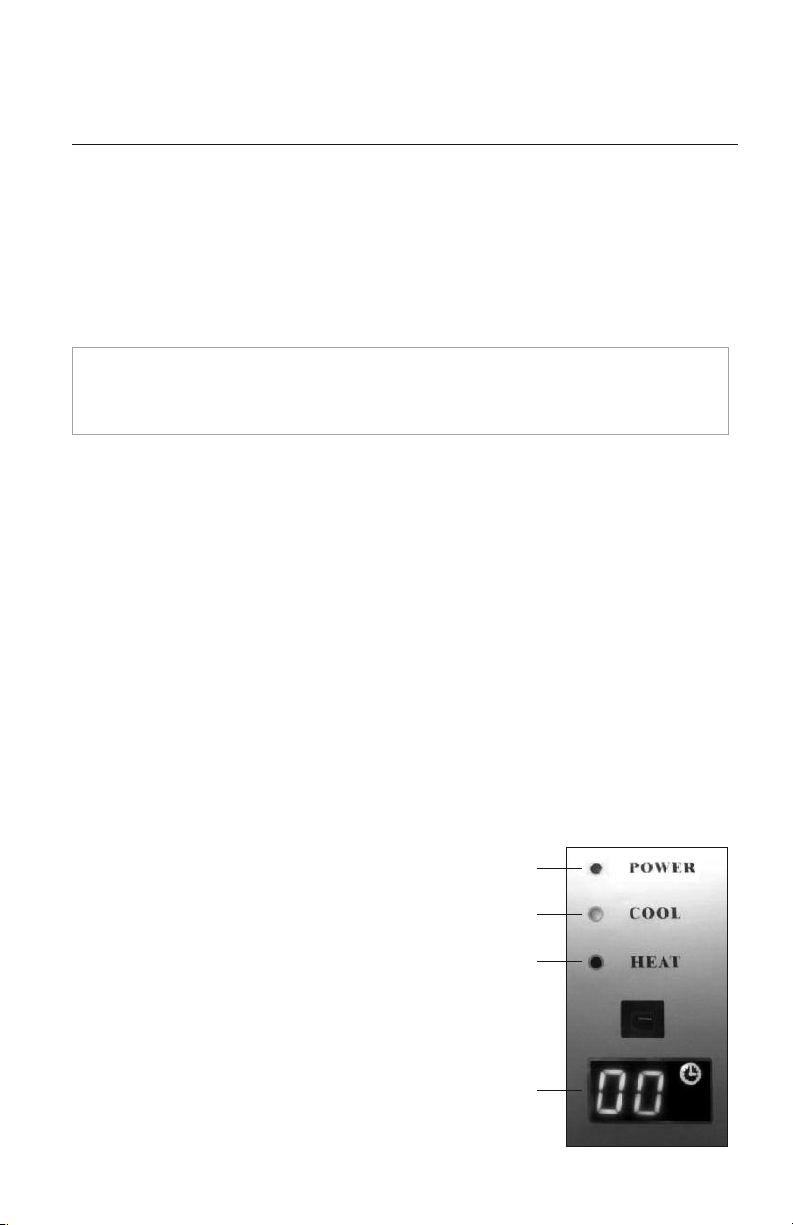
OVERVIEW OF DISPLAY PANEL
1. Power Indicator:
Power indicator will be on after electrical power is
turned on, while it will be off after disconnecting power.
2. COOL Indicator:
COOL indicator will be on after COOL mode is activated
while it will be off after COOL mode is turned off.
3. Heat Indicator:
HEAT indicator will be on after HEAT mode is activated,
while it will be off after HEAT mode is turned off.
4. Indoor setpoint and temperature display.
1
2
3
4
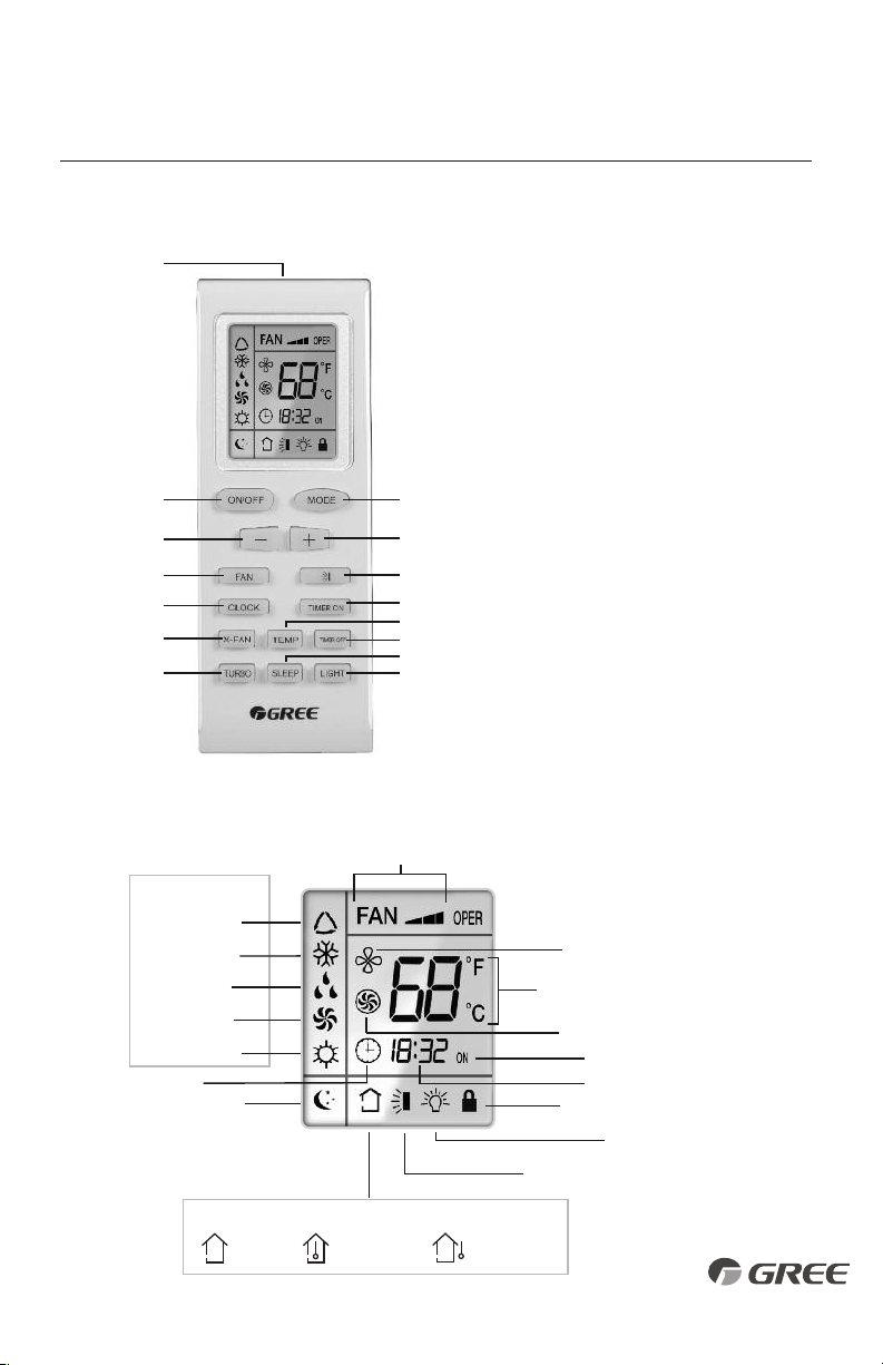
Remote Controller
INTRODUCTION FOR ICONS ON DISPLAY SCREEN
OPERATION OF WIRELESS REMOTE CONTROLLER
Part Name
1 Signal Transmitter
2 ON/OFF Button
3 Mode Button
4 – Button
5 + Button
6 Fan Button
7 Swing Button
8 Clock Button
9 Timer ON Button
10 X-Fan Button
11 Temp Button
12 Timer OFF Button
13 Turbo Button
14 Sleep Button
15 Light Button
1
2
4
6
8
10
13
3
5
7
9
11
14
12
15
Auto Mode
Cool Mode
Dry Mode
Fan Mode
Heat Mode
Clock
Sleep Mode
Set Fan Speed
Operation Mode
X-Fan Mode
Set Temperature
Set Time
Timer On
Privacy Lock
Up & Down Swing
Light
Set Temp.
Indoor
Ambient Temp.
Outdoor
Ambient Temp.
Temp. Display Type
Turbo Mode
9
The wireless remote controller is the interface between the user and the Gree U-Match
system. Commands are entered by the user to control the system. Any command that has
been entered with the remote controller will remain in memory until it is changed by the
user or the batteries are replaced.
When entering commands, point the remote controller in the direction of the unit. The unit
will emit an audible beep when the signals are received correctly.
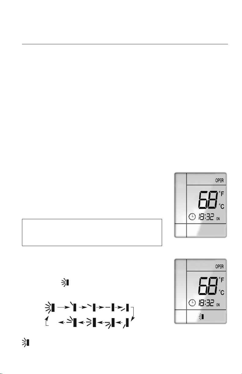
ON/OFF BUTTON
When you press the ON/OFF button,“OPER” icon will be displayed
and the unit will start in the last operating mode and room setpoint.
When you press the ON/OFF button again, the “OPER” icon will
disappear and the unit will shut down. The remote controller will
display the time and last room setpoint.
NOTE: If the ON/OFF button is pressed too soon after a
stop, the compressor will not start for 3 minutes due to the
inherent protection against frequent compressor cycling.
OPERATION OF WIRELESS REMOTE CONTROLLER
REMOTE CONTROLLER OPERATIONS
The wireless remote controller is sleek, versatile and allows you to change room temperatures
and functions on your U-Match Floor/Ceiling system from the palm of your hand. The large
LCD display and buttons make it easy-to-understand and easy-to-use.
The remote controller is set from factory to display temperatures in°F. If °C is desired, turn the
remote OFF and then press “MODE“ and “
––
” buttons on the remote simultaneously.
ON Mode Display
SWING LOUVERS
Press the Swing Louver button to select five different vertical
(up & down) air discharge directions including Continuous Sweep.
The Swing Louver icon will be displayed. Press this button
to set swing angle, which changes in direction as below:
Indicates louver swings back and forth in the five directions, as shown.
OFF
10234
8
7
65
Swing Louver Display
10
OPERATION OF WIRELESS REMOTE CONTROLLER
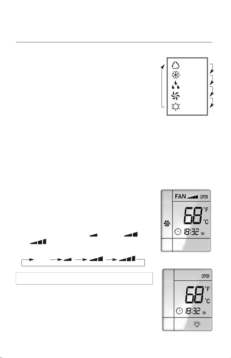
MODE BUTTON
Use the “MODE” button to select one of the available modes.
The selected mode will be displayed on the remote controller
and the appropriate icon will be displayed.
AUTO – Unit will automatically select heating or cooling to
maintain room temperature between 68°F and 77°F.
The remote controller will display the Auto Mode icon with
no setpoint. The front panel display will show "77."
COOL – To cool to selected setpoint and remove moisture.
System varies compressor speed to maintain desired temperature.
HEAT – To heat to selected room setpoint. System varies compressor speed to maintain
desired room temperature.
FAN ONLY – To circulate air without heating or cooling. Use Fan Speed button to select
speed from low to high.
DRY – Select DRY MODE to increase moisture removal
during warm humid conditions. In Dry mode the indoor fan
will run at low speed during the cooling cycle. When setpoint
is reached, the indoor fan will turn off with the compressor.
: AUTO
: COOL
: DRY
:
FAN ONLY
: HEAT
Icons Displayed
FAN BUTTON
By pressing this button, AUTO, LOW ( ), MEDIUM ( ), or
HIGH ( ), speeds can be circularly selected. AUTO is the
default fan speed after Power ON.
NOTE: In DRY mode, fan speed is not adjustable, it will remain at LOW.
Fan Button
LIGHT BUTTON
Press the LIGHT button to turn On or Off the display on the
Floor/Ceiling unit. When the indoor unit first powers on, the
display will default to ON. The LIGHT icon will display when
the front panel display is ON.
Light Display
AUTO
11
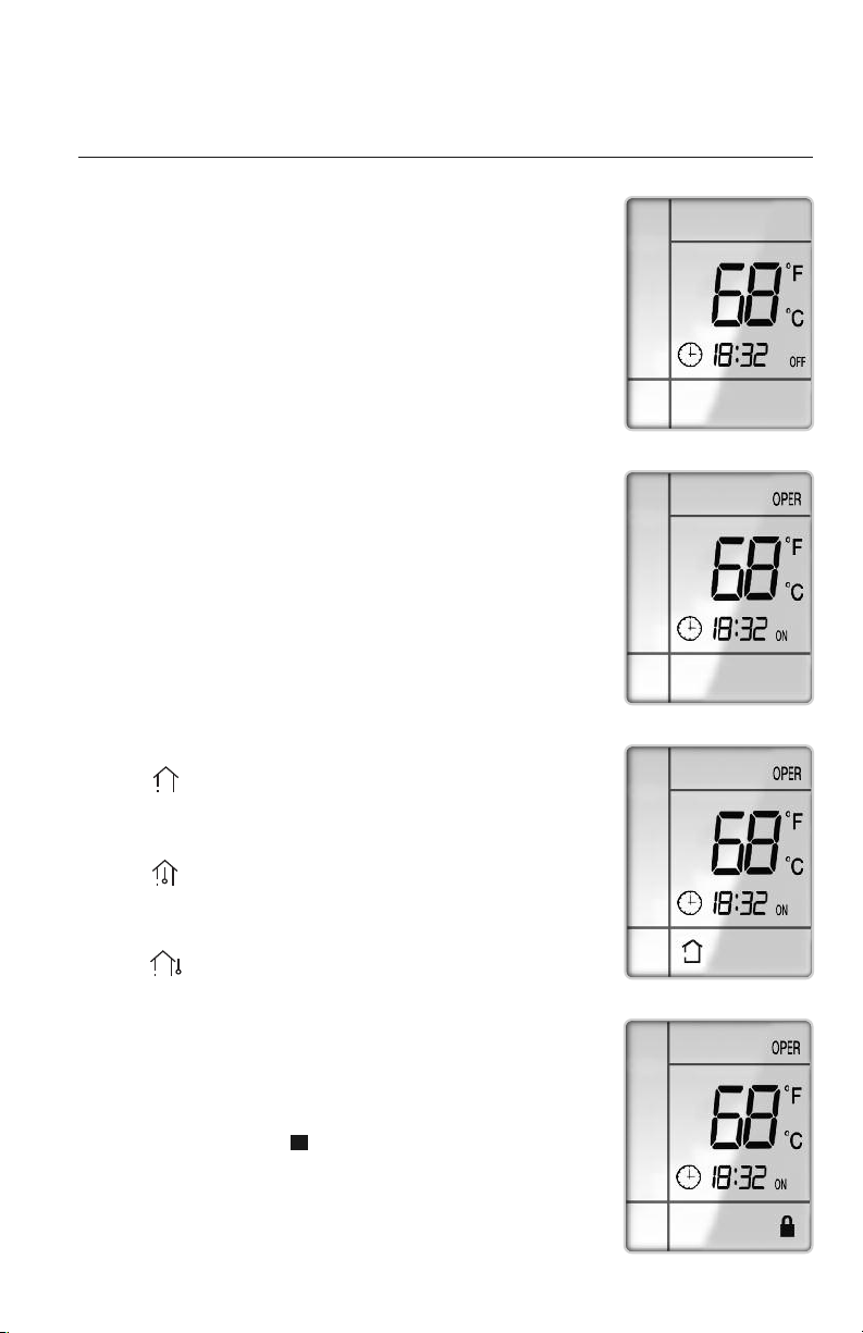
PRIVACY LOCK MODE
The Privacy Lock prevents unauthorized access to the unit controls
and prevents tampering with system settings. The remote controller
can be locked by pushing the "+" and "-" buttons simultaneously
for 2 seconds. The Privacy Lock icon will be displayed on the remote
controller. Repeat the process to unlock the remote controller.
U
Privacy Lock Display
When the “TEMP” button is pushed once, the temperature
indicator is displayed. This indicates that the setpoint
temperature is displayed.
When the “TEMP” button is pushed a second time, the display will
show an icon with a
thermometer inside a house. This indicates
that the room temperature is displayed.
When the "TEMP” button is pushed a third time, the display will
show an icon with a thermometer outside a house. This
indicates that the outdoor temperature is displayed. (Not available
on some models).
The room temperature and outdoor temperature will be displayed
for only 5 seconds before reverting back to displaying room setpoint.
OPERATION OF WIRELESS REMOTE CONTROLLER
TIMER ON MODE
The Floor/Ceiling unit can be programmed to automatically turn
ON
after a selected time period. With the unit in
OFF
mode, press
TIMER
button to activate the
TIMER
mode, and the
ON/OFF
icon will begin
blinking. Press + or - button to select a time setting from 0.5 to 24
hours. Press once for slow adjustment and hold down for fast
adjustment.
Press
TIMER
button to confirm settings, and icon will
stop blinking. The unit will turn
ON
after the selected time period.
TIMER OFF MODE
The Floor/Ceiling unit can be programmed to automatically turn
OFF
after a selected time period. With the unit in ON mode, press
TIMER
button to activate the
TIMER
mode, and the
ON/OFF
icon will begin
blinking. Press + or - button to select a time setting from 0.5
to 24 hours. Press once for slow adjustment and hold down for fast
adjustment. Press
TIMER
button to confirm settings, and icon will
stop blinking. The unit will turn
OFF
after the selected time period.
Timer ON
Timer OFF
TEMP BUTTON
Temp Button
12
OPERATION OF WIRELESS REMOTE CONTROLLER
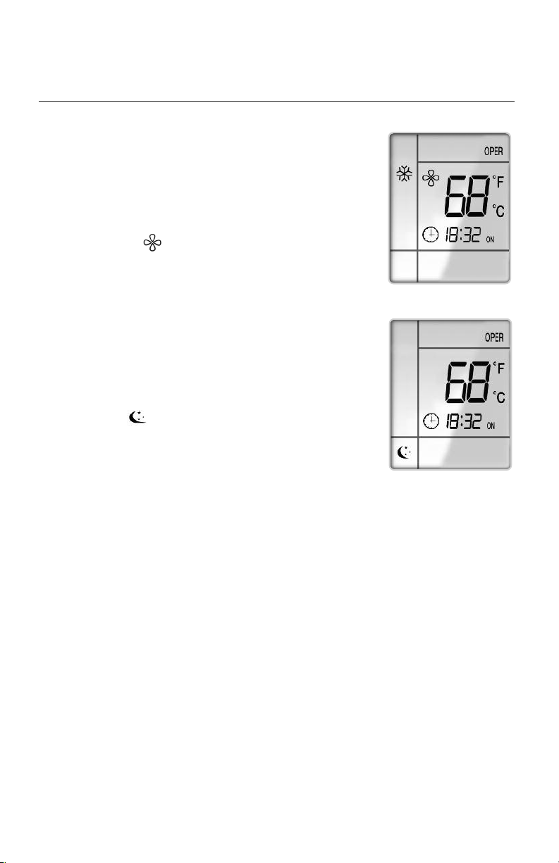
SLEEP MODE
The unit will automatically adjust room temperature during
your sleep time. This slight change in temperature will not affect
your comfort level due to the natural effects that sleeping has
on the body, but it will save on energy consumption and will
lower your electric bill. Press the SLEEP button to select Sleep
Mode. The SLEEP icon will appear.
In Cool or Dry modes:
If setpoint is between 61℉ to 73℉, temperature will slowly
increase 2℉ per hour for 3 hours, then maintain this setpoint
for 4 hours, then reduce setpoint by 2℉ and hold at this
setpoint until Sleep Mode is cancelled.
If setpoint is between 74℉ to 81℉, temperature will slowly increase 2℉ per hour for 2 hours,
then maintain this setpoint for 5 hours, then reduce setpoint by 2℉ and hold at this setpoint
until Sleep Mode is cancelled.
If setpoint is between 82℉ to 85℉, temperature will slowly increase 2℉ per hour for 1 hour,
then maintain this setpoint for 6 hours, then reduce setpoint by 2℉ and hold at this setpoint
until Sleep Mode is cancelled.
If setpoint is 86℉, unit will run at this setpoint for 7 hours, then reduce setpoint by 2℉ and
hold at this setpoint until Sleep Mode is cancelled.
In Heat mode:
If setpoint is between 82 ℉ to 86℉, the unit will slowly reduce setpoint by 2℉ per hour for
3 hours, and then maintain this setpoint until Sleep Mode is cancelled.
If setpoint is between 69 ℉ to 81℉, the unit will slowly reduce setpoint by 2℉ per hour for
2 hours, and then maintain this setpoint until Sleep Mode is cancelled.
If setpoint is between 63℉ to 68℉, the unit will reduce setpoint by 2℉, and then maintain
this setpoint until Sleep Mode is cancelled.
If setpoint is 62℉, the unit will run at this setpoint until Sleep Mode is cancelled.
X-FAN MODE
When operating in humid areas, the unit has a DRY COIL
function
called X-Fan that will allow the indoor fan to run for a
pre-determined
amount of time after the unit is turned off
(cooling or dry modes) to ensure that additional moisture is
removed from coil. Push the “X-FAN” button to enable this
feature. The X-FAN icon will be displayed on remote
controller. To deactivate this feature, push the “X-FAN”
button again.
X-Fan Mode Display
Sleep Mode Display
13
OPERATION OF WIRELESS REMOTE CONTROLLER
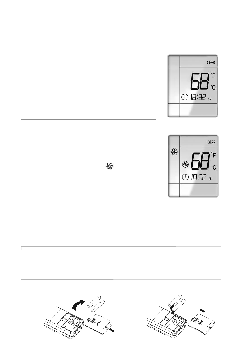
CLOCK BUTTON
Press the CLOCK button to enter Clock Setup Mode. The clock icon
will begin flashing. Set the clock by pressing the + or - buttons.
Press once for slow adjustment; press and hold down for fast
adjustment. When finished, press the CLOCK button to save your
clock settings. This is the current time, not the timer setting.
NOTE:
Clock time adopts 24-hour mode. A 12-hour format
is not available.
CHANGING BATTERIES AND ADDITIONAL NOTES
To change batteries, slide cover off battery compartment on back of remote controller. Remove
and safely discard old batteries. Insert two new AAA 1.5V dry batteries, using correct polarity.
Reattach back cover.
NOTE:
• If the remote controller will not be used for a long time, remove batteries to prevent leakage damage.
• Be sure to aim the remote controller at the receiver of the main unit when operating.
• When remote emits a signal, icon will flicker; a tone will be heard when unit receives that signal.
Remove
old batteries
Install
new batteries
CHANGING BATTERIES
Clock Display
TURBO MODE
The desired room setpoint can be achieved faster in TURBO
mode. After selecting the“HEAT”or“COOL” mode button,
push the“TURBO”button. The TURBO icon will be
displayed on the remote controller and the unit will run at an
ultra-high speed. To deactivate the feature, push the“TURBO”
button again. The unit will return to normal operation.
Turbo Mode Display
14
Take notice of the following items before cleaning your air conditioning unit.
• To avoid electric shock or injury, do not attempt to clean the unit unless both the indoor
and outdoor units have been turned off and disconnected from the main power supply.
• Do not wash the unit with water; this may cause an electric shock.
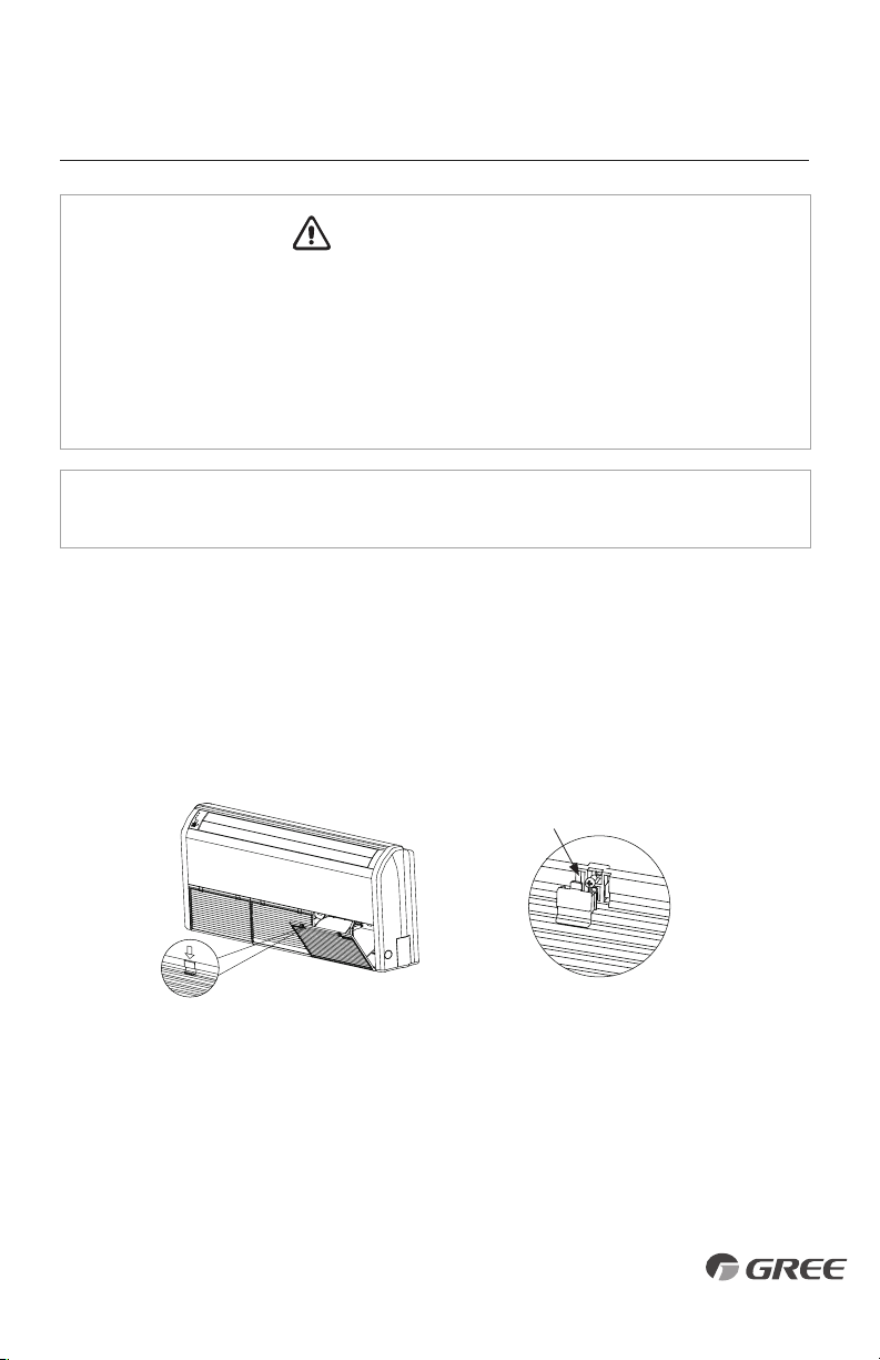
AIR FILTER CLEANING
Changing your air filter on a regular basis prevents many problems. Dirty air filters will affect
the performance and the longevity of your unit. It is recommended that air filters be cleaned
every three months.
1. Open the air inlet grille by unfastening the two clasps, as shown.
2. Remove the screws under the clasps with a screwdriver and open the inlet grille.
3. Clean dust, lint and dirt from the air filter using a vacuum cleaner or washing with water.
If dirt is conspicuous, wash with a mild detergent in lukewarm water. After washing air
filter with water, let dry before re-installing them.
4. Reinsert the air filter into the filter door. Be careful to align it properly.
5. Close filter door and tighten the locking screws with a screwdriver.
CARE AND CLEANING
15
NOTE: Do not use bleach, abrasives or water above 113°F (45°C) as it may cause
discoloration or damage to the surface of the unit.
Remove the screw
WARNING
CAUTION
WARNING
WARNING
16
TROUBLESHOOTING
PROBLEM
System does not restart.
Indoor unit emits unpleasant odor
when started
You hear a“water flowing”sound.
A thin fog or vapor coming out
of the indoor unit when system is
running.
You hear a slight cracking sound
when the system stops or starts.
The system will not run.
The unit is not heating or cooling
adequately.
Water leakage from the
outdoor unit.
CAUSE/SOLUTION
Cause: The system has a built-in three-minute delay to prevent short and/or rapid
cycling of the compressor.
Solution: Wait three minutes for the protection delay to expire.
Cause: Typically unpleasant odors are the result of mold or mildew forming on
the coil surfaces or the air filter.
Solution: Wash indoor air filter in warm water with mild cleaner. If odors persist,
contact a qualified service professional to clean the coil surfaces.
Cause: It is normal for the system to make“water flowing”or “gurgling”sounds
from refrigerant pressures equalizing when the compressor starts and stops
Solution: The noises should discontinue as the refrigerant system equalizes after
two or three minutes.
Cause: It is normal for the system to emit a slight fog or water vapor when
cooling extremely humid warm air.
Solution: The fog or water vapor will disappear as the system cools and
dehumidifies the room space.
Cause: It is normal for the system to make “slight cracking” sounds from parts
expanding and contracting during system starts and stops.
Solution: he noises will discontinue as temperature equalizes after 2 or 3 minutes.
Cause: There are a number of situations that will prevent the system from running.
Solution: Check for the following:
• Circuit breaker is “tripped” or “turned off.”
• Power button of remote is not turned on.
• Batteries in the remote controller are low.
• Remote controller is in sleep mode or timer mode.
• Otherwise, contact a qualified service professional for assistance.
Cause: There are a number of reasons for inadequate cooling or heating.
Solution: Check the following:
• Remove obstructions blocking airflow into the room.
• Clean dirty or blocked air filter that is restricting airflow into the system.
• Seal around door or windows to prevent air infiltration into the room.
• Relocate or remove heat sources from the room.
Cause: It is normal for the outdoor unit to generate condensate water in the
reverse cycle heating and defrost mode.
Solution: This is normal. No action is required.
16
TROUBLESHOOTING
PROBLEM
Water leaking from the indoor
unit into the room.
Wireless remote controller
does not work.
The unit will not deliver air.
Moisture or condensation
on the discharge air louvers
or outlet vents.
CAUSE/SOLUTION
Cause: While it is normal for the system to generate condensate water in
cooling mode, it is designed to drain this water via a condensate drain system
Solution: If water is leaking into the room, it may indicate one of the following.
• The indoor unit is not level right to left. Level indoor unit.
• The condensate drain pipe is restricted or plugged. All restrictions must
be removed to allow continuous drainage by gravity.
• If problem persists, contact a qualified service professional for assistance.
Cause: There are a number of possible reasons
Solution: Check the following:
• The batteries might be low. Change the batteries.
• The remote controller must be within 25 ft. (7.6 m) with no obstructions
of the indoor unit. If remote controller needs to be replaced, contact a
qualified service professional for assistance. In the meantime, use the
wired controller to operate the system.
Cause: There are a number of system functions that will prevent air flow.
Solution: Check for the following:
• In heating mode, the indoor fan may not start for three minutes if the
room temperature is very low. This is to prevent blowing cold air.
• In heat mode, if the outdoor temperature is low and humidity is high,
the system may need to defrost for up to 12 minutes before beginning
a heating cycle.
• In dry mode, the indoor fan may stop for up to three minutes during the
compressor off delay.
• Otherwise, you should contact a qualified service professional for assistance.
Cause: It is normal for the system to develop condensation or moisture on the
discharge air louvers when cooling warm humid air for a long period of time.
Solution: The condensation or moisture will disappear as the system cools and
dehumidifies the room space.
Stop operation and call for service in the following circumstances:
• You hear a harsh or unusual sound during operation.
• Water is leaking in the room.
• You notice a burning smell or see smoke.
• Circuit breaker trips frequently, or unit stops abnormally often.
17
WARNING
CAUTION
WARNING
CAUTION
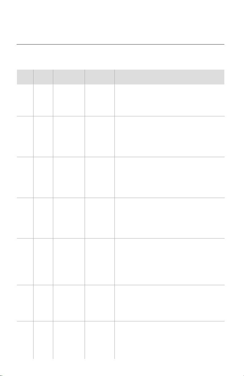
DIAGNOSTIC CODES
No.
1
2
3
4
5
6
Description
If outdoor unit detects the high pressure switch is cut off for 3-sec
successively, high pressure protection will occur. All the loads
(except the 4-way valve in heating mode) will be switched off.
In this case, all the buttons and remote control signals except
ON/OFF button will be disabled and system won't be recovered
automatically. Switch off the unit or re-energize the unit after
cutting off power to eliminate this protection.
If indoor unit detects the evaporator temperature is lower than
protective temperate value after the unit has been running for a
period of time under cooling or dry mode, the unit will report this fault,
in which case the compressor and outdoor fan motor will be stopped.
The unit will not run until evaporator temperature is higher than
the protective temp. value and the compressor is stopped for 3-min.
If outdoor unit detects low-pressure switch is open during ON or
standby state within 30-sec successively the unit will report a low
pressure protection. If the fault occurs 3 times successively within
30-min, the unit will not recover automatically.
If the unit reports low refrigerant level within 10-min after turning on
the unit, the unit will stop operation. If the fault occurs successively
3 times, the unit cannot be recovered automatically.
If the unit enters refrigerant recovery mode through special
operation, E3 will be displayed. After exiting refrigerant recovery
mode, the code will disappear.
If outdoor unit detects the discharge temperature is higher than
protective temperature value, the unit will report high discharge
temperature protection. If the protection occurs over 6 times, the
unit cannot be recovered automatically. Switch off the unit or
re-energize the unit after cutting off power to reset this protection.
If the outdoor unit does not receive data from indoor unit,
communication malfunction will be reported. If there is
communication abnormality between display board and indoor
unit, communication malfunction will be reported.
If the indoor unit does not receive signal from indoor fan motor
for 30-sec successively when the fan motor is operating, indoor
fan motor malfunction will be reported. In this case, the unit can
automatically resume operation after stopping. If the malfunction
occurs 6 times within one hour, the unit cannot be recovered
automatically. Switch off the unit or re-energize the unit after
cutting off power to eliminate this malfunction.
Error
Code
E1
E2
E3
E4
E6
E8
Malfunction
Name
High Pressure
Protection
Indoor Coil
Freeze
Protection
Low Pressure
Protection
Low
Refrigerant
Protection
Refrigerant
Recycling
Mode
Compressor
High Discharge
Temperature
Protection
Communication
Malfunction
Low Indoor
Airflow
Origin of
Malfunction
High Pressure
Switch
Indoor
Evaporator
Temperature
Sensor
Low Pressure
Switch
Compressor
Discharge
Temperature
Communication
Failure Between
Indoor and
Outdoor Main
Board
Indoor
Fan Motor
Error Codes
The U-Match System has on board diagnostics. The indoor unit and Tether Controller will display
error codes. The following is a summary of the codes with explanation:
18
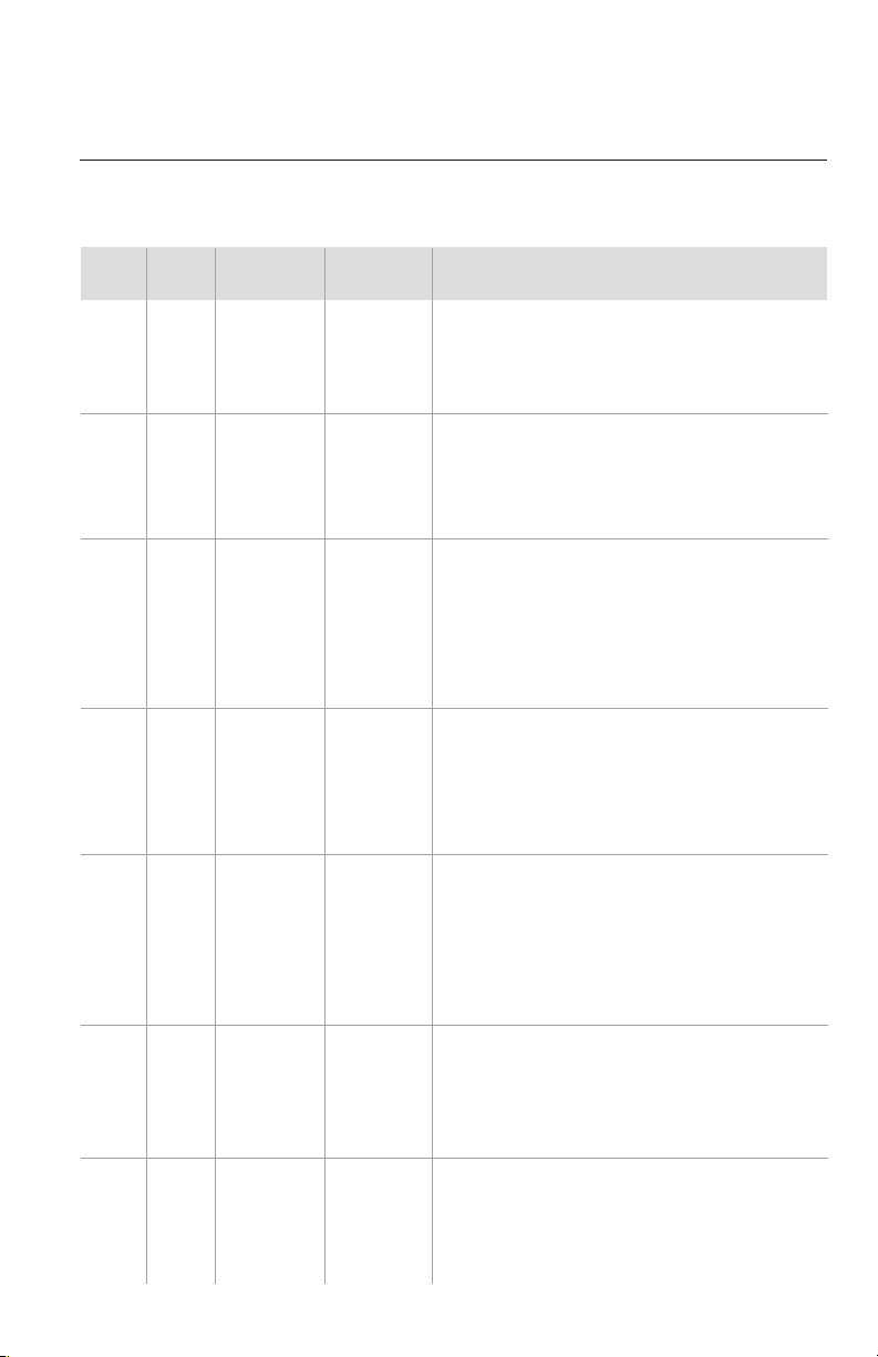
DIAGNOSTIC CODES
No.
7
8
9
10
11
12
13
Description
If indoor unit detects the condensate overflow switch warning for
8-sec successively, the system will enter condensate overflow
protection. The unit will shut off and will not recover automatically.
Switch unit off and then switch it on to eliminate this malfunction.
If indoor unit detects the indoor ambient temperature sensor is open
circuit or short circuit for 5-sec successively, indoor ambient temp.
sensor malfunction will be reported. The unit can automatically
resume operation after the malfunction disappears. If indoor ambient
temperature sensor malfunction occurs in fan mode, only the error
code is displayed and the indoor unit will operate normally.
If indoor unit detects the evaporator temperature sensor is open
circuit or short circuit for 5-sec successively, evaporator temperature
sensor malfunction will be reported. The unit can automatically
resume operation after the malfunction disappears. If evaporator
temperature sensor malfunction occurs in fan mode, only the error
code is displayed and the indoor unit will operate normally.
If outdoor unit detects the condenser coil temperature sensor open
circuit or short circuit for 5-sec successively, condenser coil temperature
sensor malfunction will be reported. The unit can automatically
resume operation after the malfunction disappears. If condenser
temperature sensor malfunction occurs in fan mode, only the error
code is displayed and the indoor unit will operate normally.
If outdoor unit detects the outdoor ambient temperature sensor
open circuit or short circuit for 5-sec successively, outdoor ambient
temperature sensor malfunction will be reported. The unit can
automatically resume operation after the malfunction disappears.
If outdoor ambient temperature sensor malfunction occurs in fan
mode, only the error code is displayed and the indoor unit will
operate normally.
If outdoor unit detects the compressor discharge temperature
sensor is open circuit or short circuit for 5-sec successively after
the compressor has been operating for 3-min, outdoor discharge
temperature sensor malfunction will be reported. The unit can
automatically resume operation after the malfunction disappears.
If the wired Tether Controller detects open circuit or short circuit
of its temperature sensor for 5-sec successively, wired controller
temperature sensor malfunction will be reported.
Error
Code
E9
F0
F1
F2
F3
F4
F5
Malfunction
Name
Condensate
Overflow
Protection
Indoor Ambient
Temperature
Sensor at
Return Air Inlet
Malfunction
Indoor
Evaporator Coil
Temperature
Sensor
Malfunction
Indoor
Condenser Coil
Temperature
Sensor
Malfunction
Outdoor
Ambient
Temperature
Sensor
Malfunction
Compressor
Discharge
Temperature
Sensor
Malfunction
Wired
Controller
Temperature
Sensor
Malfunction
Origin of
Malfunction
Overflow
Switch
Indoor
Ambient
Temperature
Sensor
Evaporator
Coil
Temperature
Sensor
Condenser
Coil
Temperature
Sensor
Outdoor
Ambient
Temperature
Sensor
Compressor
Discharge
Temperature
Sensor
Wired
Tether
Controller
Temperature
Sensor
Error Codes
19
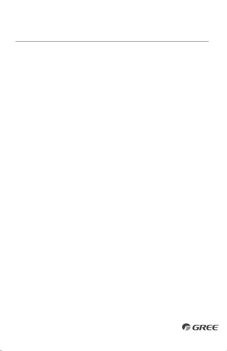
DIAGNOSTIC CODES
No.
14
15
16
17
18
19
20
Description
If the memory chip of outdoor drive circuit board fails, the unit will
not start. The unit will not recover automatically. If thermo junction
cannot be eliminated after switching off the unit and then energizing
the unit several times, replace the outdoor drive circuit board.
If outdoor unit detects the compressor overload switch open within
3-sec successively, the unit will report compressor overload protection.
If the fault occurs successively 3 times, the unit will not recover
automatically. Switch off the unit or re-energize the unit to eliminate
this protection.
If indoor unit detects the evaporator coil temperature is higher
than protective temp. value, the unit will report overload protection.
The unit will restart operation after evaporator temperature is lower
than the protective temp. value and the compressor is stopped for
3-minutes. If the protection occurs over 6 times, the unit will not
recover automatically. Switch off the unit or re-energize the unit
to eliminate this protection.
If outdoor unit does not receive feedback signal from outdoor fan
motor for 30-sec successively when the fan motor is operating, an
outdoor fan motor malfunction will be reported. In this case, the unit
can automatically resume operation after stopping. If the malfunction
occurs 6 times within one hour, the unit will not recover automatically.
Switch off the unit or re-energize the unit to eliminate this malfunction.
After the compressor starts operation in heating mode, if the outdoor
unit detects the difference between evaporator temperature and
indoor ambient temperature is lower than the protective value for
10-min successively, Reversing Valve Malfunction will be reported
and the outdoor unit will stop operation. If the malfunction occurs
3 times, the unit will not recover automatically. Switch off the unit
or re-energize the unit to eliminate this malfunction.
If the outdoor main control board does not receive data from drive
board, communication malfunction between main control and drive
will be reported. The malfunction will be eliminated automatically.
If the memory chip on the outdoor main control board fails, the
unit will not start. The unit will not recover automatically. If thermo
junction cannot be eliminated after switching the unit off and on
for several tries, replace the outdoor main control board.
Error
Code
ee
H3
H4
H6
U7
P6
EE
Malfunction
Name
Outdoor
Drive
Memory Chip
Malfunction
Compressor
Overload
Protection
Overload
Protection
Outdoor
Fan Motor
Malfunction
Reversing or
4-way Valve
Malfunction
Main Control
and Drive
Communication
Malfunction
Outdoor
Main Control
Memory Chip
Malfunction
Origin of
Malfunction
Outdoor Drive
Board
Compressor
Overload
Switch
Evaporator
Temperature,
Condenser
Temperature
Outdoor
Fan Motor
Reversing/
4-way Valve
Communication
Failure Between
Indoor and
Outdoor Main
Board
Outdoor
Main Control
Board
Error Codes
20
21
ENERGY SAVING TIPS
1. Reduce room setpoint at night: During the nighttime hours you don't require the
same level of conscious cooling or heating. Try using Sleep Mode to gradually relax
room temperature and allow the unit to run less and save energy.
2. Curtains and shades: In the summer, it is recommended to block the effects of the
sun. Close window curtains and shades on the south and west side of your home to
help block solar heat. In winter, the sun is your friend. Open curtains and shades to
allow solar heat into your room.
3. Close doors: If you don’t need to heat and cool your whole home, confine the heating
and cooling to one room by closing doors.
4. Service the unit: Some basic maintenance might be all you need. The outdoor unit
will greatly benefit from a good hosing off, especially in treed areas where seeds and
other debris can stick to coil fins and make the unit work up to 15% harder!
5. Rearrange the room: Furniture that obstructs airflow means you could be heating
and cooling the back of a chair instead of the actual living space. Remove or rearrange
obstacles blocking airflow.
6. Try 75 degrees: 75°F is a good point for an air conditioner to run at its optimal
performance level. Even a 5-degree change in temperature can make your unit use
up to 40% more energy.
7. Lighting: Turning lights off can help reduce your heat. Each light bulb is a tiny heater.
Your air conditioner must waste energy overcoming the heat from your lights to reach
and hold your desired room temperature.
8. Is anyone home? If possible, while you're away turn your unit to Auto mode and
make sure windows and curtains are closed. Although room temperature may be less
than optimal for a few minutes when you return, the unit will soon have the room
back to your desired temperature.
9. Don't forget the fan: The fan is much like a car. The faster it runs, the more energy it
uses. Sometimes we need the car to go fast, but slow is good enough most of the time.
Try saving money by using the comfortable quiet low fan speed as much as possible.
GREE ELECTRIC APPLIANCES, INC.
www.greecomfort.com
LIMITED WARRANTY
GREE distributor (hereinafter “Company”) warrants this product against failure due to defect in materials or workmanship under normal use and maintenance as
follows. All warranty periods begin on the date of original installation. If the date cannot be verified, the warranty period begins one hundred twenty (120) days from
date of manufacture. If a part fails due to defect during the applicable warranty period Company will provide a new or remanufactured part, at Company’s option,
to replace the failed defective part at no charge for the part. This limited warranty is subject to all provisions, conditions, limitations and exclusions listed below.
• Seven (7) years on compressor and Five (5) years on all parts to the original registered end‐user.
• One (1) year warranty on remote controller unit.
• Proper installation – Limited warranty applies only to systems that are installed by a state certified or licensed HVAC contractor, under applicable local and
state law in accordance with all applicable building codes and permits; GREE installation and operation instructions and good trade practices.
• Warranty applies only to products remaining in their original installation location.
• Defective parts must be returned to the distributor through a registered servicing dealer for credit.
LIMITATIONS OF WARRANTIES: ALL IMPLIED WARRANTIES AND/OR CONDITIONS (INCLUDING IMPLIED WARRANTIES OR CONDITIONS OF MERCHANTABILITY
AND FITNESS FOR A PARTICULAR USE OR PURPOSE) ARE LIMITED TO THE DURATION OF THIS LIMITED WARRANTY, SOME STATES OR PROVINCES DO NOT ALLOW
LIMITATIONS ON HOW LONG AN IMPLIED WARRANTY OR CONDITION LASTS, SO THE ABOVE MAY NOT APPLY TO YOU. THE EXPRESS WARRANTIES MADE IN THIS
WARRANTY ARE EXCLUSIVE AND MAY NOT BE ALTERED, ENLARGED, OR CHANGED BY ANY DISTRIBUTOR, DEALER, OR OTHER PERSON, WHATSOEVER.
THIS WARRANTY DOES NOT COVER:
1. Labor or other costs incurred for diagnosing, repairing, removing, installing, shipping, servicing or handling of either defective parts, or replacement parts,
or new units.
2. Normal maintenance as outlined in the installation and servicing instructions or Owner’s Manual, including filter cleaning and/or replacement and lubrication.
3. Failure, damage or repairs due to faulty installation, misapplication, abuse, improper servicing, unauthorized alteration or improper operation.
4. Failure to start due to voltage conditions, blown fuses, open circuit breakers, or damages due to the inadequacy or interruption of electrical service.
5. Failure or damage due to floods, winds, fires, lightning, accidents, corrosive environments (rust, etc.) or other conditions beyond the control of the Company.
6. Parts not supplied or designated by Company, or damages resulting from their use.
7. Products installed outside USA and Canada.
8. Electricity or fuel costs, or increases in electricity or fuel costs from any reason whatsoever, including additional or unusual use of supplemental electric heat.
9. Any cost to replace, refill or dispose of refrigerant, including the cost of refrigerant.
10. Any special, indirect or consequential property or commercial damage of any nature whatsoever. Some states or provinces do not allow the exclusion of
incidental or consequential damages, so the above limitation may not apply to you.
For additional warranty exclusions, visit www.GreeComfort.com
.
This warranty gives you specific legal rights, and you may also have other rights which vary from state to state or province to province.
For warranty service or repair, contact your installing contractor. You may find the installer’s name on the equipment or in your Owner’s packet.
Complete product registration below and send back by e‐mail at
service@twclimate.com
PRODUCT REGISTRATION
Model No.
Serial No. Date of Installation
Owner Name
Address of Installation
Installing Contractor
Address
Phone No. / E-mail
WSO021513-DLSWARR-HP- Rev. 12-4-14
Gree Electric Appliances, Inc ©2019 Cat No: GREE_U-MATCH_OWNERS_FLOOR CEILING_043019