Owners
Manual
FOR POTABLEWATER
HEATING ONLY
NOT SUITABLEFOR
SPACEHEATING.
FOR USE ONLY IN
MOBILE HOMES
Model No.
MODEL NUMBERS:
153.333830 30 Gal.
153.333930 40 Gal.
Caution:
Read and Follow
All Safety Rules and
Operating Instructions
Before First Use of
This Product.
SavethisManual for Future Reference.
T
ECONOMIZERs5
GAS WATER HEATER
• Safety Instructions
• Installation
• Operation
• Care and Maintenance
• Troubleshooting
• Parts List
For Your Safety
AN ODORANT IS ADDED TO THE GAS USED BY THIS
WATER HEATER
WARNING: If the information in these instructions are not foi-
l lowed exactly, a fire or explosion may result, causing property
[damage, personal injury or death.
-Do not store or use gasoline or other flammable vapors and liq-
uids in the vicinity of this or any other appliance.
-WHAT TO DO IF YOU SMELL GAS
: Do not try to light any appliance.
Do not touch any electrical switch; do not use any phone in your
building. . .
i Immediately call your gas suppher from a ne,ghbor's phone.
Follow the gas supplier's]nstructions.
If you can not reach your gassupplier, call the fire department.
-Installation and service must be performed by a qualified installer,
service agency or the gassupplier.
• . . A' WARNING I
Improper ,nstallatlon, adlustment, alterat, on, service or malntenance J
can cause DEATH, SERIOUS BODILY INJURY, OR PROPERTY DAM-I
AGE: Refer to this manual for assistance or consult the local Sears]
Service Center or gasutl ity for further reformation. I
_WARNING I
Flammable vapors may be drawn by air currents from other areas
of the structure to thzs apphance.
I --WARNING I
READ THE GENERAL SAF_N BEGINNING ON INSIDE
COVER AND THEN THIS ENTIRE MANUAL BEFORE INSTALLING
OR OPERATING THIS WATER HEATER.
Sears, Roebuck and Co., Hoffman Estates, IL 60179 U.S.A.
Safety Precautions
I A,WARNING
Improper installation, adjustment, alteratiod;'3entne-e_
maintenance can cause DEATH, SERIOI_. BODILY
INJURY,OR PROPERTYDAMAGE. Referto .thism_l_r
assistanceor consult your local Sears Ser_ce_Conter f_r
further information.
_1,WARNING
WATER HEATERSEQUIPPED FOR ONE TYPE GASONLYr.
Thiswaterheaterisequippedfor onetypegasonl_ Che_ _e
medalratlngplatenearthe gascontrol valseforthe correctga_
DO NOT USETHISWATERHEATERWITH ANY GASOTHER
THAN THE ONE SHOWN ON THE MODELRATINGPLATE.
Failureto usethe correctgascancauseproblemswhichcan
result in DEATH, SERIOUSBODILY INJURY,OR PROPERTY
DAMAGE.If youhaveanyquestionsor doubtsconsultyourgas
supplieror localatilit_
AWARNING
INSTALLATIONSIN AREASWHERE FLAMMABLEUQUIDS
(VAPORS) ARE LIKELY TO BE PRESENT OR STORED
(GARAGES., STORAGE, AND UTILITY AREAS, ETC):
FlammableIKluids(suchasgasoline,solvents,propane(LP) or
butane, etc.), all of whichemit flammable vapors,may be
improperlystoredor usedin sucharea_The gaswater heater
pilotlightor mainburnercanignitesuchvaporLThe resulting
flashl__ckandfire cancausedeathor seriousburnsto anyonem
the ares,aswellasprepertydamage.
If instailatloninsuchareasisyouronly option,then theinstaila-
tlon mustbe accomplishedin a waythat the pilotflameand
mainburnerflameareelevatedfrom theflooratleast18inches
While this mayreducethe changesofflammablevaporsfrom
floorspillbeingignited,gasolineandotherflammablesubstance
shouldneverbe storedor usedin shesameroom or areacon-
talninga gaswater heateror otheropenflameorsparkproduc-
ingappliance.
NOTE: Flammablevaporsmaybe drawnbyair currentsfrom
othorareasofthestructuretotheappliance.
-AWARNING
Ifthis waterheaterwillbeusedin beautyshops,barbershops,
cleaningestablishments,or self-servicelaundrieswith dry
cleaningequipment,it is imperativethat the water heateror
waterheatersbe installedsothat combustionandventilation
air bu takonfrom outsidethesearm_, Referto the "Factsto
ConsiderAbout the location" sectionofthis manualandalso
the latestedition oftheNationalFuelGasCode,ANSI7.223.1,
alsoreferredto asNFPA 54 for specificsprovidedconcerning
airrequired.
A, WARNING I
A fire can start if combustible materials such as clothing,]
I cleaningmaterials, or flammable liquidsare placedagainst
[ or next to the water heater.
mentsfor ReliefValvesandAutomaticGasShutoff Devicesfur
ANS,Z21.22bya... on ly
nizedtos_ng laboratorythat maintainsperiodecinspe_on of
productionoflistedequipmentormaterials.
The valvemust be markedwith a maximum set pressurenot
to exceedthe marked hydrostaticworkingpressureof the
water heater(150 Ibsdsq.in.)anda dischargecapacitynot less
than the.waterheaterinput_ as.shownonthe modelrating
plate.(Electricheaters- watts dividedby 1000x 3415equal
BTU/Hr.rate.)
Yourlocalj-risdi_onal authority,whilemandatingthe useof a
tempereture-prossurerailervalvecomplyingwith ANSIZ21.22
and ASME,mayrequire a valsemodeldifferentfromthe one
furnishedwiththewaterheater.
Compliancewith suchlocalrequirementsmust besatisfiedby
the installer or enduserof the .w_a._r heaterwith a locallyp_-
scribedtemperature-pressurerehefvalveinstalledin the deslg-
natodopeningin shewaterheater in placeofthe factoryfur-
nishedvalve.
Forsafeoperationofthe waterheater,the reliefvalvemustnot
beremovedfromi_ designatedopeningor plugged.
The temperature-pressurerelief valvemustbe installeddirectly
intothe fittingofthe water heaterdesignatedforthereleefvalve.
Positionthe valvedownwardand providetubingsothat anydis-
chargewill exit onlywithin 6 inchesabove,or at anydistance
belowthe structuralfloor.Be certainthat no contactismade
with anyEveelectricalpart.The dischargeopeningmustnotbe
blockedor reducedin sizeunderanycircumstances.Excessive
length,over30feet,or useofmore thanfourelbowscancause
restrictionandreducetiledischargecapacityofthevalve,
No valveor otherobstructionisto beplacedbetweentherelief
valveandthe tank.Do not connecttubingdirectlyto discharge
drainunlessa6" airgapisprovided.Topreventbodilyinjury,haz-
ardto life,or propertydamage,the reliefvalvemustbeallowed
to dischargewaterinquantitiesshouldcircumstancesdemand.If
the dischargepipeisnot connectedto a drainor othersuitable
means,the waterflowmaycausepropertydamage.
The DischargePipe:
Must not be smallerin sizethan the outlet pipesizeof she
valve,orhaveanyreducingcouplingsor otherrestrictions.
Mustnotbepluggedor blocked.
Mustbeofmateriallistedforhotwater distribution.
Must beinstalledso asto allow completedrainageof both
the temperature-pressurerelief valve, and the discharge
pipe.
Mustterminate at anadequatedrain.
Mustnothaveanyvalvebetweenshereliefvalveandtank.
Safety Precautions
&WARNING
Ages water beZer cannotoperateproperlywithoutthe cor-
rectamoontof air for combustio_Do not installin a canfi_d
areasuchacloset,unleasyou prorideair asshovmin_e "Facts
to ComidurAbootthe Locatioo"sectlo_ Neverobsmuctthe
Ilowofvantllatlondr. Ifyou haveanyduu_ or quos6omat a_
callyoorgesc_. Failureto providethe_ amoootof
combust_nmrcanresultin a tim or explceionand cencause
DEATH,SERIOUSBODILYINJUI_,ORPROPERTYDAMAGE.
&WARNING
Thiswatorhoatorrm.t oot beinmlleddirec_ oocerp_n_
Carpeting must be protected by a metal or wood panel
beneaththe applianceextendingbeyondthe full width and
depth ofthe appliancebyat _ 3 inches(76.2mm) in anyI
di_ or if sheappilaoceisinstagedinan alcoveor closet,i
the an_m Iloormostbecoreredbythepenel.Failureto heed
this warningm_/result inatimhazard.
&WARNING
HOTTERWATERCAN SCALD:Water beatersareintendedto
ps_l.ucehotwater.Water heatedto a temperatu_ whichwill
satisfyclotheswashing,d'mhwashing,andothersanit_ng needs
canscaldandpermanan_ injureyou upen€ootact.Somepeo-
dearemorelikelyto bepermanendyinjured byhotwaterthan
lylmentallyhandicapped.If_ usinghotwaterinyourhome
fitsinto oneofthesugroupsocifthereisaiucalceduor statelaw
requiringacerteJntemperaturewaterat thehotwatertap,then
_u musttakespecialprecautions.In additiontousingthelowest
mssibletemperature.se_ngthatsatisfiesyourhotwaterneeds,
Lmeanssuchasa mixingvalve,shouldbeusedat thehotwater
tapsusedbythesepeopleor at thewater heate_.Mixingvalves
am avmZableat plumbingsupplyor hardwarestore_Followmap
ufacturersinstructionsfor installationof the valves.Before
changingthe factory setting on the thermostat, read the
'fl'emperetureRegulation"sectioninthismanual.
AWARNING I
Soot build-upindicatesa problem that requires correction
beforefurther u_. Turn"OFF" gasto watorheaterandleave
"OFF" until repelrsam made, becausefailureto correctthe I
causeof the sootingcanresultin a fire or explosioncausing
DEATH,SERIOUSBODILYINJUR_,OR PROPERTYDAMAGE.I
&WARNING
VENT DAMPERS-Any ventdamper,_ it isoperoted
thermallyor otherwisemustberemosndifitsuseInhibitsprop
er_ ofthe waterhe.an
ThermallyOperatedVent Dampers:Gas-firedwater heaters
havingthermalef_cinncyin excessof80_ mayproducea mla-
tlvelylowfluegastemperoture.Sochtempera_._s mayoot be
high enough to properly open thermally operated vent
dampers`Thiswauld causespigngeoffluegasesandmaycanse
_.boomoooxk_peisooin_
Ventdampersmustbearevidenceof certiflca_ooascompiylng
with the latesteditionof American NationalSt_nclardANSI
Z21.6g(AN..Sl7.21.66& 67, ,,_o_y, _ _ and
mechanicallyactuatedventdampers)Beforemst_latlon ofany
ve.ntdampe_consultyour.localSearsServiceCenterort_ gas
utilityforfurther information.
&WARNING
•The applianceand itsindividualshutoffvalvemustbe discon-
nectedfrom thegassupplypipingsysm_duringanypressure
testing of the gassystemat test pressuresin excessof V2
poundper squareinch(3.51dPa).
•The appliancemustbeisolatedhornthe gassupplypiping sys-
tem by dosingits individualmanualshutoff valveduringany
pressuretestingofthe gassupplypiping systemat test pres-
suresequalor lessthan_ poundpersquareinch(3.5kPa).
A,WARNING
BEFORElIGHTING PROPANE(LR) GASWATERHEATER_
Prupane(LR) gesisbearier than air.Shouklthere be a leakin
the system,the gaswill settle near the ground.Basements,
crawl speces,skirtedareasunder mobde homes(evenwhen
ventilated),closetsand areasbelow groundlevelwill serveas
pocketsfor theaccumulationof this ge_ Beforeat_PJnpdngto
Ilightor relight_ water heater_pilot or turningon a nearby
electricallightswitch,be absolutelysurethereis noarcumulat.
edgasin the area.Searchfor odorof gasbymifEngat ground
levelinthe vicinityofthe appliance.If odorisdetected,follow
stepsindicatedat "For YourSafety"on the coverpageofthis
manu_thenleavethe premise_.
AWARNING
:Chemicalvapor corrosionof the flue and vent systemma_
occurIf air for combustioncontainscertainchemicalvapors.
Spray.canpm._.lants, dean!ngsolvents,refrigeratorand air
conditionerrefrigerants, swimmingpool chemicals,calcium
andsodiumchloride,waxes,bleach,andprocesschemicalsare
itypicalcompoundswhicham potentiallycorrosive.
_,WARNING
Obstructedordebmoratedvent systemsmaypresenta serious
healthrisk or asphyxiatlo,.
3
Safety Precautions continued on page 4
Safety Precautions
AWARNING
Tbe water hoater with dr_ hood installedmustbe properly
ventedto a chimneywhichmTninatesoutdoors,Never oper-
atothe watorheataranlessit isventedtothe outdoorsandhas
.adequa_air supplyto aroid r_lcsofi_ op_r_on, _lo -I
slon or _
_LWARNING
Minimum clurances between the water heater and com-I
bustible€on,,_eructionare I" at the _dos and rear,4" at the
freat, and6' fromthe veatpipe.CJearance_om the tep oftheI
dra_ hoed is12".Refertothebbel onthewaterheaterlocatedI
ACAUTION
WATER HEATERSEVENTUALLY LEAK:Installationof the
water hearermint bea,:omllbed in sucha mannerthat if
the tankor my cennectlom shouklleak,theflowofwat_ will
not causedama_ to tbe se.uceee.When suchlectern can-
not be avoided,a suitabledrainpanshouldbe iostailedunder
the water heater.Drain pare areavailableat yourlocalSean
store,Sucha drainpan mustbe not greaterthan 1'/2inches
deep,havea minimum lengthand widthof at least2 inches
greaterthan thewa_r heater dlmensioosandmustbe piped
to an_m_e drair.The panmustnotrestrictcombostionair
tlow.Under nodncumstancasisthe rnanubctureror Searsto
be held liable for anywater damagein connectionwi_ this
wa_erheater.
AWARNING
Donot usuthis_liance if_ i_'t ofit h_ beenunderwm_r.
Immediately call a SearsService Technicianto Inspectthe
applianceandto replacethe gascontrolor anypart of the
homer systemwhichhasbeenunderwater.
AWARNING
HYDROGEN GAS: Hydrogengascanbe producedin a hot
water systemthat hasnot been usedfor a king periodoftime
(generallytwo weeks.or more). Hydrogengasisextremely
flammaF.leand explos_e.To preventthe possibilityof injury
undertheseconditions,we recommendthe hot water faucet
be openedfor suveralminutesat the kitchen sinkbeforeany
electricadapplianceswhith areconnectedto the hot watersys-
tem are used(suchas a dishwasheror washingmachine).If
hydrogengasispresent, there will probablybe an unusual
soundsimilar to airescapingthrough thepipeasthehot water
faucetisopened.There must be no smokingor openflame
nearthefaucetat thetimeit isopen.
_, WARNING
INSULATING JACKETS:When installingan externalwater
beatarinsulatlonjacket onagaswater heater,
DO NOT coverthetempereture-pressurerebefvalve.
DO NOT put imula_onoveranypart of the top ofthe ges
waterbeater.
DO NOT putinsulationoverthegsscontrolvalveor gascon.
trolvalverourner€over,or anyaccessarcesto thebereer.
DO NOT let insula_onaroundthe gasweter heaterto get
within8inchesoftbe floor(airmustgetto_e berner).
DO NOT coveror remove operatinginstructions,andsafety
related warninglabelsand mateHais affixedto the water
beaten
_ilure to heed this will result in the possibilityof a fire or
explosion.
"able of Contents
c___ietyPrecautions ...........:................................................................................................................................24
able of Contents ................................................................................................................................................5
;ustomer Responsibilities .......................................................................................................................6
"oduct Specincations"_ .................................................................................................................._...............6
;aterials and Basic Tools Needed ...............................................................................................7
Materials Needed ...................................................................................................................................................................... 7
Basic Tools................................................................................................................................................................................ 7
_stallation Instructions ........................................................................................................................8-18
Removing the Old Water Heater .......... ..................................................................................................................................... 8
Facts to Consider About the Location .................................................................................................................................. 9-10
Securing Water Heater to Floor and Wall................................................................................................................................ 11
Water Piping ..................................................................................................................................................................... 11-12
Temperature-Pressure Relief Valve........................................................................................................................................... 13
.Filling the Water Heater .......................................................................................................................................................... 14
Venting .............................................................................................................................................................................. 14-15
Gas Piping .............................................................................................................................................................................. 15
"Fuel Conversion Instructions .......................................................................................................................................... 16-17
Installation Checklist .............................................................................................................................................................. 18
--)peratin_ Instructions ........................................................................................................................._9-21
_" "-"Hghting ............................................................................................................................................................................. 19-20
Temperature Regulation .......................................................................................................................................................... 21
:ervice and Adjustment ......................................................................................................................22-23
Tank {Sediment) Cleaning ...................................................................................................................................................... 22
Burner Inspection ................................................................................................................................................................... 22
Burner Cleaning ..................................................................................................................................................................... 22
Draining ................................................................................................................................................................................. 22
Temperature-Pressure Relief ValveOperation .......................................................................................................................... 23
Drain V£ve Washer Replacement ........................................................................................................................................... 23
Housekeeping ......................................................................................................................................................................... 23
Service .................................................................................................................................................................................... 23
)oubleshooting Guide ........................................................................................................................24-25
Start Up Conditions .....:..7:. ................................................................................................................................................... 24
Condensation ....................................................................................................................................................................... 24
Smoke/Odor ......................................................................................................................................................................... 24
Thermal Expansion ............................................................................................................................................................... 24
Strange Sounds ..................................................................................................................................................................... 24
Operational Conditions .......................................................................................................................................................... 25
Smelly Water ......................................................................................................................................................................... 25
Air in Hot Water Faucets ...................................................................................................................................................... 25
High Temperature Shut Off System ...................................................................................................................................... 25
Not Enough Hot Water ........................................................................................................................................................ 25
Water is too Hot ................................................................................................................................................................... 25
Leakage Checkpoints .............................................................................................................................................................. 26
_arts Order List ...............................................................................................................................................2s-29
Customer Responsibilities
Thank You for purchasinga Sears water heater. °
Properly installed and maintained, it should give you years of
trouble free service. If you should decide that you want the new
water heater professionally installed by Sears call the local Sears
Service Center or any Seats store. They will arrange for prompt,
quality !nstallation by Searsauthorized contractors.
Abbrevmuom Found In This Instruction Manual
A.G.A. - American Gas Aasodation
A.N.S.I. - American National Standards Institute
N.EP.A. - National FireProtection Agency
The gas fired water heater is design certified by the
American Gas Association Laboratories under
American National Standards for Gas Water
Heaters for Installation in Manufactured Houses,
(Mobtle Homes).
instructions to Mobile Home Manufacturers:
The installation must conform with the
Manufactured Home Construction and Safety
Standard for Mobile Home Construction and Safety
Title 24 CFR, Part 3280 (Formerly the Federal
Standard for Mobile Construction and Safety Title
24 (Part 200), 1975.
Instruction for replacement installation:
The installation must conform with the instructions
in this manual; gas company rules; and Local Codes,
or in the absence of Local Codes, with the latest edi-
tion of the National Fuel Gas code, ANSI Z223.1,
also referred to as NFPA 54. This publication isavail-
able from your local government or public library or
gas company or by writing NFPA, Bacterymarch
Park, Quincy, MA 02269.
• Read the _Safety Precautions" section, pager 2 through 4 of
this manual first and then the entire manual carefully. If you
don't follow the safety rules, the water heater will not operate
properly. It could cause DEATH, SERIOUS BODILY
INJURY AND/OR PROPERTY DAMAGE.
This manual contains instructions for the installation, opera-
tion, and maintenance of the gas-fired water heater. It also
contains warnings through out the manual thatyou must read
and be aware oF.All warnings and .11instructions are essential
to the proper operation of the water heater and your safety.
Since we cannot put everything on the Fastfew pages, READ
THE ENTIRE MANUAL BEFORE ATI'EMP'HNG TO
INSTALL OR OPERATE THE WATER _IL
The gas fired water heater is design certified by the American
Gas Association Laboratories under American National
Standards for Gas Water Heaters for Installation in
ManufacturedHouses, (Mobile Homes).
Instructionsto Mobile Home Manufacturers:
The installation must conform with the ManufacturedHome
Construction and Safety Standard for Mobile Home
Construction and Safety Title 24 CFIL Part3280 (Formerly
the FederalStandard for Mobile Construction and SafetyTitle
24 (Part 280), 1975.
Instruction for replacement installation:
The installation must conform with the instructions in this
manual; gas company rules;and LocalCodes, or in the absence
of Local Codes, with the htest edition of the National Fuel Gas
code, ANSI Z223.1, alsoreferred to asNFPA 54. This publica-
tion is availablefrom your local government or public library
orgas company orby writing NFPA, Batrerymarch Park,
Quincy, MA 02269.
If'after reading this manualyou have any questions or do not
understand any portion of the instructions, call the Sears
Service Center.
Carefully plan the place where you are going to put the water
heater. Correct combustion, vent action, and vent pipe instal-
lation are very important in preventing death from possible
carbon monoxide poisoning and fires.
Examine the location to ensure the water heater complies with
the _Facts to Consider About the Location" section in this
manual.
For California installation this water heater must be braced,
anchored, or strapped to avoid falling or moving during an
earthquake. See instructions for correct installation proce-
dures. Instructions may be obtained from your local dealer,
wholesaler, public utilities or California Office of the State
Architect, 400 P Street, Sacramento, CA 95814.
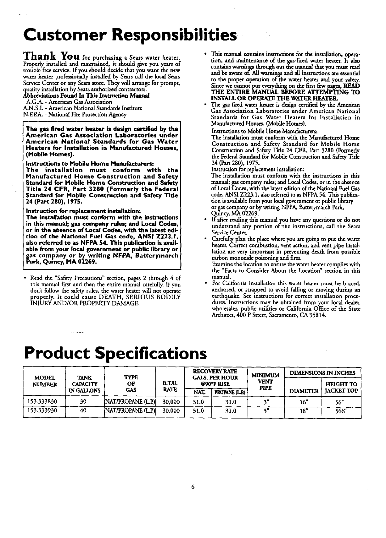
Product Specifications
MODEL
NUMBER
153.333830
153.333930
TANK
CAPACITY
IN GALLONS
30
40
TYPE
OF
GAS
NAT/PROPANE(L.P.I,
T
N?_ /PROPANE(L.P.,
B.T.U.
RATE
30,000
30,000
RECOVERY RATE
GAI_. PER HOUR
@90°F RISE
NAT. PROfaNE(Lit)
31.0 31.0
31.0 31.0
MINIMUM
VENT
PIPE
3 n
3"
DIMENSIONS IN INCHES
HEIGHT TO
DIAMETER JACKET TOP
16" 56"
18" 56½"
6
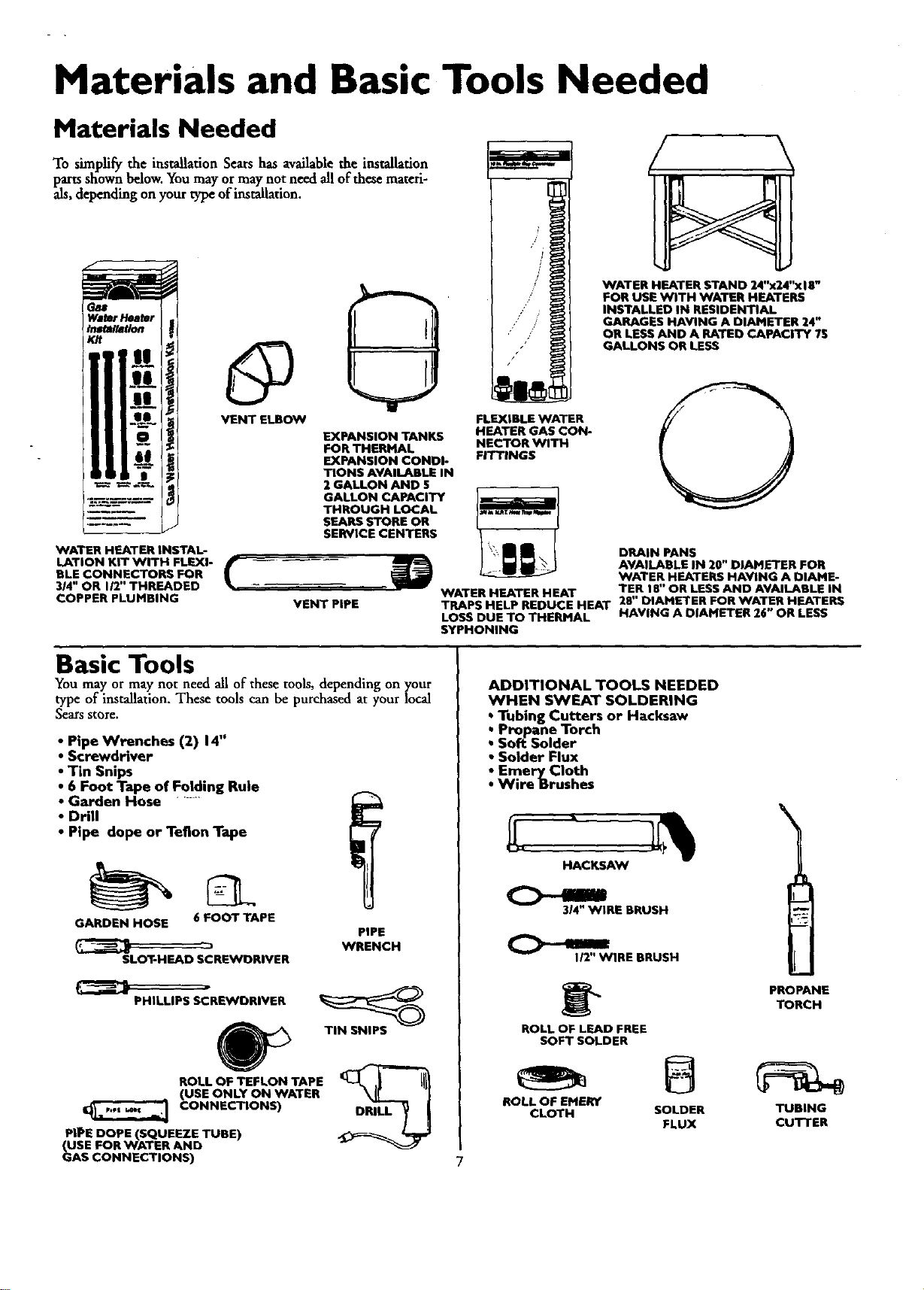
Materials and Basic Tools Needed
Materials Needed
To simplify the installation Sears has available the installation
parts shown below. You may or may not need all of these mateti-
als, depending on your type of installation.
WATER HEATER INSTAL-
LATION KIT WITH FLEXI-
BLE CONNECTORS FOR
314" OR 112"THREADED
COPPER PLUMBING
VENT ELBOW
EXPANSION TANKS
FOR THERMAL
EXPANSION CONDI-
TIONS AVAILABLE IN
2 GALLON AND 5
GALLON CAPACITY
THROUGH LOCAL
SEARS STORE OR
SERVICE CENTERS
FLEXIBLE WATER
HEATER GAS CON-
NECTOR WITH
FITTINGS
VENT PIPE
WATER HEATER STAND 24"x24"xl E"
FOR USE WITH WATER HEATERS
INSTALLED IN RESIDENTIAL
GARAGES HAVING A DIAMETER 24"
OR LESS AND A RATED CAPACITY ?S
GALLONS OR LESS
O
DRAIN PANS
AVAILABLE IN 20" DIAMETER FOR
WATER HEATERS HAVING A DIAHE-
WATER HEATER HEAT TER 18" OR LESS AND AVAILABLE IN
TRAPS HELP REDUCE HEAT 28" DIAMETER FOR WATER HEATERS
LOSS DUE TO THERMAL HAVING A DIAMETER 26" OR LESS
SYPHONING
Basic Tools
You may or may not need all of these tools, depending on your
type of installation. These tools can be purchased at your local
Sears store.
• Pipe Wrenches (2) 14"
• Screwdriver
• Tin Snips
• 6 Foot Tape of Folding Rule
• Garden Hose ......
• Drill
• Pipe dope or Teflon Tape
GARDEN HOSE 6 FOOT TAPE
SLOT-HEAD SCREWDRIVER
PHILLIPS SCREWDRIVER
ROLL OF TEFLON TAPE
(USE ONLY ON WATER
CONNECTIONS)
PIPE DOPE (SQUEEZE TUBE)
(USE FOR WATER AND
GAS CONNECTIONS)
PIPE
WRENCH
TIN SNIPS
ADDITIONAL TOOLS NEEDED
WHEN SWEAT SOLDERING
• Tubing Cutters or Hacksaw
• Propane Torch
• Soft Solder
• Solder Flux
• Emery Cloth
•Wire Brushes
HACKSAW
314"WIRE BRUSH
112"WIRE BRUSH
ROLL OF LEAD FREE
SOFT SOLDER
PROPANE
TORCH
ROLL OF EPIERV
CLOTH SOLDER TUBING
FLUX CUTTER
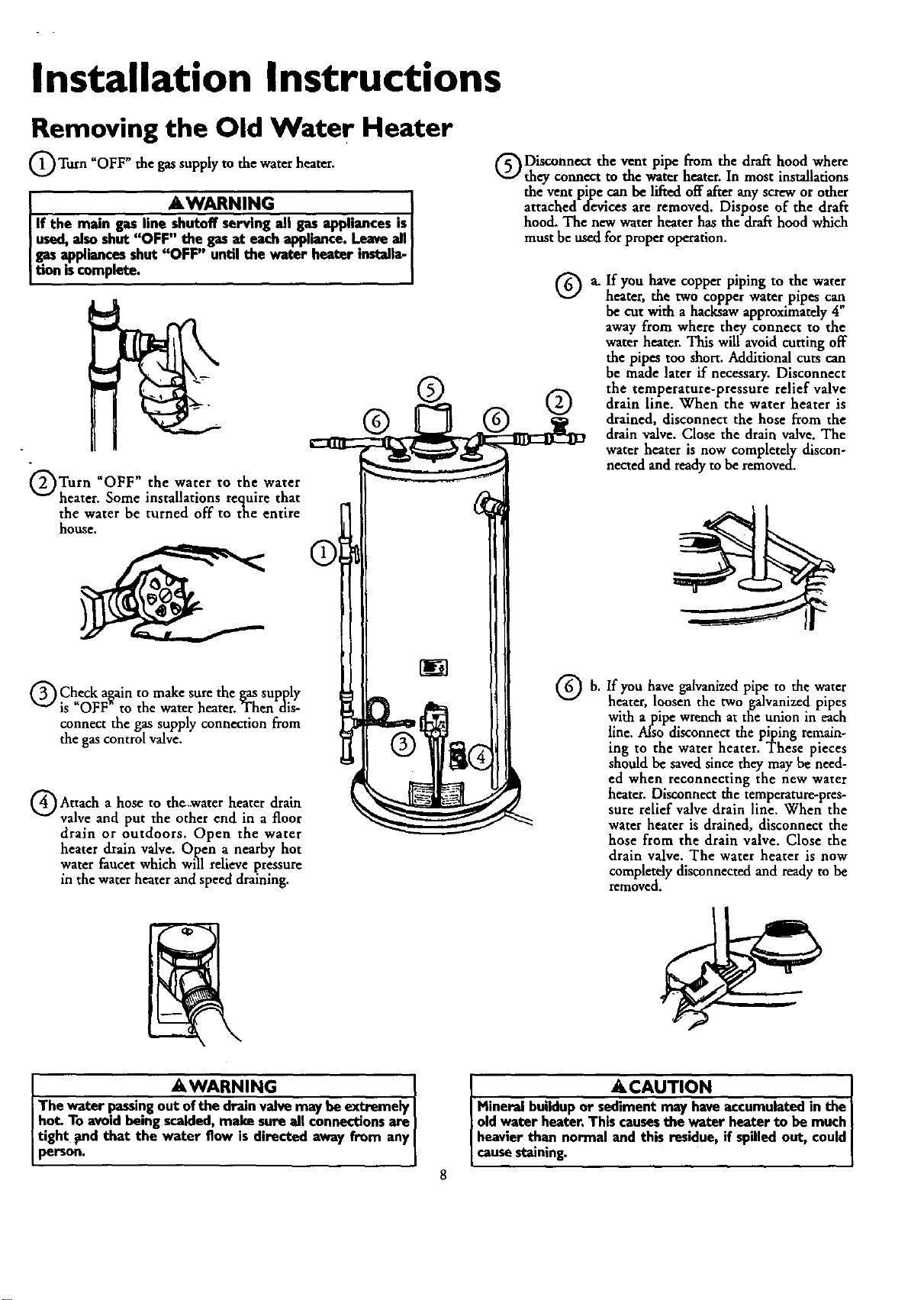
Installation Instructions
Removing the Old Water Heater
Turn _OFF _the gassupply to the water heater.
AWARNING . I
If the main gas line shutoff serving all _ apphancesisI
used,alsoshut "OFF" the gasat each appliance.Leaveall
gasappliancesshut "OFF" until the water heater installa-
tion iscomplete.
(_)Turn "OFF" the water to the water
_" heater. Some installations require that
the water be turned off to the entire
house.
Q Check again to make sure the gas supply
is "OFF _ to the water heater. Then dis-
connect the gas supply connection from
the gas control valve,
Q Attach hose thc,.waterheater drain
a to
valve and put the other end in a floor
drain or outdoors. Open the water
heater drain valve. Open a nearby hot
water faucet which will relieve pressure
in the water heater and speed draining.
®
Disconnect the vent pipe from the draft hood where
they connect to the water heater. In most installations
the vent pipe can be lifted off afterany screw or other
attached devices are removed. Dispose of the draft
hood. The new water heater has the draft hood which
must be used for proper operation.
a. If you have copper piping to the water
heater, the two copper water pipes can
be cut with a hacksaw approximately 4"
away from where they connect to the
water heater. This will avoid cutting off
the pipes too short. Additional cuts can
be made later if necessary. Disconnect
the temperature-pressure relief valve
O drain line. When the water heater is
drained, disconnect the hose from the
drain valve. Close the drain valve. The
water heater is now completely discon-
nected and ready to be removed.
b. you pipe to water
If have the
heater, loosen the two galvanized pipes
with a pipe wrench at the union in each
line. Also disconnect the piping remain-
ing to the water heater. These pieces
should be saved since they may be need-
ed when reconnecting the new water
heater. Disconnect the temperature-pres-
sure relief valve drain line. When the
water heater is drained, disconnect the
hose from the drain valve. Close the
drain valve. The water heater is now
completely disconnected and ready to be
removed.
I AWARNING ]
The water passingout ofthe drainvalvemay he extremely ]
hot. To avoidbeingscalded,make sure all connectionsare ]
tight _nd that the water flow is directed away from any[
person.
ACAUTION
Mineral buildupor sedimentmay haveaccumulated in the
oldwater heater.This causesthe water heater to he much
heavierthan normal and this residue,if spilledout, couldJ
causestaining.
Installation Instructions (cont'd)
Facts to Consider About the
Location
Whether replacing an old water heater or putting the water
heater in a new location, the following critical points must be
observed.
This mobile home gas-fired water heater is for use in a mobile
home. You should carefully choose an indoor location for the
new water heater, because the placement is a very important
consideration for the safety of the occupants in the building
and for the most economical use of the appfiance. This water
heater is for.use only in mobile homes and is not intended
for outdoor installation.
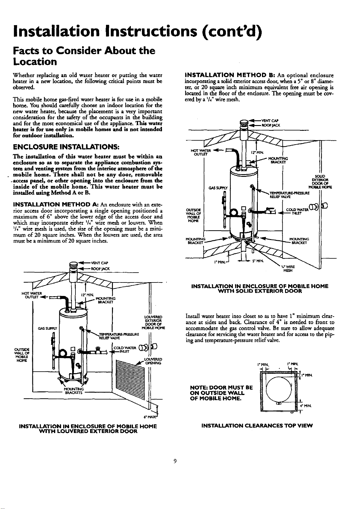
INSTALLATION METHOD B: An optional enclosure
incorporating a solid exterior accessdoor, when a 5 or 8 diame-
ter, or 20 square inch minimum equivalent fv:e air opening is
located in the floor of the enclosure. The opening must be cov-
i n •
ered by a /4 wire mesh.
ENCLOSURE INSTALLATIONS:
The installation of this water heater must be within an
endoenre so .as to separate the a]ppliance combustion sys-
tem and ventmg system from the interior atmosphere of the
. mobile home. There shall not be any door, removable
.access panel, or oth.er opening into the enclosure from the
inside of the mobsle home. This water heater must be
installed using Method A or B.
INSTALLATION METHOD _ An endosure with an exte-
rior access door incorporating a single opening positioned a
maximum of 6" above the lower edge of-the access door and
which may incorporate either '/4"wire mesh or louvers. When
%"wire mesh is used, the size of the opening must be a mini-
mum of 20 square inches. When the louvers are used, the area
must be a minimum of 20 square inches.
HOTWATER
OUTLET
GASSUPPLY
ou'rSIDE
WALt.OF
MOraLE
HOME
MOUNTING
SOLID
EXTSRIOR
DOOROF
t40_LE HOME
MESH
HOT WATER
GASSUPPLY
OUTSIDE
WALL OF
_IO_LE
HOME
MOUNTING
BRACKETS
6"I
INSTALLATION IN ENCLOSURE OF MOBILE HOME
WITH LOUVERED EXTERIOR DOOR
INSTALLATION IN ENCLOSURE OF MOBILE HOME
WITH SOLID EXTERIOR DOOR
Install water heater into closet so as to have 1" minimum dear-
ance at sides and back. Clearance of 4" is needed to front to
accommodate the gas control valve. Be sure to allow adequate
dearance for servicing the water heater and for access to the pip-
ing and temperature-pressure relief valve.
NOTE: DOOR MUST BE
ON OUTSIDE WALL
OF MOBILE HOME.
I" MIN I ° MIN.
I*MIN,
4"MIkL
INSTALLATION CLEARANCES TOP VIEVV
9
Installation Instructions (cont'd)
Facts to Consider About the
Location (cont'd)
A WARIqlNG
Minimum clearancesbetween the water heater and com-
bustibleconstructionare I" at the sidesand rear, 4" at the
front,and6" fromthevantpipe.Clearancefromthetep oftbe
jacketis12"onmostmodeb.Notethata lesserdi_ may
be allowedon somemodels Referto the labelon the water
heateradjacentto thegascontrolvalveforall deeranc_
The water heater should be secured to the floor and to the wall
of the enclosure with th,,e,mounting brackets provided. For
bracket location refer to Securing Water Heater to Floor and
Wall' in the "Installation Instruct'ons" section.
When a mobile home is skirted, an air intake opening with a
minimum free areaof 32 square inches must be provided in the
skirt. If the opening is covered by louvers orscreen, the total free
. area must be 32 square inches. Other gas firedappliances in the
home will require additional free air openings; consult these
manufacturers for correct sizing.
AWARNING
A gaswater heatercannotope...rate_ wi_out _e cor-
rect amountofair forcombast_n.Do not mstailin a confined
areasucha closet,unlessyouprovideair asshowninthe "Facts
to ConsiderAbout the Location"soc_on on page9. Never
obstructtheflow ofventilationair. If you haveanydoubtsor
questionsat all,callyour gascompanyor SearsServiceCenter,
Failureto providethe proper amountof combustionair can
result in a fire or explosionand cancauseDEATH,SERIOUS
BODILYIN)URn,ORPROPERTYDAMAGE.
&WARNING
When the systemrequireswater at temperatureshigherthan
requiredfor other uses,the hot water systemmay requirea
meanssuchas a mixing valveto be installed to temper the
water at certainpointsof use.Somepeoplearemore likelyto
bepermanentlyinjuredbyhotwaterthanothers;theseindude
the elderly,children,_e !nfirm, or the physically/mentailyhand-
icapped.Beforeimmersingyourselforanyoneelseinhotwater,
be sureto checkthe water temperature.WARNING: HOT-
TER WATER INCREASES THE RISKOF SCALD INJURY.!
(Alsosee"Temperature Regulation"section)Mixingvalvesare
available.atplumbingsupplyor hardwarestere_Followmanu-'
facturersinstructionsfor installationof thesevalves. !
_,WARNING I
Thiswater heater shai_ected to anyheatingays-I
ternsor compenent(s)previouslyusedwitha nonpotablewater I
heatingappliance. I
AWARNING
If this water heaterwill beusedin beautyshops,barbershops,
cleaningestablishments,or self-servicelaundrieswith dry
cleaningequipment,it isimperativethat the water h_J.eror
water heatersbe installedsothat combustionandven_la_on
air be takenfrom outsidethese area_ Referto the "Facts to
ConsiderAbout the Location"sectionofthis manualandalso
thelatost edition ofthe NationalFuelGasCede,ANSI Z223.1,
also referredto as NFPA54 for specificsprovidedconcerning
air required.
10
I . AWARNING I
Toxicchemicalssuchas usedfor treatment of.b.oi.'lersor non-J
potablewaterbeing appliancesshallneverbe,ntreducedintoI
a potablewaterbeatlngsystem.
I
&CAUTION
WATER HEATERSEVENTUALLY LEAK: Installationof the
w'_or beater mint be _o_mpllsbed in sucha manner_t.lf
the tankor anycoanect_m shouldleak,theflowof waterwdl
not causedamageto the structure.When suchlocationscan-
not beavoided,a suitabledrain panshouldbe installedunder
the water heater,Drain pansareavailableat your localSoars
store.Sucha drain panmust be not greaterthan 1½inches
deep,havea minimumlengthandwidth ofat least2 inches
greaterthanthe water heater dimensionsandmustbe piped
to an adequatedrain.Thepanmustnotrestrictcombustionair
flow.Underno circumstancesisthe rnanufac_reror Searsto
be heldliablefor anywater damagein connectionwith this
waterheater.
When a drain pan is required, the installation must conform to
"Method A" on page 9.
AWARNING
INSTALLATIONSIN AREASWHERE FLAMMABLELIQUIDS I
(VAPORS) ARE LIKELY TO BE PRESENT OR STORED
(GARAGES, STORAGE, AND UTILITY AREAS, ETC):
Flammableliquids(suchasgasoline,solvents,propane(LP)or
butane, etc.), all of whichemit flammablevapors,may be
improperlystoredor usedinsucharea_The gaswater heater
pilotlightor main burnercanignitesuchvapor_The resulting
flashbackandfirecancausedeathor seriousbumsto anyonein
thearea,aswellaspropertydamage.
Ifinstallationin suchareasisyour onlyoption,then the installa-
tion mustbe accomplishedin a waythat the pilot flameand
mainburnerflameareelevatedfromthe floorat least18inches.
Whilethis mayreducethe changesofflammablevaporsfroma
floorspillbeingignited,gasolineandotherflammablesubstances
shouldneverbe storedor usedin thesameroom or areacon-
_ining a gaswaterheateror otheropenflameor sparkpnxluc-
mgapplianc_
NOTE: Flammablevaporsmaybe drawnby air currentsfrom
otherareasofthestructureto tbeapprmnce.
AWARNING
Propellantsof anrosolspraysand volatilecompounds,(clean-
ers,chlorine basedchemicals,rofHgerant_etc.)in additionto
beinghighlyflammableinmanyc_ses_will alsochangeto cor-
rosivehydrochloricacid when exposedto the combustion
productsof the water heater.The resultscanbe hazardom
andalsocauseproductfailure.
AWARNING
This water heater must not be installeddirectlyon carpeting.
Carpeting must be protected by a metal or wood panel
beneath the applianceextendingbeyond the fullwidth and
depthof the appliance byat least3 inches(76.2mm) in any
direction,or ifthe applianceisinstalledin an alcoveor closet,
the entirefloormustbe coveredbythe panel.Failureto heed
this warningmayresultinafire hazard.
Installation Instructions (cont'd)
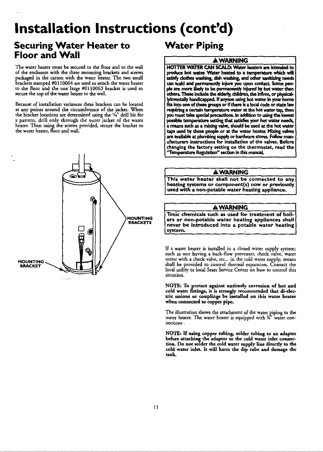
Securing Water Heater to
Floor and Wall
The water heater must be secured to the floor and to the wall
of the enclosure with the three mounting brackets and screws
packaged in the carton with the water heater. The two small
brackets stamped #0110064 are used to attachthe water heater
to the floor and the one large #0110063 bracket is used to
secure the top of the water heater to the wall.
Because of installation variances these brackets can be located
at any points around the circumference of the jacket. When
the bracket locations aredetermined using the % drill bit for
a pattern, drill only through the outer jacket of the water
heater. Then using the screws provided, secure the bracket to
the water heater, floor and wall.
Water Piping
AWARNING
HOTTERWATERCAN SCALDtWater heatersareintendedto
_hce hotwatt. Waterhea_., to a temperaturewhh..hva'll
dotheswashing,dishwadain_and othersanitizingneeds
canscaldand pennanen_ injureyouuponcontact.Somepeo-
othe_ Thesemdudetheeldor_ chHdre_theinErm,or physical-
lylm_mlallyhandicapped.Ifanyoneusinghotwaterinyourhome
fitsintooneoftheseiFoupsor ifthereisa localcodeorsta_ law
requiringa certaintern.peretumwaterat thehotwaterta_ then
youmusttakespecialprecaution_In add'_iontousingthelowest
potabletemperature,setting_aat_ yourhotwaterneedg
a meansinch asa mi_ng valve,shouldbeusedatthehot water
tapsusedbythesepeopleor at the waterheat_r.Mixlngvalves
are availableatplumbingsupplyor hardwarestore_Followman-
ufacturersinstructionsfor installationof the valves.Before
changingthe factory settingon the thermostat, read the
'q'emperetureRegulation"sectioninthismanual
MOUNTING,
BRACKET
)MOUNTING
BRACKETS
AWARNING
]This water heater shall not be connected to any
I heating systems or component(s) now or previously
I used with a non-potable water heating appliance.
- AWARNING . I
Toxic chemicals such as used for treatment of bod-
ers or non-potable water heating applmnces shall
never be introduced into a potable water heating i
system. ' i
If a water heater is installed in a closed water supply system;
such as one having a back-flow preventer, check valve, water
meter with a check valve, etc.., in the cold water supply; means
shall be provided to control thermal expansion. Contact the
local utility or local Sears Service Center on how to control this
situation.
NOTE: To protect against untimely corrosion of hot and
cold water fittings, it is strongly recommended that di-elec-
trlc unions or couplings be installed on this water heater
when connected to copper pipe.
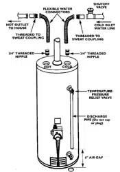
The illustration shows the attachment of the waterpiping to the
water heater. The water heater is equipped with 3A"water con-
nections.
NOTE: If using copper tubing, solder tubing to an adapter
before attaching the adaptor to the cold water inlet connec-
tion. Do not solder the cold water supply line directly to the
cold water inlet. It will harm the dip tube and damage the
tank.
11
Installation Instructions (cont'd)
Water Piping (cont'd)
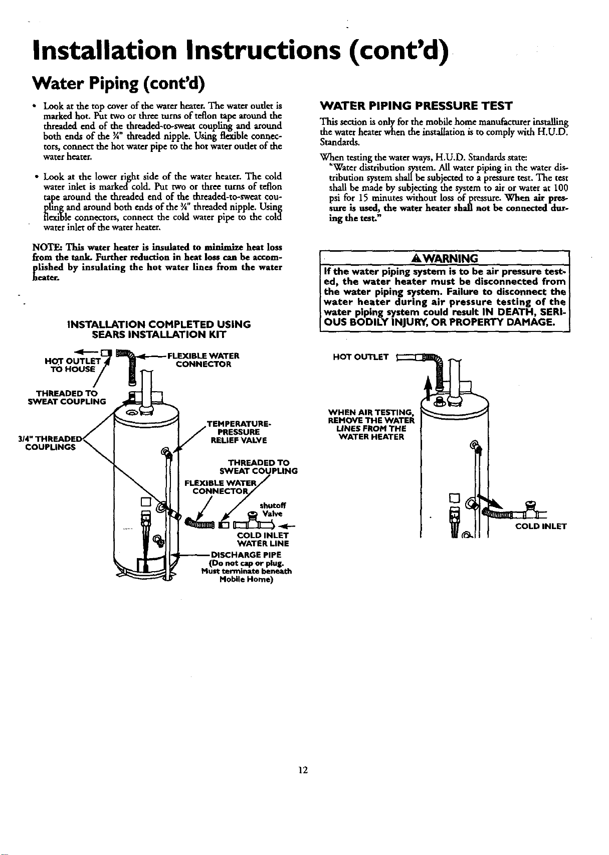
• Look atthe top cover of the water heater. The water outlet is
marked hot. Put two or three turns of teflon tape around the
threaded end of the threaded-to-sweat coupling and around
both ends of the ¾ threaded nipple. Using flexible connec-
tors, connect the hot water pipe to the hot water outlet of the
water heater.
• Look at the lower fight side of the water heater. The cold
water inlet is marked cold. Put two or three turns of teflon
tape around the threaded end of the threaded-to-sweat cou-
pling and around both ends of the _A"threaded nipple. Using
flexible connectors, connect the cold water pipe to the cold
water inlet of the water heater.
WATER PIPING PRESSURE TEST
This section isonly for the mobile home manufacturerinstalling
the water heater when the installation is to comply with H.U.D.
Standards.
When testing the water ways, H.U.D. Standards state:
"Water distribution system. All water piping in the water dis-
tribution system shall be subjected to a pressure test. The test
shaft be made by subjecting the system to air or water at 100
psi for 15 minutes without loss of ptessure. When air pres-
sure is used, the water heater shall not be connected dur-
hag the test."
NOTE: This water heater is insulated to minimize heat loss
ficom the tank. Further reduction in heat loss can be accom-
plished by insulating the hot water lines from the water
_ttero
INSTALLATION COMPLETED USING
SEARS INSTALLATION KIT
HO3" OUTL_t_
TO HOUSE/
THREADED TO
SWEAT COUPLING
CONNECTOR
PRESSURE
RELIEF VALVE
THREADED TO
SWEAT COUPLING
FLEXIBLE WATER
shutoff
COLD INLET
WATER LINE
314" THREADED_
COUPLINGS
&WARNING
If the water piping system isto be air pressure test.
ed, the water heater must be disconnected from
the water piping system. Failure to disconnect the
water heater during air pressure testing of the
water piping system could result IN DEATH, SERI-
OUS BODILY INJURY, OR PROPERTY DAMAGE.
HOT OUTLET
WHEN AIR TESTING,
REMOVE THE WATER
LINES FROM THE
WATER HEATER
COLD INLET
(Do not cap or plug.
Must terminate beneath
Mobile Home)
12
Installation Instructions (cont'd)
Temperature.Pressure Relief Valve
AWARNING
At the time of manufacture this water heater was provided
witha combinationtomperature-prassuresreliefvalvecertified
bya nationallyrecognizedtestinglaboratorythat maintains
periodicinspectionofproductionoflistedequipmentor mute-
rials, as meeting the requirements for Relief Valves and
AutomaticGasShutoffDevicesfor Hot Water SupplySystems,
and the latestedition ef ANSI 7.21.22andthe coderequire-
ments ef ASME.If replaced,the valvemustmeet the requir_
rnents eflocalcedes,but notlessthana combinationtempera.
tore andpressurerelief valvecertifiedasmeeting the require-
meritsfor ReliefValvesandAutomaticGasShutoffDevicesfor
Hot Water SupplySystems,ANSI7.21.22bya nationallyrecog-
nized testinglaboratorythat maintains periodicinspec_onof
productionoflistedequipment,or meterl:als,
The valvemust be markedwith a rna_mum setpressurenot
to exceedthe marked hydrostaticworkingpressureof the
waterheater (150II_/sq. in.) anda dischargecapacitynot less
thanthe water heaterinputrate ..asshownonthemodelrating
plate. (Electricheaters- watts drvidedby 1000x 3415 equal
BTU/Hr.rate.)
Yourlocaljurisdictionalauthority,whilemandatingthe useof a
temperature-pressurereliefvalvecomplyingwith ANSI 7.21.22
and ASME,may requirea valvemodel diiferentfrom the one
furnishedwiththe waterheater.
Compliancewith suchlocalrequirementsmustbe satisfiedby
the installeror enduserofthe waterheaterwith a locallypre-
scribedtemperature-pressurerelief valveinstalledinthe desig-
natedopeningin the water heater in placeofthe factoryfur-
nishedvalve.
Forsafeoperationofthe waterheater,therelief valvemustnot
be removedfromit'sdesignatedopeningorplugged.
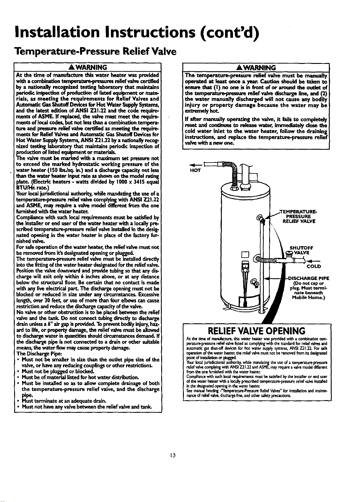
The tempe.ratere-pressorerelief valvemustbe installeddirectly
intothe fittingofthewaterheaterdesignatedforthe re,el valve.
Positionthevalvedownwardandprovidetubingsothat anydis-!
chargewill exit onlywithin6 inchesabove,or at anydistance
belowthe structuralfloor.Becertainthat no contactismadeI
with anyliveelectricalpart.The dischargeopeningmustnotbe
blockedor reducedin sizeunderanycircumstances.Excessive
length,over30 feet,or useof morethan fourelbowscancause
restriction andreducethe dischargecapacityofthevalve.
No valveor otherobstru_ionistobe placedbetweenthe relief
valveand the tank. Do not connecttubingdirectlyto discharge
drainunlessa 6"air gapisprovided.Topreventbodilyinjury,has-
arclto life,or propertydamage,the reliefvalvemustbeallowed
to dischargewater inquantitiesshouldcircumstancesdemand.If
the dischargepipeisnotconnectedto a drainor othersuitable
means,the waterflowmaycausepropertydamage.
The DischargePipe:
Mustnot be smallerin sizethan the outletpipesizeofthe
valve,or haveanyreducingcouplingsorotherrestrictions,
Mustnot be pluggedor blocked.
Mustbeofmateriallistedfor hotwaterdistribution.
Mustbe installedsoasto allowcompletedrainageof beth
the temperature-pressurerelief valve, and the discharge
pipe.
Mustterminateat anadequatedrain.
• Mustnothaveanyvalvebetweenthe reliefvalveandtank.
AWARNING
The temperature-pressure relief valve must be manually
operated ut leastonce a year. Caution shouldbe taben to
ensurethat (I) noone isin front ef or aroundthe outfotof
!the temper_ure-peessurereliefvalvedischargeline, and (2)
the water manually dischargedwill not causeany bodily
njury or property damage because the water may be
iextremelyhot
If after manually operating the valve, it failsto completely
iresetand continuesto releasewater, immediatelydose the
cold water inlet to the water heater, follow the draining
instructions,and replace the temperature-pressure relief
valvewltha newone.
,TEMPERATURE-
PRESSURE
RELIEF VALVE
SHUTOFF
[] VALVE
I COLD
PIPE
(Do not cap or
plug. Must termi-
nate beneath
Mobile Home.)
RELIEFVALVEOPENING
At thetimeof manufacture,thiswaterheaterwasproddedwitha combinationtem-
pe_tur_pressurereliefvahelistedascomplyingwiththestandardfor re,el_ and
automaticgasshot-offdevice_for hotwa_r supplysy_erns,ANSi791.22.For safe
operationofthewaterhe_t_ thereliefvalvemustnotberemovedfromitsdasillna_
pointofinstaiLatfunorp_ed.
YourIo_ judsdictfunalauthori_whilemandatir_theuseof atemperature-pressure
reliefvalvecomplyingwithANSI7.21.22andASMF_mayrequireavalvemodeldifferent
fromtheonefurnishedwiththewaterheater
Compliancewithsuchfucalrequirementsmustbesatisfiedbytheinstalleror enduser
ofthewaterheaterwithalocallyprescribedtempe_ture-pressurerellef_ahein_l_
inthedesignat_openinginthewaterheater.
Seemanualbeadin_-'Temperatu_*PressureP,eliefVahes for in_llationandmainte-
nanceofrelie_valve,dischargeline,andothersafe_precau_ons.
13
Installation Instructions (cont'd)
Filling the Water Heater
A CAUTION I
Neverusethiswator heetorunlessit B compietaiyfilledwith J
weter.To proventdamageto tbe tank,thetank m_-t betiltedJ
with water. Water must flow from the hot water faucet
beforeturning"ON" gastothe waterheator. I
To fillthe water heater with water:
• Close the water heater drain valve by turning the handle to
the right (clockwise). The drain valveis on the lower front of
the water heater.
• Oip_e cold water supply valve to the water heater.
NOTE, The cold water supply valve must be left open
when the water heater is in us_
• To insure complete filling of the tank, allow air to exit by
opening the nearest hot water faucet. Allow water to run
until a constant flow is obtained. This will let air out of the
water heater and the piping.
• Check all new water piping for leaks.Repairasneeded.
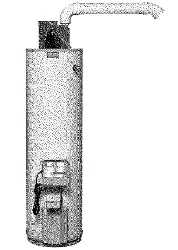
Venting
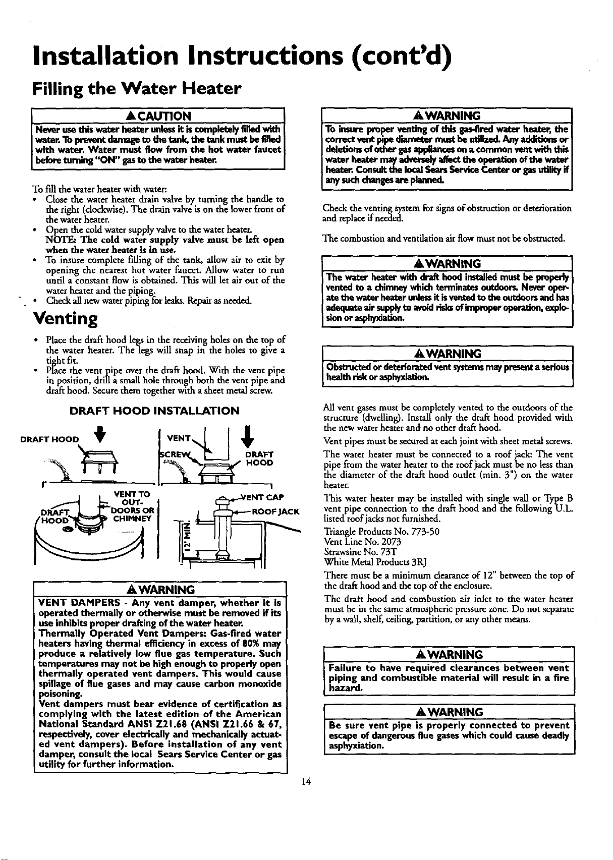
• Place the draft hood legs in the receiving holes on the top of
the water heater. The legs will snap in the holes to give a
tiv.ht fit.
• P['acethe vent pipe over the draft hood. With the vent pipe
in position, drill a small hole through both the vent pipe and
draft hood. Secure them together with a sheet metal screw.
DRAFT HOOD INSTALLATION
DRAFT HOOD t
A
/VENT . I;
/ VENT TO j !__L____ENi CAF
J=_ OUT-
DP_ET • _ DOORSOR _ _---ROOFJACK
HOOD CHIMNEY _;
AWARNING
VENT DAMPERS - Any vent damper, whether it is
operated thermally or otherwise must be removed if its
useinhibitsproper drafting ofthe water heater.
Thermally Operated Vent Dampers: Gas-fired water
heaters having thermal efficiencyin excessof 80% may
)roduce a relatively low flue gas temperature. Such
temperatures may not be high enough to properly open
thermally operated vent dampers. Thes would cause
spillage of flue gasesand may cause carbon monoxide
poisoning.
Vent dampers must bear evidence of certification as
complying with the latest edition of the American
National Standard ANSI Z21.68 (ANSI Z21.66 & 67,
respectively,cover electrically and mechanically actuat.
ed vent dampers). Before installation of any vent
damper, consult the local Sears Service Center or gas
utility for further information.
AWARNING
To insureproperventingof this gas-firedwater heater,the
correctventpipediametermustbeutilized.Anyadditions or
deledom ofothergasapplianceson acommon ventwith this
w-aterbeator may_ affect the operationoftheweter
heater.Consultthe localSearsServiceCanteror gasu_lityif
any,uchchangesaropkmn L
Check the venting system for signs of obstructionor deterioration
and replace ifneeded.
The combustion and ventilationair flow mustnot be obstructed.
&WARNING
The water heaterwith draft hoodinstalledmustbe properly
ventedto a chimneywhichterminatesoutdoorLNever oper-
atethewatsrheaterunlessit isventedtotheoutdoorsandhas
adequateair su.p_yto avoidrisksofimproperoperation,explo-
sionorasphyxiat_
• &WARNING
Obstructedor deterioratedventsystemsmaypresenta senousJ
healthriskor_. I
All vent gasesmust be completely vented to the outdoors of the
structure (dwe!ling). Insrall only the draft hood provided with
the new water heater and"no other draft hood.
Vent pipes must be secured at each joint with sheet metal screws.
The water heater must be connected to a roof iack: The vent
pipe from the water heater to the roof jack must be no less than
the diameter of the draft hood outlet (min. Y') on the water
heater.
This water heater may be installed with single wall or Type B
vent pipe connection to the draft hood and the following U.L.
listed roof jacks not furnished.
Triangle Products No. 773-50
Vent Line No. 2073
Strawsine No. 73T
White MetalProducts 3RJ
There must be a minimum clearance of 12" between the top of
the draft hood and the top of the enclosure.
The draft hood and combustion air inlet to the water heater
must be in the same atmosphericpressure zone. Do not separate
by awal!, shelf, ceiling, partition, orany other means.
AWARNING
Failure to have required clearances between vent
piping and combustible material will result in a fire
hazard.
. AWARNING J
Be sure vent pepe is properly connected to prevent
escapeof dangerousflue gaseswhich could causedeadly
asphyxiation.
14
Installation Instructions (cont'd)
Venting (cont'd)
AWARNING
Chemical vapor corrosion of the flue and vent system
may occur ifair for combustion containscertain chemlcai
vapors.Spraycanpropellants,cleaningsolvents, refrigera-
tor and air conditioner refrigerants, swimming pool
chemicals, calcium and sodium chloride, waxes bleach
and processchemicalsare typical compoundswhich are
potenti=lly corrosive.
Gas Piping
AWARNING
Make surethe gassuppliedisthe same type listedon the
imodelrating plate. The inlet gaspressuremust not exceed
14 incheswater column ½ poundper squareinch(3.5kPa).
iThe minimum inlet gaspressurelistedon the model rating
jplateisfor the purposeofinputadjustment.
_WARNING
If the gascontrolvalveissubjectedto pressuresexceeding ½I
pound per square inch(3.5klPa),the damageto the gascon-
tro valvecouldresult n afireor explosionfrom leakingga_
AWARNING
If the main gaslineshutoff servingall gasappliancesisused,
alsoturn "OFF" the gasat eachappliance.Leaveallgasappli-
ancesshutoffuntilthewater heaterinstallationiscomplete.
&WARNING
The applianceand its gasconnectionmust be leak tested
beforeplacingthe appliancemoperation.
&WARNING
• The applianceanditsindividualshutoffvalvemustbediscon-
nect_ fromthe gassupplypipingsystemduringanypressure
testingof the gassystemat test pressuresm excessof
persq=r*inch(3.Skh).
•Tbe appliancemustbe isolatedfromthegassupplypipingsys-
tem bydosingi_ individualmanualshutoff valveduring
pressuretestingofthe gassupplypipingsystemat testpres-
suresequalorlessthan'/2poundpersquareinch(].SkPa).
AWARNING I
Use pipejoint compoundor teflon tape marked as beingJ
Lresistantto theactionof petm eumlet°pane (LR)] gases" ...J
A gas line of sufficient size must be run to the water heater.
Consult the latest edition of National Fuel Gas Code ANSI
Z223.1 also referred to _ NFPA54 and the gas company concern-
ing pipe size,
There must be:
I A readily accessiblemanual shut offvalve in the gas supply line
serving the water heater, and
A drip leg (sediment trap) aheadof the gas control valveto help
prevent dirt and foreign materials from entering the gas control
Valve,
• A flexible gas connector or a ground joint union between the
shutoffvalve and control valve to permit servicing ofthe unit.
Be sure to check all the gas piping for leaks before lighting the
water beater. Use a soapy water solution, not a match or open
flame. Rinseoffsoapy solution and wipe dry.
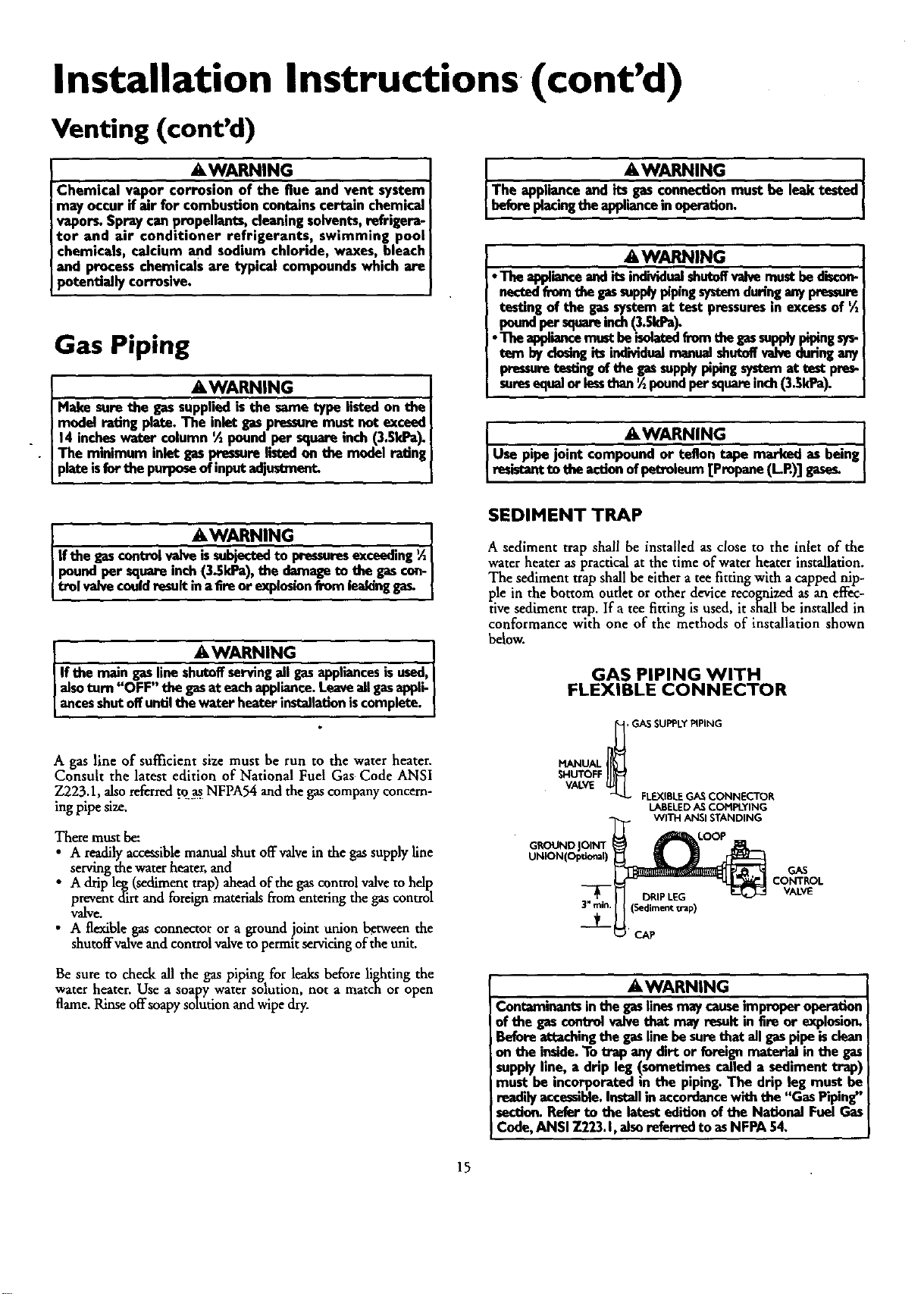
SEDIMENT TRAP
A sediment trap shall be installed as close to the inlet of the
water heater as practical at the time of water heater installation.
The sediment trap shall be either atee fitting with a capped nip-
ple in the bottom outlet or other device recognized as an effec-
tive sediment trap. If a tee fitting is used, it shall be installed in
conformance with one of the methods of installation shown
below.
GAS PIPING WITH
FLEXIBLE CONNECTOR
_H, GAS SUPPLYPIPING
MANUAL
SHUTOFF
VALVE
FLEXIBLEGASCONNECTOR
LABELED AS COMPLYING
WITH ANSI STANDING
GROUND
GAS
CONTROL
VALVE
AWARNING
Contaminants in thegasfinesmaycauseimproperoperation
of the gascontrolvalvethat may resultin Ereor explosion.
Beforeattachingthe gaslinebesurethat allgaspipeisclean
on the inside.To trap anydirt or foreignmaterial in the gas
supplyllne, a drip leg (sometimescalleda sediment trap)
mu_ be incorporated in the piping.The drip leg must be
readilyaccessible.Installinaccordancewith the "Gas Piping"
section.Referto the latesteditionof the Na_onal FuelGas
Cede,ANSI 7.223.1,alsoreferredto asNFPA54.
15
Installation Instructions (cont'd)
"Fuel" Conversion Instruc-
tions From Natural Gas To
Propane (L.P.) Gas
&WARNING
This water heater hasbeen factory equipped to operate
with the type gasindicatedin the "EQUIPPED FOR" area
of the model rating plate located near the gas control
valve. The indicated gas may be either Natural or
Propane (L.R). Byfollowingthe conversioninstructionsin
this manual or the instructionsnear the gascontrol valve,
the water heater must be converted if it is to be used
with the opposite gas. DO NOT USE THIS WATER
HEATER WITH ANY GAS OTHER THAN THE ONE
LISTED ON THE MODEL RATING PLATE. Failureto use
the correct gas can cause problems which can result in
DEATH, SERIOUS BODILY INJURY, OR PROPERTY
DAMAGE. If you have any questions or doubts consult
your gassupplieror gascompany.
Read and follow detailed conversion instructions located on the
water heater and also in this manual in their entirety before starting
the conversion.
Conversion kit with necessary parts are in a bag attached to the
drain valve.
Step 1.
Step 2.
Step 3.
Step 4.
Step 5.
Turn gascontrol knob "A"to "PILOT". Depress and turn
"OFF. (See Figure 1, page 17).
Remove outer and inner accessdoors from water heater.
Removeburner as_,mbly from water heater and control by
loosening _Anut H holding burner assembly to control.
(See Figure 2, page 17). Loosen pilot tube nut _J" and
thermocouple nut "K" at control.
Remove screws _D" disengaging manifold from burner.
(See Figure 3, page 17)
Remove orifice _E" (See Figure 3, page 17) using 3A"
wrench. Install orifice marked _L.P." found in the bag
into manifold. Tighten securely. Secure burner to mani-
fold with screwsSD '.
Step 6. Loosen pilot tube nut "F" (See Figure 4, page 17). Re-
move orifice "G" and replace with blue colored orifice
found in bag. Reinstall nut "F" and tighten securely.
Step 7. Makesure all connections are tightened securely,and rein-
stall burner assemblyinto waterheater. Position end of the
manifold inside bracket as shown in Figure3 on page 17.
Reinstall manifold into control andtighten 3A"nut ("H')
securely. Recheck to see that end of tuanifold is still inside
bracket as shown in Figure 3 on page 17. Reinstall pilot
tubing and thermocouple into control. (See Figure 2,
page 17)
Step 8. Place screwdriver in slot _B'. (See Figure 1, page 17). De-
press and turn counter-clockwise (_-'_) to stop. Con-
trol screw must be in "IN" position for propane (UE) gas
and m OUT posmon for natural gas. STOP. Readlabel
"For Your Safety" located on your water heater.
Step 9.
Step 10.
Step 1I.
Step 12.
Step 13.
Step 14.
Step 15.
Step 16.
Step 17.
Step 18.
Step 19.
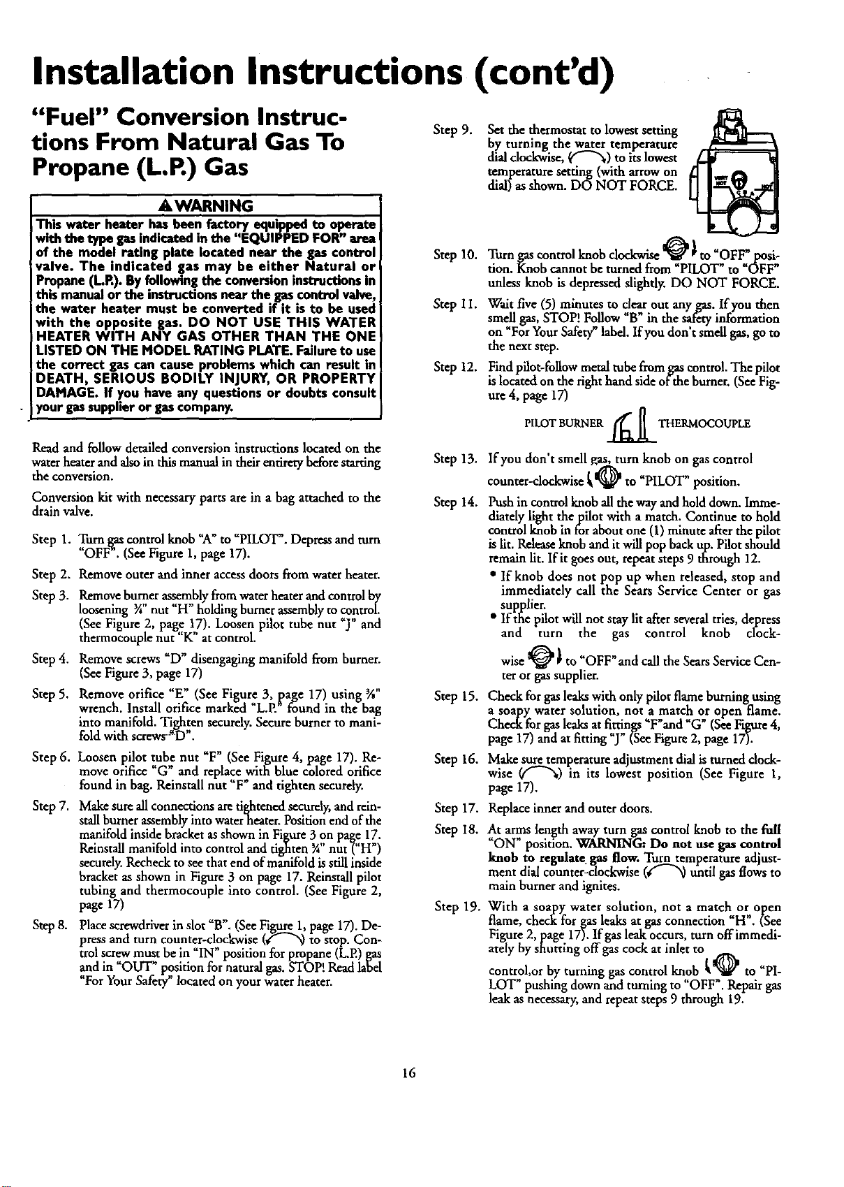
Set the thermostat to lowest setting
by turning the water temperature
dial clockwise, ("-'_) to its lowest
temperature setting (with arrowon
dial) asshown. DO NOT FORCE.
Turn gas control knob clockwise _ _to _OFF_,._:_si-
tion. Knob cannot be turned from PILOT"to OFF"
unless knob is depressed slightly. DO NOT FORCE.
Wait five (5) minutes to dear out any gas. If you then
smell gas, STOP! Follow _B" in the safety information
on "ForYourSafety" label. If you don't smell gas, go to
the next step.
Find pilot-follow metal tube from gas control. The pilot
is locatedon the right hand side of the burner. (See Fig-
ure 4, page 17)
PILOT BURNER ___ THERMOCOUPLE
If you don't smell gas, turn knob on gas control
counter-clockwise __ to _PILOT" position.
Push in control knob allthe way andhold down. Imme-
diately light the pilot with amatch. Continue to hold
control knob in for about one (1) minute afterthe pilot
is lit. Releaseknob and it will pop back up. Pilot should
remain lit. If it goes out, repeat steps 9 through 12.
• If knob does not pop up when released, stop and
immediately call the Sears Service Center or gas
supplier.
• If the pilot will not stay lit afterseveral tries, depress
and turn the gas control knob clock-
wise _ _ to "OFF"and call the SearsService Cen-
ter or gas supplier.
Check for gas leakswith only pilot flame burning using
a soapy water solution, not a match or open flame.
Cbeck for gas leaksat fittings_F_and _G_(SeeFigure4,
page 17) and at fitting _J" (See Figure2, page 17).
Make sure temperature adjustment dial is turned dock-
wise (f'-'%) in its lowest position (See Figure 1,
page 17).
Replaceinner and outerdoors.
At arms length away turn gas control knob to the full
ON position. WARNING: Do not use gas control
knob to regulate gas flow. Turn temperature adjust-
tuent dial counter-clockwise (_"x) until gas flows to
main burner andignites.
With a soapy water solution, not a match or open
flame, check for gas leaks at gas connection "H'. (See
Figure 2, page 17). If gas leak occurs,turn offimmedi-
ately by shutting offgas cock at inlet to/a,._
control,or by turning gas control knob sh'_ to PI-
LOT" pushing down and turning to "OFF ". Repair gas
leak as necessary, and repeat steps 9 through 19.
16
Installation Instructions (cont'd)
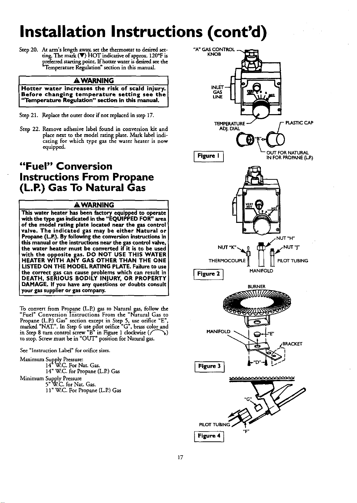
Step 20. At arm's length away,set the thermostat to desired set-
ting. The mark _ HOT indicative of approx.120°F is
LP,,referredstarting pint. If hotter water is desiredseethe
Temperature Regulation section in this manual.
"A" (
KNOB
AWARNING
Hotter water increases the risk of scald inlury.
Before changing temperature setting see the
"Temperature Regulation" section in this manual.
GAS
UNE
Step21. Replace the outer door ifnot replaced in step 17.
Step 22. Remove adhesive label found in conversion kit and
place next to the model rating plate. Mark label indi-
cating for which type gas the water heater is now
equipped.
"Fuel" Conversion
Instructions From Propane
(L.P.) Gas To Natural Gas
TEMPERATURE it- PLASTICCAP
ADJ.DIAL ,,
"_--o_ _R NATURAL
[ Figure I ] IN FOP,PROPANE(LR)
AWARNING
This water heater has been factory equipped to operate
with the type gasindicated in the "EQUIPPED FOR" area
of the model rating plate located near the gas control
valve. The indicated gas may he either Natural or
Propane (LR). Byfollowingthe conversioninstructionsin
this manualor the instructionsnear the gascontrolvalve,
the water heater must he converted if it is to he used
with the opposite gas. DO NOT USE THIS WATER
HEATER WITH ANY GAS OTHER THAN THE ONE
LISTED ON THE MODEL RATING PLATE. Failureto use
the correct gascan cause problems which can result in
DEATH, SERIOUS BODILY INJURY, OR PROPERTY
DAMAGE. If you have any questions or doubts consult
yourgassupplieror gascompany.
To convert from Propane (L.P.) gas to Natural gas, follow the
"Fuel" Conversion Iristructions From the =Natural Gas to
Propane (LP.) Gas" section except in Step 5, use orifice "E",
marked "NAT.". In Step 6 use pilot orifice "G", brass color and
in Step 8 turn control screw "B_"in Figure 1 clockwise (f-"%)
to stop. Screw must be in "OUT" position for Natural gas.
See =Instruction Label" for orifice sizes.
Maximum Supply Pressure:
14"W.C. For Nat. Gas.
14" W.C. for Propane (L.E) Gas
Minimum Supply Pressure
5"W.C. for Nat. Gas.
11" W.C. For Propane (L.E) Gas
NOT "H"
THERHOCOUPLE ][ L_ LL PILOT TUBING
IF,guru2} N,FOLO
BURNER
,
PILOT TUBING'_ _
I Figure 41 "F"
17
Installation Instructions (cont'd)
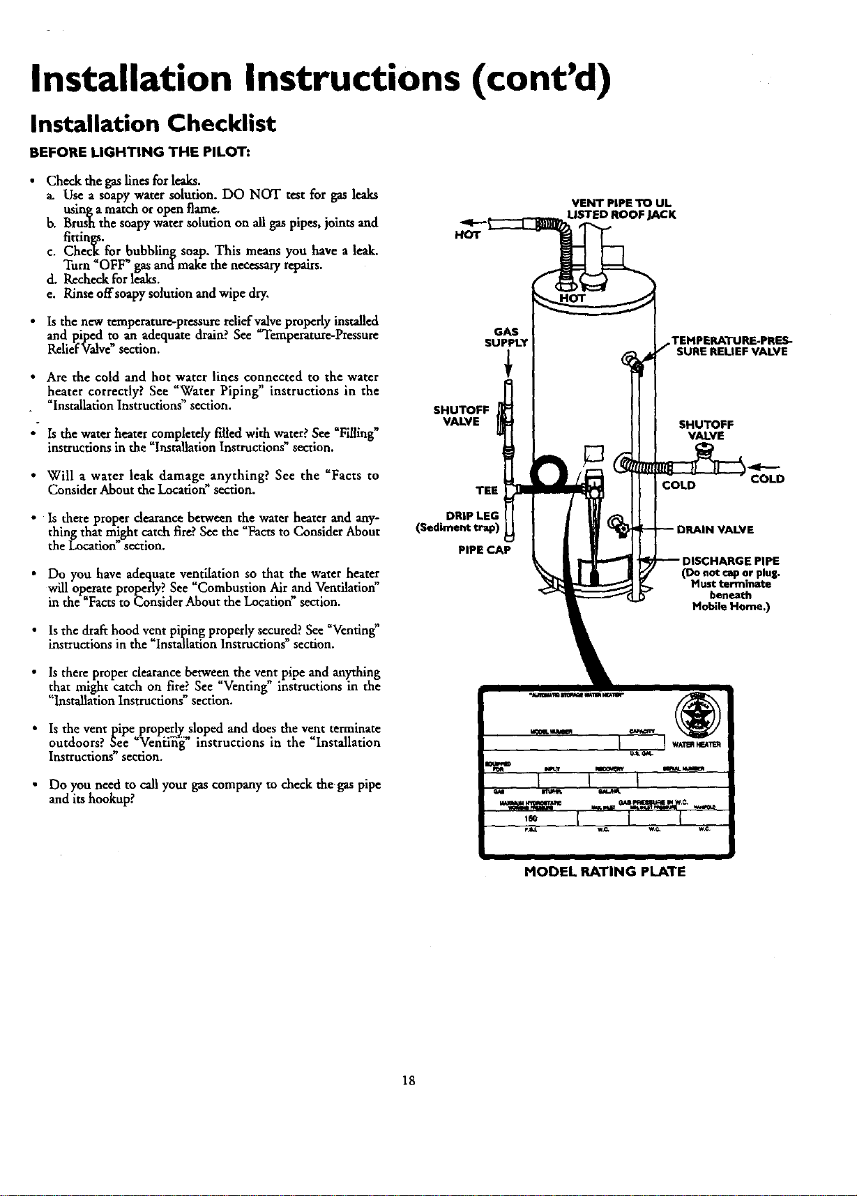
Installation Checklist
BEFORE LIGHTING THE PILOT:
• Check the gaslines for leaks.
_. Use a soapy water solution. DO NOT test for gas leaks
usinga match or open flame.
b. Brush the soapy water solution on all gas pipes, joints and
fimngs.
c. Check, for bubbling soap. This means you have a leak.
Turn OFF gasand make the necessary repairs.
d. Recheck for leaks.
e. Rinse offsoapy solution and wipe dry,
• Is the new temperature-pressnse relief valye properly installed
and piped to an adequate drain?See Temperature-Pressure
ReliefValve section.
• Are the cold and hot water lines connected to the water
heater correctly? See _Water Piping" instructions in the
"Installation Instructions" section.
• Is the water heater completely filled with water. See Pi/hng
instructions in the "Installation Instructions _section.
• Will a water leak damage anything? See the "Facts to
Consider About the Locatio_ section.
• Is there proper dearance between the water heater and any-
thing that might catch fire?See the "Facts to Consider About
the Location" section.
• Do you have adequate ventilation so that the water heater
will operate properly? See Combustion Air and Ventilation
in the "Facts to Consider About the Location_section.
Is the drafthood vent piping properly secured? See "Venting"
instructions in the "Installation Instructions" section•
HOT
GAS
SUPPLY
SHUTOFF
VALVE
DRIP LEG
(Sediment trap)
PIPE CAP
VENT PIPE TO UL
LISTED ROOF JACK
TEMPERATURE-PRES-
SURE RELIEF VALVE
SHUTOFF
VALVE
COLD COLD
DMonot cap or plus.
ust terminate
beneath
Mobile Home.)
Is there proper clearance between the vent pipe and anything
that might catch on fire_ See Venting instructions in the
"InstallationInstructions section•
• Is the vent pipe properlE sloped and does the vent terminate
outdoors? See "Venii_g" instructions in the "Installation
Instrucuons section,
• Do you need to call your gas company to check the gas pipe
and its hookup?
MODEL RATING PLATE
18
Operating Instructions
Lighting
AWARNING
BEFORE LIGHTING [PROPANE (L.R) GAS WATER
HEATERS]:Propane(LR) gasisheav_ thanair,Shouldthere
bea leak in the system, the gaswill settlenear the ground.
Basements,crawlspaces,skirtedareasunder mobile homes
(evenwhenvenl_la_, dosutsandareasbelowgroundlev_will
serveas pockets for the accumulationof this gas. Before
attemptingto ligl_,or relight_ waterheater'spilotor turning
on a nemaoyelectrlcalli_t_'€switch,beabsulutdysumthemisno
accumulatedgasint_ are_ Searchfor odorofgasbym'dfingat
groundlevelinthevicinityoftbeappliance.Ifodorisdetected,
followstepsindicatedat "For YourSafety"onthecoverpageof
thismanualthenleavethepremises.
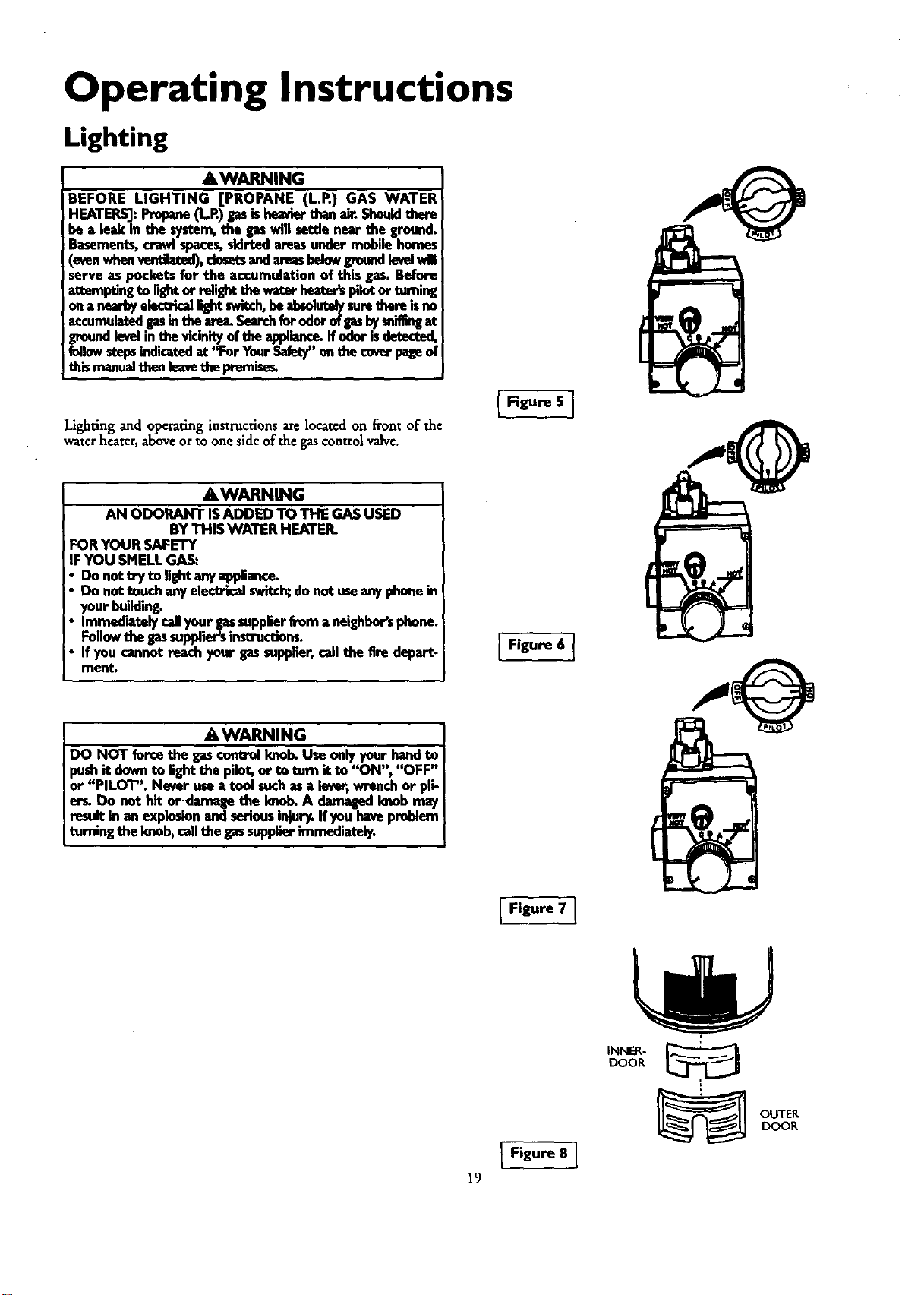
Lighting and operating instructions arelocated on front of the
water heater, above orto one side of the gas control valve.
Figure 5 ]
AWARNING
AN ODORANT ISADDED TO THE GASUSED
BY THIS WATER HEATER.
FOR YOUR SAFETY
IF YOU SMELl.GAS:
Do not try to lightanyapplie_.e.
Do not touch anyelectrlcalswitch;do not useanyphonein
yourbuilding.
Immediatelycallyourgassupplierfrom aneighbor'sphone.
Follow the gassuppliersinstructions.
If you cannotreachyour gassupplier,call the fire depart.
merit.
Figure 6 ]
AWARNING
DO NOT forcethe gascontrolknob.Useonly yourhandto
pushit downto lightthe pilot,or to turn it to "ON", "OFF"
or "PILOT". Never usea tool suchasa lever,wrenchor pli-
er_ Do not hit or damage the knob.A damagedknobmay
result in anexplosionandseriousinjury,ffyou haveproblem
turningtheknob, callthe gassupplier immediately.
19
Figure 7 ]
I Figure 8 ]
INNER- ._
DOOR
_ UTER
DOOR
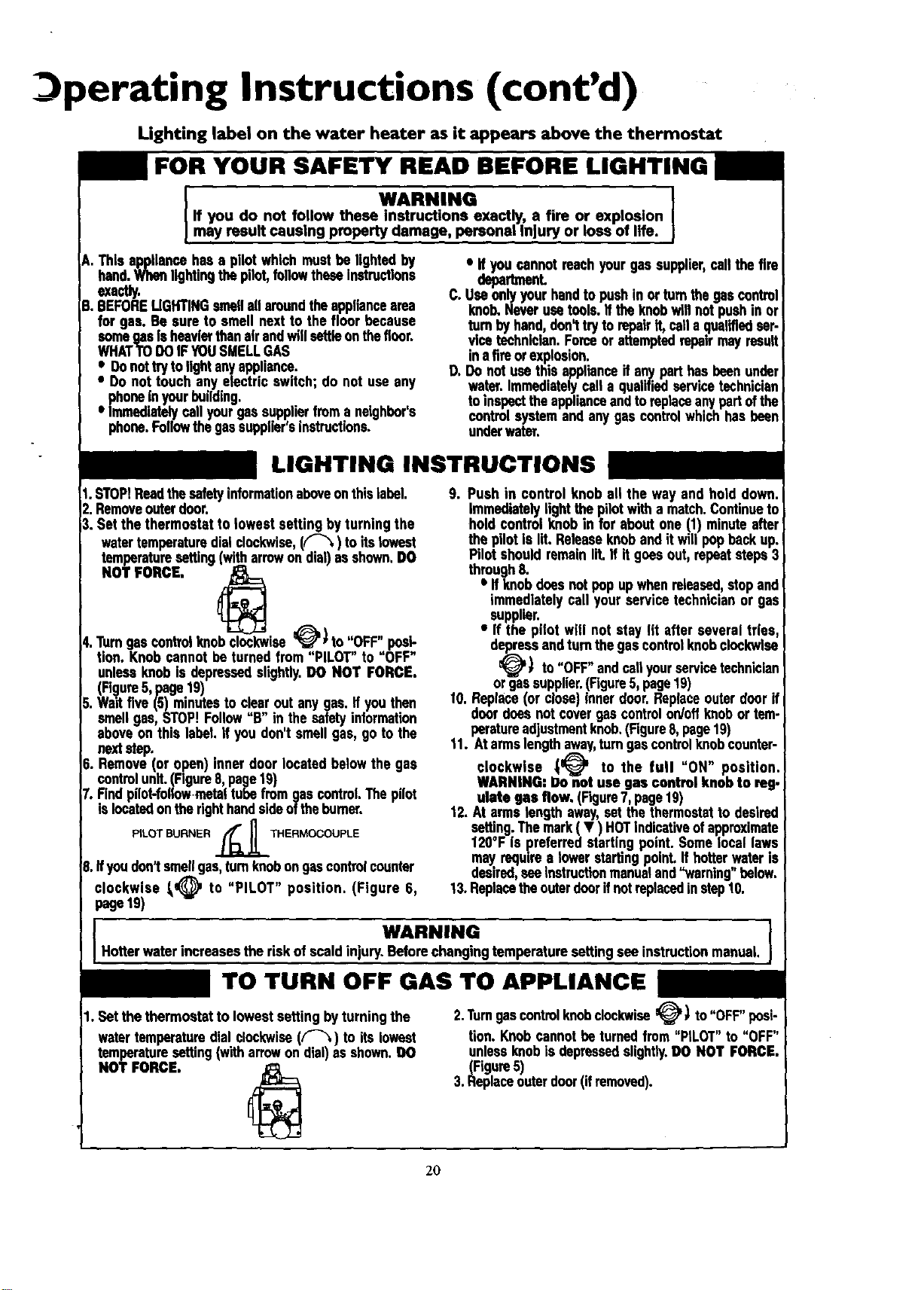
perating Instructions (cont'd)
Lighting label on the water heater as it appears above the thermostat
FOR YOUR SAFETY READ BEFORE LIGHTING
WARNING J
If you do not follow these Instructions exactly, a fire or explosion
may resu t causing property damage, personal njury or ose of life.
A. Thisappliancehasa pilot whichmustbe lightedby
hand.Whenlightingthepilot,followtheseInstructions
exactly.
g. BEFORELIGHTINGsmellallaroundtheappliancearea
for gas. Be sure to smell nextto the floor because
somegasIsheavierthanairandwillsettleonthericer.
WHATTODOIFYOUSMELLGAS
eeeDonottrytolightanyappliance.
Do not touch anyelectric switch; do not useany
phoneInyourbuilding.
Immediatelycall yourgassupplierfroma neighbor's
phone.Followthegassupplier'sinstructions.
• If youcannotreachyourgassupplier,cellthe fin
depeth_nL
C. Useonlyyour handtopushin orturnthegascontrol
knob.Neverusetools.If theknobwillnotpushin or
turnbyhand,don_tryto repairIf, calla qualifiedser-
vicetechnician.Forceor attemptedrepairmay result
inatimorexplneion.
D. Donot usethisapplianceif anypart hasbeenunder
water.Immediatelycell a qualifiedservicetechnician
toinspecttheapplianceandtoreplaceanypartofthe
central systemand anygascontrolwhichhasbeen
underwater.
LIGHTING INSTRUCTIONS
1.STOPIReadthesafetyinformationaboveonthislabel.
2.Removeouterdoor.
3. Set the thermostatto lowest settingbyturning the
watertemperaturedialclockwise,(F'_) to itslowest
temperaturesetting (witharrowon dial)asshown,DO
NOT FORCE,
4.Turngascentrul knobclockwise_J'* to "OFF" posi-
tion. Knob cannotbeturnedfrom "PILOT" to "OFF"
unlessknobIs depressedslightly.DO NOT FORCE.
(Fi(_lure5,page 19)
5. Waitfive(5) minutesto clearout anygas. ifyou then
smellgas, STOP!Follow"B" in thesafetyinformation
aboveon this label If you don'tsmellgas, go tothe
nextstep.
6. Remove(or open)inner door locatedbelowthe gas
controlunit.(Figure8,page19)
7. Rnd pilot-followinstaltubefromgascontrolThepilot
s ocatedonthe rghthands deoftheburner.
PILOT BURNER ._THERMOCOUPLE
8,Ifyoudon1smellgas,turnknobongascontrolcounter
clockwise _@ to "PILOT" position. (Figure 6,
page19)
9. Push in control knoball the way and hold down.
Immediatelylightthepilotwitha match.Continueto
holdcontrolknobin for aboutone (1) minuteafter
the pilotis lit. Releaseknoband itwillpopbackup.
Pilotshouldremainlit.If it goesout,repeat steps3
through8.
• Ifknobdoesnotpop upwhenreleased,stopand
immediatelycall yourservicetechnicianor gas
supplier.
• If the pilot will not stay lit afterseveral tries,
depressandturnthegascontrolknobclockwise
_) to "OFF"andcallyourservicetechnician
orgassupplier.(Figure5,page19)
10. Replace(or close)innerdoor.Replaceouterdoorif
doordoesnot covergascontrolon/offknobor tem-
peratureadjustmentknob.(Figure8,page19)
11. Atarmslengthaway,turngascontrolknobcounter-
clockwise _ to the full "ON" position,
WARNING: Do not use gas control knobto reg.
ulate gas flow. (Figure7, page19)
12.At armslengthaway,setthe thermostatto desired
setting. Themark( • ) HOTindicativeofapproximate
120°F Is preferredstarting point.Somelocal laws
mayrequires towerstarting"point. If hotter.,,wateris
desired,seeinstructionmanualand"warning below.
13.Replacetheouterdoorifnotreplacedinstep10.
WARNING
Hotterwaterincreasesthe riskof scaldinjury.Beforechangingtemperaturesettingsee instructionmanual.
TO TURN OFF GAS TO APPLIANCE
1. Setthe thermostatto lowestsettingbyturningthe
watertemperaturedialclockwise(F-_) to itslowest
temperaturesetting(witharrowondial)as shown.DO
NOT FORCE.
2.Turngascontrolknobclockwise_' _ to"OFF"posi-
tion.Knobcannotbe turnedfrom"PILOT"to "OFF"
unlessknobis depressedslightly.DO NOT FORCE.
(Figure5)
3.Replaceouterdoor(ifremoved).
2O
Operating Instructions (cont'd)
Temperature Regulation
Due to the nature of the t,!pical gas water heater, the water tem-
_oerature in certain situauons may vary up to 30°F higher or
wet at the point of use such as, bathtubs, showers, sink, etc.
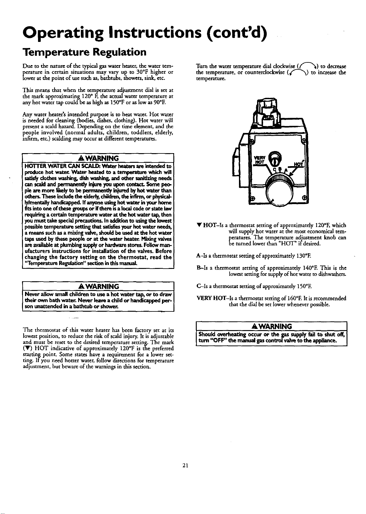
Turn the water temperature dial dockwise (f"-_) to decrease
the temperature, or counterdoc.kwise (4 f _"_) to increase the
temperature.
This means that when the temperature adjustment dial is set at
the mark approximating 120° F, the actualwater temperature at
any hot water tap could be as high as 150°F or as low as90°E
Any water heater's intended purpose is to heat water. Hot water
is needed for cleaning (bodies, dishes, clothing). Hot water will
present ascald hazard. Depending on the time element, and the
people involved (normal adults, children, toddlers, elderly,
infirm, etc.) scalding may occur atdifferenttemperatures.
a,WARNING
HOTTERWATERCAN SCALD:.Water heatersareintendedto
producehot water.Water heatedto a temperaturewhichwill
satisfyclotheswashing,dishwashing,andothersanitizingneeds
canscaklandpermaneutlyinjureyouupon€ontact.Somepeo-
plearemorelikelyto bepermanentlyinjured_ hotwaterthan
other_Theseincludetheelderly,children,theinfirm,or physicag
ly/mentellyhandicapped.If anyoneusinghotwaterinyourhome
fitsintooneofthesegroupsor ifthereisa localcedeor statelaw
requiringacertaintemperaturewaterat thehotwater_ then
_)umusttakespeci_Jprecautlon_In additionto usingthelowest
)ossibletemperature.se_ngthatsatisfiesyourhotwaterneeds,
tmeanssuchasa mixingvalve,shouldbeusedat thehotwater
tapsusedbythese peopleor at thewaterheater.Mixingvalves
areavailableat plumbingsupplyor hardwarestoreLFollowman-
ufacturersinstructionsfor installationof the valves.Before
changingthe factory setting on the thermostat, read the
'_l"emperatureRegulation"sectioninthismanual.
AWARNING !
Never allowsmallchildrento usea hot water tapsor to draw I
theirownbathwater. Neverleavea childor handicappedper- I
I sonunattendedina bathtubor shower. I
• HOT-Is a thermostat setting of approximately 120°F, which
will supply hot water at the most economical tem-
[eratures. The tempe,,_ture adjustment knob can
e turned lower than HOT" if desired.
A-Is a thermostat setting of approximately 130°E
B-Is a thermostat setting of approximately 140°E This is the
lowest setting for supply ofhot water to dishwashers.
C--Is a thermostat setting of approximately 150°E
VERY HOT-Is a thermostat setting of 160°E It is recommended
that the dial be set lower whenever possible.
The thermostat of this water heater has been factory set at its
lowest position, to reduce the risk of scald injury. It is adjustable
and must be reset to the desired temperature setting. The mark
(•) HOT indicative of approximately 120°F is the preferred
starting point. Some states have a requirement for a lower set-
ting. If you need hotter water, follow directions for temperature
adjustment, but beware of the warnings in this section.
AWARNING
Shouldoverheatingoccuror the gassupplyfail to shut off,
tum "OFF themanualgascontrolvalveto theappliance.
21
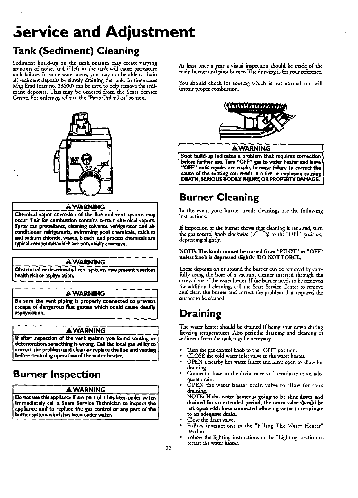
Service and Adjustment
Tank (Sediment) Cleaning
Sediment build-up on the tank bottom may create varying
amounts of noise, and if left in the tank will cause premature
tank failure. In some water areas, you may not be able to drain
all sediment deposits by simply draining the tank. In these cases
Mag Erad(part no. 23600) can be used to help remove the sedi-
ment deposits. This may be ordered from the Sears Service
Center. For ordering, referto the Parts Order List section.
At least once ayear a visual inspection should be made of the
main burner and pilot burner. The drawing is for your reference.
You should check for sooting which is not normal and will
impair proper combusdon.
. . . &WARNING I
] Soot budd-upindicatesa problemthat requires correction
I beforefurther use.Turn'_DFF"gasto waterheaterandleave
}'_FF" untilrepairsare made,becausefailureto correct
causeof the sootingcanresultin a Ere or explosioncuumng
I DEATH,SERIOUSBODILYINJURY,ORPROPERTYDAMAGE
&WARNING
Chemicalvapor corrosionofthe flue andvent systemmay
occurif air for combustion containscertainchemir.alvapor_
Spraycan propellants,cleaningsolvents,refrigerator and air
conditionerrefrigerants, swimmingpoolchemicals,calcium
andsodiumchloride,waxes,bleach,andprocesschemicalsare
typicalcompoundswhicharepotentiallycorrns'n_.
#`WARNING I
Obstructed ordeterioratedventsystemsmaypresentaserious
healthriskor asphyxiat_n. I
I AWARNIHG I
Be sure the vent pip_onnected to prevent
escapeof dangerousflue gasseswhich could causedeadly[
aspMxla6on, I
#'WARNING ]
if after inspectionof the vent systemyou found sootingor I
deterioration,somethingiswrong.Callthe localgasutilityto |
correctthe problem_ dean or replacetheflueandventing}
beforeresuming operationof the water heater. ]
Burner Inspection
#`WARNING ]
Do not_ this applian_ hasbeenunderwater.|
Immediately calla SearsService Technicianto inspectthe |
applianceand to replace the gascontrolor any part of the |
burnersystemwhichhasbeenunderwater. ]
22
Burner Cleaning
In the event your burner needs cleaning, use the following
instructions:
If inspection of the burner shows that denning is reouired, turn
the gas control knob clockwise (_ to the _OFI_ position,
depressing slightly.
NOTE: The knob cannot be turned from "PILOT" to "OFF"
unless knob is depressed slightly_DO NOT FORCE.
Loose deposits on or around the burner can be removed by care-
fully using the hose of a vacuum deaner inserted through the
access door of the water heater. If the burner needs to be removed
for additional cleaning, call the Sears Service Center to remove
and clean the burner and correct the problem that required the
burner to be cleaned,
Draining
The water heater should be drained if being shut down during
freezing temperatures. Also periodic draining and cleaning of
sediment from the tank may be necessary.
Turn the gascontrol knob to the _OFF" position,
CLOSE the cold water inlet valve to the water heater.
OPEN a nearby hot water faucet and leaveopen to allow for
draining.
Connect a hose to the drain valve and terminate to an ade-
quate drain.
OPEN the water heater drain valve to allow for tank
draining.
NOTE: If the water heater is going to be shut down and
drained for an extended period, the drain valve should be
left open with hose connected allowing water to terminate
to an adequate drain.
Close the drainvalve.
Follow instructions in the "FiUing The Water Heater"
section.
Follow the lighting instructions in the ULighting" section to
restartthe water heater.
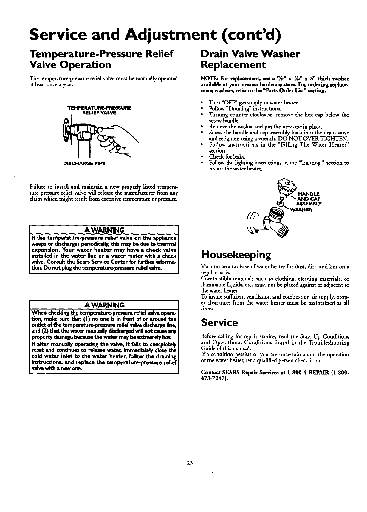
Service and Adjustment (cont'd)
Temperature-Pressure Relief
Valve Operation
The temperature-pressure relief valve must be manually operated
at least once a y_ar.
Drain Valve Washer
Replacement
NOTE: For replacement, use a '_" x _," x %" thick washer
available at your nearest hardware stem For o_lering t_-place-
me_t washer_ refer m the "Parts Order List_ section.
TEMPERATURE-PRESSURE
RELIEF VALVE
DISCHARGE PIPE
• Turn "OFF *gassupply to water heater.
Follow "Draiuing _instructions.
Turning counter dockwise, remove the hex cap below the
screw handle.
• Remove the washer and put the new one in place.
Screw the handle and cap assembly back into the drain valve
and retightenusing a wrench. DO NOT OVER TIGHTEN;
• Follow instructions in the Filling The Water Heater
section.
• Check for leaks.
• Follow the lighting instructions in the "Lighting" section to
restart the water heater.
Failure to install and maintain a new properly listed tempera-
ture-pressure relief valve will rdease the manufacturerfrom any
claim which might result from excessivetemperature orpressure.
AWARNING
If the temperature-pressure relief valve on the appliance
weepsor dischargesperiodically,this may be dueto thermal
expansion. Your water heater may have a check valve
installed in the water line or a water meter with a check
valve.Consultthe SearsServiceCenter fur further informa-
tion. Do not plugthetemperature-pressurerelief valve.
A WARNING
When checkingthe temperature-pressurereliefvalveopera-
tion, make surethat (I) no one is in front of or aroundthe
outletoftbe _perature-pr_sure relief valve dischar_ line,
and(2) thatthe water manually_ willnot causuany
propertydamagebecametbewater maybeextremeS/hot.
If after manually operating the valve, it failsto completely
reset and continuesto releasewater, immediatelyclosethe
coldwater inlet to the water heater, follow the draining
instructions,and replace the temperature-pressure relief
valve with a now one.
A$SEHBLY
Housekeeping
Vacuum mound base of water heater for dust, dirt, and lint on a
regular basis.
Combustible materials such as clothing, cleaning materials, or
flammable liquids, etc. must not be placed againstor adjacent to
the water heater.
To insure sufficient ventilation and combustion air supply, prop-
er clearances from the water heater must be maintained at all
times.
Service
Before calling for repair service, read the Start Up Conditions
and Operational Conditions found in the Troubleshooting
Guide of this manual.
If a condition persists or you are uncertain about the operation
of the water heater, let a qualified person check it out.
Contact SEARS Repair Services at 1-800-4-REPAIR (1-800-
473-7247).
23
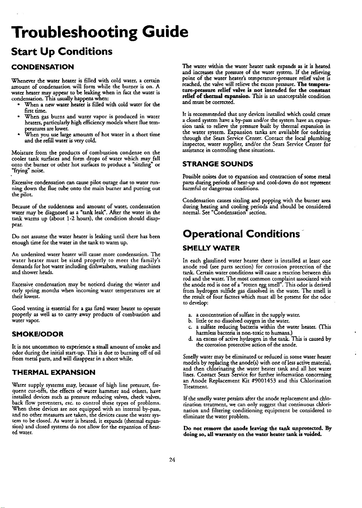
Troubleshooting Guide
Start Up Conditions
CONDENSATION
Whenever the water heater is filled with cold water, a certain
amount of condensation will form while the burner is on. A
water heater may appear to be leakingwhen in fact the water is
condensation. This usually happens when:
• When a new water heater is filled with cold water for the
first time.
When gas burns and water vapor is produced in water
heaters, particularly high efficiency models where flue tem-
peratures are lower,
When you use large amounts of hot water in a short time
and the refill water is very cold.
Moisture from the products of combustion condense on the
cooler tank surfaces and form drops of water which mxy fall
onto the burneror other hot surfaces to produce a _sizzling or
"frying" noise.
Excessivecondensation can cause pilot outage due to water run-
ning down the flue robe onto the main burner and putting out
the pilot.
Because of the suddenness and amount of water, condensation
water may be diagnosed as a "tank leak". After the water in the
tank warms up (about 1-2 hours), the condition should disap-
pear.
Do not assume the water heater is leaking until there has been
enough time for the water in the tank to warm up,
An undersized water heater will cause more condensation. The
water heater must be sized properly to meet the family's
demands for hot water including dishwashers, washing machines
and shower heads.
Excessive condensation may be noticed during the winter and
early spring months when incoming water temperatures are at
their lowest.
Good venting is essential for a gas fired water heater to operate
properly as well as to carry away products of combustion and
water vapor.
SMOKEIODOR
It is not uncommon to experience a small amount of smoke and
odor during the initial start-up. This is due to burning off of oil
from metal parts, and will disappear in a short while.
THERMAL EXPANSION
Water supply systems may, because of high line pressure, fre-
quent cut-offs, the effects of water hammer and others, have
installed devices such as pressure reducing valves, check valves,
back flow preventers, etc. to control these types of problems.
When these devices are not equipped with an internal by-pass,
and no other measures are taken, the devices cause the water sys-
tem to be closed. As water is heated, it expands (thermal expan-
sion) and dosed systems do not allow for the expansion of heat-
ed water.
The water within the water heater tank expands as it is heated
and increases the pressure, of the water system. If the relieving
point of the water heaters temperature-pressure relief valve is
reached,the valve will relieve the excesspreSSure.The tempm'a-
tu_-pressure relief valve is not intended for the constant
re.lid"of thermal expansson. This is an unacceptable condition
and must be corrected.
It is recommended that any devices installed which could create
a dosed system have a by-pass and/or the system have an expan-
sion tank to relieve the pressure built by thermal expansion in
the water system. Expansion tanks are available for ordering
through the Sears Service Center. Contact the local plumbing
inspector, water supplier, and/or the Sears Service Center for
asststance in controlling these situations.
STRANGE SOUNDS
Possible noises due to expansion and contraction of some metal
parts during periods of heat-up and cool-down do not represent
harmful or dangerous conditions.
Condensation causes sizzling and popping with the burner area
during heating and coolin[g periods and should be considered
normal. See "Condensation section.
Operational Conditions
SMELLY WATER
In each glasslined water heater there is installed at least one
anode rod (see parts section) for corrosion protection of the
tank. Certain water conditions will cause a reaction between this
rod and the water, The most common complaint associated with
the anode rod is one of a "rotten egg smell . This odor is derived
from hydrogen sulfide gas dissolved in the water. The smell is
the result of four factors which must all be present for the odor
to develop:
a. a concentration of sulfate in the supply water.
b. little or no dissolved oxygen in the water.
c. a sulfate reducing bacteria within the water heater. (This
harmless bacteria is non-toxic to humans.)
d. an excess of activehydrogen in the tank. This is caused by
the corrosion protective actionof the anode.
Smelly water may be eliminated or reduced in some water heater
models by repladng the anode(s) with one of less activematerial,
and then chlorinating the water heater tank and all hot water
lines. Contact Sears Service for further information concerning
an Anode Replacement Kit #9001453 and this Chlorination
Treatment.
If the smelly water persists after the anode replacement and chlo-
rination treatment, we can only suggest that continuous chlori-
nation and filtering conditioning equipment be considered to
eliminate the water problem.
Do not remove the anode leaving the tank unprotected. By
doing so, all warranty on the water heater tank is voided.
24
Troubleshooting Guide (cont'd)
"AIR" IN HOT WATER FAUCETS
AWARNING
HYDROGEN GAS: Hydmgangascan be producedin a hot
water_ thet hasnetbeon usedfer a kingperindof_ne
(generallytwo weeks or more). Hydrogengasis ext_mely
flammableandexplosive.To preventthe possibilityof injury
undertheseco_ we recommendthe hot waterfaucet
be openedfor severalminutesat the kitchensinkbeforeany
electricalapplianceswhichareconnectedto thehot watersys-
tem are used(suchas a dishwasheror washingmachine).If
hydrogengasispresent, there will probably be an unusual
soundsimilarto air escapingthroughthe pipeasthe hotwater
faucetisopened.There mustbe no smokingor openflame
nearthefaucetattbetime it isope_
HIGH TEMPERATURE SHUT OFF SYSTEM
This water heater is equipped with an automatic gas shut off sys-
tem. The high temperature shut off is built into the gas control
valve. This system shuts off the gas supply to the water heater
burners when high water temperatures are present. It is non-
resetrable. If the high temperature shut offactivates, the gas,con-
trol valve must be replaced. If this were to occur, turn OFF the
entire gas supply to the water heater. Contact the Sears Service
Center.
_,WARNING
Shouldoverheatingoccur or the gassupplyfail to shutoff,
turn "OFF" the manualgascontrolvalveto the appliance.
NOT ENOUGH OR NO HOT WATER
_ Check the manual gas shut offvalve to be sure it is open.
Check the pilot flame. It may have gone out. All models have
an opening behind the outer door for viewing the pilot.
If the pilot is not lit, _l!ow the _Lighting" instructions in this
manual or located above the gas control valve on the water
heater to relight the pilot. If the water was extremely hot and is
now cold, the high limit safety temperature shut off may have
put out the burner and pilot. If the high temperature shut off
activates,the gas controlvalve must be rephced. Contact the
SearsService Center.
The gas control knob must be turned to the "ON"position.
T_e temperature adjustment dial may be set too low. See the
Temperature Regulation section.
i he gas company can check the gas input to seeif it iscorrect.
An underfired water heater will nor heat water as quickly.
Look for leaking or open hot water faucets. Make sure all are
closed.
• The cold water inlet temperature may be colder during the
winter months. It will take longer to heat the water and seem
likeless hot water.
• If you cannot find what is wrong, call the Sears Service Center.
WATER IS TOO HOT
1. _e temperatureadjustment dial may be set too high. See the
Temperature Adjustment" section.
NOTE: A period of time is oece_k_y after an adjustment
has been made for the waser temperasure to t-eachthe new
temper,ware semng.
2. ]flower temperaturesetringswill nor lowerthe water tempera-
ture, call the SearsServiceCenter.
AWARNING
HOTTERWATERCANSCALI_.Water heatersam intendedto
producehot water.Water heatedto a temperaturewhichwill
sadslyclotheswashing,dishwashing,andothersanit_ngneeds
canstaidand_ injureyouupencontact.Somepeo-
pleam mereI.ila_.y..to be_ injuredbyhotwaterthan
othe_ Theseincludetheelderl_children,sheinfirm,or physical-
lyylrnentallyhandicapped.Ifanyoneusinghotwater inyourhome
fitsintooneofthesegreupser ifthamisalocalcndeer statelaw
requiringacertaintemperaturewaterat thehotwater_ then
youmusttakespecial.pre_L Inaddi6ontouslngthe lowest
possibletemperature,settingthatsatisfiesyourhotwaterneeds,
a meanssuchasamixingvalve,shouldbeusedat thehotwater
tapsusedbythesepeopleor at the waterheater.Mixingvalvas
areavailableat plumbingsupplyor hardwarestores,Followman-
ufacturersinstructionsfor installationofthe valves.Before
changingthe factory settingon the thermostat, read the
'_remperatureRegulation"sectioninthismanual.
&WARNING
Due to the nature of the typical gas water heater, the
water temperature in certain situations may be hotter
than the thermostat setting.
Short, frequent drawsof hot water - especiallywith very
coldincomingwater - canshockthe thermostat into brief
operation resulting in hotter and hotter layersof water
closerto the top ofthe tank.
Changesin hot water usagepatterns or raisingthe tom-
perature differential between the cut-on of the thermo-
scatand the coldwater temperature will usuallyeliminate
the problem.
25
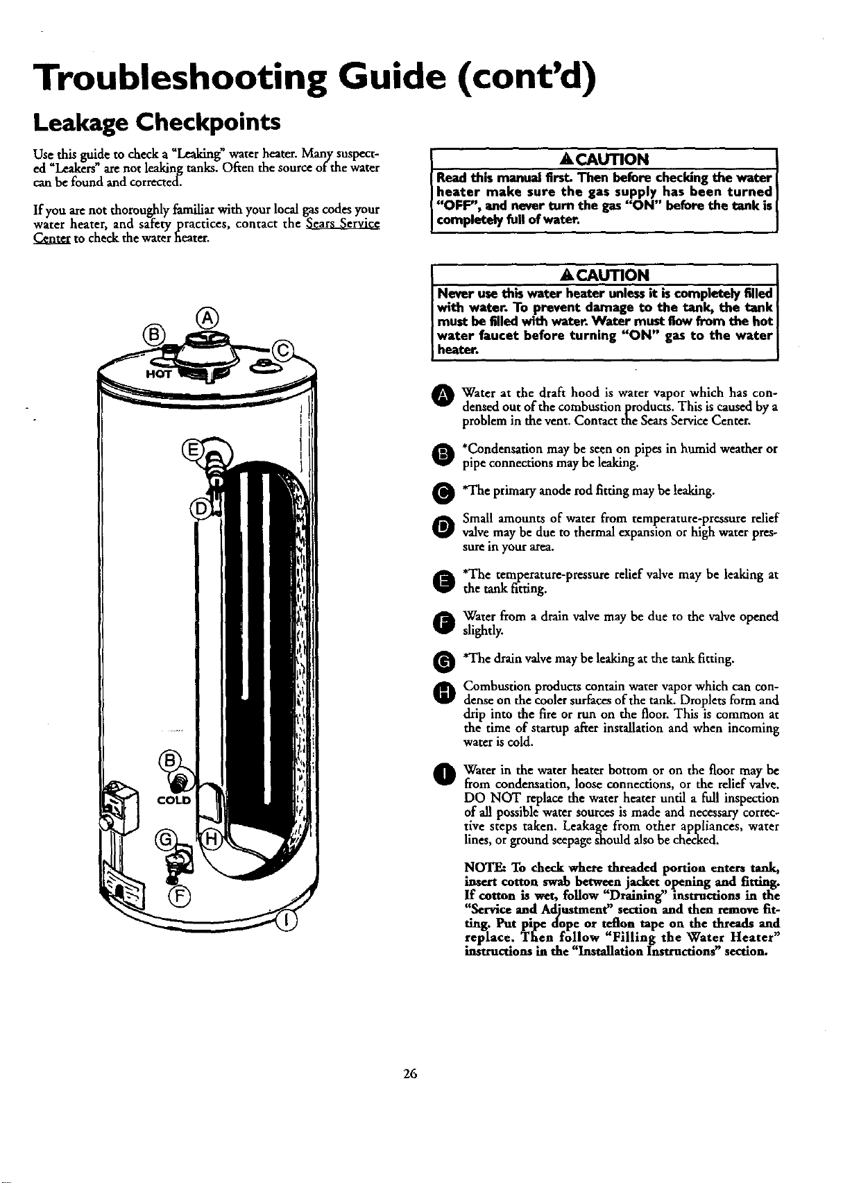
Troubleshooting Guide (cont'd)
Leakage Checkpoints
Use this guide to check a _Leaking_water heater. Many suspect-
ed _Leakers"are not leaking tanks. Often the source of the water
can be found andcorrected.
If you arenot thoroughly familiar with your local gas codes your
water heater, and safety practices, contact the
Center to check the water heater.
• ACAUTION I
Read this manual Erst. Then before checking the water
heater make sure the gas supply has been turned]
"OFF", end never turn the gas"ON" before the tank is
comp etely fullof water,
® ®
A CAUTION [
Never usethk water heater unlessit iscompletely filled ]
with water. To prevent damage to the tank, the tank
must be filled with water. Water must flow from the hot I
water faucet before turning "ON" gas to the water I
heater.
Water at the draft hood is water which has con-
vapor
densed out of the combustionprodncts. This is caused by a
problem in the vent. Contact the Sears Service Center.
O *Condensation may be seen on pipes in humid weather or
pipe connections may be leaking.
O'The primary anode rod fitting be leaking.
may
O Small amounts of water from temperature-pressure relief
valve may be due to thermal expansion or high water pres-
sure in your area,
o'The temperature-pressure relief valve may be leaking at
the tank fitting.
O Warer from a drain valve may be due to the valve opened
slightly.
O'The drainvalvemay be leaking at the tank fitting.
O Combustion products contain water vapor which can con-
dense on the cooler suff_ees of the tank. Droplets form and
drip into the fire or run on the floor. This is common at
the time of startup after installation and when incoming
water is cold.
Water in the water heater bottom or on the floor may be
from condensation, loose connections, or the relief valve.
DO NOT replace the water heater until a full inspection
of all possible water sources is made and necessary correc-
tive steps taken. Leakage from other appliances, water
lines, orground seepageshould also be checked.
NOTE: To check where threaded portion enters tank,
insert cotton swab between jacket opening and fitting.
If cotton is wet, follow "Draining" instructions in the
"Service and Adjustment" section and then remove fit-
ting. Put pipe dope or teflon tape on the threads and
replace. Then follow "Filling the Water Heater"
instructions in the "Installation Insttuctlon_' section.
26

Notes
27
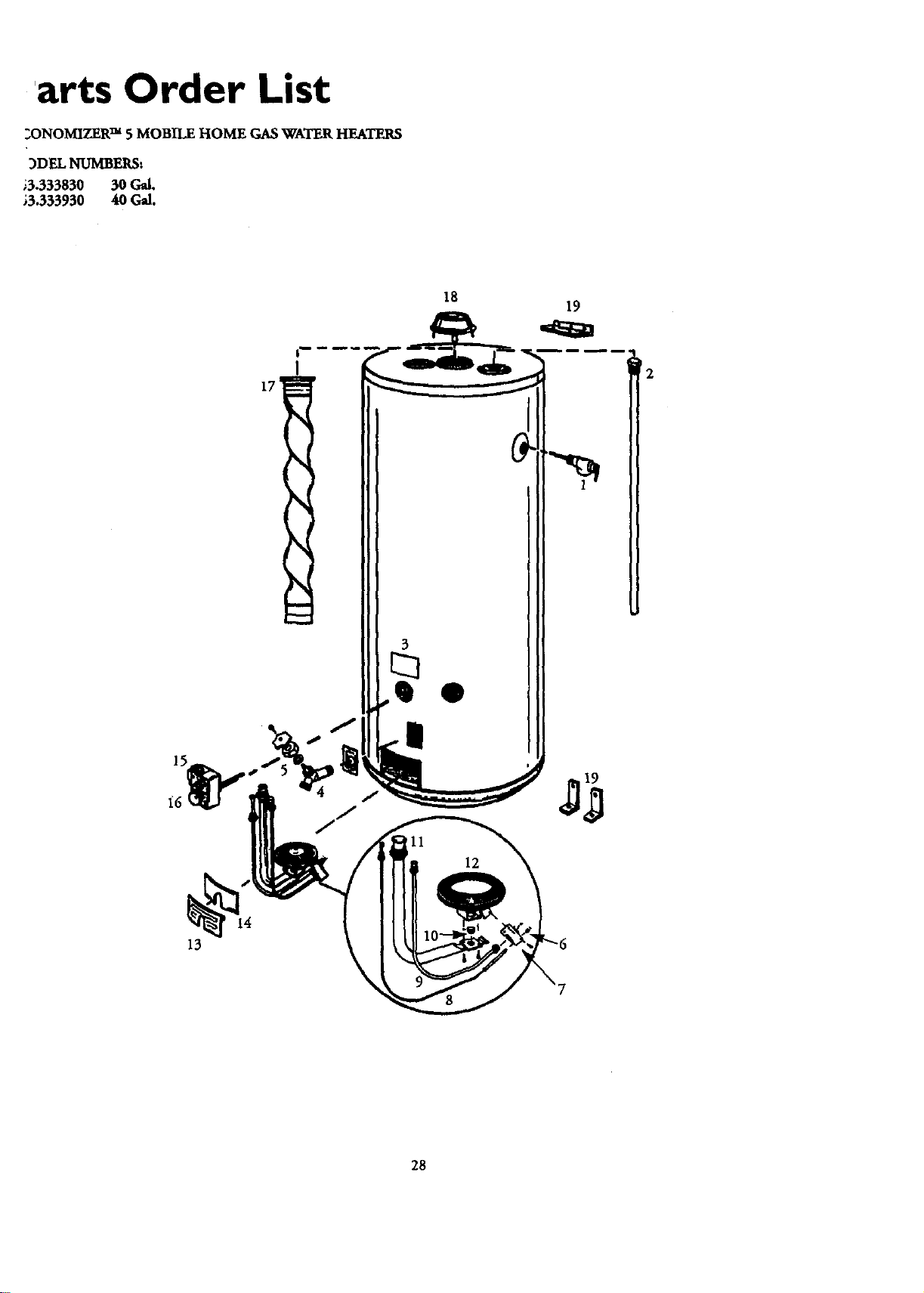
'arts Order List
2ONOMIZER TM 5 MOBILE HOME GASWATER HEATERS
3DEL NUMBERS:
•3.333830 30 Gal.
,3.333930 40 Gal.
ZT_
18
19
_2
13
28
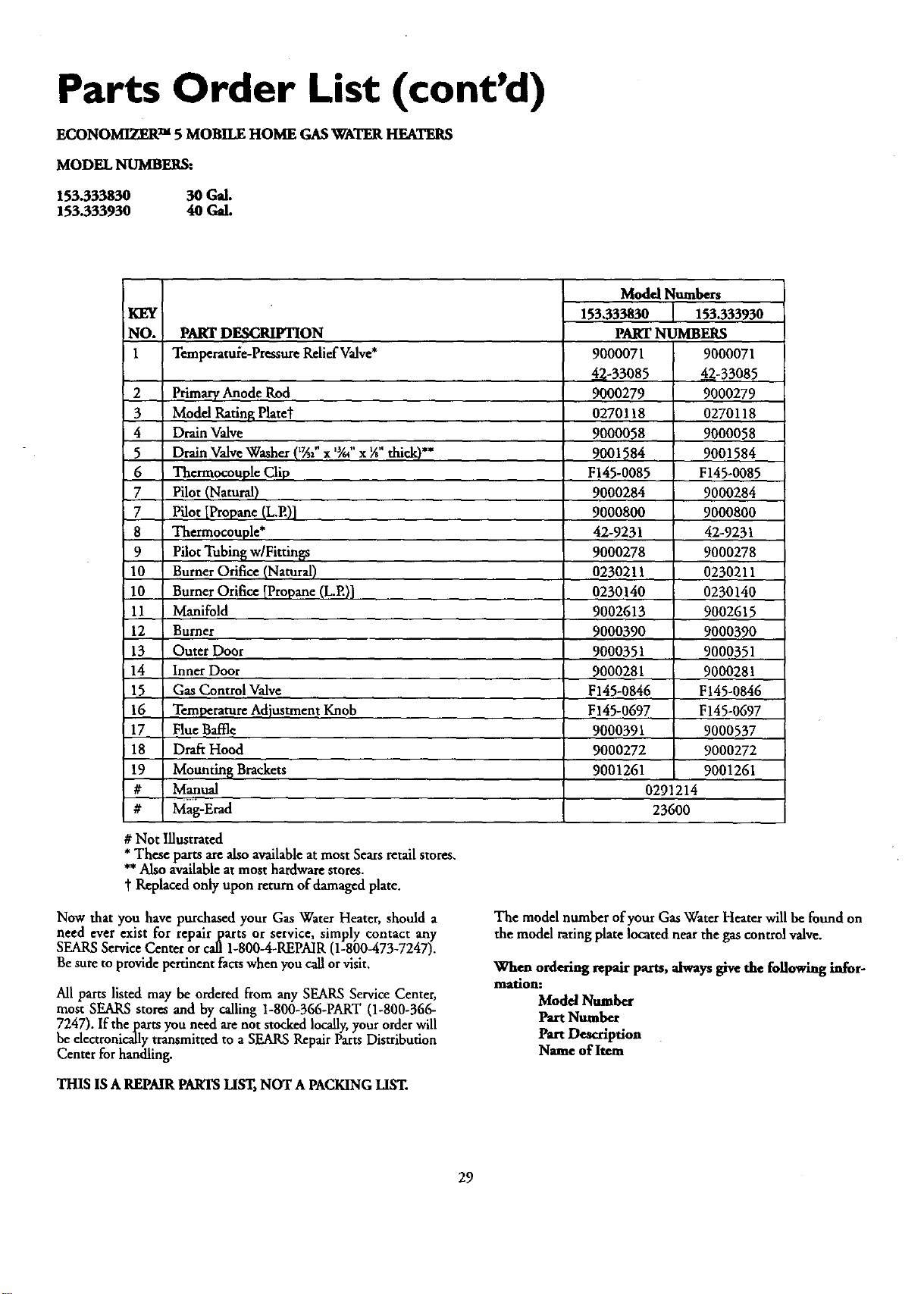
Parts Order List (cont'd)
ECONOMIZER TM 5 MOBILE HOME GASWATER HEATERS
MODEL NUMBERS:
153.333830 30 Gal.
153.333930 40 Gal.
KEY _
NO.
1
PART DESCRIFI_ON
Temperstule-PrrssureRalief Valve*
2 Primary Anode Rod
3 Modd Rating Platet
4 Drain Valve
5 Drain Valve Washer (_7A2"x 'gu"x ¼"thick)**
6 Tharmocouple Clip
7 Pilot (Natural)
7 Pilot [Propane (L.E)]
8 Thermocouple*
9 Pilot Tubing w/FittinBs
10 Burner Orifice (Natural)
10 Burner Orifice [Propane (L.E)]
11 Manifold
12 Burner
13 Outer Door
14 Inner Door
15 Gas Control Valve
16 TemperatureAdjustment Knob
17 Flue Baffle
18 Draft Hood
19 Mounting Brackets
# Manual
# Mag-Erad
Modal Numbers
153,333830 153.333930
PART NUMBERS
9000071 9000071
42-33085 4=_-33085
9000279 9000279
0270118 0270118
9000058 9000058
9001584 9001584
F145-0085 F145-0085
9000284 9000284
9000800 9000800
42-9231 42-9231
9000278 9000278
0230211 0230211
0230140 0230140
9002613 9002615
9000390 9000390
9000351 9000351
9000281 9000281
F145-0846 F145-0846
F145-0697 F145-0697
9000391 9000537
9000272 9000272
9001261 9001261
0291214
23600
# Not Illustrated
*These parts are also availableat most Sears retail stores.
**Also availableat most hardware stores.
t Replaced only upon return of damaged plate.
Now that you have purchased your Gas Water Heater, should a
need ever exist for repair parts or service, simply contact any
SEARSService Center or call 1-800-4-REPAIR (1-800-473-7247).
Be sure to provide pertinent factswhen you call orvisit,
All parts listed may be ordered from any SEARS Service Center,
most SEARS stores and by calling 1-800-366-PART (1-800-366-
7247). If the pasts you need axenot stocked locally,your orderwill
be electronically transmitted to a SEARS RepairParts Distribution
Center for handling.
THIS ISA REPMR PARTSLIST,NOT A PACKING LIST.
The model number of your Gas Water Heaterwill befound on
the model rating plate located near the gas controlvalve.
When ordering repair parts, always give the following infor-
marion:
Model Number
Part Number
Part Description
Name of Item
29

_lotes
30

Notes
31
Warranty
About Your Warranty
THE PRICE OF YOUR WATERHEATERDOES NOT INCLUDE
A FREE CHECKUP SERVICECALL.On Water Heater Instalatlom
ArrangedBySears,Searswarrantsthe installation.
ON INSTALLATIONSNOT MADE BY SEARSAUTHORIZED
CONTRACTORS:
1.YourSearswarrantyappliesto the product only,
2, Searsdoesnot warrant the installation.
3. A charge will be madeon servicecallsdue to poor or incomplete
imtalladon. Theseindude:
a.Adjustingthermostat.
b. Lightingpilot.
c. Leaksin pipesorfittings.
d. Improperventing
e. Condensation
This manual is in non-technicalhngusge. It may help you,avoidthe
cost of a needless servicecall. Many servicecallsreallyarentneeded.
Suchaswhen:
1.The gasis turned "OFF".
2.The pilot isout.
3.A gasorwaterleakisdueto loosepipe orconnections.
FULL ONE YEAR WARRANTY ON WATER HEATER
For one year from the date of purchase, when your Sears Kealmom water heater is installed and operated in accordancewith
the instructions in this manual Searswill:
1. Repairdefects in material orworkmanship in this water heater, free of charge.
2. Furnish and install a new current model water heater of equal capacity and quality, free of charge, ifa leak occurs in the
tank.
LIMITED WARRANTY ON TANKS THAT LEAK
After one year and through 5 years from the date of purchase, if a leak occurs in the tank, Sears will furnish a new current
model water heater of equal capacity and quality. You will be charged for installation.
If the water heater is subjected to commercial, institutional, industrial or other non-residential use, the above warranty cover-
age for tanks that leak is effective for 2 years from the date of purchase.
i
To obtain warranty service, SIMPLY CONTACT THE NEAREST SEARS STORE OR SEARS SERVICE CENTER IN
THE UNITED STATES This warranty applies onlywhile this product ]sin use in the United States.
This warranty gives you specific legal rights and you may also have other rights which vary from state to state.
"SEARS, ROEBUCK AND CO., Dept. 817 WA, Hoffman Estates, IL 60179"
Sears Installation Warranty
In addition to any warranty.¢xrendedto you on the Searsmerchandise
involved,which warranty becomeseffectivethe datethe merchandiseis
installed should the workmanship of any Searsarran_d installation
prove faulty within oneyear, Searswill, upon notice from you, cause
such faultsto be correctedat no additionalcostto you. If youwant this
heater professionallyinstalledby Searscontact your SearsSalesperson.
Theywill arrangeforprompt, qualityinstallation.
Parts Ordering Information
The modelnumber ofyour gaswaterheater isfound on the modelrat-
ingplateonthe front of the waterheater.
Sears Installation Policy
Allinstallationlaborarrangedby Searsshallbeperformed inaneat,
workmanlikemanner in accordancewithgenerallyacceptedtrade prac-
tices.Further,alliustallatiomshallcomplywith alllocalfaws,codes
regulationsand ordinances.The customershallalsobeprotected,dur-
inginstallation,byinsurancerelatingto propertydamage,Worker's
Compensation and PublicLiability.
Ifyou wantthis waterheater professionallyinstalledbySearscontact
yourSalesperson.Theywillarrangeforprompt, quality installationby
Searsauthorizedcontractors.
Fortherepairorreplacementpartsyouneed
delivereddirectlytoyourhome
Call7am-7 pro,7daysaweek
1-800-366-PART
(1-eoc_6e-727e)
Forin-homemajorbrandrepairservice
Call24hoursaday,7 daysaweek
1-800-4-REPAIR
(1-800-473-7247)
Sears, Roebuck and Co., Hoffman Estates, IL 60 179 U.S.A. 029_z_4-_.