Owners
Manual
FORPOTABLEWATER
HEATINGONLY
NOT SUITABLEFOR
SPACEHEATING
NOT FOR USE IN
MOBILE HOMES
Model No.
153.33231830 Gal.HighAltitude
153.33236230 Gal.
153.33241840 Gal.HighAltitude
153.33246240 Gal.
153.332562SOGal.
Caution:
Read and Follow
All Safety Rules and
Operating Instructions
Before First Use of
This Product.
Savethis Manual for Future Reference.
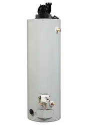
THE ECONOMIZER TM 6
GAS WATER HEATER
• Safety Instructions • Care and Maintenance
• Installation • Troubleshooting
• Operation • Parts List
For Your Safety
AN ODORANT IS ADDED TO THE GAS USED BY THIS
WATER HEATER
WARNING: If the information in these instructions are not fol-
lowed exactly, a fire or explosion may result, causing property
damage, personal injury or death.
-Do not store or use gasoline or other flammable vapors and liq-
uids in the vicinity of this or any other appliance.
-WHAT TO DO IF YOU SMELL GAS
Do not try to light any appliance.
Do not touch any electr,'cal switch; do not use any phone in your
building. . .
• Immediately call your gas supplier from a neighbor's phone.
Follow the gas supplier's|nstruct0-'ons.
• If you can not reach your gas supplier, call the fire department.
-Installation and service must be performed by a qualified installer,
service agency or the gas supplier.
•,WARNING . I
Improper installation, adjus_on, servfce or maintenance l
can cause DEATH, SERIOUS BODILY INJURY, OR PROPERTY DAM-I
AGE. Refer to this manual for assistance or consult the local Sears
Service Center or gas utility for further information.
AWARNING
Flammable vapors may be drawn by air currents from other areas
of the structure to this appliance.
_WARNING
READ THE GENERAL SAFETY SECTION BEGINNING ON INSIDE
COVER AND THEN THIS ENTIRE MANUAL BEFORE INSTALLING
OR OPERATING THIS WATER HEATER.
Sears, Roebuck and Co., Hoffman Estates, IL 60179 U.S.A.
Safety Precautions
I _,WARNING
Improper instailatio_lteratlon, service or
maintenance can cause DEATH, SERIOUS BODILY
INJURY, OR PROPERTY DAMAGE. Refer to this manu-
al for assistance or consult your local Sears Service
Center for further information.
_WARNING
WATER HEATERS EQUIPPED FOR ONE TYPE GAS
ONLY: This water heater is equipped for one type gas
only. Check the model rating plate near the gas control
valve for the correct gas. DO NOT USE THIS WATER
HEATER WITH ANY GAS OTHER THAN THE ONE
SHOWN ON THE MODEL RATING PLATE. Failure to
usethe correct gascan cause problems which can result in
DEATH, SERIOUS BODILY INJURY, OR PROPERTY
DAMAGE. If you have any questions or doubts consult
your gassupplier or localutility.
_,WARNING
INSTALLATIONS IN AREAS WHERE FLAMMABLE LIQ-
UIDS (VAPORS) ARE LIKELY TO BE PRESENT OR
I STORED (GARAGES, STORAGE, AND UTILITY AREAS,
ETC): Flammable liquids (such as gasoline, solvents,
I propane (LP) or butane, etc.), all ofwhich emit flammable
vapors, may be improperly stored or used in such areas.
The gaswater heater pilot light or main burner can ignite
such vapors. The resulting flashback and fire can cause
death or serious burns to anyone in the area, as well as
property damage.
If installation in such areas is your only option, then the
installation must be accomplished in a way that the pilot
flame and main burner flame are elevated from the floor
at least 18 inches.While this may reduce the chancesof
flammable vapors from a floor spill being ignited, gasoline
and other flammable substancesshouldnever be stored or
used in the same room or area containing a gas water
heater or other open flame or spark producing appliance.
NOTE: Flammable vapors may be drawn by air currents
from other areas of the structure to the appliance.
&WARNING
If this water heater will be used in beauty shops,barber
shops, cleaning astablishments, or self-service laundries
with dry cleaning equipment, it is imperative that the
water heater or water heaters be installed so that com-
bustion and ventilation air be taken from outside these
areas. Refer to the "Facts to Consider About the
Location" section of this manual and also the latest edi-
tion of the National Fuel Gas Code, ANSI Z223.1, also
referred to as NFPA 54 for specifics provided concerning
air required.
AWARNING I
A fire canstart if combustiblematerialssuchasclothing,
cleaningmaterials,or flammableliquidsare placedagainstI
or nexttothewaterheater. - I
A, WARNING
At the time of manufacture this water heater was provid-
led with a combination temperature-pressures relief valve
certified by a nationally recognized testing laboratory
that maintains periodic inspection of production of listed
equipment or materials, as meeting the requirements
for Relief Valves and Automatic Gas Shutoff Devices for
Hot Water Supply Systems, and the latest edition of
ANSI Z21.22 and the code requirements of ASME. If
replaced, the valve must meet the requirements of local
codes, but not lessthan a combination temperature and
pressure relief valve certified as meeting the require-
ments for Relief Valves and Automatic Gas Shutoff
Devices for Hot Water Supply Systems, ANSI Z21.22 by
a nationally recognized testing laboratory that maintains
periodic inspection of production of listed equipment or
materials.
The valve must be marked with a maximum set pressure
not to exceed the marked hydrostatic working pressure
of the water heater (150 Ibs./sq. in.) and a discharge
capacity not less than the water heater input rate as
shown on the model rating plate. (Electric beaters -
watts divided by 1000x 3415 equal BTUIHr. rate.)
Your local jurisdictional authority, while mandating the
use of a temperatur_-pr .,ssqre relie_ v; Ive Fomplying
with ANSI Z21.22 an_AS _lE,imay requi_ =a v_aivemodel
different from the onetfun _ish_dwith the _rate(r heater.
Compliance with sucl_Iocd r_quirem_nU, mr(st be satis-
fied by the installer o4 en_ user of thej wa :er I_eater with
a locally prescribed _em )er_,ture-pr_ssl re Relief valve
installed in the design_tecJope_nin_in,he vatqrheater in
place ofthe factory fujnlsl ,ed_aiv_. |
i
For safe operation ofithe water heather, :he _elief valve
must not be remove_ fr ,m _t's_esi_nal ed _pening or
plugged. | _ 1 ! !
The temperature-pre_sur _re(ief _e m ,st I_e installed
directly into the fitting e Fth_ wa_tar_hezter_designated
for the relief valve. Po_itidn th_ val_ dow _wa_dand pro-
vide tubing so that arty d_charge d_l{ exi_odJywithin 6
inches above, or at any di=ftance below the _tructural
floor. Be certain that _fo €0ntact_is ffiEde._with any live
electrical part. The discharge opening must n'bt be
blocked or reduced in size under any circumstances.
Excessivelength, over 30 feet, or use of more than four
elbows can:cause restriction and reduce the discharge
capacity of the valve.
No valve or other obstruction is to be placed between
the relief valve and the tank. Do not connect tubing
directly to discharge drain unlessa 6" air gap isprovided.
To prevent bodily injury, hazard to life, or property dam-
age, the relief valve must be allowed to discharge water
in quantities should circumstances demand. If the dis-
charge pipe is not connected to a drain or other suitable
means, the water flow may causeproperty damage.
The Discharge Pipe:
• Must not be smaller in size than the outlet pipe size of
the valve, or have any reducing couplings or other
restrictions.
• Must not be plugged or blocked.
• Must be of material listed for hot water distribution.
• Must be installed so as to allow complete drainage of
both the temperature-pressure relief valve, and the
dischargepipe.
• Must ternljnate at an adequate drain.
• Must not have any valve between the relief valve and
tank.
2
Safety Precautions
_,WARNING
A gas water heater cannot operate properly without the
correct amount of air for combustion. Do not install in a
confined area such a closet, unless you provide air as
shown in the "Facts to Consider About the Location" sec-
tion. Never obstruct the How of ventilation air. If you have
any doubts or questions at all, call your gas company.
Failure to provide the proper amount of combustion air
can result in a fire or explosion and can cause DEATH
SERIOUS BODILY INJURY,OR PROPERTY DAMAGE.
_,WARNING
This water heater must not be installed directly on car-
peting. Carpeting must be protected by a metal or wood
panel beneath the appliance extending beyond the full
width and depth of the appliance by at least 3 inches
(76.2mm) in any direction, or if the appliance is installed
Iin an alcove or closet, the entire floor must be covered by
;the panel. Fa ure to heed th s warn ng may result n a
fire hazard.
A,WARNING
HOTTER WATER CAN SCALD: Water heaters are
intended to produce hot water. Water heated to a tem-
pereture which will satisfy clothes washing, dish washing,
and other sanitizing needs can scald and permanently
injure you upon contact. Some people are more likely to
be permanently injured by hot water than others. These
include the elderly, children, the infirm, or physically/men-
tally handicapped. If anyone usinghot water in your home
fits into one of these groups or if there is a local code or
state law requiring a certain temperature water at the hot
water tap, then you must take special precautions. In addi-
tion to usingthe lowest possible temperature setting that
satires your hot water needs, a means such as a mixing
valve, should be used at the hot water taps used by these
people or at the water heater. Mixing valves are available
at plumbing supply or hardware stores. Follow manufac-
turers instructions for installation of the valves. Before
changing the factory setting on the thermostat, read the
"Temperature Regulation" section in this manual.
A,WARNING
Soot build-up indicates a problem that requires correc-
tion before further use. Turn "OFF" gas to water heater
and leave "OFF" until repairs are made, because failure
to correct the causeof the sooting can result in a Ere or
explosion causing DEATH, SERIOUS BODILY INJURY,
OR PROPERTY DAMAGE.
&WARNING
VENT DAMPERS - Any vent damper, whether it isoperat-
ed thermally or otherwise must be removed if its use
inhibitsproper drafting ofthe water heater.
Thermally Operated Vent Dampers: Gas-fired water
heaters having thermal efficiency in excess of 80% may
produce a relatively low flue gas temperature. Suchtem-
paratures may not be high enough to properly open ther-
mall), operated vent dampers. This would causespillageof
flue gasesand may cause carbon monoxide poisoning.
Vent dampers must bear evidence of certification as com-
splying with the latest edition of American National
taodard ANSI Z21.68 (ANSI Z21.66 & 67, respectively,
cover electrically and mechanically actuated vent
dampers). Before installation of any vent damper, consult
your local Sears Service Center or the gas utility for fur-
ther information.
&WARNING
• The appliance and its individual shutoff valve must be dis-
connected from the gas supply piping system during any
pressure testing of the gas system at test pressures in
excessof ½ pound per square inch(3.SkPa).
• The appliance must be isolated from the gassupply pip-
ing system by closing its individual manual shutoff valve
during any pressure testing of the gas supply piping sys-
tem at test pressures equal or less than _/2pound per
square inch (3.SkPa).
_,WARNING
BEFORE LIGHTING [PROPANE (L.R) GAS WATER
HEATERS]: Propane (L.R) gas is heavier than air. Should
there be a leak in the system, the gas will settle near the
ground. Basements, crawl spaces, skirted areas under
mobile homes (even when ventilated), closets and areas
below ground level will serve as pockets for the accumula-
tion of this gas. Before attempting to light or relight the
water heater's pilot or turning on a nearby electrical light
switch, be absolutely sure there is no accumulated gas in
the area. Search for odor of gasby snimng at ground level
in the vicinity of the appliance. If odor is detected, follow
steps indicated at "For Your Safety" on the cover page of
this manual then leave the premises.
A, WARNING
Chemical vapor corrosion of the flue and vent system
may occur if air for combustion contains certain chemical
vapors. Spray can propellants, cleaning solvents,refrigera.
tor and air conditioner refrigerants, swimming pool
chemicals, calcium and sodium chloride, waxes, bleach,
and process chemicals are typical compounds which are
potentially corrosive.
&,WARNING
Obstructed or deteriorated vent systems may present a
serous heath r skor asphyxat on.
Safety Precautions continued on page 4.
3
Safety Precautions
a, WARNING
The water heater with draft hood installed must be prop-
erly vented to a chimney which terminates outdoors.
Never operate the water heater unless it isvented to the I
I outdoors and has adequate air supply to avoid risks of_
I improper operation, explosion or asphyxiation. I
&WARNING
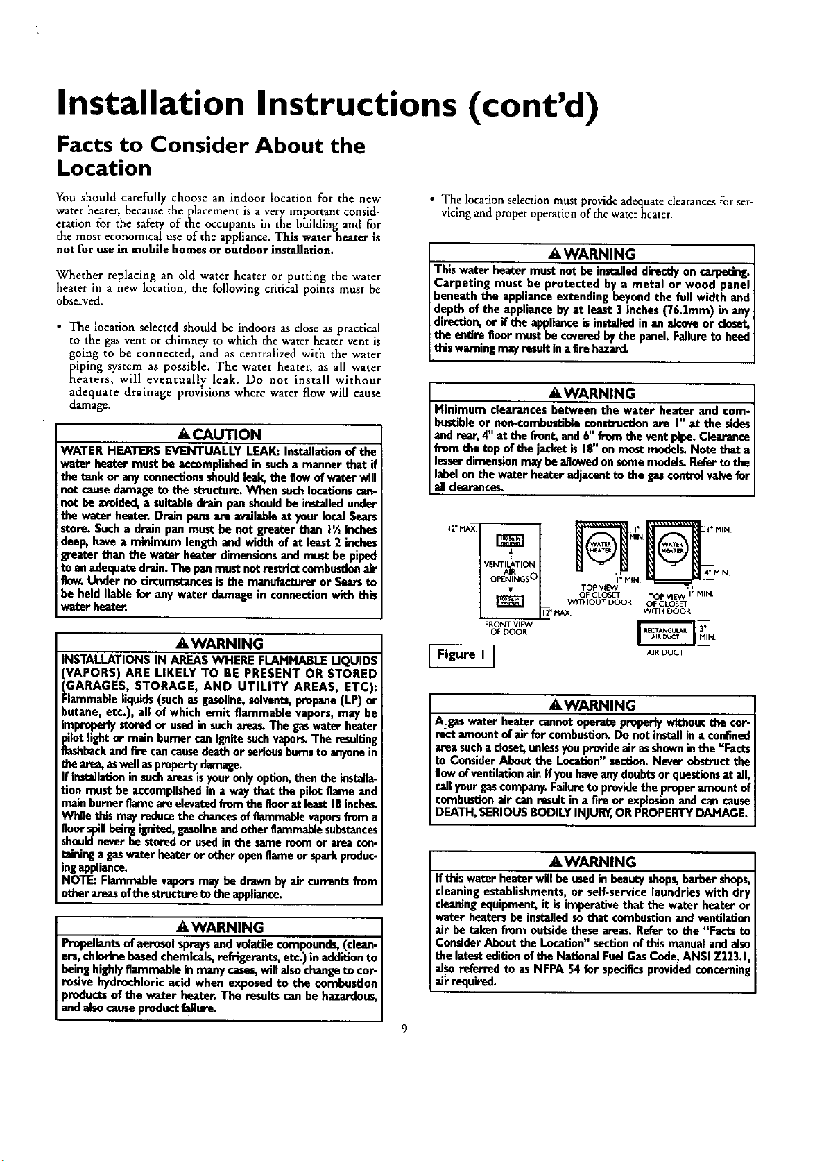
Minimum dearences between the water heater and com-
bustible or non-combustible construction are I" at the
sidesand rear, 4" at the front, and 6" from the vent pipe.
Clearance from the top of the jacket is 18" on most mod-
els. Note that a lesser dimension may be allowed on some
models. Refer to the label on the water heater adjacent to
the _as control valve for all clearances.
A CAUTION
WATER HEATERS EVENTUALLY LEAK: Installation of
the water heater must be accomplished in sucha manner
that if the tank or any connections should leak, the flow of
water will not causedamage to the structure. When such
locations cannot be avoided, a suitable drain pan should
be installed under the water heater. Drain pans are avail-
able at your local Sears store. Such a drain pan must be
not greater than I _ inches deep, have a minimum length
and width of at least 2 inches greater than the water
heater dimensions and must be piped to an adequate
!drain. The pan must not restrict combustion air flow.
IUnder no circumstances is the manufacturer or Sears to i
be held liable for any water damage in connection with
Ithis water heater.
&WARNING I
Do not use this appliance if any part of it has been under
water. Immediately call a Sears Service Technician to
inspect the appliance and to replace the gascontrol or any
_artof the burner system wh ch hasbeen under water.
_"WARNING
HYDROGEN GAS: Hydrogen gascan be produced in a hot
water system that has not been used for a long period of
time (generally two weeks or more). Hydrogen gas is
extremely flammable and explosive. To prevent the possi-
bility of injury under these conditions, we recommend the
hot water faucet be opened for several minutes at the
kitchen sink before any electrical appliances which are
connected to the hot water system are used(such asa dis-
hwasher or washing machine). If'hydrogen gas is present,
there will probably be an unusual sound similar to air
escaping through the pipe as the hot water faucet is
opened. There must be no smoking or open flame near
Ithe faucet at the time it isopen.
A, WARNING
INSULATING JACKETS: When installing an external
water heater insulation iacket on agaswater heater:
• DO NOT cover the temperature-pressure relief valve.
• DO NOT put insulation over any part of the top of the
gaswater heater,
• DO NOT put insulation over the gascontrol valve or gas
control valve/burner cover, or any access areas to the
burner.
• DO NOT let insulation around the gas water heater to
get within 8 inches of the floor (air must get to the
burner).
• DO NOT cover or remove operating instructions, and
safety related warning labelsand materials affixed to the
water heater.
Failure to heed this will result in the possibility of a fire or
explosion.
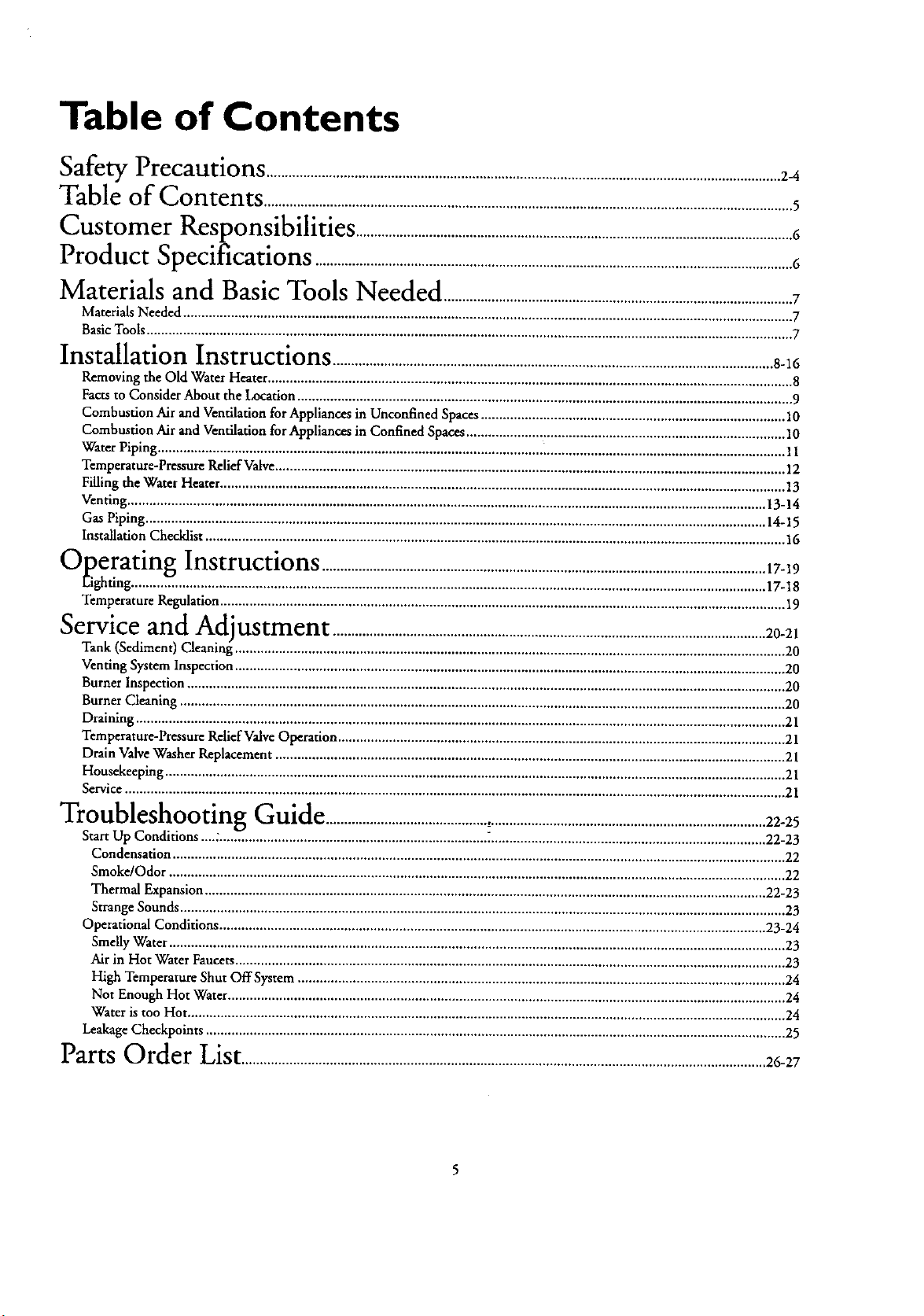
Table of Contents
q_"_'_,a.,.LjPrecautions .........................................................................................................................2-4
Table of Contents ................................................................................................................................................5
Customer
Kesponslt)llmes .......................................................................................................................6
Product
_pecmcauons ..................................................................................................................................6
Materials and Basic Tools Needed ...............................................................................................7
Materials Needed ...................................................................................................................................................................... 7
Basic Tools ................................................................................................................................................................................ 7
Installation Instructions ........................................................................................................................8-16
Removing the Old Water Heater ............................................................................................................................................... 8
Facts to Consider About the Location ....................................................................................................................................... 9
Combustion Air and Ventilation for Appliances in Unconfined Spaces ................................................................................... 10
Combustion Air and Ventilation for Appliances in Confined Spaces ....................................................................................... 10
Water Piping ......................................................................................................... _................................................................. 11
Temperature-Pressure Relief Valve........................................................................................................................................... 12
Filling the Water Heater .......................................................................................................................................................... 13
Venting .............................................................................................................................................................................. 13-14
Gas Piping ......................................................................................................................................................................... 14-15
Installation Checklist .............................................................................................................................................................. 16
_"uperatmg Instructions .........................................................................................................................17-19
Eighting ............................................................................................................................................................................. 17-18
Temperature Regulation .......................................................................................................................................................... 19
Service
and
Actlustment ......................................................................................................................20-21
Tank (Sediment) Cleaning" ...................................................................................................................................................... 20
Venting System Inspection ...................................................................................................................................................... 20
Burner Inspection ................................................................................................................................................................... 20
Burner Cleaning ..................................................................................................................................................................... 20
Draining ................................................................................................................................................................................. 21
Temperature-Pressure Relief Valve Operation .......................................................................................................................... 21
Drain Valve Washer Replacement ........................................................................................................................................... 21
Housekeeping ......................................................................................................................................................................... 21
Service .................................................................................................................................................................................... 21
_" "" -"lroubleslaooting Guide ........................................................................................................................22-25
Start Up Conditions ....::........................................................................ ............................................................................ 22-23
Condensation ....................................................................................................................................................................... 22
Smoke/Odor ........................................................................................................................................................................ 22
Thermal Expansion ......................................................................................................................................................... 22-23
Strange Sounds ..................................................................................................................................................................... 23
Operational Conditions ..................................................................................................................................................... 23-24
Smelly Water ........................................................................................................................................................................ 23
Air in Hot Water Faucets ...................................................................................................................................................... 23
High Temperature Shut OffSystem ..................................................................................................................................... 24
Not Enough Hot Water ........................................................................................................................................................ 24
Water is too Hot ................................................................................................................................................................... 24
Leakage Checkpoints .............................................................................................................................................................. 25
Parts Order List....................................................................................26-27
Customer Responsibilities
Thank You for purchasing a Sears water heater. °
Properly installed and maintained, it should give you years of
trouble free service. If you should decide that you want the new
water heater professionally installed by Sears call the local Sears
Service Center or any Sears store. They will arrange for prompt,
quality installation by Sears authorized contractors.
Abbreviations Found In This Instruction Manual
A.G.A. - American Gas Association
A.N.S.I. _ American National Standards Institute
AWARNING
This gas-fired water heater is design certified by the
American Gas Association Laboratories under American
National Standards for Gas Water Heaters. The installa-
tion must conform with this manual, Local Codesand with
I the latest edition of the National Fuel Gas Code, ANSI
7223.1.
This publication isavailable from your local government or
public library, gas company, or by writing NFPA,
Batterymarch Park, Quincy,MA 02269.
• Read the "Safety Precautions" section, pages 2 through 4 of
this manual first and then the entire manual carefully. If you
don't follow the safety rules, the water heater will not operate
properly. It could cause DEATH, SERIOUS BODILY
INJURY AND/OR PROPERTY DAMAGE.
This manual contains instructions for the installation, opera-
tion, and maintenance of the gas-fired water heater. It also
contains warnings through out the manual that you must read
and be aware of. All warnings and all instructions are essential
to the proper operation of the water heater and your safety.
Since we cannot put everything on the first few pages, READ
THE ENTIRE MANUAL BEFORE ATTEMPTING TO
INSTALL OR OPERATE THE WATER HEATER.
The installation must conform with the instructions in this
manual; gas company rules; and Local Codes, or in the
absence of Local Codes, with the latest edition of the National
Fuel (]as code, ANSI Z223.1, also referred to as NFPA 54.
This publication is available from your local government or
public library or gas company or by writing NFPA,
Batterymarch Park, Quincy, MA 02269.
If after reading this manual you have any questions or do not
understand any portion o1: the instructions, call the Sears
Service Center.
Carefully plan the place where you are going to put the water
heater. Correct combustion, vent action, and vent pipe instal-
lation ate very important in preventing death from possible
carbon monoxide poisoning and fires.
Examine the location to ensure the water heater complies with
the "Facts to Consider About the Location" section in this
manual.
For California installation this water heater must be braced,
anchored, or strapped to avoid falling or moving during an
earthquake. See instructions for correct installation proce-
dures. Instructions may be obtained from your local dealer,
wholesaler, public utilities or California Office of the State
Architect, 400 P Street. Sacramento, CA 95814.
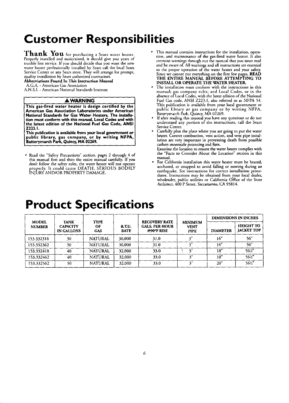
Product Specifications
MODEL
NUMBER
153.332318
153.332362
153.332418
153.332462
153.332562
TANK
CAPACITY
1NGALLONS
30
30
40
40
5O
TYPE
OF
GAS
NATURAL
NATURAL
NATURAL
NATURAL
NATURAL
B.T.U.
RATE
30,000
30,000
32,000
32,000
32,000
RECOVERY RATE
GAI_. PER HOUR
@90*FRISE
31.0
31.0
33.0
33.0
33,0
MINIMUM
VENT
PIPE
3,,
3"
! 3"
3"
3,,
DIMENSIONS IN INCHES
HEIGHT TO
DIAMETER JACKET TOP
t6" 56"
16" 56"
18" 56½"
18" 56½"
20" 5672"
6
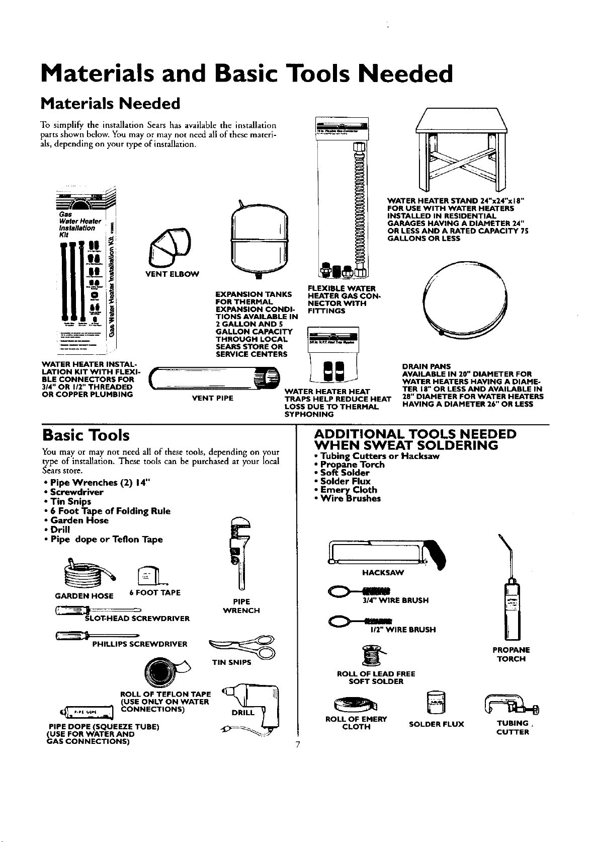
Materials and Basic Tools Needed
Materials Needed
To simplify the installation Sears has available the installation
parts shown below. You may or may not need all of these materi-
als, depending on your type of installation.
WATER HEATER INSTAL-
LATION KIT WITH FLEXI-
BLE CONNECTORS FOR
314" OR 112" THREADED
OR COPPER PLUMBING
EXPANSION TANKS
FOR THERMAL
EXPANSION CONDI-
TIONS AVAILABLE IN
2 GALLON AND 5
GALLON CAPACITY
THROUGH LOCAL
SEARS STORE OR
SERVICE CENTERS
FLEXIBLE WATER
HEATER GAS CON-
NECTOR WITH
FITTINGS
VENT PIPE
WATER HEATER HEAT
TRAPS HELP REDUCE HEAT
LOSS DUE TO THERMAL
SYPHONING
WATER HEATER STAND 24"x24"x18"
FOR USE WITH WATER HEATERS
INSTALLED IN RESIDENTIAL
GARAGES HAVING A DIAMETER 24"
OR LESS AND A RATED CAPACITY 75
GALLONS OR LESS
DRAIN PANS
AVAILABLE IN 20" DIAMETER FOR
WATER HEATERS HAVING A DIAME-
TER 18" OR LESS AND AVAILABLE IN
28" DIAMETER FOR WATER HEATERS
HAVING A DIAMETER 26" OR LESS
Basic Tools
You may or may not need all of these tools, depending on your
type of installation. These tools can be purchased at your local
Sears store.
• Pipe Wrenches (2) 14"
• Screwdriver
• Tin Snips
• 6 Foot Tape of Folding Rule
• Garden Hose
• Drill
• Pipe dope or Teflon Tape
GARDEN HOSE 6 FOOT TAPE
SLOT-HEAD SCREWDRIVER
PIPE
WRENCH
PHILLIPS SCREWDRIVER
ROLL OF TEFLON TAPE
(USE ONLY ON WATER
CONNECTIONS)
PIPE DOPE (SQUEEZE TUBE)
(USE FOR WATER AND
GAS CONNECTIONS)
TIN SNIPS
DRILL
ADDITIONAL TOOLS NEEDED
WHEN SWEAT SOLDERING
• Tubing Cutters or Hacksaw
• Propane Torch
• Soft Solder
• Solder Flux
• Emery Cloth
• Wire Brushes
HACKSAW
314" WIRE BRUSH
112"WIRE BRUSH
\
ROLL OF LEAD FREE
SOFT SOLDER
ROLL OF EMERY
CLOTH SOLDER FLUX TUBING
CUTTER
_;_ PROPANE
TORCH
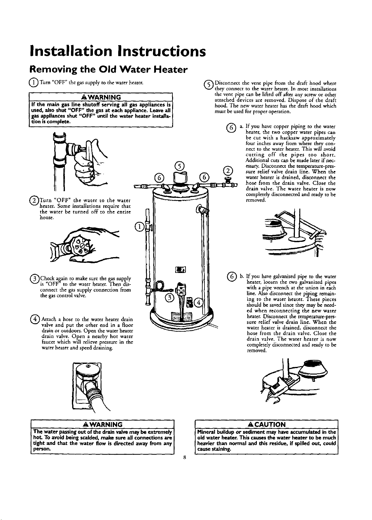
Installation Instructions
Removing the Old Water Heater
Turn "OFF" the gas supply to the water heater.
I AWARIqlNG
If the main gas line--all gas appliances is
used, also shut "OFF" the gas at each appliance. Leave all
gasappliances shut "OFF" until the water heater installa-
tion iscomplete. J
Turn "OFF" the water to the water
heater. Some installations require that
the water be turned off to the entire
house,
Check al_aln to sure gas supply
make the
is OFF to the water heater. Then dis-
connect the gas supply connection from
the gas control valve.
Attach hose the heater drain
a to water
valve and put the other end in a floor
drain or outdoors. Open the water heater
drain valve. Open a nearby hot water
faucet which will relieve pressure in the
water heater and speed draining.
Disconnect the vent pipe from the draft hood where
they connect to the water heater. In most installations
the vent pipe can be lifted off after any screw or other
attached devices are removed, Dispose of the draft
hood, The new water heater has the draft hood which
must be used for proper operation.
@@ @ @
a. If you have copper piping to the water
heater, the two copper water pipes can
be cut with a hacksaw approximately
four inches away from when: they con-
nect to the water heater. This will avoid
cutting off the pipes too short.
Additional cuts can be made later if nec-
essary. Disconnect the temperature-pres-
sure relief valve drain line. Whenthe
water heater is drained, disconnect the
hose from the drain valve. Close the
drain valve. The water heater is now
completely disconnected and ready to be
removed.
b.
If you have galvanized pipe to the water
heater, loosen the two galvanized pipes
with a pipe wrench at the union in each
line. Also disconnect the piping remain-
ing to the water heater. These pieces
should be saved since they may be need-
ed when reconnecting the new water
heater. Disconnect the temperature-pres-
sure relief valve drain line. When the
water heater is drained, disconnect the
hose from the drain valve. Close the
drain valve. The water heater is now
completely disconnected and ready to be
removed.
AWARNING I
The water passingout of the drain valve may be extremely I
hot. To avoid being scalded, make sure all connections are
tight and that the water flow is directed away from any
person.
ACAUTION ]
Mineral buildup or sediment may have accumulated in the|
old water heater. This causesthe water heater to be much|
heavier than normal and this residue, if spilled out, could|
causestoning. ]
Installation Instructions (cont'd)
Facts to Consider About the
Location
You should carefully choose an indoor location for the new
water heater, because the placement is a very important consid-
eration for the safety of the occupants in the building and for
the most economical use of the appliance. This water heater is
not for use in mobile homes or outdoor installation.
Whether replacing an old water heater or putting the water
heater in a new location, the following critical points must be
observed.
• The location selected should be indoors as close as practical
to the gas vent or chimney to which the water heater vent is
going to be connected, and as centralized with the water
[iping system as possible. The water heater, as all water
eaters, will eventually leak. Do not install without
adequate drainage provisions where water flow will cause
damage.
_, CAUTION
WATER HEATERS EVENTUALLY LEAK: Installation of the
water heater must be accomplishedin sucha manner that if
the tank or any connectionsshouldleak,the flowofwater will
not causedamageto the structure.When suchlocationscan-
not be avoided,a suitable drain pan shouldbe installedunder
the water heater, Drain pansare availableat your local Sears
store. Such a drain pan must be not greater than 1'/2inches
deep, have a minimum length and width of at least 2 inches
greater than the water heater dimensionsand must be piped
to an adequatedrain.The pan mustnotrestrictcombustionair
flow. Under on circumstancesisthe manufactureror Sears
be held liable for any water damage in connectionwith thi
water heater,
AWARNING
INSTALLATIONS IN AREASWHERE FLAMMABLE LIQUIDS
(VAPORS) ARE LIKELY TO BE PRESENT OR STORED
(GARAGES, STORAGE, AND UTILITY AREAS, ETC):
Flammableliquids(suchasgasoline,solvents,propane(LP) or
butane, etc.), all of which emit flammable vapors, may be
improperlystoredor usedin suchasea_ The gaswater heater
pilot lightor main bumer canignite suchvapor_ The resulting
flashbackand Ere cancausedeath or serious burnsto anyonem
the area,aswellaspropertydamage.
If installationin suchareasisyouronly option,then the installa.
tion must be accomplishedin a way that the pilot flame and
mainburnerflame are elevatedfromthe floorat least 18inches.
While this may reduce the chancesof8ammablevaporsfrom a
floor spillbeing ignited,gasolineandother flammable substances
shouldneverbe stored or usedin the same room or area con-
talnin8 a gaswater heateror other openflame or sparkproduc-
ingappliance.
NOTE: Flammablevaporsmay be drawnby air currentsfrom
otherareasof the structureto the appliance.
AWARNING
Propellantsof aerosol spraysand volatile compounds,(clean-
ers,chlorine basedchemicals,refrigerants,etc.) in addition to
beinghighlyflammable in many cases,will alsochangeto cor-
rosive hydrochloric acid when exposed to the combustion
productsof the water heater, The results can be hazardous,
and alsocauseproductfailure.
• The location selection must provide adequate clearances for ser-
vicing and proper operation of the waterheater.
_WARNING
This water heater must not be installeddirectlyon carpeting.
Carpeting must be protected by a metal or wood panel
beneath the appliance extending beyondthe full width and
depth of the appliance by at least 3 inches (76.2mm) in any
direction,or if the applianceisinstalledin an alcoveor closet,
the entire floormust be coveredby the panel,Failureto heed
thiswarningmayresultin afire hazard.
_,WARNING
Minimum clearances between the water heater and com-
bestible or non-combustibleconstructionare I" at the sides
and rear,4" at the front, and 6" from the vent pipe.Clearance
from the top of the jacketis 18"on most models.Note that a
lesserdimensionmay be allowed onsomemodels.Referto the
label onthe water heater adjacentto the gascontrolvalvefor
all clearances.
|VENTILATION I _I _w _ i_1 _
AIR i i 4" IMIN '
I _ I TOP V EVe ,,
OF CLOSET TOP Vl I" NIN.
L W_THOUT DOOR OF
L _, MAX WITH DOOR
FRONT VIE%V
OF DOOR
[ Figure I ] A,F_DUCT
AWARNING
A__gaswater heater cannot operate properlywithout the cor-
rect amount of air for combu_on. Do not installin a confined
areasucha deset, unlessyou provideair asshowninthe "Facts
to ConsiderAbout the Location"section. Never obstruct the
flowof ventilation air. Ifyou haveanydoubtsor questionsat all,
callyour gascompany.Failureto providethe proper amount of
combustionair can resultin a Ere or explosionand can cause
DEATH,SERIOUSBODILY INJUR_,OR PROPERTYDAMAGE.
AWARNING
If this water heater will be usedin beauty shops,barber shops,
cleaning establishments, or self.service laundries with dry
cleaningequipment, it isimperative that the water heater or
water heatersbe installed sothat combustionand ventilation
air be taken from outsidethese areas. Referto the "Facts to
ConsiderAbout the Location" sectionof this manual and also
the latestedition of the NationalFuelGasCode, ANSI Z223.1,
also referred to as NFPA 54 for specificsprovidedconcerning
aik required. I
Installation Instructions (cont'd)
Combustion Air and Ventilation
for Appliances Located in
Unconfined Spaces
Unconfined Space is a space whose volume is not less than 50
cubic feet per 1,000 Btu per hour of the aggregate input rating
of all appliances installed in that space, Rooms communicating
directly with the space in which the appliances are installed,
through openings not furnished with doors, are considered a
part of the unconfined space
In unconfined spaces in buildings, infiltration may be adequate
to provide air for combustion, ventilation and dilution of flue
gases. However, in buildings of tight construction (for example,
weather stripping, heavily insulated, caulked, vapor barrier, etc.),
additional air may need to be provided using the methods
described in Combustion Air and Ventilation for Appliances
Located in Confined Spaces, b.
Combustion Air and Ventilation
for Appliances Located in
Confined Spaces
Confined Space is a space whose volume is less than 50 cubic
feet per 1,000 Btu per hour of the aggregate input rating of all
appliances installed in that space.
a. ALL AIR FROM INSIDE BUILDINGS:
(See Page 9 Figure 1, and Figure 2 below)
The confined space shall be provided with two permanent
openings communicating directly with an additional room(s)
of sufficient volume so that the combined volume of all
spaces meets the criteria for an unconfined space. The total
input of all gas utilization equipment installed in the com-
bined space shall be considered in making this determination.
Each opening shall have a minimum free area of one square
inch per 1,000 BTU per hour of the total input rating of all
gas utilization equipment in the confined space, but not less
than 100 square inches. One opening shall commence within
12 inches of the top and one commencing within 12 inches
of the bottom of the enclosure.
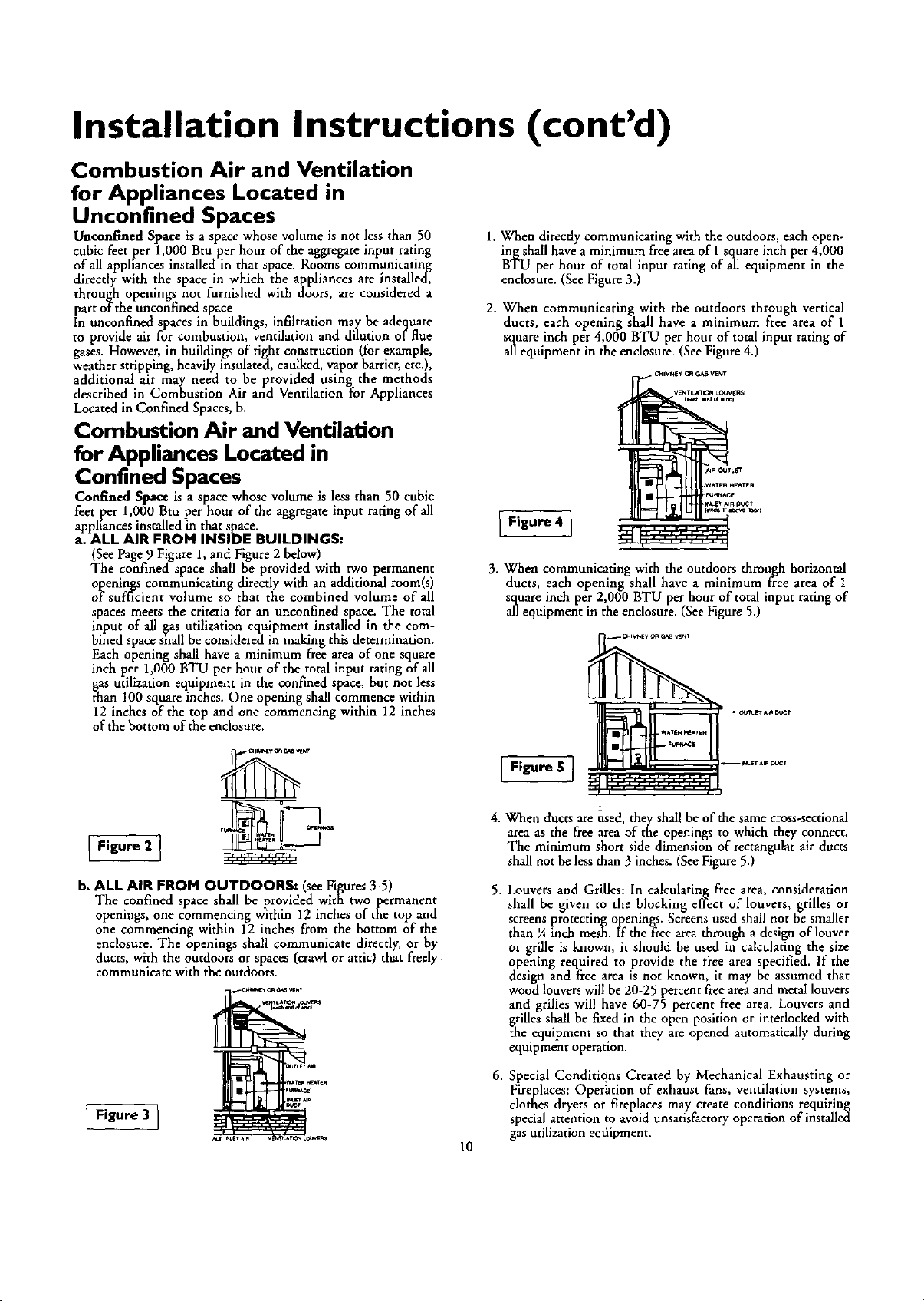
1. When directly communicating with the outdoors, each open-
ing shall have a minimum free area of I square inch per 4,000
BTU per hour of total input rating of all equipment in the
enclosure. (See Figure3.)
2. When communicating with the outdoors through vertical
ducts, each opening shall have a minimum free area of 1
square inch per 4,000 BTU per hour of total input rating of
all equipment in the enclosure. (See Figure 4.)
I Figure 4 I
3. When communicating with the outdoors through horizontal
ducts, each opening shall have a minimum free area of 1
square inch per 2,000 BTU per hour of total inputrating of
allequipment in the enclosure. (SeeFigure5.)
Figure 2 ]
ve_cr
b. ALL AIR FROM OUTDOORS: (seeFigures3-5)
The confined space shall be provided with two permanent
openings, one commencing within I2 inches of the top and
one commencing within 12 inches from the bottom of the
enclosure. The openings shall communicate directly, or by
ducts,with the outdoorsorspaces (crawl orattic) that freely.
communicate with the outdoors.
Figure 3 ]
10
Figure 5 ]
4. When ducts are _ed, they shall be of the same cross-sectional
area as the free area of the openings to which they connect.
The minimum short side dimension of rectangular air ducts
shall not be less than 3 inches. (See Figure 5.)
5. Louvers and Grilles: In calculating free area, consideration
shall be given to the blocking effect of louvers, grilles or
screens protecting openings. Screens used shall not be smaller
than ¼ inch mesh. If the free area through a design of louver
or grille is known, it should be used in calculating the size
opening required to provide the free area specified. If the
design and free area is not known, it may be assumed that
wood louvers will be 20-25 percent free areaand metal louvers
and grilles will have 60-75 percent free area. Louvers and
grilles shall be fixed in the open position or interlocked with
the equipment so that they are opened automatically during
equipment operation.
6. Special Conditions Created by Mechanical Exhausting or
Fireplaces: Opefiition of exhaust fans, ventilation systems,
clothes dryers or fireplaces may create conditions requiring
special attention to avoid unsatisfactory operation of installed
gas utilization eqfiipment.
Installation Instructions (cont'd)
Water Piping
AWARNING
HOTTER WATER CAN SCALD: Water heatersare intendedto
producehot water.Water heated to a temperature whichwill
satisfyclotheswashing,dishwashing,and other sanitizingneeds
canscaldand permanently injureyou uponcontact.Some peo-
_eare morelikelyto bepermanently injuredbyhot water than
others.Theseincludethe elderly,children,the infirm,or physicS-
b/mentally handicapped.If anyoneusinghot water inyour home
fitsintooneofthesegroupsor ifthere isa localcodeor statelaw
requiring acertaintemperature water at the hotwaterta_ then
_u musttakespeciaJprecaution_In additionto usingthe lowest
)ossibletemperature settingthat sadsflesyourhot water needs,
Lmeanssuchasa mixing valve,shouldbe usedat the hot water
tapsusedby these peopleor at the water heater.Mixingv'alves
are availableat plumbingsupplyor hardwarestore_ Followman-
ufacturers instructionsfor installation of the valves. Before
changing the factory setting on the thermostat, read the
'q'emperatureRegulation"sectioninthismanual.
a, WARNING ]
This water heater shall not be connected to anyl
heating systems or component(s) used with a non-
potab e water heat ng app ance.
AWARNING ]
Toxicchemicalssu_reatment of boilers
or non-potable water heating appliances shall never
be introduced nto a potab e water heat ng system.
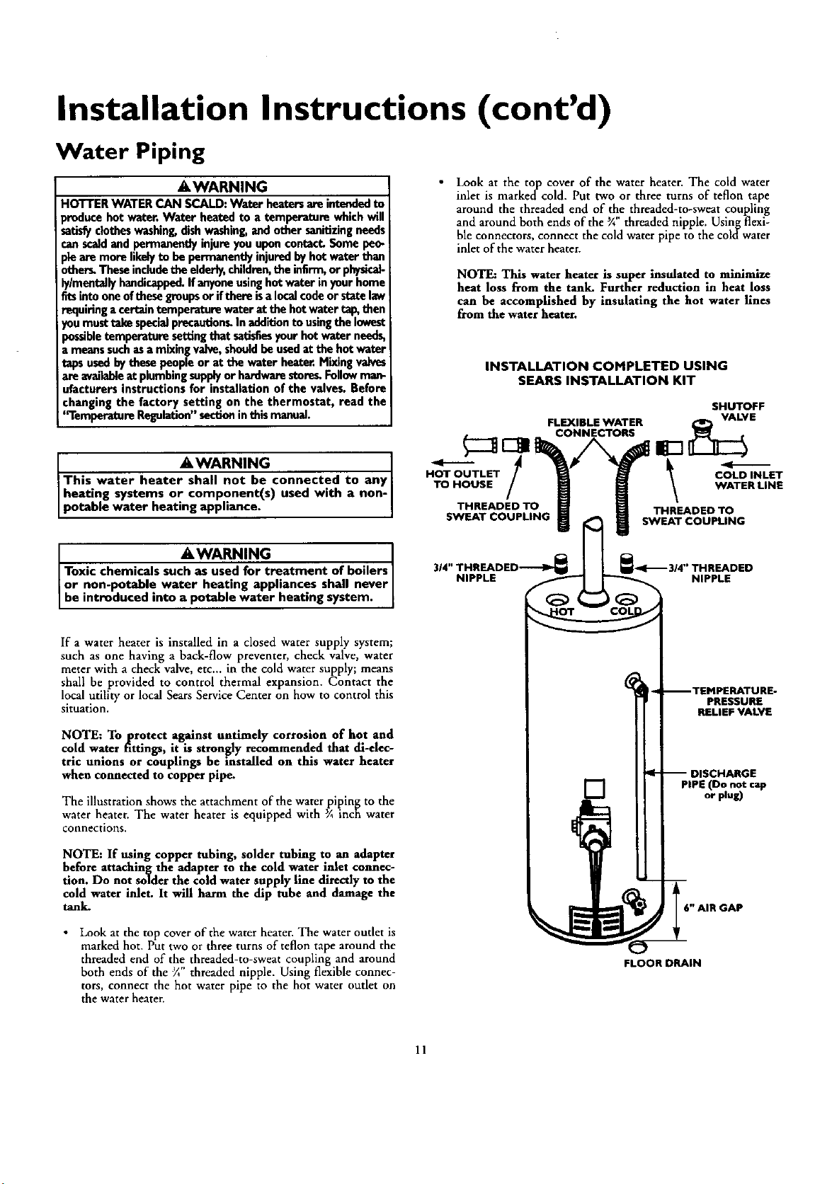
Look at the top cover of the water heater. The cold water
inlet is markedcold. Put two or three turns of teflon tape
around the threaded end of the threaded-to-sweat coupling
and around both ends of the ¾"threaded nipple. Usingflexi-
ble connectors, connect the coldwater pipe to the coldwater
inlet of the water heater.
NOTE: This water heater is super insulated to minimize
heat loss from the tank. Further reduction in heat loss
can be accomplished by insulating the hot water lines
from the water heater.
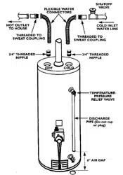
INSTALLATION COMPLETED USING
SEARS INSTALLATION KIT
-/
HOT OUTLET
TO HOUSE
THREADED TO
SWEAT COUPLING
FLEXIBLE WATER
CONNECTORS
SHUTOFF
VALVE
COLD INLET
WATER LINE
THREADED TO
SWEAT COUPLING
314"THREADED-_
NIPPLE
_1_ 314" THREADED
NIPPLE
If a water heater is installed in a closed water supply system;
such as one having a back-flow preventer, check valve, water
meter with a check valve, etc.., in the cold water supply; means
shall be provided to control thermal expansion. Contact the
local utility or local Sears Service Center on how to control this
situation.
NOTE: To protect against untimely corrosion of hot and
cold water fittings, it isstrongly recommended that all-elec-
tric unions or couplings be installed on this water heater
when connected to copper pipe.
The illustration shows the attachment of the water piping to the
water heater. The water heater is equipped with ¾ inch water
connections.
NOTE: If using copper tubing, solder tubing to an adapter
before attaching the adapter to the cold water inlet connec-
tion. Do not solder the cold water supply line directly to the
cold water inlet. It will harm the dip tube and damage the
tank.
• Look at the top cover of the water heater. The water outlet is
marked hot. Put two or three turns of teflon tape around the
threaded end of the threaded-to-sweat coupling and around
both ends of the ¾' threaded nipple. Using flexibleconnec-
tors, connect the hot water pipe to the hot water outlet on
the water heater.
[]
PRESSURE
RELIEF VALVE
PIPE (Do not cap
or plug)
6" AIR GAP
FLOOR DRAIN
11
Installation Instructions (cont'd)
Temperature.Pressure Relief Valve
&WARNING
At the time of manufacture this water heater was providedi
with a combinationtemperature-pressuresrelief valvecertlf_ed
by a nationally recognized testing laboratory that maintains
periodic inspectionofproduction of listedequipment or mate-
rials, as meeting the requirements for Relief Valves and
Automatic GasShutoffDevicesfor Hot Water SupplySystems,
and the latest edition of ANSI Z21.22 and the code require.
ments of ASME, If replaced, the valvemust meet the require-
mentsoflocalcodes,but not lessthana combinationtempera-
ture and pressurerelief valvecertified asmeeting the require-
ments for ReliefValvesandAutomatic GasShutoff Devicesfor
Hot Water Supply Systems,ANSI 7.21.22byanationally recog-
nized testinglaboratory that maintainsperiodicinspectionof
productionof listedequipmentor materials.
The valvemust be marked with a maximum set pressurenot
to exceed the marked hydrostatic working pressure of the
water heater (150 Ibsdsq.in.) and a dischargecapacitynot less
!than the water heeter inputrate asshownonthe model rating
plate. (Electric heaters - watts divided by 1000 x 3415 equal
BTU/Hr. rate.)
Yourlocaljurisdictionalauthority,while mandatingthe useof a
temperature-pressurerelief valvecomplyingwith ANSI Z21.22
and ASME, may require a valve model differentfrom the one
furnishedwith the water heater.
Compliancewith suchlocal requirements must be satisfiedby
the installeror enduserof the water heater with a locallypre-
scribedtemperature-pressurereliefvalveinstaJledin the desig-
nated openingin the water heater in placeof the factoryfur-
nishedvalve.
Forsafeoperationof the water heater,the relief valvemust not
be removed from it'sdesignatedopeningor plugged.
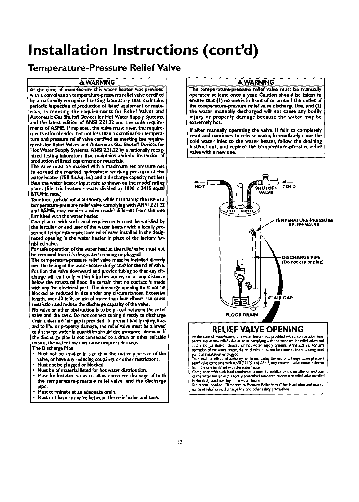
The temperature-pressurereliefvalvemustbe installeddirectly
intothe fittingofthe water heater designatedforthe relief valve.
Positionthe valvedownwardand providetubingsothat anydis-
chargewill exit only within 6 inchesabove, or at anydistance
belowthe structuralfloor. Be certain that no contact ismade
with anyliveelectricalpart. The disthargeopeningmust notbe
blockedor reduced in size underany circumstances.Excessive
length,over 30fe_, or useof more than four elbewscan cause
restriction andreducethe dischargecapacityofthe valve. I
No valveor other obstructionisto be placedbetweenthe relief
valveand the tank. Do not connecttubing directlyto discharge
drainunlessa 6"air gapisprovided.Topreventbodilyinjury,haz-
ardto life,or propertydamage,the relief valvemust beallowed
to dischargewater inquantitiesshouldcircumstancesdemand.If
the dischargepipe isnot connectedto a drain or other suitable
means,the waterflowmaycausepropertydamage.
The DischargePipe:
• Must not be smaller in size than the outlet pipe sizeof the
valve,or haveanyreducing couplingsor other restrictions.
Mustnot be pluggedor blocked.
Mustbeofmaterial listedfor hotwater distribution.
Mustbe installedso asto allow complete drainageof both
the temperature-pressure relief valve, and the discharge
pipe.
Mustterminate at anadequatedrain.
Mustnot haveanyvalvebetween the relief vaJveand tank_
•, WARNING
The temperature-pressure relief valve must be manually
operated at least once a year. Caution should be taken to
ensurethat (I) no one isin front of or around the outlet of
the temperature-pressure relief valvedischargeline, and (2)
the water manually discharged will not cause any bodily
injury or property damage because the water may be
extremely hot.
If after manua/Iy operating the valve, it failsto completely
reset and continuesto release water, immediately closethe
cold water inlet to the water heater, follow the draining
instructions, and replace the temperature-pressure relief
valvewith a newone.
HOT
VALVE
FLOOR DRAIN
COLD
RELIEF VALVE
(Do not cap or plug)
6" AIR GAP
RELIEFVALVEOPENING
At thetime of maflufacture,thiswater heaterwasprovidedwith a combination tem-
perature-pressure_-.IJef valvelisted ascomping withtee standardforrelid va_es_d
automaticgasshut-offdevicesfor hot water supp_ sys_ms,ANSt Z2t.22. Forsafe
operadonof the waterheater,the reliefvaFvemustnot beremovedfromitsdesignated
ffoin¢of installationorfflugged.
Yourlocal urisdictionafauthori_ whilemandatingthe useof a temperature-pressure
relief valvecomplyingwithANSI7.21.22andASNF.n_y r_uire avave mode dfferent
fromthe onefurnishedwiththe waterheart
Comffliancew_h suchlocal_-_uirernen_ rn_st besatisEedbythe installeror enduser
of the waterheaterwitha locallyprescribedtemperature-pressurere{iefv_Neinstalled
in the designatedopeninginthewater heate_
Seemanualheading-_Temperature-PressureReli_ Valves"for installationandmainte-
nanceof relief valve,dischari_eline,andother safetyprecautions.
12
Installation Instructions (cont'd)
Filling the Water Heater
_, CAUTION I
Never usethis water heater unlessit iscompletelyfilledwith
water. Toprevent damageto the tank, the tank must be filledI
with water. Water must flow from the hot water faucet
beforeturn ng ON gasto the water heater.
For properventing in certain installations,a larger diameter vent
pipe may be necessary. Due to great variances in installations,
unforeseeableby the manufacturer of the water heater, you must
consult your gas company to aid you in determining the proper
venting foryourwater heater fromthe vent tablesin the latestedi-
tion of the National FuelGas Code ANSI Z223.1, alsoreferredto
asNFPA 54.
To fill the water heater with water:
• Close the water heater drain valve by turning the handle to
the right (clockwise). The drain valve is on the lower front of
the water heater.
• Open the cold water supply valve to the water heater.
NOTE: The cold water supply valve must be left open
when the water heater is in use.
• To insure complete filling of the tank, allow air to exit by
opening the nearest hot water faucet. Allow water to run
until a constant flow is obtained. This will let air out of the
water heater and the piping.
• Check all new water piping for leaks. Repairas needed.
Venting
_,WARNING
VENT DAMPERS - Any vent damper,whether it isoperated
thermally or otherwisemust beremoved if itsuseinhibitsprop-
erdraftingof the water heater.
Thermally Operated Vent Dampers: Gas-firedwater heaters
havingthermal efficiencyin excessof 80%may producea rela-
tivelylowflue gastemperature.Suchtemperaturesmaynot be
high enough to properly open thermally operated vent
dampers. Thiswould causespillage of fiue gasesand maycause
carbon monoxide poisoning.
Vent dampers must bearevidenceofcertificationascomplying
with the latest edition of American National StandardANSI
Z21.68 (ANSi Z21.66 & 67, respectively,coverelectricallyand
mechanicallyactuatedventdampers).Beforeinstallationofany
vent damper,consultyour localSearsServiceCenter or the gas
utilityfor furtherinformation.
•_ WARNING
To insure proper venting of this gas-firedwater heater, the
correct vent pipe diameter must be utilized.Any additionsor
deletionsofother gasappliancesona common vent with this
water heater may adverselyaffectthe operation of the water
heater. Consultthe localSearsService Center or gasutility if
any suchchangesare planned.
Check the venting system for signs of obstruction or deterioration
and replace if needed.
The combustion and ventilation airflow must not be obstructed.
AWARNING I
Obstructedor deterioratedvent systemsmaypresenta seriousI
healthriskor asphyxiation. [
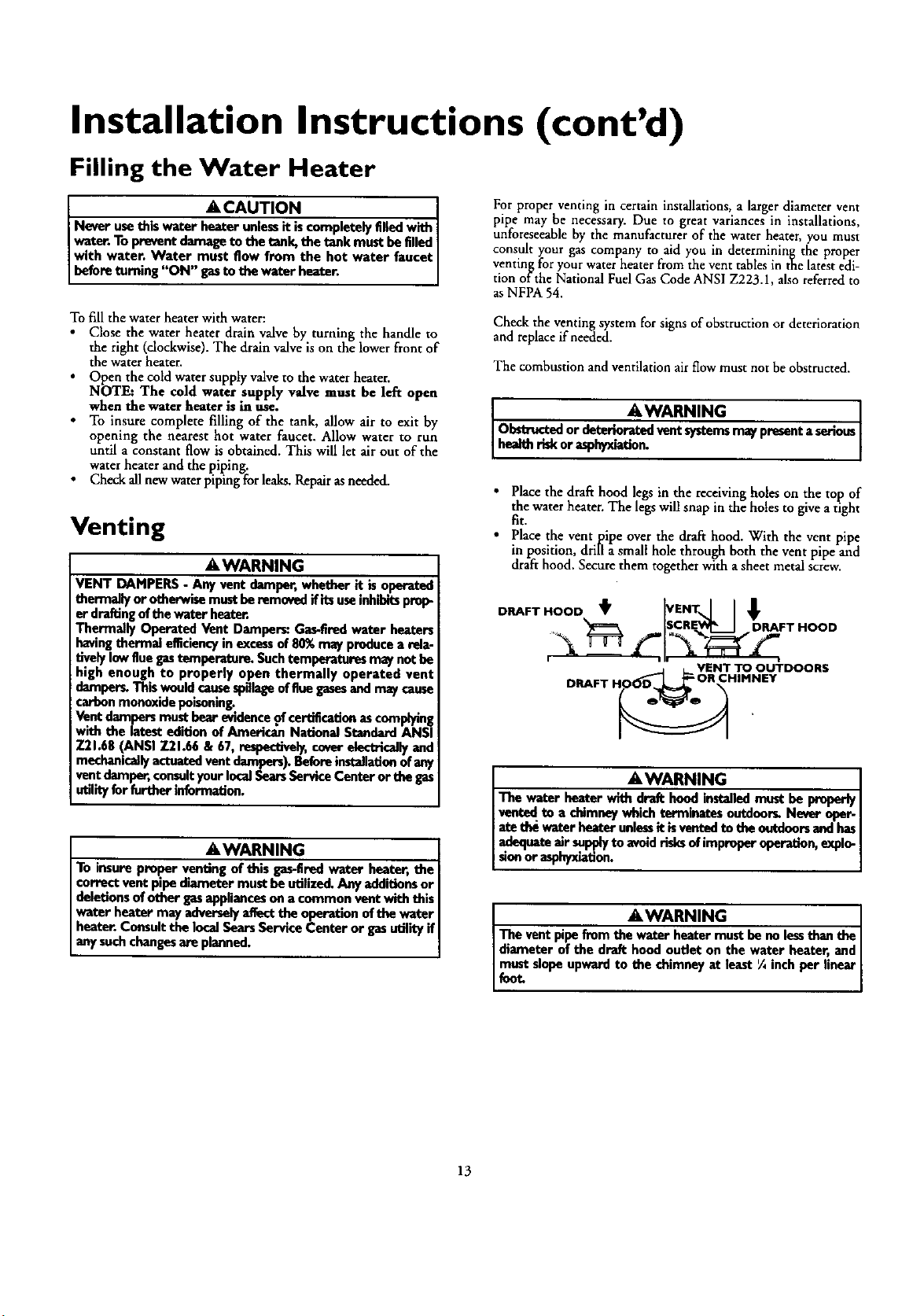
• Place the dra_ hood legs in the receiving holes on the top of
the water heater. The legs will snap in the holes to give a tight
fit.
• Place the vent pipe over the draft hood. With the vent pipe
in position, drill a small hole through both the vent pipe and
draft hood. Secure them together with a sheet metal ;crew.
DRAFT HOOD _ VENT ] I
[SCRE___I DRAFT HOOD
f
VENT TO OUTDOORS
DRAFT HO_ ,ORCHIHNEV
AWARNING J
The water heater with draft hood installedmust be properlyJ
ventedto a chimneywhich terminates outtioor_ Never oper-I
_e the vraterheater unlessit k ventodte the ootdonrsandhasI
adequateair supplyto avoidrisksof improperoperation,explo-I
sionor asphyxiation. ]
AWARNING
The vent pipe from the water heater must be nolessthan the
diameter of the draft hood outlet on the water heater, and
_€_t-tslopeupward to the chimneyat least '/4inchper linear
13
Installation Instructions (cont'd)
Venting (cont'd)
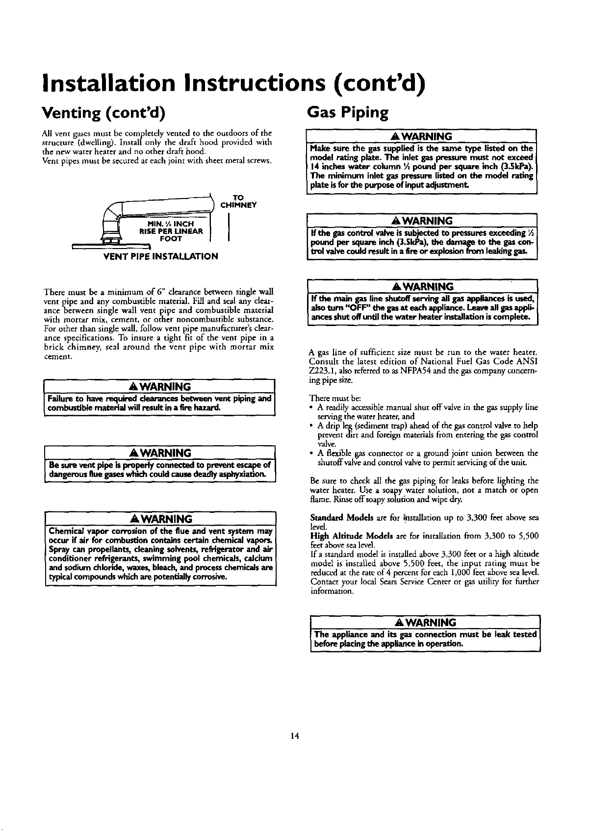
All vent gases must be completely vented to the outdoors of the
structure (dwelling). Installonly the draft hood provided with
the new water heater and no other draft hood.
Vent pipes must be secured at each joint with sheet metal screws.
|
VENT PIPE INSTALLATION
TO
CHIMNEY
Gas Piping
AWARNING
Make sure the gassupplied is the same type listed on the
model rating plate. The inlet gaspressuremust not exceed J
14inches water column Vzpound per square inch (3.5kPa).
The minimum inlet gaspressurelisted on the model rating [
pate isfor the purposeof input adjustment. J
AWARNING I
'the gascontrol valve issubjectedto pressuresexceeding ½]
pound per square inch (3.SkPa),the damage to the gascon- I
trol valvecouldresult in a fire or explosionfT_n leakingge_ I
There must be a minimum of 6" clearance between single wall
vent pipe and any combustible material. Fill and seal any clear-
ance between single wall vent pipe and combustible material
with mortar mix, cement, or other noncombustible substance.
For other than single wall, follow vent pipe manufacturer's clear-
ance specifications. To insure a tight fit of the vent pipe in a
brick chimney, seal around the vent pipe with mortar mix
cement,
&WARNING I
Failure to have required clearancesbetween vent pipingand
combustiblematerial will result ina fire hazard.
AWARNING I
Be surevent pipe isproperly connectedto preventescapeof
! dangerousflue gaseswhichcouldcausedeadlyasphyxiation.
AWARNING
Chemical vapor corrosion of the flue and vent system may
occur if air for combustioncontainscertain chemicalvaper_
Spray can propellants,cleaningsolvents,refrigerator and air
conditioner refrigerants, swimming pool chemicals,calcium
andsodium chloride,waxes,bleach,and processchemicalsare
typicalcompoundswhichare potentiallycorrosive.
&WARNING ]
Ifthe maingasline shuix_servingall gasappliancesk used,|
alsoturn"OFF" thegasateachappliance.Leaveall gasappli-|
ancesshutoR'untilthewaterheaterinstallationiscomplete,|
A gas line of sufficient size must be run to the water heater.
Consult the latest edition of National Fuel Gas Code ANSI
Z223.1, also referred to asNFPA54 and the gas company concern-
ing pipe size.
There must be:
• A readily accessible manual shut off valve in the gas supply line
serving the water heater, and
• A drip leg (sediment trap) ahead of the gas control valve to help
prevent dirt and foreign materials from entering the gas control
V'dlve.
• A flexible gas connector or a ground joint union between the
shutoffvalve and control valve to permit servicing of the unit.
Be sure to check all the gas piping for leaks before lighting the
water heater. Use a soapy water solution, not a match or open
flame. Rinse offsoapy solution and wipe dr_
Standard Modds are for _stallation up to 3,300 feet abovesea
level.
High Altitude Models are for installationfrom 3,300 to 5,500
feetabovesealevel.
If a standard model is installedabove3,300 feetor a high altitude
mode1 is installed above 5,500 feet, the input rating must be
reducedat the rateof4 percentfor each1,000 feetabovesealevel.
Contact your local SearsServiceCenter or gasutility for further
information.
AWARNING I
The applianceand itsgasconnectionmustbe leaktested
beforepacingtheapplancenoperation.
14
Installation Instructions (cont'd)
AWARNING
• The applianceand its individualshutoffvalvemustbe discon.
nected from the gassupplypipingsystemduringanypressure
testing of the gas system at test pressuresin excessof '/2
poundper squareinch(3.5kPa).
• The appliancemustbe isolatedfrom the gassupplypipingsys-
tem byclosingits individualmanual shutoff valve duringany
pressuretesting of the gassupplypiping systemat test pres-
soresequalor lessthan _ poundper squareinch(3.5kPa).
J AWARNING -1
Use pipe joint compound or teflon tape marked as being[
resistantto the acldonofpoUoleum [Propane(LR)] gase_ [
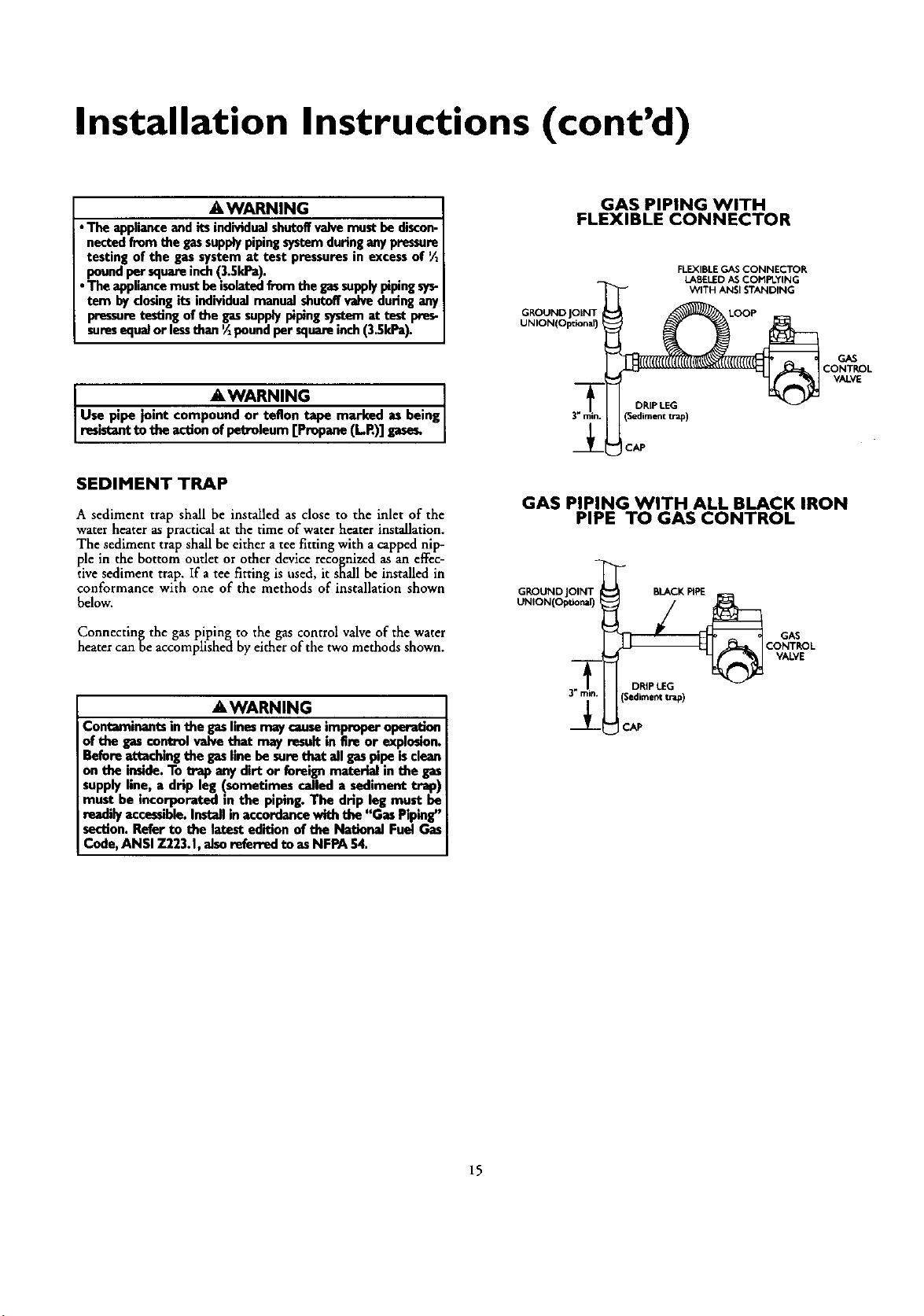
SEDIMENT TRAP
A sediment trap shall be installed as close to the inlet of the
waterheater as practical at the time of waterheater installation.
The sediment trap shall beeither a tee fitting with a capped nip-
ple in the bottom outlet or otherdevice recognizedas an effec-
tivesediment trap. If a tee fitting is used, it shall be installedin
conformance with one of the methods of installation shown
below.
Connectin_ the gaspiping to the gas control valveof the water
heater canoe accomplishedby either of the twomethods shown.
&WARNING
Contaminants in the gaslinesmay causeimproper operation
of the gascontrol valve that may result in fire or explosion.
Before attaching the gasline be sore that ell gaspipe isclean
on the inside.To trap any dirt or foreign materiel in the gas
supply line, a drip leg (sometimes called a sediment trap)
must be incorporated in the piping. The drip leg must be
readilyaccessible.Installin accordance with the "Gas Piping"
section. Refer to the latest edition of the National Fuel Gas
Code, ANSI 7.223.1,also referred to as NFPA 54.
GAS PIPING WITH
FLEXIBLE CONNECTOR
GKOUND
UNION(OlXional)
FLEXIBLE GAS CONNECTOR
LABELED AS COt'IPLYING
WITH ANSI STANDING
DRIPLEG
(Sedimenttrap)
ICAP
GAS PIPING WITH ALL BLACK IRON
PIPE TO GAS CONTROL
GROUND JOINT BLACK PIPE
UNION(Optional)
GAS
CONTROL
VALVE
GAS
CONTROL
VALVE
15
Installation Instructions (cont'd)
Installation Checklist
BEFORE LIGHTING THE PILOT:
• Check the gas lines for leaks.
a. Use a soapy water solution. DO NOT test for gas leaks
usinga match or open flame.
b. Brush the soapy water solution on all gas pipes, joints and
fittings.
c. Check, for bubbling soap. This means you have a leak.
Turn OFF gas andmake the necessary repairs.
d. Recheck for leaks.
e. Rinse offsoapy solution and wipe dry.
• Is the new temperature-pressure relief valve properly installed
and piped to an adequate drain? See "Temperature-Pressure
Relief Valve" section.
. Are the cold and hot water lines connected to the water
heater correctly? See "Water Piping" instructions in the
"Installation Instructions _ section.
• Is the water heater completely filled with water? See _Filling"
instructions in the _Installation Instructions" section.
• Will a water leak damage anything? See the "Facts to
Consider About the Location" section.
• Is there proper clearance between the water heater and any-
thing that mtght catch fire. See the Facts to Cons]der About
the Location" section.
• Do you have adequate ventilation so that the water heater
will o,p_,rate properly? See Combustion Air and Ventilation
in the Installation Instructions section•
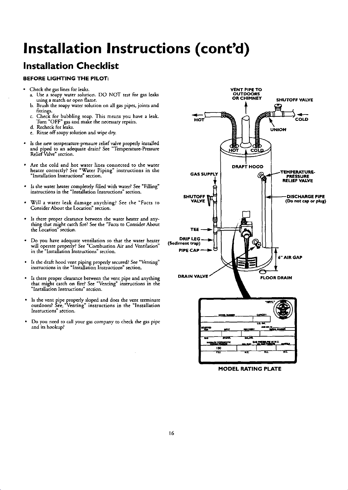
HOT
GAS SUPPLY
SHUTOFF
VALVE I
TEE
(Sediment trap)
PIPE CAP
VENT PIPE TO
OUTDOORS
OR CHIMNEY
t
DRAFT HOOD
SHUTOFF VALVE
COLD
UNION
• Is the draft hood vent piping properly secured? See "Venting"
instructions in the "Installation Instructions" section.
• Is there proper clearance between the vent pipe and anything
that might catch on fire. See Venting mstrucnons m the
"Installation Instructions" section.
• Is the vent pipe properly sloped and does the vent terminate
outdoors. See: Venting msttuctions m the Installat*on
Instructions" section.
• Do you need to call your gas company to check the gas pipe
and its hookup?
,,0 I I I
•aLt w._ wg¢ W_,
I
MODEL RATING PLATE
PRESSURE
RELIEF VALVE
PIPE
(Do not cap or plug)
16
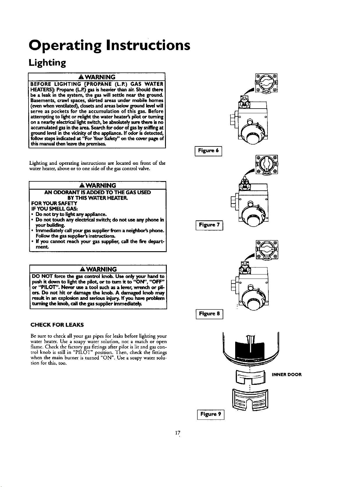
Operating Instructions
Lighting
AWARNING
BEFORE LIGHTING [PROPANE (L.P.) GAS WATER
HEATERS]:Propane(L.R) gasis heavierthan air. Shouldthere
be a leak in the system,the gaswill settle near the ground.
Basements,crawl spaces,skirted areas under mobile homes
(evenwhen ventilated),closetsandareasbelow groundlevelwill
serve as pockets for the accumulation of this gas. Before
attempting to lightor relightthe water heater'spilotor turning
on anearbyelectricallight switch,be absu4utelysurethem isno
accumulatedgasinthe area.Searchfor odorofgasbysniffingat
groundlevelin the vicinityofthe appliance.Ifodor isdetected,
followstepsindicatedat "For YourSafety"onthe coverpageof
this manual thenieavethe premise_
Lightingand operatinginstructions arelocated on front of the
waterheater, aboveor to one side ofthe gascontrol valve.
AWARNING
AN ODORANT ISADDED TO THE GAS USED
BY THIS WATER HEATER.
FOR YOUR SAFETY
IF YOU SMELL GAS:
Do not try to light anyappliance.
Do nottouch anyelectricalswitch;do not useanyphone in
your building.
Immediately callyour gassupplierfrom a neighbor'sphone.
Followthe gassuppliers instruction_
If you cannot reach your gassupplier, callthe fire depart-
ment
AWARNING
DO NOT forcethe gascontrol knob. Use only your hand to
rashit down to light the pilot, or to turn it to "ON", "OFF"
or "PILOT". Never usea tool such as a lever,wrench or pli-
er_ Do not hit or damage the Imob. A damaged Imob may
result in an explosionand seriousinjury. If you haveproblem
turningthe knob,callthe gassupplier immediately.
CHECK FOR LEAKS
Be sure to check all your gas pipes for leaksbefore lightingyour
waterheater. Use a soapy water solution, not a match or open
flame. Check the factorygas,_ttingsafter pilot is lit and gascon-
trol knob is still in PILOT position,.,Then, check the fittings
when the main burner is turned ON . Use a soapy water solu-
tion forthis, too.
Figure 6 ]
I Figure 8 1
I Figure 9 ]
INNER DOOR
17
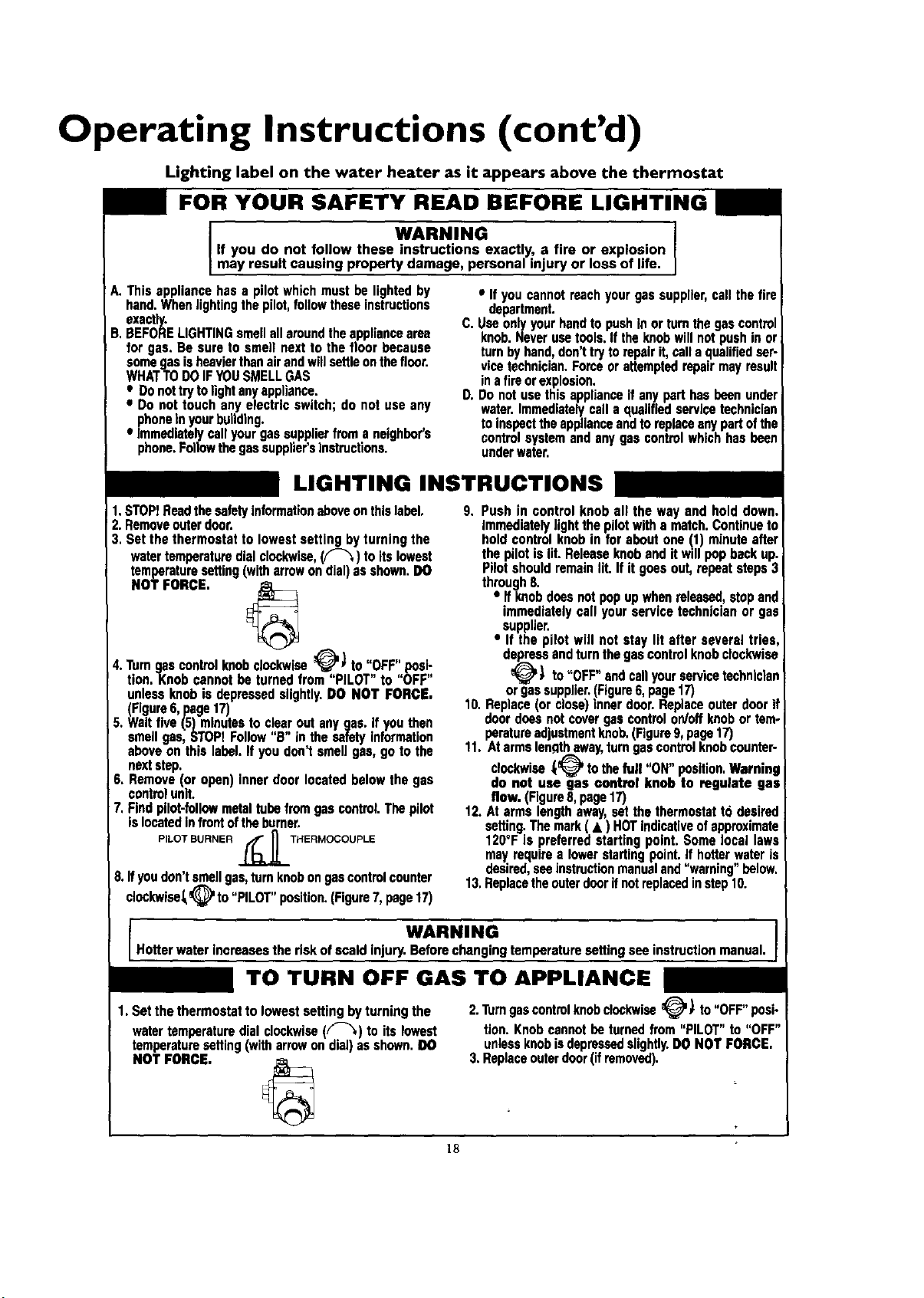
Operating Instructions (cont'd)
Lighting label on the water heater as it appears above the thermostat
FOR YOUR SAFETY READ BEFORE LIGHTING
WARNING
If you do not follow these instructions exactly, a fire or explosion
may result causing property damage, personal injury or loss of life.
A.Thisappliancehasa pilotwhichmust belightedby
hand.Whenlightingthepilot,followtheseinstructions
exactly.
B,BEFORELIGHTINGsmellallaroundtheappliancearea
for gas.Besureto smellnexttothefloor because
somegasisheavierthanairandwillsettleonthefloor.
WHATTODOIFYOUSMELLGAS
• Donottrytolightanyappliance.
• Donottouchanyelectricswitch;do notuseany
phoneinyourbuilding.
• Immediatelycallyourgassupplierfroma neighbor's
phone.Followthegassupplier'sinstructions.
C,
D.
• Ifyoucannotreachyourgassupplier,callthefire
department.
Usaonlyyourhandtopushinorturnthegascontrol
knob.Neverusatools.If theknobwillnotpushinor
turnbyhand,don'ttrytorepairit,calla qualifiedser-
vicetechnician.Forceorattemptedrepairmayresult
inafireorexplosion.
Donotusethisapplianceifanyparthasbeenunder
water.Immediatelycalla qualifiedservicetechnician
toinspecttheapplianceandtoreplaceanypad ofthe
controlsystemandanygascontrolwhichhasbeen
underwater.
LIGHTING INSTRUCTIONS
1.STOPIReadthesafetyinformationaboveonthislabel.
2.Removeouterdoor.
3. Setthethermostatto lowestsettingbyturningthe
watertemperaturedialclockwise,(F-_) toitslowest
temperaturesetting(witharrowondial)asshown.DO
NOT FORCE.
4.Turngascontrolknobclockwise__,, ) to ",OFF'I,pos_
tion,Knob cannotbe turnedfrom PILOT to OFF
unlessknobis depressedslightly.DO NOT FORCE.
(Figure6,page17)
5. Waitfive(5)minutestoclearoutanygas.ifyouthen
smellgas,STOPIFollow"B"inthesafetyinformation
aboveonthislabel.If youdon'tsmellgas,gotothe
nextstep.
6, Remove(or open)innerdoorlocatedbelowthegas
controlunit.
7,Findpilot-followmetaltubefromgascontrol.Thepilot
islocatedinfrontoftheburner,
PILOT BURNER ._THERMOCOUPLE
8.Ifyoudon'tsmellgas,turnknobongascontrolcounter
clockwlse,_@ to"PILOT"position,(Figure7,page17)
9. Pushin controlknoball the wayand holddown.
immediatelylightthepilotwitha match.Continueto
holdcontrolknobin foraboutone(1)minuteafter
thepilotislit.Releaseknobanditwillpopbackup.
Pilotshouldremainlit.If itgoesout,repeatsteps3
through8.
• Ifknobduesnotpopupwhenreleased,stopand
immediatelycall yourservicetechnicianor gas
supplier.
• If thepilot willnot staylit after severaltries,
depressandturnthegascontrolknobclockwise
_(_ to"OFF"andcallyourservicetechnician
orgassupplier.(Figure6,page17)
10.Replace(or close)innerdoor.Replaceouterdoorif
doorduesnotcovergascontrolon/offknobor tem-
peratureadjustmentknob,(Rgure9,page17)
11.Atarmslen_qthaway,turngascontrolknobcounter-
clockwise(_ tothefull "ON"position,Warning
do not use gas control knobto regulate gas
flow.(Rgure8,page17)
12.Atarmslengthaway,setthethermostatto desired
setting.Themark(• ) HOTindicativeofapproximate
120°Fis preferredstartingpoint.Somelocallaws
mayrequirea lowerstadingpoint.If hotterwateris
desired,seeinstructionmanualand"warning"below,
13,Replacetheouterdoorifnotreplacedinstep10.
WARNING
Hotterwaterincreasestheriskofscaldinjury.Beforechangingtemperaturesettingseeinstructionmanual.
TO TURN OFF GAS TO APPLIANCE
1.Setthethermostatto lowestsettingbyturningthe
watertemperaturedialclOckwise(F'_) toitslowest
temperaturesetting(witharrowondial)asshown.DO
NOT FORCE.
2.Turngascontrolknobclockwise_V ) to "OFF" posi-
tion. Knob cannot be turned from "PILOT" to "OFF"
unlessknobisdepressedslightly.DO NOT FORCE,
3. Replaceouterdoor(if removed).
18
Operating Instructions (cont'd)
Temperature Regulation
Due to the nature of the typical gas water heater, the water tem-
{_oeraturein certain situations may vary up to 30°F higher or
wer at the point of use such as, bathtubs, showers, sink, etc.
This means that when the temperature adjustment dial is set at
the mark approximating 1200F, the actual water temperature at
any hot water tap could be as high as 150°F or as low as 90*E
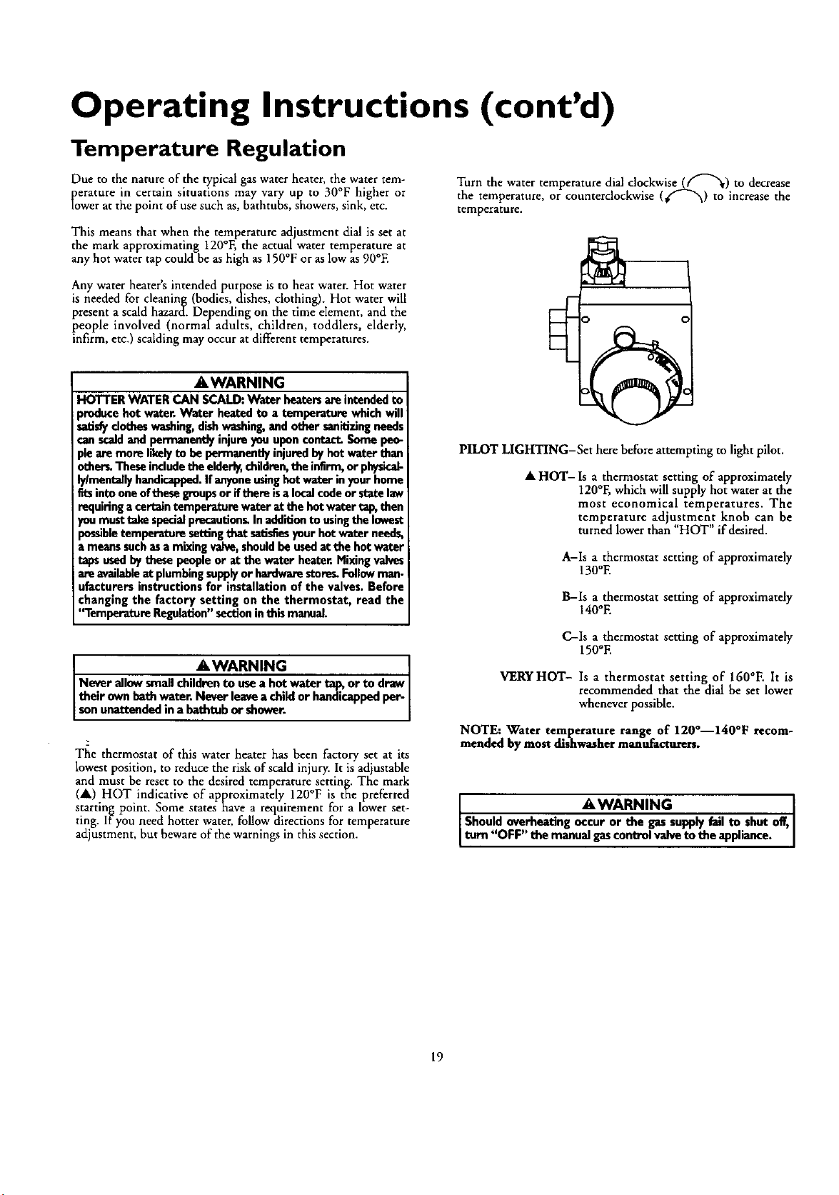
Turn the water temperature dial clockwise (_--'_) to decrease
the temperature, or counterclockwise (_"_) to increase the
temperature.
Any water heater's intended purpose is to heat water. Hot water
is needed for cleaning (bodies, dishes, clothing). Hot water will
present a scald hazard. Depending on the time element, and the
people involved (normaladults, children, toddlers, elderly,
infirm, etc.) scalding may occur at different temperatures.
A, WARNING
HOTTER WATERCAN SCALD:Water heatersare intendedto
producehot water.Water heatedto a temperature whichwill
satisfydotheswashing,dishwashing,and other sanitizingneeds
canscaldandpermanentlyinjureyouuponcontact.Somepen-
pieare more likelyto be permanently injuredbyhot water than
other_Theseincludethe elderly,children,the infirm,or physica_
ly/mantelly handicapped.If anyoneusinghotwater inyour home
fitsintooneof thesegroupsor ifthere isalocalcodeor statelaw
requiringacertaintemperatomwater at the hot water _ then
_u musttake specialprecautionLIn additionto usingthe lowest
_esibletemperature settingthat satisfiesyour hotwater needs,
Lmeanssuchasa mixingvalve,shouldbe usedat the hotwater
tapsusedbythese peopleor at the water heater.Mixingvalves
are availableat plumbingsupplyor hardwarestore_Followman-
ufacturers instructions for installation of the valves. Before
changing the factory setting on the thermostat, read the
"Temperature Regulation"sectioninthis manual.
AWARNING
Never allow smallchildren to usea hot water _ or to draw
their ownbath water. Never leavea childor handicappedper-
sonunattended ina bathtub or shower.
2
The thermostat of this water heater has been factory set at its
lowest position, to reduce the risk of scald injury. It is adjustable
and must be reset to the desired temperature setting. The mark
(•) HOT indicative of approximately 120°F is the preferred
starting point. Some states have a requirement for a lower set-
ting. lfyou need hotter water, follow directions for temperature
adjustment, but beware of the warnings in this section.
PILOT LIGHTING-Set here before attempting to light pilot.
• HOT- Is a thermostat setting of approximately
120°F, which will supply hot water at the
most economical temperatures. The
temperature adjustment knob can be
turned lower than "HOT" if desired.
A-Is a thermostat setting of approximately
130°E
B-Is a thermostat setting of approximately
140°E
C-Is a thermostat setting of approximately
150°E
VERYHOT- Is a thermostat setting of 160°F. It is
recommended that the dial be set lower
whenever possible.
NOTE: Water temperature range of 1200--1400F recom-
mended by most dishwasher manufacturers.
AWARNING [
Shouldoverheatingoccuror the gassupplyfailto shut off,]
Itom "OFF" themanualgascontrolvalvetotheappliance. ]
19
Service and Adjustment
Tank (Sediment) Cleaning
Sediment build-up on the tank bottom may create varying
amounts of noise, and if left in the tank will cause premature
rank failure. In some water areas, you may not be able to drain
all sediment deposits by simply draining the tank. In these cases
Mag-Erad (part no. 23600) can be used to help remove the sedi-
ment deposits. This may be ordered from the ,Sears Service
Center. For ordering, refer to the Parts Order List section.
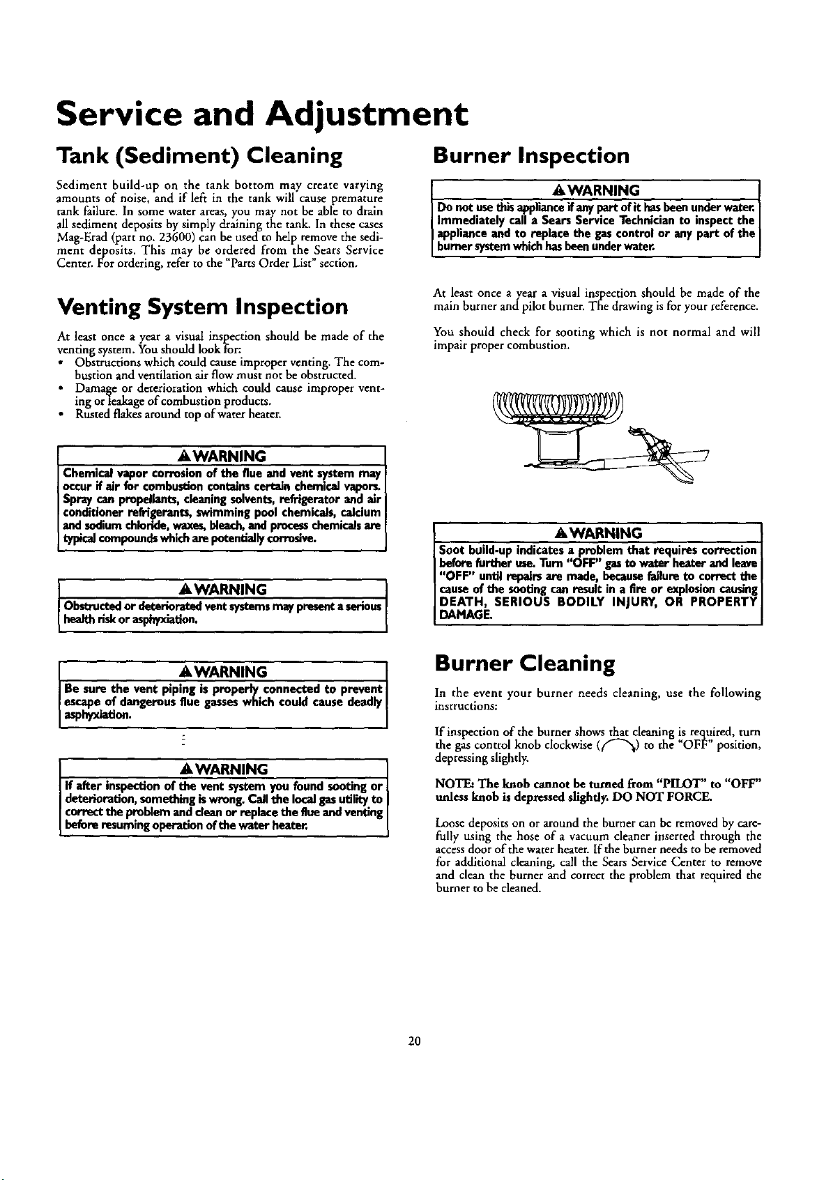
Burner Inspection
&WARNING I
Do not usethisapplianceif anypart of it hasbeenunder water,
Immediately calla Sears Service Technician to inspect the
appliance and to replace the gascontrol or any part of the
burner systemwh chhasbeenunderwater.
Venting System Inspection
At least once a year a visual inspection should be made of the
venting system. You should look for:
• Obstructions which could cause improper venting. The com-
bustion and ventilation airflow must not be obstructed.
i Damage or deterioration which could cause improper vent-
ing orleakage of combustion products.
Rusted flakes around top of water heater.
At least once ayear a visual inspection should be made of the
main burner andpilot burner. The drawing is for your reference.
You should check for sooting which is not normal and will
impair proper combustion.
&WARNING
Chemical vapor corrosionof the flue and vent system may
occurif air for combustionconi_Jnscertain chemicalvapors.
Spray can propallant_,cleaning solvents,refrigerator and air
conditioner refrigerants, swimming pool chemicals, calcium
andsodiumchloride,waxes,bleach,and processchemicalsare
typicalcompoundswhichare potendaily corrosive.
AWARNING ]
Ob_ucted or deterioratedvent systemsmaypresenta serious
heal_ riskor asphyxation.
AWARNING I
Be sure the vent pip_onnected to prevent
escape of dangerousflue gesseswhich could cause deadly
asphyxiation.
&WARNING I
If after inspection of the vent system you found sooting or
deterioration, something iswrong. Call the localgasutility to I
correct the problem and cleanor replace the flue andventing
beforeresum ngoperation of the water heater.
&WARNING
Soot build.up indicates a problem that requires correction
beforefurther use.Turn "OFF" gasto water heater and leave
"OFF" until repairsare made, becausefailureto correct the
causeof the sootingcan result in a fire or explosioncausing
DEATH, SERIOUS BODILY INJURY, OR PROPERTY
DAMAGE.
Burner Cleaning
In the event your burner needs cleaning, use the following
instructions:
If inspection of the burner shows that cleaning _ re_,u,ired, turn
the gas control knob clockwise (_",_) to the OFF position,
depressing slightly.
NOTE:The knob cannot be turned fi'om "PILOT" to "OFF"
unless knob is depressedslightly. DO NOT FORCE.
Loose deposits on or around the burner can be removed by care-
fully using the hose of a vacuum cleaner inserted through the
access door of the water heater. If the burner needs to be removed
for additional cleaning, call the Sears Service Center to remove
and clean the burner and correct the problem that required the
burner to be cleaned.
20
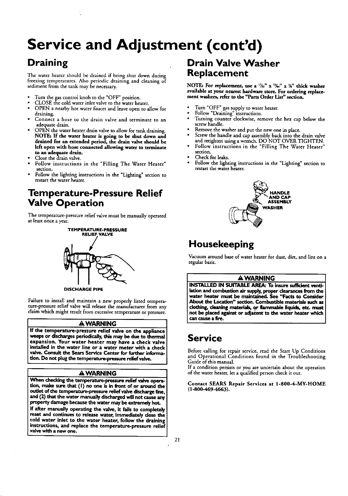
Service and Adjustment (cont'd)
Draining
The water heater should be drained if being shut down during
freezing temperatures. Also periodic draining and cleaning of
sediment from the tank may be necessary.
Turn the gas control knob to the "OFF" position.
CLOSE the cold water inlet valve to the water heater.
• OPEN a nearby hot water faucet and leave open to allow for
draining.
• Connect a hose to the drain valve and terminate to an
adequate drain.
• OPEN the water heater drain valve to allow for tank draining.
NOTE: If the water heater is going to be shut down and
drained for an extended period, the drain valve should be
left open with hose connected allowing water to terminate
to an adequate drain.
• Close thedrainvalve.
• Follow instructions in the "Filling The Water Heater"
section.
• Follow the lighting instructions in the "Lighting" section to
restart the water heater.
Drain Valve Washer
Replacement
NOTE: For replacement, use atT,, x "/_" x %" thick washer
available at your nearest hardware store. For ordering replace-
ment washers, refer to the "Parts Order List" section.
Turn "OFF" gas supply to water heater.
Follow "Draining" instructions.
Turning counter clockwise, remove the hex cap below the
screw handle.
Remove the washer and put the new one in place.
Screw the handle and cap assembly back into the drain valve
and retighten using a wrench. DO NOT OVER TIGHTEN.
Fol!ow instructions in the Filling The Water Heater"
section.
Check for leaks.
Follow the lighting instructions in the "Lighting" section to
restart the water heater.
Temperature-Pressure Relief
Valve Operation
The temperature-pressure relief valve must be manually operated
at least once a year.
TEMPERATURE-PRESSURE
REL_VALVE
ASSEMBLY
WASHER
Housekeeping
Vacuum around base of water heater for dust, dirt, and lint on a
regular basis.
DISCHARGE PIPE
Failure to install and maintain a new properly listed tempera-
ture-pres,sure relief valve will release the manufacturer from any
claim which might result from excessive temperature or pressure.
A WARNING
If the temperature-pressure relief valve on the appliance
weepsor dischargesperiodically,this may be due to thermal
expansion. Your water heater may have a check valve
installed in the water line or a water meter with a check
valve. Consult the SearsService Center for further informa-
tion. Do not plugthe temperature-pressure relief valve.
&WARNING
When checkingthe temperature-pressure reliefvalve opera-
tion, make sure that (I) no one isin front of or around the
outlet of the temperature-pressure reliefvalve dischargeline,
and (2) that the water manuallydischargedwill not causeany
property damage becausethe water may be extremely hot.
If after manually operating the valve, it fails to completely
reset and continuesto release water, immediately close the
cold water inlet to the water heater, follow the draining
instructions, and replace the temperature.pressure relief
valve with a new one.
AWARNING
INSTALLED IN SUITABLE AREA: To insuresutTwiantvantt-
latian andcombustion"air supply,,peoper dem-,u_es,from the
water beater must be maintained. See Facts to Consider
About the Location" section.Combustible materials such as
clothing, cleaning materials, or flammable liquids,et_ must
not be placedagainstor adjacentto the water heater which
can ceuse a fire.
Service
Before calling for repair service, read the Start Up Conditions
and Operational Conditions found in the Troubleshooting
Guide of this manual.
If a condition persists or you are uncertain about the operation
of the water heater, let a qualified person check it out.
Contact SEARS Repair Services at 1-800-4-MY-HOME
(1-800-469-4663).
21
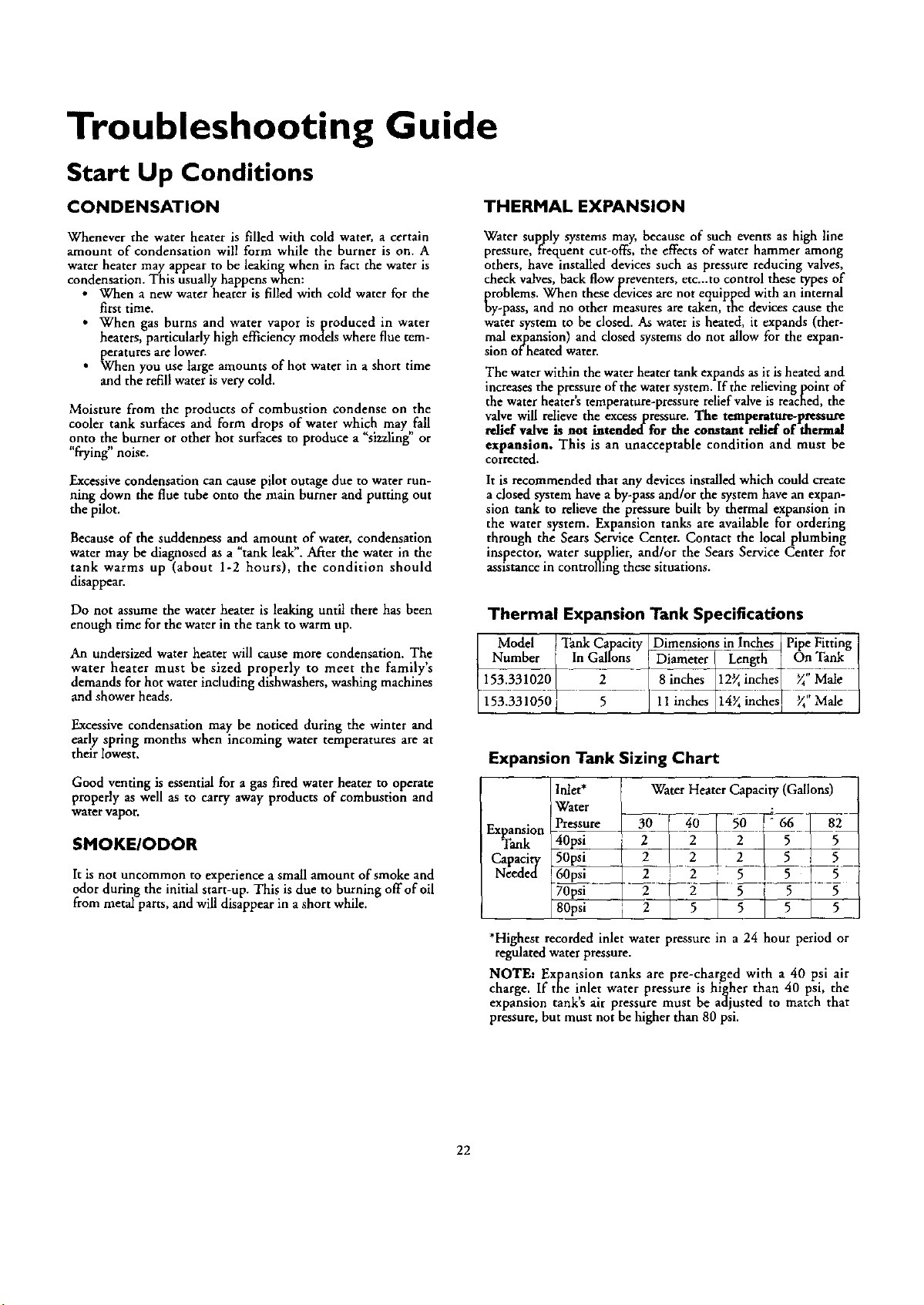
Troubleshooting Guide
Start Up Conditions
CONDENSATION THERMAL EXPANSION
Whenever the water heater is filled with cold water, a certain
amount of condensation will form while the burner is on. A
water heater may appear to be leakingwhen in fact the water is
condensation. This usually happens when:
• When a new water heater is filled with cold water for the
first time.
• When gas burns and water vapor isproduced in water
heaters, particularly high efficiency models where flue tem-
peratures are lower.
• When you use large amounts of hot water in a short time
and the refill water is very cold.
Moisture from the products of combustion condense on the
cooler tank surfaces and form drops of water which may fall
onto the burner or other hot surfaces to produce a "sizzling" or
"frying" noise.
Excessive condensation can cause pilot outage due to water run-
ning down the flue tube onto the main burner and putting out
the pilot.
Because of the suddenness and amount of water, condensation
water may be diagnosed as a "tank leak". After the water in the
tank warms up (about 1-2 hours), the condition should
disappear.
Water supply systems may, because of such events as high line
pressure, frequent cut-offs, the effects of water hammer among
others, have installed devices such as pressure reducing valves,
check valves, back flow preventers, etc...to control these types of
problems. When these devices are not equipped with an internal
by-pass, and no other measures are taken, the devices cause the
water system to be dosed. As water is heated, it expands (ther-
mal expansion) and closed systems do not allow for the expan-
sion of heated water.
The water within the water heater tank expands as it is heated and
increases the pressure of the water system. If the relieving point of
the water heater's temperature-pressure relief valve is reached, the
valve will relieve the excess pressure. The temperature-pressure
relief valve is not intended for the constant relief of thermal
expansion. This is an unacceptable condition and must be
corrected.
It is recommended that any devices installed which could create
a dosed system have a by-pass and/or the system have an expan-
sion tank to relieve the pressure built by thermal expansion in
the water system. Expansion tanks are available for ordering
through the Sears Service Center. Contact the local plumbing
inspector, water supplier, and/or the Sears Service Center for
assistance in controlling these situations•
Do not assume the water heater is leaking until there has been
enough time for the water in the tank to warm up.
An undersized water heater will cause more condensation. The
water heater must be sized properly to meet the family's
demands for hot water including dishwashers, washing machines
and shower heads.
Excessivecondensation may be noticed during the winter and
early spring months when incoming water temperatures are at
their lowest.
Good venting is essential for a gas fired water heater to operate
properly as well as to carry away products of combustion and
water vapor.
SMOKE/ODOR
It is not uncommon to experience a small amount of smoke and
odor during the initial start-up. This is due to burning off of oil
from metal parts, and will disappear in a short while.
Thermal Expansion Tank Specifications
Model JjTank Capacity JDimensions in_ Pipe Fitting
Number In Gallons _et_r _n__ On "Fank
153.331020 2 [ 8inches _12_in_:h_ y'_"Male
153.331050 5 / 11 inches 14_inches I _"Male
Expansion Tank Sizing Chart
Expansion
Tank
Capacity
Needed
Inlet*
IWater
Pressure
40jA
50psi
60psi
70Fsi
80psi
Water Heater Capacity (Gallons)
2 [ 2 [ 2 [ 5 , 5
7 L5-
2 | 5 5 5 5
*Highest recorded inlet water pressure in a 24 hour period or
regulated water pressure.
NOTE: Expansion tanks are pre-charged with a 40 psi air
charge. If the inlet water pressure is higher than 40 psi, the
expansion tank's air pressure must be adjusted to match that
pressure, but must not be higher than 80 psi.
22
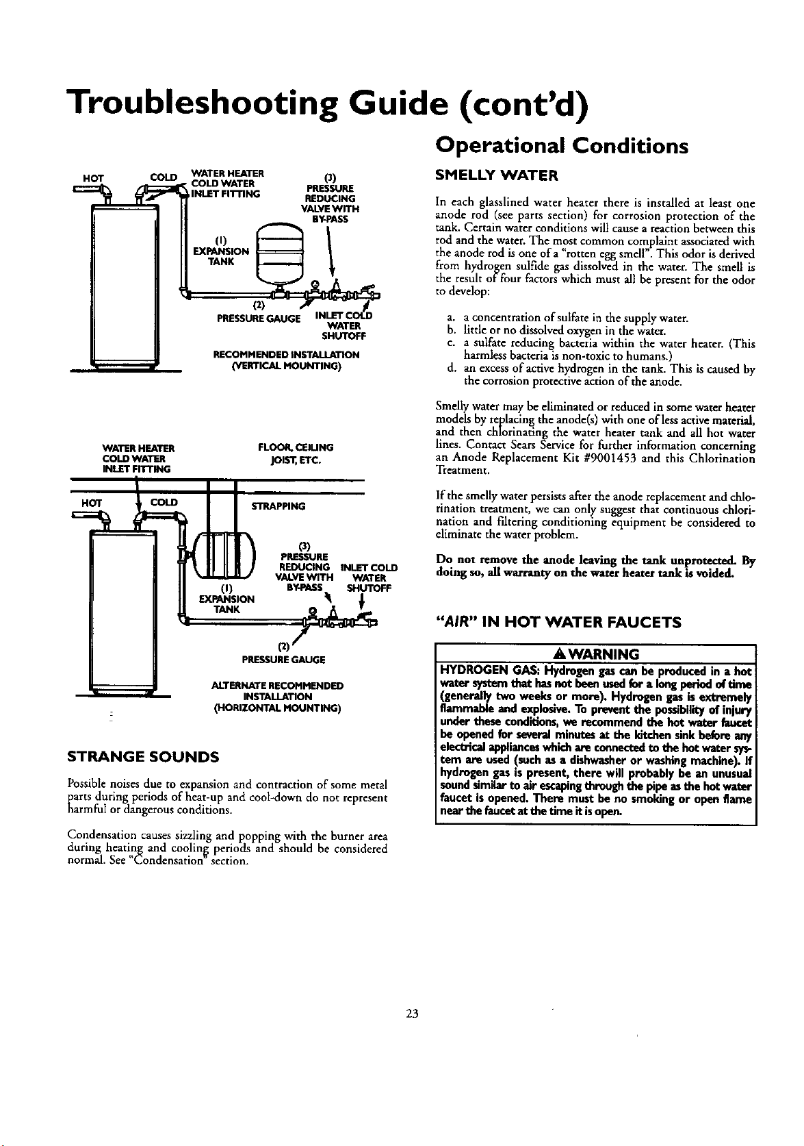
Troubleshooting Guide (cont'd)
Operational Conditions
HOT COLD
WATER HEATER (3)
• COLD WATER PRESSURE
INLET FI'I-rlNG REDUCING
VALVE WITH
BY-PASS
,,, I
EXT_NNEKON _
PRESSURE GAUGE INLET COf.D
WATER
SHUTOFF
RECOMMENDED INSTALLATION
(VERTICAL MOUNTING)
SMELLY WATER
In each glasslined water heater there is installed at least one
anode rod (see parts section) for corrosion protection of the
tank. Certain water conditions will cause a reaction between this
rod and the water. The most common complaint associated with
[h • ¢¢ , . . .
e anode rod is one of a rotten egg smell . This odor ,s derived
from hydrogen sulfide gas dissolved in the water. The smell is
the result of four factors which must all be present for the odor
to develop:
a. a concentration of sulfate in the supply water.
b. little or no dissolved oxygen in the water•
c. a sulfate reducing bacteria within the water heater. (This
harmless bacteria is non-toxic to humans.)
d. an excess of active hydrogen in the tank• This is caused by
the corrosion protective action of the anode.
WATER HEATER
COLD WATER
INLET FITTING
FLOOR, CElUNG
jols'_,ETC.
Smelly water may be eliminated or reduced in some water heater
models by replacing the anode(s) with one of less active material,
and then chlorinating the water heater tank and all hot water
lines. Contact Sears Service for further information concerning
an Anode Replacement Kit #9001453 and this Chlorination
T[eatment.
HOT COLD
STRAPPING
(i)
EXPANSION
0)
PREssuRE
REDUCING INLETCOLD
VALVEWITH WATER
BY-PASS SHUTOFF
PRESSUREGAUGE
ALTERNATE RECOMMENDED
INSTALLATION
(HORIZONTAL MOUNTING)
STRANGE SOUNDS
Possible noises due to expansion and contraction of some metal
Karts during periods of heat-up and cool-down do not represent
armful or dangerous conditions.
Condensation causes sizzling and popping with the burner area
during heating and cooling periods and should be considered
normal• See "Condensation" section.
lfthe smellywater persists afterthe anodereplacementand chlo-
rination treatment, we can only suggest that continuous chlori-
nation and filtering conditioning equipment be considered to
eliminate the water problem.
Do not removethe anode leaving the tank unprotected. By
doing so, all warranty on the water heatertank is voided.
"AIR" IN HOT WATER FAUCETS
AWARNING
HYDROGEN GAS: Hydrogen gascan be producedin a be4
water systemthat hasnot beenused_r a longperiodof tirm
(generally two weeks or more). Hydrogen gasis extremel_
flammable and explosive.To prevent the possibilityof injur_
under these conditions,we recommend the hot water fauce
be openedfor severalminutesat the kitchensinkbefore any
electricalapplianceswhichare connectedto the hot water sys-
tem are used(suchas a dishwasheror washing machine).If
hydrogengas is present, there will probably be an unusual
soundsimilarto air escapingthrough the pipe as the hotwater
faucet isopened. There must be no smoking or open flame
nearthe faucetat the time it isopen.
23
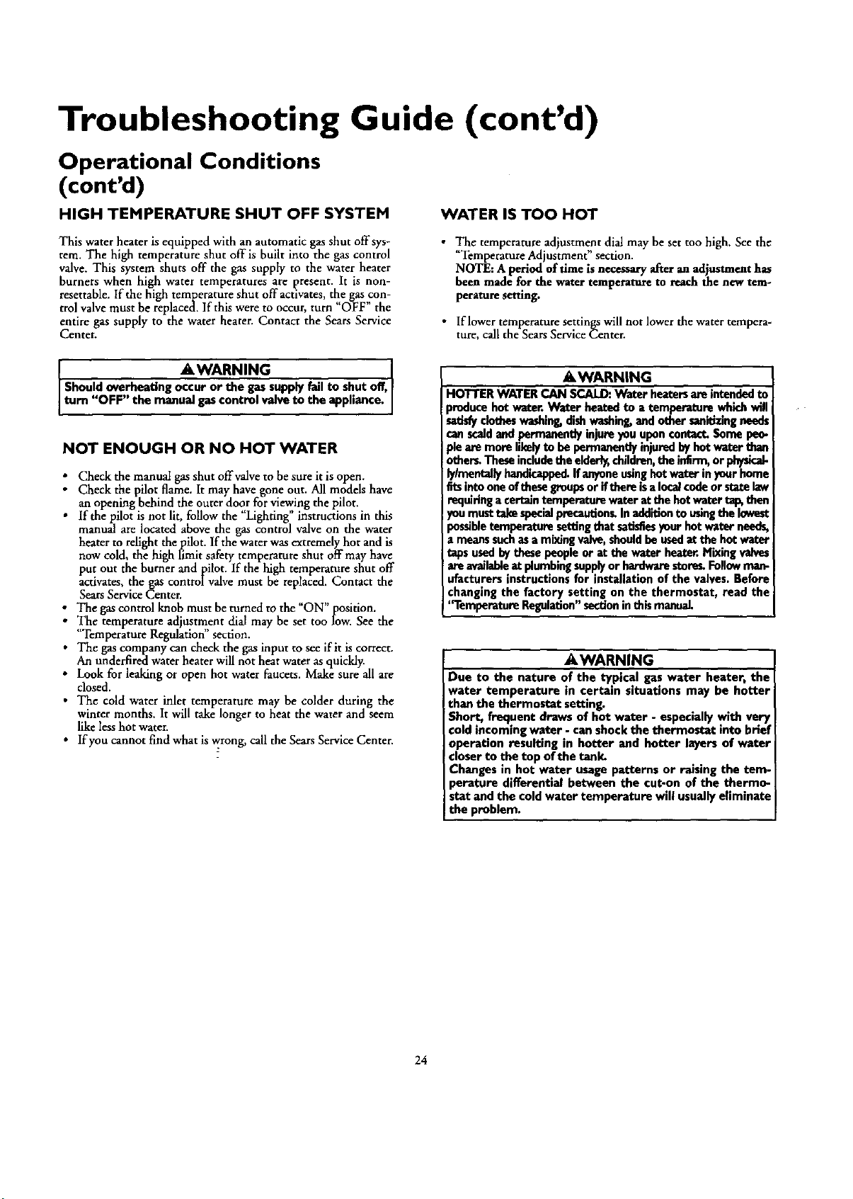
Troubleshooting Guide (cont'd)
Operational Conditions
(cont'd)
HIGH TEMPERATURE SHUT OFF SYSTEM
WATER IS TOO HOT
This water heater is equipped with an automatic gas shut offsys-
tern. The high temperature shut offis built into the gas control
valve. This system shuts off the gas supply to the water heater
burners when high water temperatures are present. It is non-
resettable, tf the high temperature shut off activates, the gas con-
trol valve must be replaced. If this were to occur, turn "OFF" the
entire gas supply to the water heater. Contact the Sears Service
Center.
• The temperature adjustment dial may be set too high. See the
' Temperature Adjustment section.
NOTE: A period of time is necessary after an adjustment has
been made for the water temperature to reach the new tem-
perature setting.
• If lower temperature settings will not lower the water tempera-
ture, call the Sears Service Center.
_,WARNING
Shouldoverheatingoccuror thegassupplyfailtoshutoff,
turn OFF the manualgascontrn valveto the app an€e,
NOT ENOUGH OR NO HOT WATER
: Check the manual gas shut offvalve to be sure it is open.
Check the pilot flame. It may have gone out. All models have
an opening behind the outer door for viewing the pilot.
• If the pilot is not lit, follow the "Lighting" instructions in this
manual are located above the gas control valve on the water
heater to relight thepilot. If the water was extremely hot and is
now cold, the high rJmit safety temperature shut off may have
put out the burner and pilot. If the high temperature shut off
activates, the gas controlvalve must be replaced. Contact the
Sears Service Center.
The gas control knob must be turned to the "ON" position.
• The temperature adjustment dial may be set too low. See the
"Temperature Regulation" section.
The gas company can check the gas input to see if it is correct.
i water not water as quickly.
An
underfired
heater will heat
Look for leaking or open hot water faucets. Make sure all are
closed.
• The cold water inlet temperature may be colder during the
winter months. It will take longer to heat the water and seem
like less hot water.
• If you cannot find what is wrong, call the Sears Service Center.
AWARNING
HOTTER WATERCAN SCALD:Water heatersare intendedto
producehotwater. Water heated to atemperature whichwill
satisfyclotheswashing,dishwashing,and other sanidzingneeds
canscaldandpermanentlyinjureyouuponconta_ Some peo-
pleare more likelyto be permanentlyinjuredbyhot water than
other_Theseincludetheelder_,children,the inllrm,or physicaJ-
ly/mentally handicapped.If anyoneusinghotwater in yourhome
fitsintooneof thesegroupsor ifthere isalocalcodeor statelaw
requiringa certaintemperaturewater at shehot waterta_ then
you musttakespecialprecaudon_Inadditionto usingthe lowest
possibletemperature settingthat satisfiesyour hot water needs,
a meanssuchasa mixing valve,shouldbe usedat the hot water
tapsusedbythesepeopleor at the water heater.Mixingva/ves
areavailableat plumbingsupplyor hardwarestoreL Followman-
ufatturers instructions for installation of the valves. Before
changingthe factory setting on the thermostat, read the
'q'emperatureRegulation"sectioninthismanual.
AWARNING
Due to the nature of the typical gas water heater, the
water temperature in certain situations may be hotter
than the thermostat setting.
Short, frequent draws of hot water - especially with very
¢old incoming water - can shock the thermostat into brief
operation resulting in hotter and hotter layers of water
closer to the top of the tank.
Changes in hot water usage patterns or raising the tom-
perature differential between the cut-on of the thermo-
stat and the coldwater temperature will usuallyeliminate
! the problem.
24
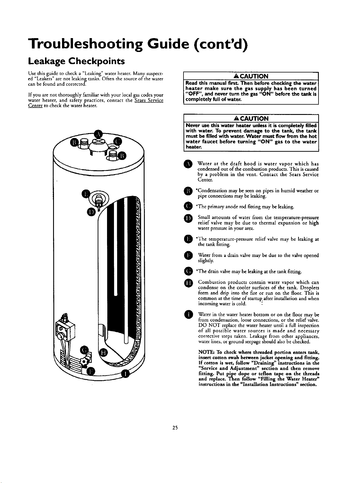
Troubleshooting Guide (cont'd)
Leakage Checkpoints
Use this guide to check a "Leaking" water heater. Many suspect-
ed "Leakers" are not leaking tanks. Often the source of the water
can be found and corrected.
If you are not thoroughly familiar with your local gas codes your
water heater, and safety practices, contact the Sears Service
Center to check the water heater.
A CAUTION ]
Read this manual E_ checking the water|
heater make sure the gas supply has been turnedJ
"OFF", and never turn the gas "ON" before the tank isJ
completely full of water. ]
I
A CAUTION I
Never use this water heater unless it iscompletely filled I
with water. To prevent damage to the tank, the tank I
must be filled with water. Water must flow from the hot I
water faucet before turning "ON" gas to the water
heater.
Water the draft hood is which has
at water
vapor
condensed out of the combustion products. This is caused
by a problem in the vent. Contact the Sears Service
Center.
Q *Condensation may seen on pipes or
be in humid weather
pipe connections may be leaking.
O'The primary anode rod fitting may be leaking.
Small amounts of water from the temperature-pressure
relief valve may be due to thermal expansion or high
waterpressureinyour area.
O'The temperature-pressure may leaking at
relief valve be
the tank fitting.
Water from drain valve be due the valve
a
may
to
opened
slightly.
O'The drain valve may be leaking at the tank fitting.
Combustion products contain water which can
vapor
condense on the cooler surfaces of the tank. Droplets
form and drip into the fire or run on the floor. This is
common at the time of startup: after installation and when
incoming water is cold.
Water in the heater bottom the floor
bewater
or on
may
from condensation, loose connections, or the relief valve.
DO NOT replace the water heater until a full inspection
of all possible water sources is made and necessary
corrective steps taken. Leakage from other appliances,
water lines, or ground seepage should also be checked.
NOTE: To check where threaded portion enters tank,
insert cotton swab between jacket opening and fitting.
If cotton is wet, follow "Draining" instructions in the
"Service and Adjustment" section and then remove
fitting. Put pipe dope or teflon tape on the threads
and replace. Then follow "Filling the Water Heater"
instructions in the Installation Instructions section.
25
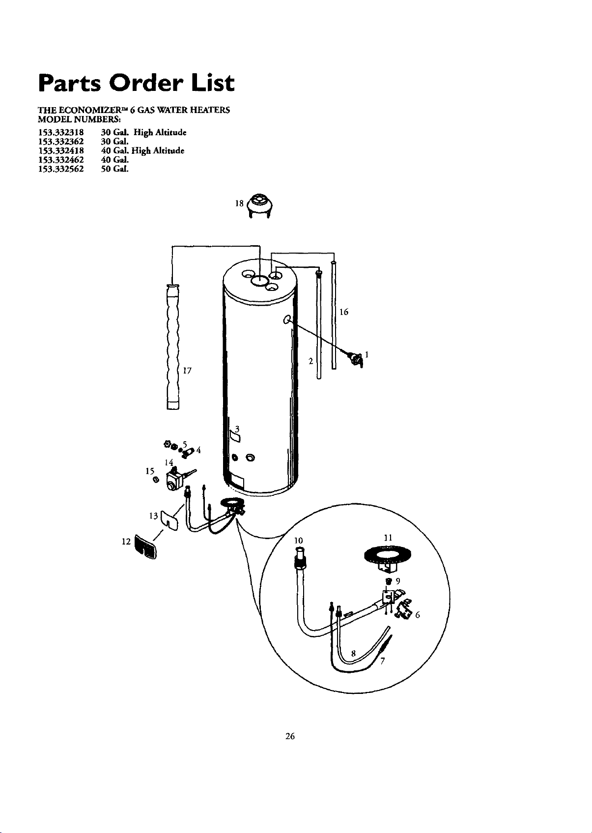
Parts Order List
THE ECONOMIZER TM 6 GAS WATER HEATERS
MODEL NUMBERS:
153.332318 30 Gal. High Altitude
153.332362 30 Gal.
153.332418 40 Gal. High Altitude
153.332462 40 Gal.
153.332562 50 Gal.
15
13
17
16
10 11
26
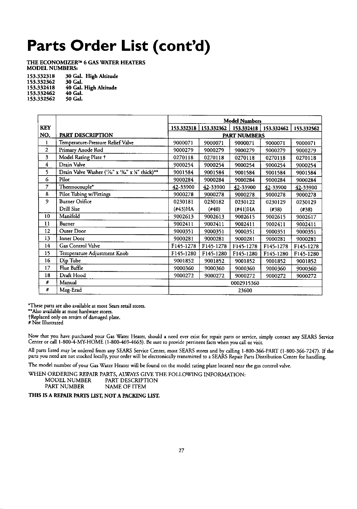
Parts Order List (cont'd)
THE ECONOMIZER TM 6 GAS WATER HEATERS
MODEL NUMBERS:
153.332318 30Gal. High Alfitude
153.332362 30G_.
153.332418 40G_.HighAlfitude
153.332462 40GM.
153.332562 50GM.
KEY
NO.
1
2
3
4
5
6
7
8
9
10
11
12
13
14
15
16
17
18
#
#
PART DESCRIPTION
Temperature-Pressure Relief Valve
Primary Anode Rod
Model Ratin[_Plate t
Drain Valve
Drain Valve Washer ('V3/'x _Y."x 7d' thick)**
Pilot
Thermocouple*
Pilot Tubing w/Fittinss
Burner Orifice
Drill Size
Manifold
Burner
Outer Door
Inner Door
Gas Control Valve
Temperature Adjustment Knob
Dip Tube
Flue Baffle
Draft Hood
Manual
Mag-Erad
Model Numbers
153.332318 153.332362 153.332418 153.332462 153.332562
PART NUMBERS
9000071
9000279
0270118
9000254
9001584
9000284
42-33900
9000278
0230181
(#43)HA
9002613
9002411
90O0351
9000281
F145-1278
F145-1280
9001852
9OOO360
9000272
9000071
9000279
0270118
9000254
9OO1584
9000284
42-33900
9000278
0230182
(#40)
9002613
9002411
9000351
9000281
F145-1278
F145-1280
9001852
9000360
9000272
9000071 9000071
9000279 9000279
0270118 0270118
9000254 9000254
9001584 9001584
9000284 9000284
42-33900 42-33900
9000278 9000278
0230122 0230129
(#41)HA (#38)
9002615 9002615
9002411 9002411
9000351 9000351
9000281 9000281
F145-1278 F145-1278
F145-1280 F145-1280
9001852 9001852
9000360 9000360
9000272 9000272
0002915360
23600
9000071
9000279
0270118
9000254
9001584
9000284
42-33900
9000278
0230129
(#38)
9002617
90O2411
9000351
9000281
F145-1278
F145-1280
9001852
9000360
9000272
*These parts are also availableat most Sears retail stores.
**Alsoavailableatmost hardware stores.
yReplaced only on retdrn of damaged plate.
# Not Illustrated
Now that you have purchased your Gas Water Heater, should a need ever exist for repair parts or service, simply contact any SEARS Service
Center or call 1-800-4-MY-HOME (1-800-469-4663). Be sure to provide pertinent facts when you call or visit.
All parts listed may be ordered from any SEARS Service Center, most SEARS stores and by calling 1-800-366-PART (1-800-366-7247). If the
parts you need arenot stocked locally, your orderwill be electronically transmitted to a SEARS Repair Parts Distribution Center for handling.
The model number of your Gas Water Heater will be found on the model rating plate located near the gas control valve.
WHEN ORDERING REPAIR PARTS, ALWAYS GIVE THE FOLLOWING INFORMATION:
MODEL NUMBER PART DESCRIPTION
PART NUMBER NAME OF ITEM
THIS IS A REPAIR PARTS LIST, NOT A PACKING LIST.
27
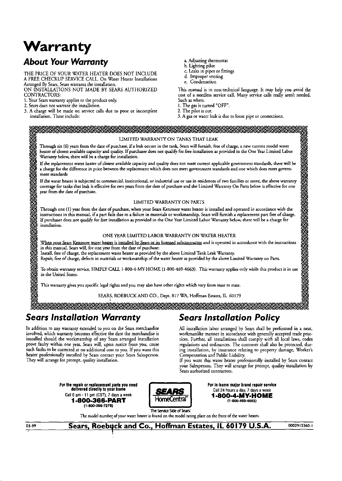
Warranty
About Your Warranty
THE PRICE OF YOUR WATER HEATER DOES NOT INCLUDE
A FREE CHECKUP SERVICE CALL. On Water Heater Installations
Arranged BySears,Sears warrants the installation.
ON INSTALLATIONS NOT MADE BY SEARS AUTHORIZED
CONTRACTORS:
1. YourSearswarranty appl!esto the product onl)_
2. Searsdoes not warrant the installation.
3. A charge will be made on service calls due to poor or incomplete
installation. These include:
a. Adjusting thermostat
h. Lightingpilot
c.Leaks in pipesorfittings
d. Improper venting
e. Condensation
This manual is in non-technical language. It may help you avoidthe
cost of a needless servicecall. Many servicecalls really aren't needed.
Such aswhen:
1.The gasis turned "OFF".
2. The pilot is out.
3. Agas orwater leak isdue to loosepipe orconnections.
LIMITED WARRANTY ON TANKS THAT LEAK
Through six (6) years from the date of purchase, ira leak occurs in the tank, Sears will filrnish, free of charge, a new current model water
heater of dosest available capacity and quality. If purchaser does not qualify for free installation as provided in the One Year Limited Labor
Warranty below, there will be a charge for installation.
lftbe replacement water heater of closest available capacity and quality does not meet current applicable government standards, there will be
a charge for the difference in price between the replacement which does not meet government standards and one which does meet govern-
ment standards
If the water heater is subjected to commercial, institutional, or industrial use or use in residences of two families or more, the above warranty
coverage for tanks that leak is effective for two years from the date of purchase and the Limited Warranty On Parts below is effective for one
year from the date of purchase.
LIMITED WARRANTY ON PARTS
Through one (1) year from the date of purchase, when your Sears Kenmore water heater is installed and operated in accordance with the
instructions in this manual, if a part fails due to a failure in materials or workmanship, Sears will furnish a replacement part free of charge.
If purchaser does not qualify for flee installation as provided in the One Year Limited Labor Warranty below, there will be a charge for
installation.
ONE YEAR LIMITED LABOR WARRANTY ON WATER HEATER
When vour Sears Kenmore water heater is installed bv Sears or its licensed subcontractor and is operated in accordance with the instructions
in this manual, Sears will, for one year from the date of purchase:
Install, free of charge, the replacement water heater as provided by the above Limited Tank Leak Warranty.
Repair, free of charge, defecrs in materials or workmanship of the water heater as provided by the above Limited Warranty on Parts.
To obtain warranty service, SIMPLY CALL 1-800-4-MY-HOME (1-800-469-4663). This warranty applies only while this product is in use
in the United States.
This warranty gives you specific legal rights and you may also have other rights which vary from state to state.
SEARS, ROEBUCK AND CO., Dept. 817 WA, Hoffman Estates, IL 60179
Sears Installation Warranty
In additionto any warranty extended to you on the Searsmerchandise
involved, which warranty becomes effectivethe date the merchandise is
installed should the workmanship of any Sears arranged installation
prove faulty within one year, Sears will, upon notice from you, cause
such faults to becorrected at no additional cost to you. If you want this
heater professionally installed by Sears contact your Sears Salesperson.
They will arrangefor prompt, quality installation.
Sears Installation Policy
All installation labor arranged by Sears shall be performed in a neat,
workmanlike manner in accordance with generally accepted trade prac-
tices, Further, all installations shall comply with all local laws, codes
regulations and ordinances.The customer shall also be protected, dur-
ing installation, by insurance relating to property damage, Worker's
Compensation and Public Liability.
If you want this water heater professionally installed by Sears contact
yourSalesperson. They will arrange for prompt, quality installation by
Sears authorized contractors.
delivereddirectlytoyourhome Call24hoursaday,7daysaweek
Cull6 am- 11 pm(CST),7 daysaweek t -800-4-MY-NON E
1-800-366-PART 1" It-OOO4e_3l
(1.8oo-3B6.727e)
The5erv_ 51deof 5ea_
The model number of your water heater is found on the model rating plate on the front of the water heater.
0s,, Sears, RoebUck and Co., HotTman Estates, IL 60179 U.S.A. ozg,s360.,