Loading ...
Loading ...
Loading ...
Installation Instructions.
Mounting System Installation
Picka location underthe sink to mount the sgstem. Location should be
easilUaccessiblewith at least Sinches of clearance between the bottom of
the filter canister and the floor or bottom of the cabinet; any lesswill result
in difficuitg of removing filter canister, Allow enough spaceon either sideof
the sgstem for the tubing connections.
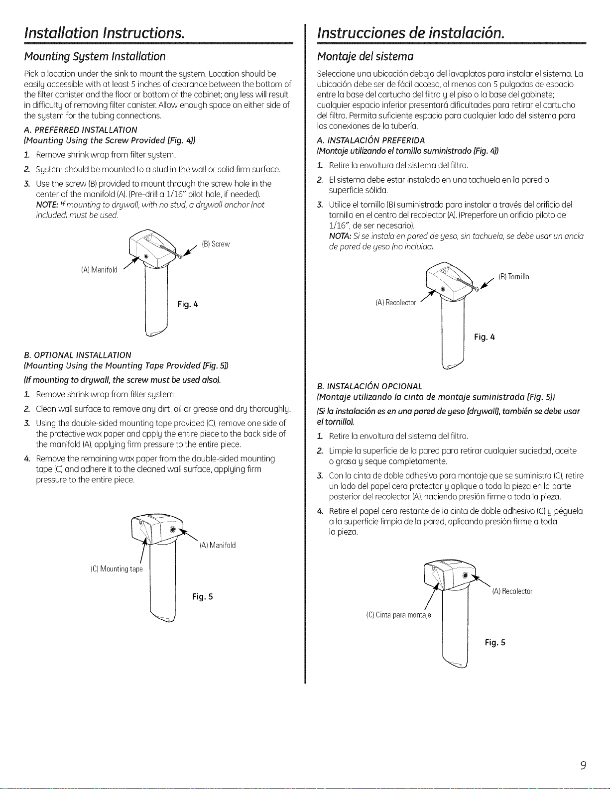
A. PREFERREDINSTALLATION
(Mounting Using the Screw Provided [Fig. 4])
1. Removeshrink wrap from filter sgstem.
2. Sgstem should be mounted to a stud inthe wall or solidfirm surface.
3. Usethe screw (B)provided to mount through the screw hole inthe
center of the manifold (A),(Pre-drilla 1/16" pilot hole, if needed),
NOTE:Ifmounting to drgwall, with nostud, adrgwall anchor (not
included)must be used.
(B)Screw
(A) Manifold
Fig. 4
B. OPTIONAL INSTALLATION
(Mounting Using the Mounting Tape Provided [Fig.S])
(Ifmounting to drywall, the screw must be used also).
1. Removeshrink wrap from filter system.
2. Cleanwall surface to remove ang dirt, oil or grease and drg thoroughlg.
3. Usingthe double-sided mounting tape provided (C),remove one sideof
the protective wax paper and apply the entire pieceto the back sideof
the manifold (A),applying firm pressureto the entire piece.
4. Removethe remaining wax paper from the double-sided mounting
tape (C)and adhere it to the cleaned wall surface,applying firm
pressureto the entire piece.
(C) Mounting tape
(A)Manifold
Fig. 5
instrucciones de instalaci6n.
Montaje del sistema
Seleccioneuna ubicaci6n debajo del lavaplatos para instalar el sistema. La
ubicaci6n debe ser def6cil acceso,al menos con Spulgadas de espacio
entre la base del cartucho del filtro gel pisoo la basedelgabinete;
cualquier espacio inferior presentar6 dificultades para retirar el cartucho
delfiltro. Permitasuficiente espacio para cualquier lado del sistema para
las conexionesde la tuberia.
A. INSTALACIONPREFERIDA
(Nontaje utilizando el tomillo suministrado [Fig.4])
Retirela envoltura del sistema del filtro.1,
z
3.
Elsistema debe estar instalado en una tachuela en la pared o
superficie s61ida.
Utiliceel tornillo (B)suministrado para instalar atrav@sdel orificio del
tornillo en el centro del recolector (A).(Preperforeun orificio piloto de
1/16", de ser necesario).
NOTA:Siseinstala en pared de9eso,sin tachuela,sedebeusar un ancla
de paredde yeso (noincluida).
(B)Tornillo
(A)Recolector
Fig. 4
B. INSTALACION OPCIONAL
(Montaje utilizando la cinta de montaje suministrada [Fig. 51)
(Sila instalaci6n es en una pared de geso [drywall], tambign se debe usar
el tornillo).
1. Retire la envoltura del sistema del filtro.
2. Limpielasuperficiede laparedpararetirarcualquiersuciedad,aceite
ograsag sequecompletamente.
3. Conlacintadedobleadhesivoparamontajequesesuministra(c),retire
unladodelpapelceraprotectorgapliqueatodala piezaenla parte
posteriordelrecolector(A),haciendopresi6nfirmeatodalapieza.
4. Retireelpapelcerarestantedelacintadedobleadhesivo(C)g p@guela
a lasuperficielimpiadela pared,aplicandopresi6nfirmea toda
lapieza.
(C) Cinta para montaje
(A)Recolector
Fig. 5
9
Loading ...
Loading ...
Loading ...