Loading ...
Loading ...
Loading ...
Installation Instructions.
Faucet Installation
Besurethere is room underneath and above the sinkto make the needed
connections. Beforestarting, make surethere issufficient room for the
batterg powered faucet base.Selectone of the following places to install
the faucet:
1. Inan existing sink sprag attachment or soap dispenser hole.
Z Ina hole to be drilled inthe sink top.
3. Ina hole to be drilled inthe countertop, next to the sink.
NOTE:Be sure the faucet base will fit fiat against the surface at the selected
location so the bottom gasket between the base and surface area willseal.
Installation Steps (refer to Fig. 2 for clarification)
1. Ifdrilling is needed, make a 3/4" diameter hole.
Be sure to use the proper procedure for drilling porcelain or stainless
steel. Special drill bits may be needed. Consult o qualified plumber for
the proper procedure.
2. Remove the faucet with pre-installed tubing, thin o-ring (D),faucet base
(E),bottom bose gasket (F),lock washer (G),hex nut (H)and mounting
bracket (I)from the packaging.
3. Feed tubing connected to the faucet through the thin o-ring (D),faucet
bose (E),bottom bose gasket (F),lockwasher (G)and hex nut (H).
4. Thread the hex nut (H)up the stem of the faucet untilthe height
between the bottom of the bose gasket (F)and top of the lock washer
(G)is slightlg larger than the thickness of the mounting surface (J).
5. Lower the faucet assemblg into place in the mounting hole and
orient to final position. Place the mounting bracket (I)above the
lock washer (G)around the faucet stem (Fig. 3),While holding the
mounting bracket in place, securelg tighten the hex nut.
NOTE:Two people mug be required to complete this step.
instrucciones de instalaci6n.
Instalaci6n del grifo
Cerci6rese de que haga suficiente espacio debajo g encima del lavaplatos
para realizar laconexi6n necesaria.Antes de empezar,cerci6rese de que
haga suficiente espacio para la base del grifo operada per bateria.
Seleccioneuno de lossiguientes lugares para instalar el grifo:
1. Enun orificio accesorio rociador existente en el lavaplatos uorificio
de dispensador dejab6n.
2. Enun orificio a perforar en la parte superior del lavaplatos.
3. Enun orificio a perforar en el mostrador, al lade del lavaplatos.
NOTA:Cerci6resede quela base delgrifo quedeplana contra la superficieen
la ubicaci6nseleccionadade manera que el empaque deabajo entre labase
geldma de la superficie quedesellado.
Pasos para la instaloci6n (consulte la Fig. 2 para aclaroci6n)
1. Si es necesario perforar, haga un orificio de 3//4"de di6metro.
Cerci6rese de utilizer el procedimiento correcto pure perforar
porcelono o ocero inoxiduble. Podr[e necesitor braces udicionoles.
Consulte a un plomero calificedo pare el procedimiento correcto.
2. Retire del paquete el grifo con la tuberia preinstalada, are t6rico fine (D),
base del grifo (E),empaque inferior de la base (F),arandela de seguridad
(G),tuerca hexagonal (H)g soporte de montaje (I).
3. Inserte latubefia conectada al grifo a troves delare t6rico fine (D),la
basedel grifo (E),el empaque inferior de la base (F),la arandela de
seguridad (G)g latuerca hexagonal (H).
4. Enrosquela tuerca hexagonal (H)en elv6stago del grifo hasta que la
altura entre laparte inferior del empaque de la base (F)g la parte
superior de laarandela de seguridad (G)sea ligeramente m6s grande
que elgrosor de la superficie de montaje (J).
5. Bajela ensambladura del grifo asu lugar en elorificio de montaje g
oriente hacia laposici6nfinal. Coloqueel soporte de montaje (I)par
encima de laarandela de seguridad (G),alrededor delv6stago delgrifo
(Fig.3).Mientras sostieneel soporte de montaje en su lugar,apriete
firmemente la tuerca hexagonal.
NOTA:Esposibfeque seannecesariasdospersonaspara completar
este paso.
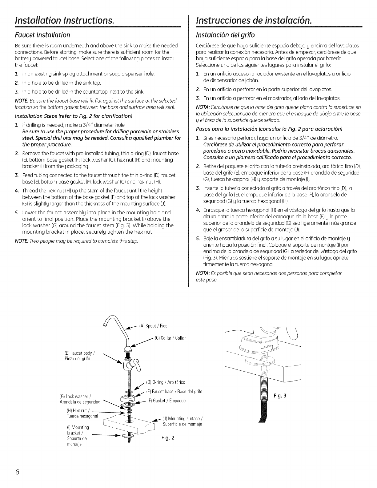
(B)Faucetbody/
Piezadel grifo
(G)Lockwasher/
ArandeladesegurJdad
(H)Hexnut/
Tuercahexagonal
(I)Mounting
bracket/
Soportede
montaje
(A)Spout/ Pica
(C)Collar/ Collar
(D)O-ring/ Aret6rico
(E)Faucetbase/ Basedel grifo
paque
(J)Mountingsurface/
Superficiedemontaje
Fig. 2
:!• ::
<::::::>
Fig. 3
8
Loading ...
Loading ...
Loading ...