Owner's Manuam
;H
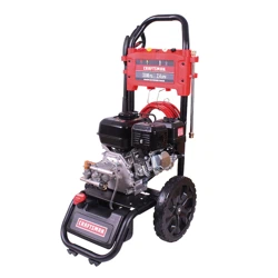
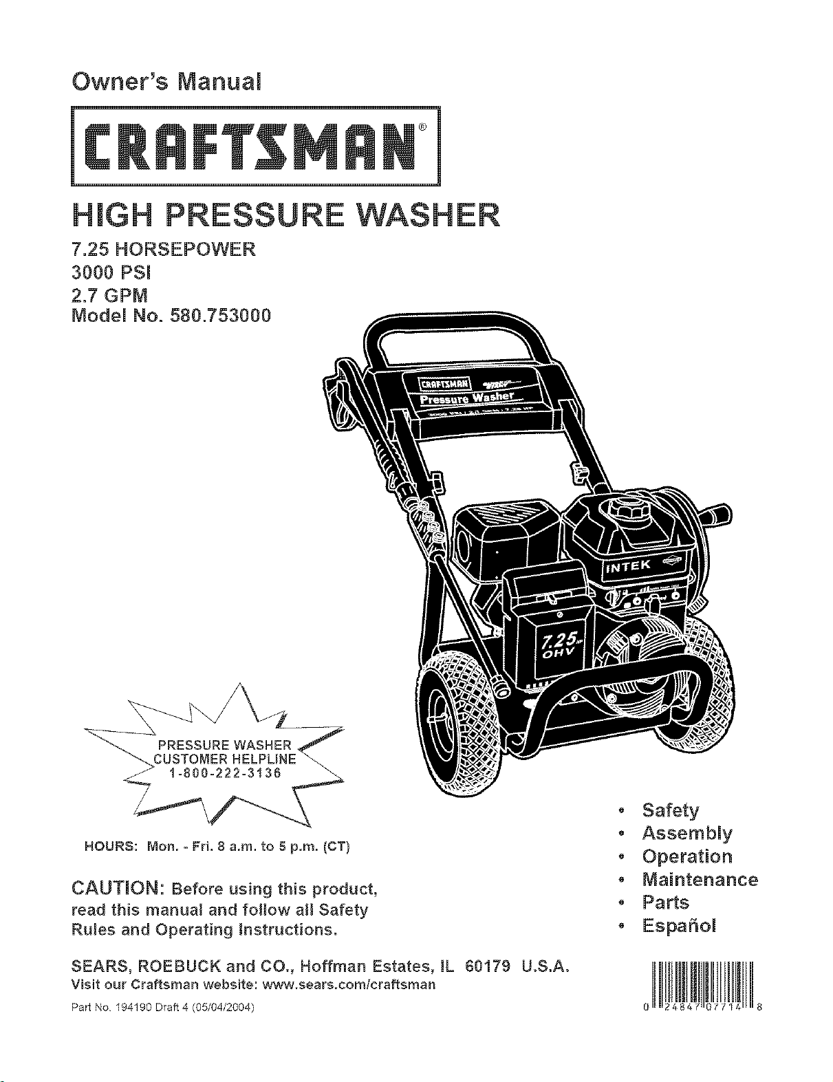
7.25 HORSEPOWER
3000 PSI
2.7 GPM
Modem No. 580.753000
HOURS: Mon.- Fri. 8 a.m. to 5 p.m. (CT)
CAUTION: Before using this product,
read this manual and fotlow ati Safety
Rules and Operating [nstructionso
SEARS, ROEBUCK and CO., Hoffman Estates, IL 60179 U.S.A.
visit our Craftsman website: www.sears.comlcraftsman
Safety
Assembmy
Operation
" Maintenance
, Parts
o EspaSol
Part No 194190 Draft 4 (05/04/2004) 9 8
WARRANTY .................................... 2
SAFETY RULES ............................... 2-4
KNOW YOUR PRESSURE WASHER ................ 5
ASSEMBLY ................................... 6-8
OPERATION ................................. 9-11
MAINTENANCE .............................. 12-15
SPECiFICATiONS ............................... 12
STORAGE .................................. 16-17
NOTES ................................... 18 & 27
TROUBLESHOOTING ............................ 19
REPLACEMENT PARTS ....................... 20-25
EMISSION CONTROL WARRANTY ................. 26
ESPAI_IOL ................................... 28-47
HOW TO ORDER PARTS ................ BACK PAGE
LIMITED WARRANTY ON CRAFTSMAN PRESSURE WASHER
For one year from the date of purchase, when this Craftsman pressure washer is maintained and operated
according to the instructions in the owner's manual, Sears will repair, free of charge, any defect in material and
workmanship.
If this washer is used for commercial purposes, this warranty applies for only 90 days from the date of
purchase. If this pressure washer is used for rental purposes, this warranty applies for only 30 days after date
of purchase.
This warranty does not cover:
• Expendable items such as spark plugs or air filters, which become worn during normal use.
• Repairs necessary because of operator abuse or negligence, including damage resulting from no water
being supplied to pump or failure to maintain the equipment according to the instructions contained in the
owner's manual.
Warranty service is available by returning the pressure washer to the nearest Sears service center or dealer in
the United States.
This warranty gives you specific legal rights and you may also have other rights, which vary from state to state.
Sears, Roebuck and Co., Dept. 817WA, Hoffman Estates, IL 60179
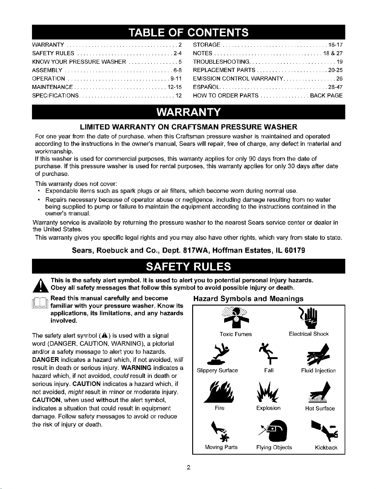
_hL This is the safety alert symbol. It is used to alert you to potential personal injury hazards.
Obey all safety messages that follow this symbol to avoid possible injury or death.
_Read this manual carefully and become
familiar with your pressure washer. Know its
applications, its limitations, and any hazards
involved.
The safety alert symbol (_) is used with a signal
word (DANGER, CAUTION, WARNING), a pictorial
and/or a safety message to alert you to hazards.
DANGER indicates a hazard which, if not avoided, will
result in death or serious injury. WARNING indicates a
hazard which, if not avoided, could result in death or
serious injury. CAUTION indicates a hazard which, if
not avoided, might result in minor or moderate injury.
CAUTION, when used without the alert symbol,
indicates a situation that could result in equipment
damage. Follow safety messages to avoid or reduce
the risk of injury or death.
Hazard Symbols and Meanings
Toxic Fumes Electrical Shock
Slippery Surface Fall Fluid Injection
Fire Explosion Hot Surface
Moving Parts Flying Objects Kickback
2
tn the State of California a spark arrestor is required
_y law (section 4442 0f the california Public
Resources Code). Other states may have similar laws.
Federal laws apply on federal lands If you equip the
muffler wit h a spark arresteri it must be maintained in
_=ffec-tiveworking order.You can order a spark arrestor
through your authorized Sears service den!or. ............
WARNING I
The engine exhaust from this product contains I
chemicals known to the State of California to cause
cancer, b rth defects, or other reproduct ve harm.
DANGER
operate pressure washer ONLY Outdoors.
,Use a respirator o_ mask whenever there is a chance
that vapors may be inha!ed
Read all instructions packed with mask so you are certain
mask wiJ!provide necessary protection against inhaling
harmful vapors.
WARNING
WHEN ADD!NG FUEL
,Turn pressure washer OFF and !et it coo! at least
2 rninutes before removing gas cap.
, Fill fuel tank Outd0Ors.
,DO NOT overfill tank. A!!ow sPaCe for fuel expansion.
, Keep fuel away from sparksi open flamesi pilot lightsi
heat; a_ other ignition sources;
, DO NOT light a cigarette 0r smoke.
WHEN OPERATING EQU!PMENT
, DO NOT tip engine or equipment at ang!e which causes
fuel to sPill
, DO NOT spray flammable liquids.
WHEN TRANSPORTING OR REPAIRING EQUIPMENT
,TransPort/repair with fuel tank EMPTY or with fue! shutoff
valve OFF.
WHEN STORING FUEL OR EQUIPMENT WITH FUEL tN
TANK
,Store away from furnaces; stoves; water heaters, clothes
d_ers or other appliances that have pilot light or Other
ignition source because they can ignite fuel vapors
WARNING
, Keep spray nozzle between 8 to 24 inches away from
c!eening surface.
, Operate this unit on a Stable Surface
, Cleaning area should have adequate slopes and
drainage _0reduce P0ssibi!_ 0f fa!lS due t0 SliPpery
surfaces.
, Be extremely carefu! !fyou must use pressure washer
from a iadderi SCaffolding Or any Other relatively unstable
location
, Firmly grasp spray gun with both hands when using high
pressure Spray to avoid injury if gun kicks back.
WARNING
WARNING
'Allow equipmen t to coo Ibeforetouching
3
WARNING
WARNING
in vicinity of equipment inuse.
CAUTION
CAUTION
' DO NOT secure sprayg un in open position
,DO NOT ]eave spray gun unattended while machine is
running •
, NEVER use a spray gun which does not have a trigger
!ock 0r trigger guard in p!ace and in working order.
,Always be certain spray gun, nozzles and accessories
are correct!y attached.
CAUTION
CAUTION
.. DO NOT Operate pressure washer above rated pressure:
, !f you have questi0ns abo_ intended use, ask dealer or
contact sears.
,NEVER operate units with broken or missing parts;or
without protective housing or covers.
,DO NOT by_ass any Safety device on this
,Before starting pressure washer in ceJdweather; check
a!I parts 0f _he equipment to be sure ice has not formed
there.
,NEVER move machine by pulling on high pressure hose.
USe handle Provided on unit.
, Check fueJ system for leaks or signs of deterioration,
such as chafed or spongy hosei loose or missing
ClamPS;Or damaged tank or cap cerrect a!l defects
bef0re operating pressure washer.
, This equipment is designed to be used with Sears
authorized parts ONLY. !f equipment is USed _ith parts
that DO NOT comply With minimum specificationsi user
assumes aJ!risks and !labilities
4
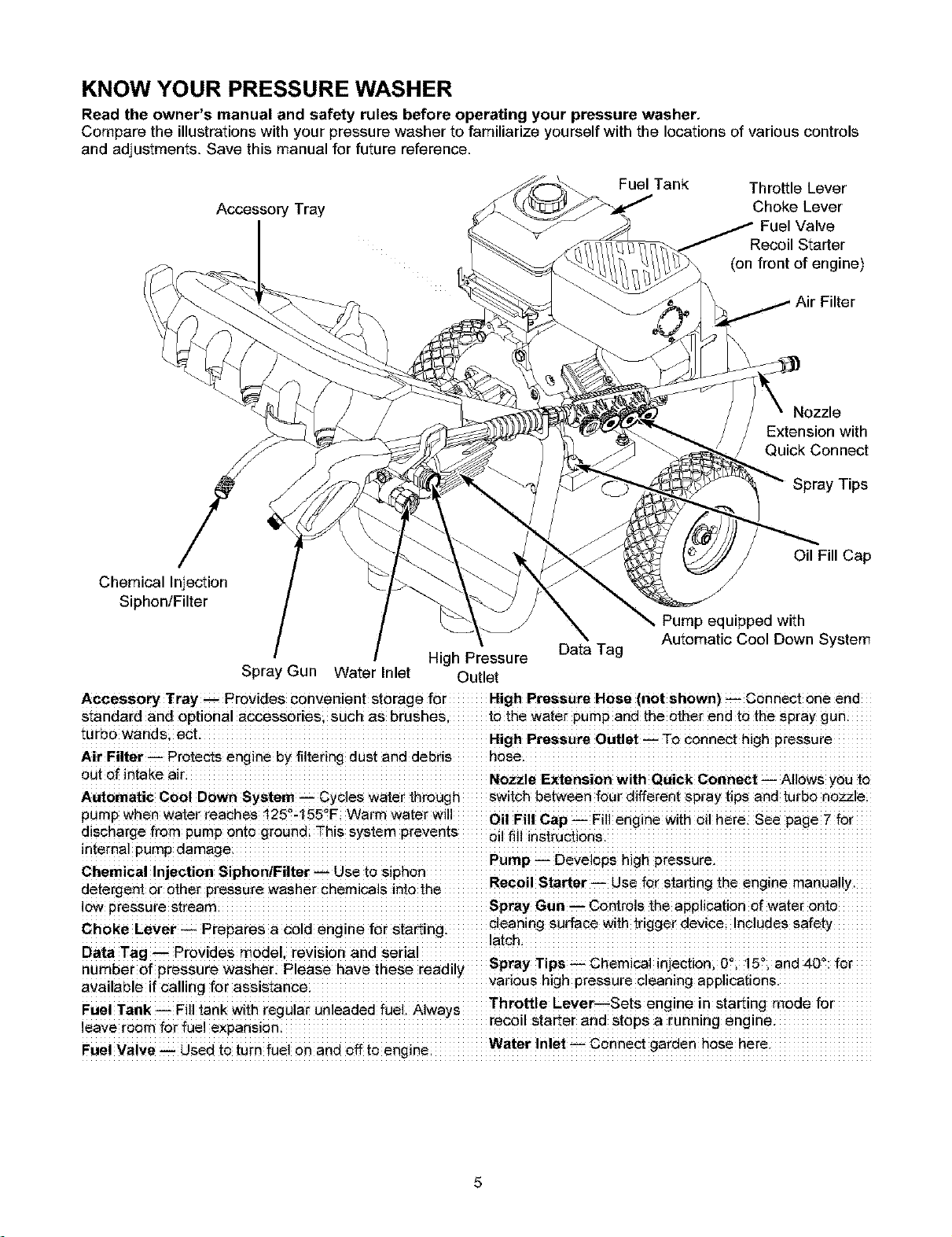
KNOW YOUR PRESSURE WASHER
Read the owner's manual and safety rules before operating your pressure washer.
Compare the illustrationswith your pressure washer to familiarize yourself with the locations of various controls
and adjustments. Save this manual for future reference.
Accessory Tray
Fuel Tank Throttle Lever
Choke Lever
Recoil Starter
(on front of engine)
Filter
Nozzle
Extension with
Quick Connect
Spray Tips
Oil Fill Cap
Chemical Injection
Siphon/Filter
High Pressure
Spray Gun Water Inlet Outlet
Data Tag
Pump equipped with
Automatic Cool Down System
ACCesSOry Tray_ PrOvides convenient storage for High Pressure Hose (n0t Sh0wn) _ €0nn_t one end
standard and optional accessoriesisuch as tothe water purnpand the ether end to the spray gun
tUrb0 wandsi eCt High Pressure outlet _ To connect high
Air Filtar. Protects engine by filtering dust and debris hose.
_Ut0f intake air Nozzle Extension With Quick C0nneCt _ AIIo_S you to
Automatic Cool Down System _ Cycles water through switch between fou_ different spray tips and turbo no_le
pump when water reaches 125%155"F, Warm water will ........ Oil Fill Cap _FiH engine wffh oil here: See page7 for
discharge from pump onto grOUnd This System prevents oil fill
ntemalpumpdamage
Pump -- Deve ops h gh pressure.
Chemica! injection @iphon!FUter _Use t_ SiPh0n ;.
Recoil Starter Use for starting the engine manually
detergent 0r 0_er pressure washer Chemicals int0 the
10wpressure stream Spray Gun---controls the applicationof water onto
clean=ngsurface w=ththgger dewce Includes safety
Ch°ke Lever _ Prepares a _old engine
Data Tag _ Provides model, revision and serial _
Spray Tips-- Chemical injectioni 0 ,15 i and 40
number of pressure washer_ Please have these readdy . . . .
V "1 ' I' f r ' vanous h_ghpressure cleaning apphcatlons
a a ablelfcallng e assistance ......................................................................................................................
i Li T__,. _.ill_.L_,.i i_.,.L.... i..i , ..;L...,.._,_ ..i _1 ... _. Throttle Lever--sets engine in starting mode
ie verboml_ _.faei x an ion.............................................. recod starterand stopsarunnmg engine ......................
a i i i i e P s
FuelValve _ Used to turn fuel on and off Water ]n!et _ Connect garden hose here.
5
Yourpressurewasherrequiressomeassemblyandis
readyforuseonlyafterithasbeenproperlyserviced
withtherecommendedoilandfuel.
Ifyou have any problems with the assembly of
your pressure washer, please call the pressure
washer helpline at 1-800-222-3t 36.
IMPORTANT: Any attempt to run the engine before it
has been serviced with the recommended oil will result
in an engine failure.
REMOVE PRESSURE WASHER
FROM CARTON
1,
2,
3.
4.
Slice two corners opposite guide handle end of
carton from top to bottom so panel can be folded
down flat.
Remove fillers, accesories and parts bag shipped
with your pressure washer.
Roll _ressure washer out open end of carton.
Check carton for additional loose parts.
CARTON CONTENTS
Check all contents. If any parts are missing or
damaged, call the pressure washer helpline at
1-800-222-3136.
Main Unit
Handle
Plastic Accessory Tray
High Pressure Hose
Spray Gun
Hose Reel
Turbo Nozzle with Quick Connect Fitting
Nozzle Extension with Quick Connect Fitting and
Spray Tip Holder
Oil Bottle
Parts Bag (which includes the following):
Owner's Manual
Owner's Registration Card
Bag containing 4 multi-colored Quick Connect
Spray Tips
Handle Fastening Hardware Kit (which includes):
Carriage Bolt
++L_ Bolt
Plastic Knobs (2)
++J'Hook
Chemical Hose Clip
Self Tapping Screws (4)
Become familiar with each piece before assembling
the pressure washer. Check all contents against the
illustration on page 5. If any parts are missing or
damaged, call the pressure washer helpline at
1-800-222-3136.
ASSEMBLING YOUR PRESSURE
WASHER
Your Craftsman high pressure washer was mostly
assembled at the factory. However, you will need to
perform these tasks before you can operate your
pressure washer:
1. Fill out and send in registration card.
2. Attach accessory tray to handle, then attach
handle to main unit.
3. Add oil to engine crankcase.
4. Add fuel to fuel tank.
5. Connect high pressure hose to spray gun and
pump.
6. Connect water supply to pump.
7. Attach nozzle extension to spray gun.
8. Select/attach quick connect spray tip to nozzle
extension.
9. Attach hose reel according to instruction sheet
included in hose reel box.
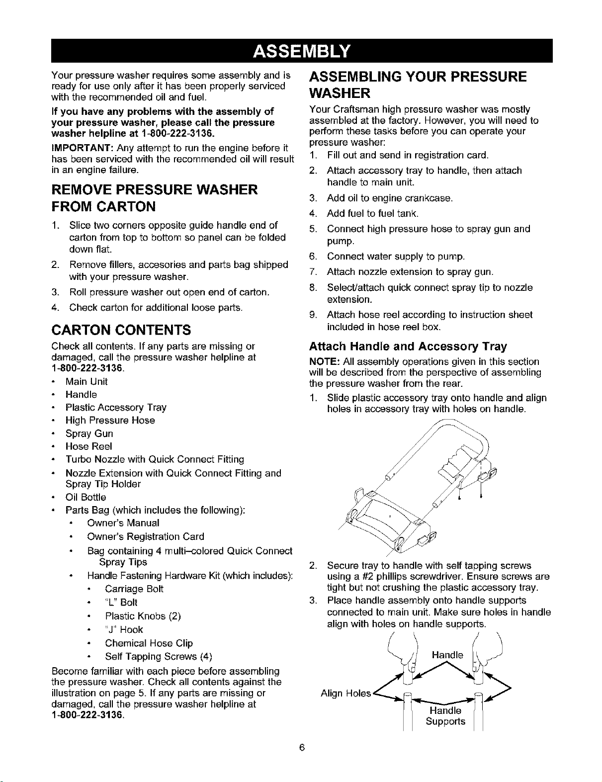
Attach Handle and Accessory Tray
NOTE: All assembly operations given in this section
will be described from the perspective of assembling
the pressure washer from the rear.
1. Slide plastic accessory tray onto handle and align
holes in accessory tray with holes on handle.
/
2. Secure tray to handle with self tapping screws
using a #2 phillips screwdriver. Ensure screws are
tight but not crushing the plastic accessory tray.
3. Place handle assembly onto handle supports
connected to main unit. Make sure holes in handle
align with holes on handle supports.
6

NOTE:Itmaybenecessarytomovethehandle
supportsfromsidetosideinordertoalignthehandle
soitwillslideoverthehandlesupports.
4. Insert"L"boltthroughholeonrightsideofhandle
(viewingfromhandlesideofunit)andattach
plasticknob.Tightenknobbyhand.
5. Insertcarriageboltthroughleftsideholefrom
outsideofunitandattachaplasticknobfrom
insideofunit(viewingunitfromthehandleside).
Tightenbyhand.
6. Insert"J+'hook into second from left slot in
accessory tray.
7. Pinch chemical hose and slide it into metal clip as
shown.
.
Tilt unit up by handle and attach metal clip to rib
on center underside of accessory tray. Slide
chemical hose through metal clip so that it is tight
but not kinked.
Add Engine Oil
IMPORTANT: Any attempt to crank or start the engine
before it has been properly serviced with the
recommended oil may result in an engine failure.
NOTE: When adding oil to the engine crankcase, use
only high quality detergent oil rated with API service
classification SF, SG, SH, SJ or higher rated SAE 30
weight. DO NOT use special additives.
1. Choose a viscosity according to table below.
p _20 _ _0 32 4o _0 _0 lOO
0 1 , , ,C +_ +2 tJ t_ lg 2g 3g _g
STARTING TEMPERATURE RANGE ANTICTPATED BEFORE NEXT OIL CNANGE
* The use of multi-viscosity oils (5W-30, 10W-30, etc.)
in temperatures above 40°F (4_C) will result in higher
than normal oil consumption. When using a multi-
viscosity oil, check oil more frequently.
** If using SAE 30 oil in temperatures below 40_F
(4_C), it will result in hard starting and possible
engine bore damage due to inadequate lubrication.
2. Place pressure washer on a level surface.
3. Clean area around oil fill.
4. Remove oil fill cap.
5. Pour oil slowly. Fill to the point of overflowing.
6. Replace oil fill cap, tighten securely.
NOTE: Check oil often during engine break-in.
Add Fuel
,_ WARNINGf NEVER fill fuel tank indoors.
NEVER fill fuel tank when engine is running or
hot. Allow unit to cool for two minutes before
refueling. DO NOT light a cigarette or smoke
when filling the fuel tank.
,_ WARNING] NEVER fill fuel tank completely
full. Provide space for fuel expansion. Wipe
away any fuel spillage from engine and
equipment before starting.
Use fresh, clean unleaded automotive fuel and
store in approved, clean, covered containers. Use
clean fill funnels. NEVER use "stale" fuel left over
from last season or fuel stored for long periods.
Clean area around fuel fill cap, remove cap.
7
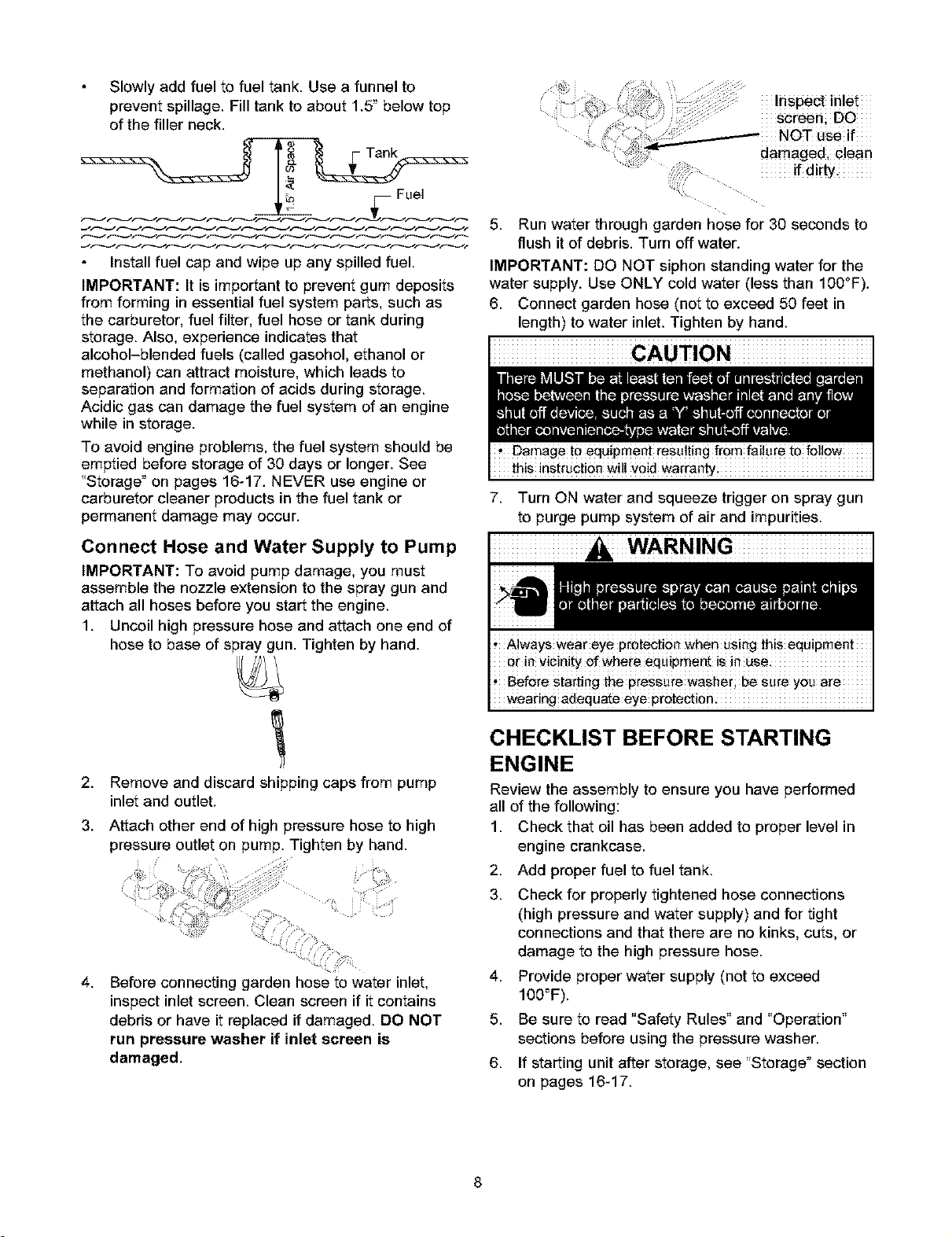
Slowlyaddfueltofueltank.Useafunnelto
preventspillage.Filltanktoabout1.5"belowtop
ofthefillerneck.
Fuel
Install fuel cap and wipe up any spilled fuel.
IMPORTANT: It is important to prevent gum deposits
from forming in essential fuel system parts, such as
the carburetor, fuel filter, fuel hose or tank during
storage. Also, experience indicates that
alcohol-blended fuels (called gasohol, ethanol or
methanol) can attract moisture, which leads to
separation and formation of acids during storage.
Acidic gas can damage the fuel system of an engine
while in storage.
To avoid engine problems, the fuel system should be
emptied before storage of 30 days or longer. See
"Storage _on pages 16-17. NEVER use engine or
carburetor cleaner products in the fuel tank or
permanent damage may occur.
Inspect inlet
J
screen; DO
, _;':_:i :_:./_ NoT use if
.- aa agea cea
if di_.
Run water through garden hose for 30 seconds to
flush it of debris. Turn off water.
Connect Hose and Water Supply to Pump
IMPORTANT: To avoid pump damage, you must
assemble the nozzle extension to the spray gun and
attach all hoses before you start the engine.
1. Uncoil high pressure hose and attach one end of
hose to base of spray gun. Tighten by hand.
IMPORTANT: DO NOT siphon standing water for the
water supply. Use ONLY cold water (less than 100°F).
6. Connect garden hose (net to exceed 50 feet in
length) to water inlet. Tighten by hand.
this instructionwill voidwarranty
7. Turn ON water and squeeze trigger on spray gun
to purge pump system of air and impurities.
2.
3.
4.
Remove and discard shipping caps from pump
inlet and outlet.
Attach other end of high pressure hose to high
pressure outlet on pump. Tighten by hand.
Before connecting garden hose to water inlet,
inspect inlet screen. Clean screen if it contains
debris or have it replaced if damaged. DO NOT
run pressure washer if inlet screen is
damaged,
wear!rig adequate eye protection:
CHECKLIST BEFORE STARTING
ENGINE
Review the assembly to ensure you have performed
all of the following:
1. Check that oil has been added to proper level in
engine crankcase.
2. Add proper fuel to fuel tank.
3. Check for properly tightened hose connections
(high pressure and water supply) and for tight
connections and that there are no kinks, cuts, or
damage to the high pressure hose.
4. Provide proper water supply (net to exceed
100=F).
5. Be sure to read "Safety Rules" and "Operation"
sections before using the pressure washer.
6. If starting unit after storage, see "Sterage" section
on pages 16-17.
8
HOW TO USE YOUR PRESSURE
WASHER
If you have any problems operating your pressure
washer, please call the pressure washer helpline at
1-800-222-3136.
To Start Your Pressure Washer
To start your engine-powered pressure washer for the
first time, follow these instructions step-by-step. This
starting information also applies whenever you start
the engine after you have let the pressure washer sit
idle for at least a day.
1. Place pressure washer near an outside water
source capable of supplying water at a flow rate
greater than 3.7 gallons per minute and no less than
20 PSI at pressure washer end of garden hose.
2.
.
4.
Check that high pressure hose is tightly connected
to spray gun and pump. See "Assembling Your
Pressure Washer" for illustrations.
Make sure unit is in a level position.
Connect garden hose to water inlet on pressure
washer pump. Turn ON water.
5. Squeeze trigger on gun to purge pump system of
air and impurities.
6. Place colored quick connect spray tips in slots on
holder that's attached to nozzle extension.
7. Attach nozzle extension to spray gun. Tighten by
hand.
8. Choose spray tip you want to use and insert it into
nozzle extension. See "How to Use Spray Tips" on
page 10.
9. Engage safety latch to spray gun trigger.
_ safety LatCh
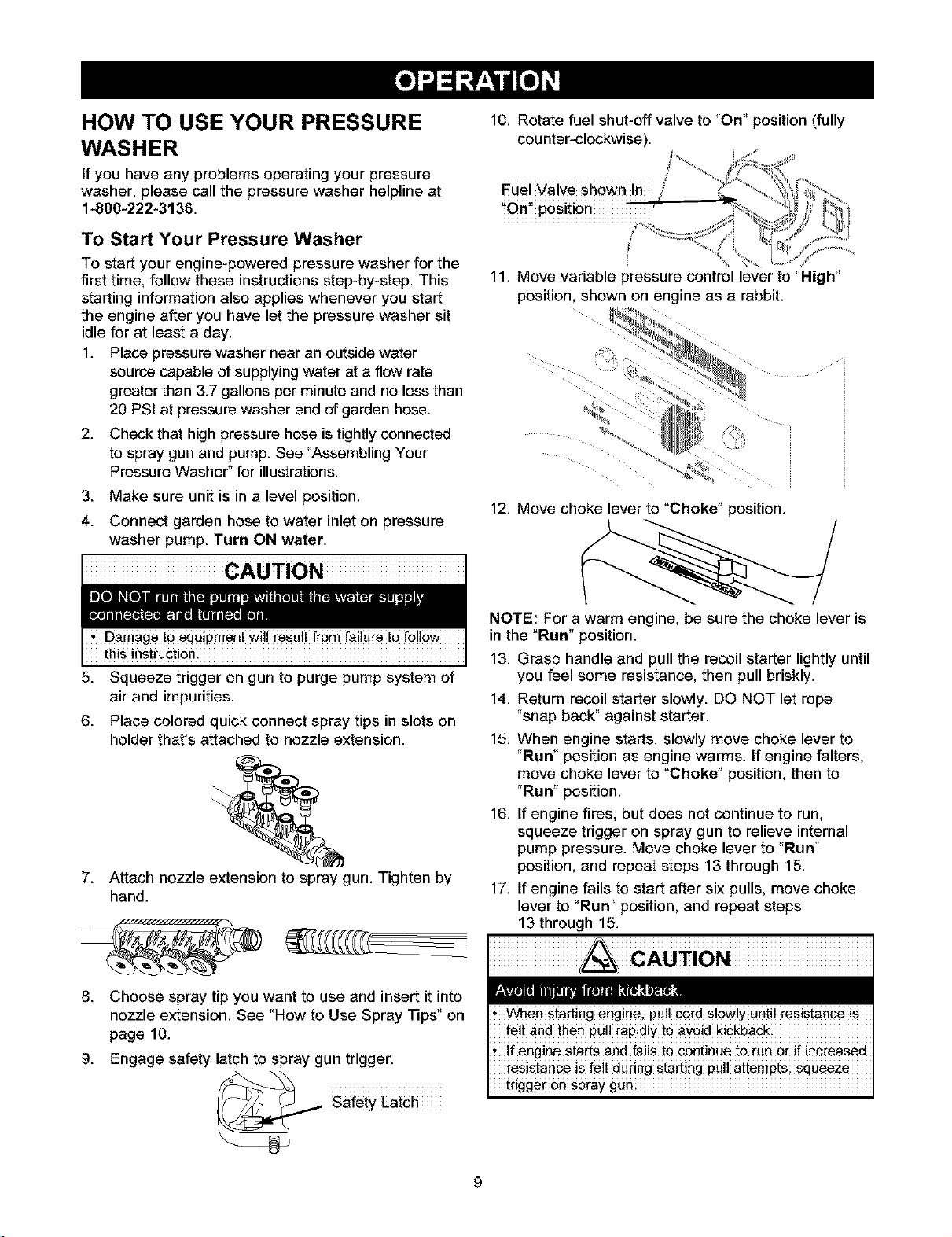
10. Rotate fuel shut-off valve to "On" position (fully
counter-clockwise).
J
Fuel Valve shewn in
"On_ pesition
11. Move variable pressure control lever to 'High"
position, shown on engine as a rabbit.
12. Move choke lever to "Choke" position.
NOTE: For a warm engine, be sure the choke lever is
in the "Run" position.
13. Grasp handle and pull the recoil starter lightly until
you feel some resistance, then pull briskly.
14. Return recoil starter slowly. DO NOT let rope
"snap back_'against starter.
15. When engine starts, slowly move choke lever to
'Run" position as engine warms. If engine falters,
move choke lever to "Choke" position, then to
'Run" position.
16. If engine fires, but does not continue to run,
squeeze trigger on spray gun to relieve internal
pump pressure. Move choke lever to "Run"
position, and repeat steps 13 through 15.
17. If engine fails to start after six pulls, move choke
lever to "Run" position, and repeat steps
13 through 15.
9
trigger 0n spray gun:
How to Stop Your Pressure Washer
Move variable pressure control lever on engine to
"Stop" position.
Squeeze trigger on the spray gun to relieve
pressure in the hose.
NOTE: A small amount of water will squirt out when
you release the pressure.
How to Use Accessory Tray
The unit isequipped with an accessory tray with places
to store your nozzle extension and turbo nozzle, and
slots to hold the cleaning solution bottle and the
detergent siphoning filter. There are also two hooks at
the ends of the handle to hold your spray gun.
1. Place nozzle extension through hole on accessory
tray as shown.
2. Hang chemical solution bottle on ++J"hook and
place detergent siphoning filter in last slot on left.
3. Place turbo nozzle in the last slot on right in tray.
4. Place spray gun on hook attached to accessory
tray on right side of unit.
How to Use Spray Tips
The quick-connect on the nozzle extension allows you
to switch between four different spray tips. The spray
tips vary the spray pattern as shown above.
latChon the _figger,
Follow these inst_ucUons to change spray tips:
1. Engage safety latch on spray gun.
2. Pull back collar on quick-connect and pull current
spray tip off. Store spray tips in holder provided on
the nozzle extension.
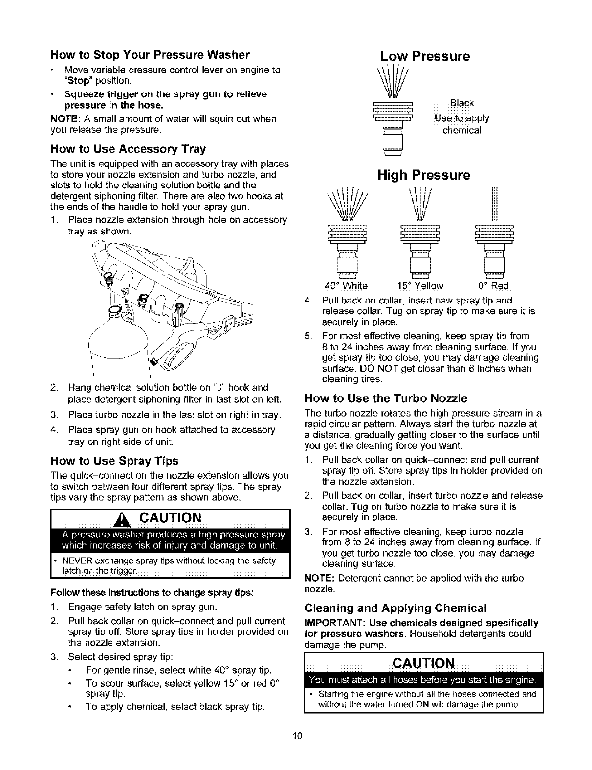
3. Select desired spray tip:
For gentle rinse, select white 40 ° spray tip.
To scour surface, select yellow 15° or red 0°
spray tip.
To apply chemical, select black spray tip.
Low Pressure
Black
Use to apply
chemical
4,
5.
40_ White
High Pressure
YY
15+Yellow 0" Red
Pull back on collar, insert new spray tip and
release collar. Tug on spray tip to make sure it is
securely in place.
For most effective cleaning, keep spray tip from
8 to 24 inches away from cleaning surface. If you
get spray tip toe close, you may damage cleaning
surface. DO NOT get closer than 6 inches when
cleaning tires.
How to Use the Turbo Nozzle
The turbo nozzle rotates the high pressure stream in a
rapid circular pattern. Always start the turbo nozzle at
a distance, gradually getting closer to the surface until
you get the cleaning force you want.
1. Pull back collar on quick-connect and pull current
spray tip off. Store spray tips in holder provided on
the nozzle extension.
2. Pull back on collar, insert turbo nozzle and release
collar. Tug on turbo nozzle to make sure it is
securely in place.
3. For most effective cleaning, keep turbo nozzle
from 8 to 24 inches away from cleaning surface. If
you get turbo nozzle too close, you may damage
cleaning surface.
NOTE: Detergent cannot be applied with the turbo
nozzle.
Cleaning and Applying Chemical
IMPORTANT: Use chemicals designed specifically
for pressure washers. Household detergents could
damage the pump.
10

To apply detergent follow these steps:
1. Review spray tip use.
2. Prepare detergent solution as required by
manufacturer.
3. Hang detergent solution on "J" hook attached to
accessory tray.
/
4. Place filter end of detergent siphoning tube into
detergent container.
5. Make sure black spray tip is installed.
NOTE: Detergent cannot be applied with the high
pressure spray tips (White, Yellow, or Red).
6. Make sure garden hose is connected to water
inlet. Check that high pressure hose is connected
to spray gun and pump and start engine.
7. Apply detergent to a dry surface, starting at lower
portion of area to be washed and work upward,
using long, even, overlapping strokes.
8.
Allow detergent to soak in between 3-5 minutes
before washing and rinsing. Reapply as needed to
prevent surface from drying. DO NOT allow
detergent to dry on (prevents streaking).
IMPORTANT: You must flush the chemical injection
system after each use by placing the filter into a
bucket of clean water, then run the pressure washer in
low pressure for 1-2 minutes.
Pressure Washer Rinsing
Wash and Rinse Surface
This pressure washer permits regulation of output
water pressure by varying the engine speed. The
variable pressure control lever found on the front of
the engine may be set as shown:
Pressure Low to High
Duty Ligh_ Medium Hea_
Application remora!
Boat Drivewey Degreasing
FUrniture Deck
After you have applied detergent, scour the
surface and rinse it clean as follows:
1. Apply safety latch to spray gun.
2. Remove black chemical nozzle from nozzle
extension.
3. Select and install desired high pressure nozzle
following instructions "How to Use Spray Tips"on
page 10.
4. Keep spray gun a safe distance from the area you
plan to spray.
WARNING
,Keep Spray n_le between 8 te2_ inches a_y from
cleaning surfac_
, Operate this unit on a Stable Surface
! Be extremely carefu! ix you must use the pressure
washer from a !adderi s#affo!dJng or any other re!ative]y
unstable 10cati0n.
, Firmly grasp spray gun with both hands when using high
pressure spray to avoid injury if gun kicks back.
5. Adjust spray pressure by sliding variable pressure
contol lever left or right, as shown on page 9.
6. Apply a high pressure spray to a small area and
then check the surface for damage. If no damage is
found, you can assume it is okay to continue rinsing.
7. Start at top of area to be rinsed, working down with
same overlapping strokes as you used for cleaning.
How to Use the Hose Reel
Your pressure washer is equipped with a hose reel
that is designed to store your hose when unit is not in
use. These instructions are for short term storage
only. For long term storage see "Storage" on page 16.
After each use:
1. Disconnect hose from spray gun and high
pressure outlet on pump.
2. Drain water from hose.
3. Slide one end of hose into hole on hose reel. Turn
hose reel with handle to coil hose onto reel.
IMPORTANT: DO NOT use your pressure washer
with the hose coiled onto the hose reel. The hose reel
is for storage purposes only.
Automatic Cool Down System
(Thermal Relief)
If you run the engine on your pressure washer for
3-5 minutes without pressing the trigger on the spray
gun, circulating water in the pump can reach
temperatures above 125_F. The system engages to
cool the pump by discharging the warm water onto
the ground.
11
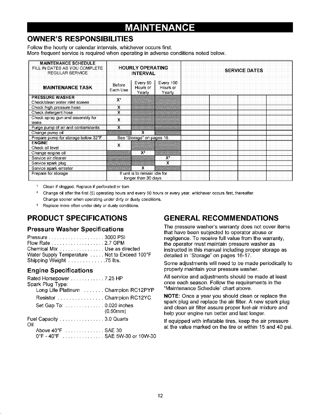
OWNER'S RESPONSIBILITIES
Follow the hourly or calendar intervals, whichever occurs first.
More frequent service is required when operating in adverse conditions noted below.
F!LL IN DATES AS YOU CQMpI-ETE HOURLy OPERAT!NG
REGULAR SERVICE INTERVAt_ I }=r_v!_=: U'_=}
MAINTENANCETASK Ho_rs0r .................................................
PRESSURE WASHER ..i_ I I I
ChecktcJean water inlet screen ^ _ I I I
Check high pressure hose IX _ I I ]
Check detergent hose I X _ I I ]
Punge pump of air and contaminants I _WWWWWW_,_ I I ]
Change pump oil _ X _ i i ]
Change engine oil _ X_ _ I I ]
Service spark attester _ x _ I I ]
P!epare f0r storage !f anit is _# _emain idle for
Clean if clogged. Replace if perforated or tom
2 Change oil after the first (5) operating hours and every 50 hours or every year, whichever occurs first, thereafter
Change sooner when operating under dirty or dusty conditions.
Replace more often under dirty or dusty conditions
PRODUCT SPECIFICATIONS
Pressure Washer Specifications
Pressure .................... 3000 PSI
Flow Rate ................... 2,7 GPM
Chemical Mix ................ Use as directed
Water Supply Temperature ..... Not to Exceed 100°F
Shipping Weight ............. 75 Ibs.
Engine Specifications
Rated Horsepower ............ 7,25 HP
Spark Plug Type:
Long Life Platinum ....... Champion RC12PYP
Resistor ................ Champion RC12YC
Set Gap To: .............. 0.020 inches
(0.50mm)
Fuel Capacity ................ 3,0 Quarts
Oil
Above 40°F .............. SAE 30
0°F - 40°F ............... SAE 5W-30 or 10W-30
GENERAL RECOMMENDATIONS
The pressure washer's warranty does not cover items
that have been subjected to operator abuse or
negligence. To receive full value from the warranty,
the operator must maintain pressure washer as
instructed in this manual including proper storage as
detailed in "Storage son pages 16-17.
Some adjustments will need to be made periodically to
properly maintain your pressure washer.
All service and adjustments should be made at least
once each season. Follow the requirements in the
"Maintenance Schedule" chart above.
NOTE: Once a year you should clean or replace the
spark plug and replace the air filter. A new spark plug
and clean air filter assure proper fuel-air mixture and
help your engine run better and last longer.
If equipped with inflatable tires, keep the air pressure
at the value marked on the tire or within 15 and 40 psi.
12
BEFORE EACH USE
1. Check engine oil level.
2. Check water inlet screen for damage.
3. Check high pressure hose for leaks.
4. Check chemical filters for damage.
5. Check spray gun and nozzle extension assembly
for leaks.
6. Purge pump of air and contaminants.
PRESSURE WASHER
MAINTENANCE
Check and Clean Inlet Screen
Examine garden hose inlet screen. Clean if it is
clogged or replace if it is torn.
Check High Pressure Hose
High pressure hoses can develop leaks from wear,
kinking, or abuse. Inspect hose before each use.
Check for cuts, leaks, abrasions, bulging of cover, or
damage or movement of couplings. If any of these
conditions exist, replace hose immediately.
Check Gun and Nozzle Extension
Examine hose connection to spray gun and make sure
it is secure. Test trigger by pressing it and making
sure it springs back into place when you release it. Put
safety latch in UP position and test trigger. You should
not be able to press trigger. Replace spray gun
immediately if it fails any of these tests.
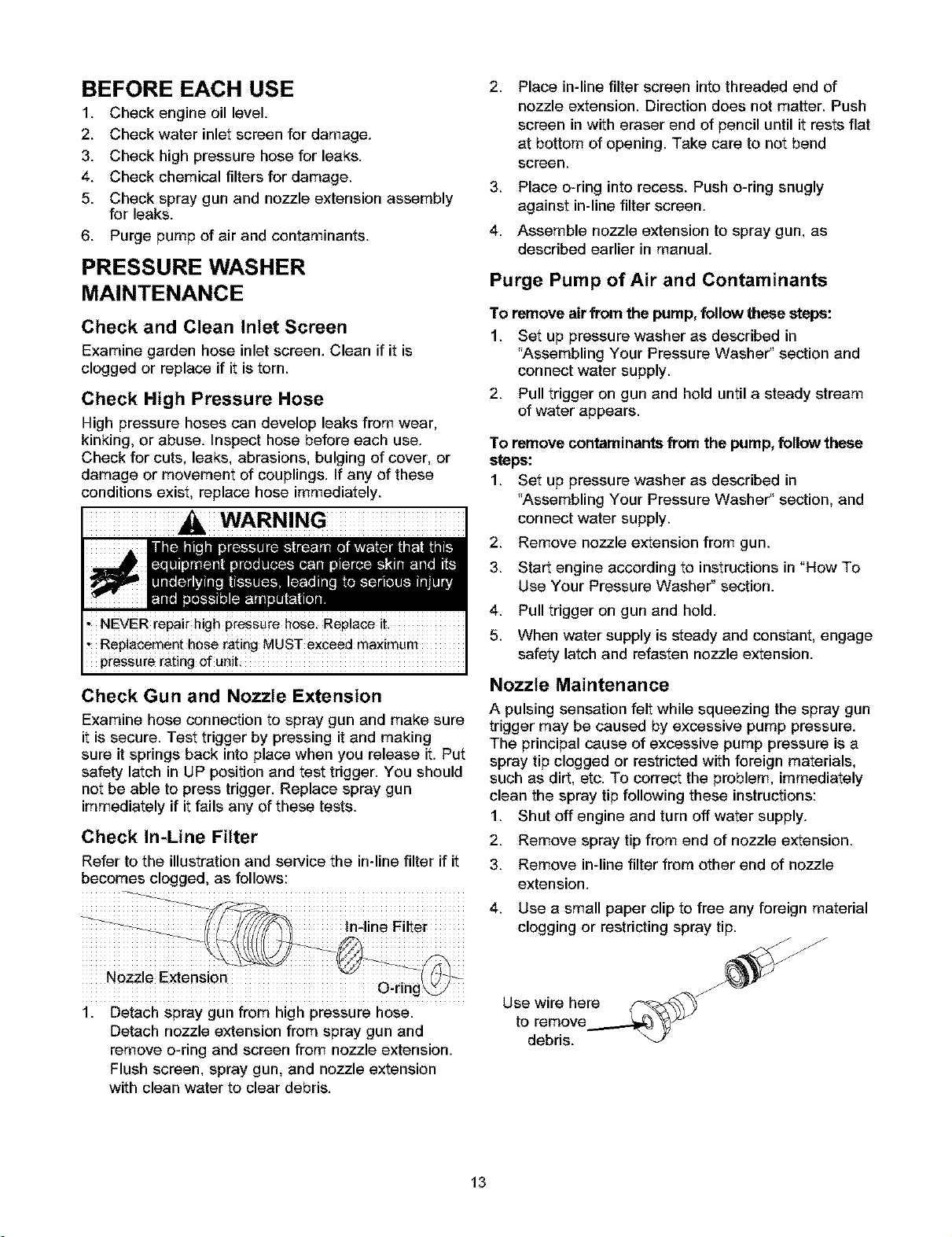
Check In-Line Filter
Refer to the illustration and service the in-line filter if it
becomes clogged, as follows:
............. _ ............ In4ine Filter ........
Nozzle Extension O tin
g
1. Detach spray gun from high pressure hose.
Detach nozzle extension from spray gun and
remove o-ring and screen from nozzle extension.
Flush screen, spray gun, and nozzle extension
with clean water to clear debris.
2. Place in-line filter screen into threaded end of
nozzle extension. Direction does not matter. Push
screen in with eraser end of pencil until it rests flat
at bottom of opening. Take care to not bend
screen.
3. Place o-ring into recess. Push o-ring snugly
against in-line filter screen.
4. Assemble nozzle extension to spray gun, as
described earlier in manual.
Purge Pump of Air and Contaminants
To remove air from the pump, follow these steps:
1. Set up pressure washer as described in
"Assembling Your Pressure Washer" section and
connect water supply.
2. Pull trigger on gun and hold until a steady stream
of water appears.
To remove contaminants from the pump, follow these
steps:
1. Set up pressure washer as described in
"Assembling Your Pressure Washer" section, and
connect water supply.
2. Remove nozzle extension from gun.
3. Start engine according to instructions in "How To
Use Your Pressure Washer s section.
4. Pull trigger on gun and hold.
5. When water supply is steady and constant, engage
safety latch and refasten nozzle extension.
Nozzle Maintenance
A pulsing sensation felt while squeezing the spray gun
trigger may be caused by excessive pump pressure.
The principal cause of excessive pump pressure is a
spray tip clogged or restricted with foreign materials,
such as dirt, etc. To correct the problem, immediately
clean the spray tip following these instructions:
Shut off engine and turn off water supply.
1.
2.
3.
4.
Remove spray tip from end of nozzle extension.
Remove in-line filter from other end of nozzle
extension.
Use a small paper clip to free any foreign material
clogging or restricting spray tip.
Use wire here
to remove
debris.
13
.
Back flush between 30 to 60 seconds. 1.
3.
6. Reinstall spray tip and in-line filter into nozzle
extension. 4.
7. Reconnect nozzle extension to spray gun. 5.
8. Reconnect water supply, turn on water, and start
engine. 6.
9. Test pressure washer by operating with each 7.
Quick Connect spray tips. 8.
Using a garden hose, remove additional debris by Change oil while engine is still warm from running, as
back flushing water through nozzle extension, follows:
Drain fuel tank by running pressure washer until
fuel tank is empty.
Disconnect spark plug wire and keep it away from
spark plug.
Remove oil drain plug and drain oil into
appropriate receptacle.
Reinstall drain plug. Remove oil fill cap.
Fill to point of overflowing at oil fill cap with
recommended oil.
Reinstall oil fill plug and tighten securely.
Wipe up any remaining oil.
Reconnect spark plug wire to spark plug.
O-Ring Maintenance
Purchase an O-Ring Repair Kit, item number
71-75116, at your local Sears or by calling
1-800-366-PART or online at www.sears.com. It is not
included with the pressure washer. This kit includes
replacement o-rings, rubber washer and water inlet
filter. Refer to the instruction sheet provided in the kit
to service your unit's o-rings.
PUMP MAINTENANCE
This model does not require any pump maintenance.
The pump is pre-lubricated and sealed, requiring no
additional lubrication for the life of the pump.
Service Air Cleaner
Your engine will not run properly and may be
damaged if you run it with a dirty air cleaner.
Service the air cleaner once every 100 hours of
operation or once each year, whichever comes first.
Service more often if operating under dirty or dusty
conditions. Replacements are available at your local
Sears service center.
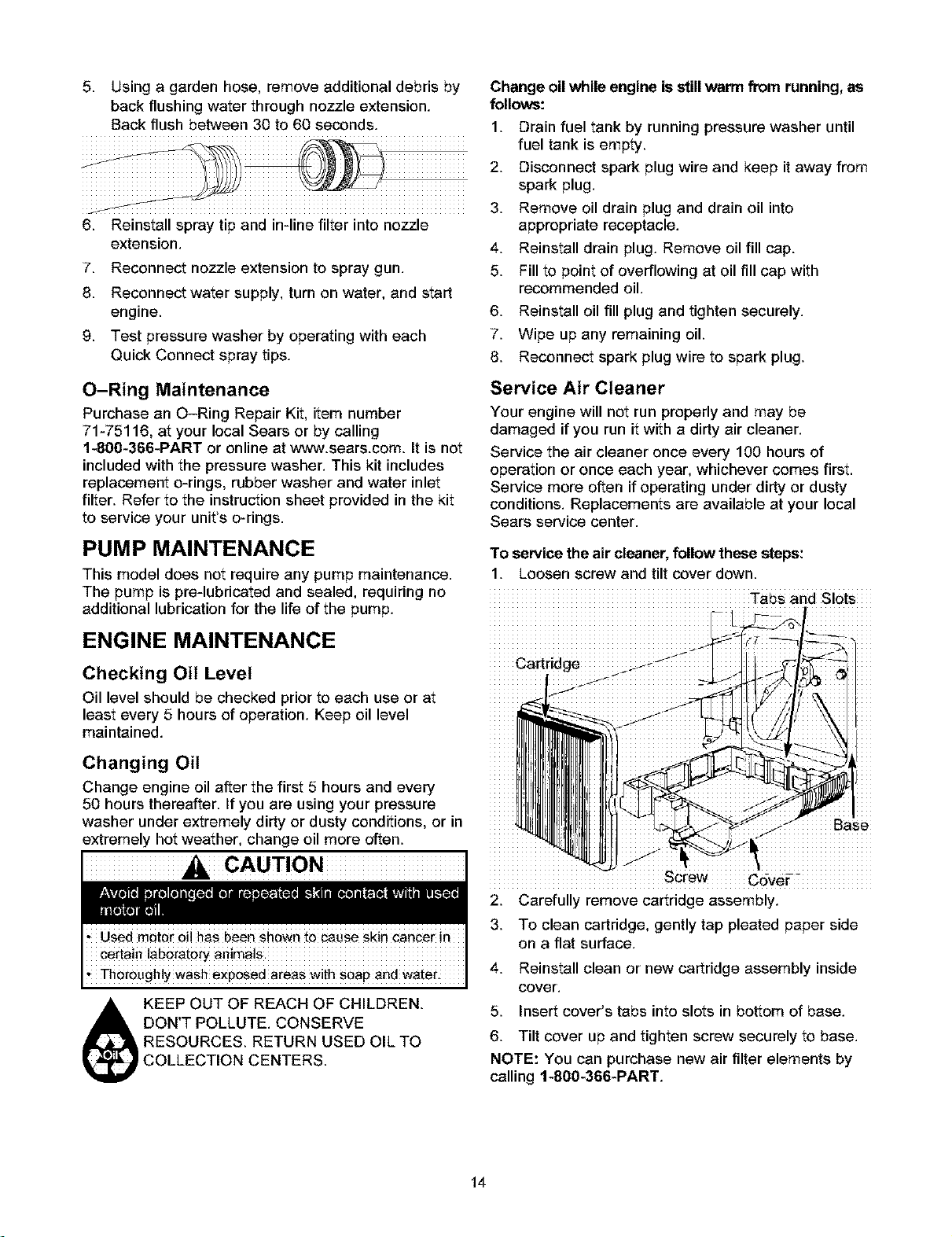
To service the air cleaner, follow these steps:
1. Loosen screw and tilt cover down.
Tabs and Slots
ENGINE MAINTENANCE
Checking Oil Level
Oil level should be checked prior to each use or at
least every 5 hours of operation. Keep oil level
maintained.
Changing Oil
Change engine oil after the first 5 hours and every
50 hours thereafter. If you are using your pressure
washer under extremely dirty or dusty conditions, or in
extremely hot weather, change oil more often.
CAUTION
/ Base
screw Cdver-_ ................
2. Carefully remove cartridge assembly.
3. To clean cartridge, gently tap pleated paper side
on a flat surface.
KEEP OUT OF REACH OF CHILDREN.
DON'T POLLUTE. CONSERVE
RESOURCES. RETURN USED OIL TO
COLLECTION CENTERS.
4. Reinstall clean or new cartridge assembly inside
cover.
5. Insert cover's tabs into slots in bottom of base.
6. Tilt cover up and tighten screw securely to base.
NOTE: You can purchase new air filter elements by
calling 1-800-366-PART.
14
Service Spark Plug
Service the spark plug every 100 hours of operation or
yearly, whichever occurs first.
WARNING
1. Clean area around spark plug.
2. Remove and inspect spark plug.
3. Replace spark plug if electrodes are worn, or if
insulator is cracked or chipped.
4. For replacement use either the standard resistor
spark plug, Champion RC12YC or the long life
platinum spark plug, Champion RC12PYP.
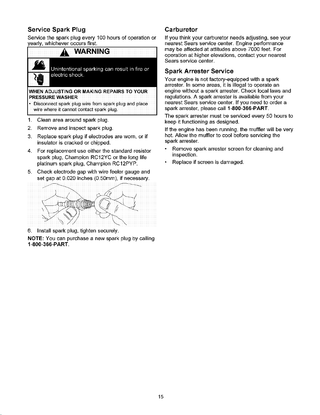
5. Check electrode gap with wire feeler gauge and
set gap at 0.020 inches (0.50ram), if necessary.
Carburetor
If you think your carburetor needs adjusting, see your
nearest Sears service center. Engine performance
may be affected at attitudes above 7000 feet. For
operation at higher elevations, contact your nearest
Sears service center.
Spark Arrester Service
Your engine is not factory-equipped with a spark
arrester. In some areas, it is illegal to operate an
engine without a spark arrester. Check local laws and
regulations. A spark arrester is available from your
nearest Sears service center. If you need to order a
spark attester, please call 1-800-366-PART.
The spark arrester must be serviced every 50 hours to
keep it functioning as designed.
If the engine has been running, the muffler will be very
hot. Allow the muffler to cool before servicing the
spark attester.
Remove spark arrester screen for cleaning and
inspection.
Replace if screen is damaged.
6. Install spark plug, tighten securely.
NOTE: You can purchase a new spark plug by calling
1-800-366-PART.
15
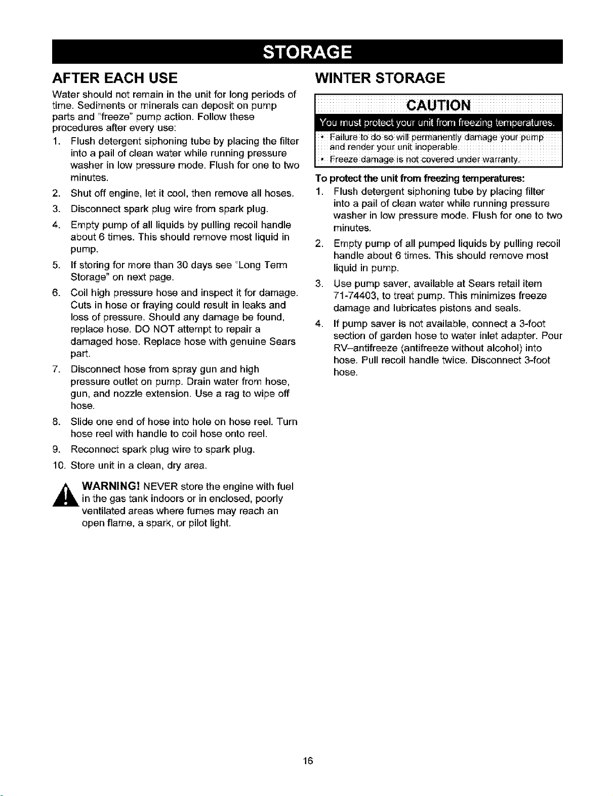
AFTER EACH USE
Water should not remain in the unit for long periods of
time. Sediments or minerals can deposit on pump
parts and "freeze" pump action. Follow these
procedures after every use:
1. Flush detergent siphoning tube by placing the filter
into a pail of clean water while running pressure
washer in low pressure mode. Flush for one to two
minutes.
2. Shut off engine, let it cool, then remove all hoses.
3. Disconnect spark plug wire from spark plug.
4. Empty pump of all liquids by pulling recoil handle
about 6 times. This should remove most liquid in
pump.
5. If storing for more than 30 days see "Long Term
Storage" on next page.
6. Coil high pressure hose and inspect it for damage.
Cuts in hose or fraying could result in leaks and
loss of pressure. Should any damage be found,
replace hose. DO NOT attempt to repair a
damaged hose. Replace hose with genuine Sears
part.
7. Disconnect hose from spray gun and high
pressure outlet on pump. Drain water from hose,
gun, and nozzle extension. Use a rag to wipe off
hose.
8. Slide one end of hose into hole on hose reel. Turn
hose reel with handle to coil hose onto reel.
9. Reconnect spark plug wire to spark plug.
10. Store unit in a clean, dry area.
_ WARNING] NEVER store the engine with fuel
in the gas tank indoors or in enclosed, poorly
ventilated areas where fumes may reach an
open flame, a spark, or pilot light.
WINTER STORAGE
Freeze damage is not covered under warranty
To protect the unitfrom freezing temperatures:
1. Flush detergent siphoning tube by placing filter
into a pail of clean water while running pressure
washer in low pressure mode. Flush for one to two
minutes.
2. Empty pump of all pumped liquids by pulling recoil
handle about 6 times. This should remove most
liquid in pump.
3. Use pump saver, available at Sears retail item
71-74403, to treat pump. This minimizes freeze
damage and lubricates pistons and seals.
4. If pump saver is not available, connect a 3-foot
section of garden hose to water inlet adapter. Pour
RV-antifreeze (antifreeze without alcohol) into
hose. Pull recoil handle twice. Disconnect 3-foot
hose.
16
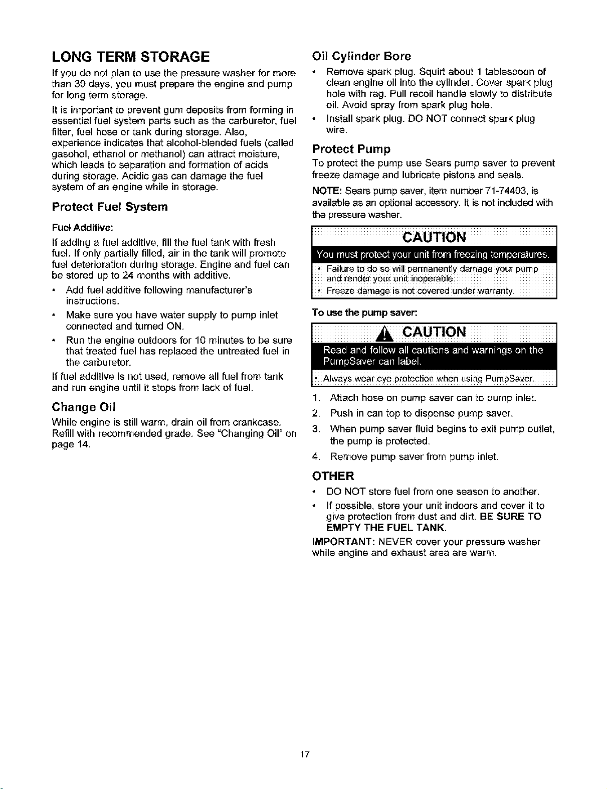
LONG TERM STORAGE
If you do not plan to use the pressure washer for more
than 30 days, you must prepare the engine and pump
for long term storage.
It is important to prevent gum deposits from forming in
essential fuel system parts such as the carburetor, fuel
filter, fuel hose or tank during storage. Also,
experience indicates that alcohol-blended fuels (called
gasohol, ethanol or methanol) can attract moisture,
which leads to separation and formation of acids
during storage. Acidic gas can damage the fuel
system of an engine while in storage.
Protect Fuel System
Fuel Additive:
If adding a fuel additive, fill the fuel tank with fresh
fuel. If only partially filled, air in the tank will promote
fuel deterioration during storage. Engine and fuel can
be stored up to 24 months with additive.
Add fuel additive following manufacturer's
instructions.
Make sure you have water supply to pump inlet
connected and turned ON.
Run the engine outdoors for 10 minutes to be sure
that treated fuel has replaced the untreated fuel in
the carburetor.
If fuel additive is not used, remove all fuel from tank
and run engine until it stops from lack of fuel.
Change Oil
While engine is still warm, drain oil from crankcase.
Refill with recommended grade. See "Changing OiF on
page 14.
Oil Cylinder Bore
Remove spark plug. Squirt about 1 tablespoon of
clean engine oil into the cylinder. Cover spark plug
hole with rag. Pull recoil handle slowly to distribute
oil. Avoid spray from spark plug hole.
Install spark plug. DO NOT connect spark plug
wire.
Protect Pump
To protect the pump use Sears pump saver to prevent
freeze damage and lubricate pistons and seals.
NOTE: Sears pumpsaver, item number 71-74403, is
available as an optional accessory. It is not included with
the pressurewasher.
, Freeze damage is not covered underwarrant3
To use the pump saver:
CAUTION
1. Attach hose on pump saver can to pump inlet.
2. Push in can top to dispense pump saver.
3. When pump saver fluid begins to exit pump outlet,
the pump is protected.
4. Remove pump saver from pump inlet.
OTHER
DO NOT store fuel from one season to another.
If possible, store your unit indoors and cover it to
give protection from dust and dirt. BE SURE TO
EMPTY THE FUEL TANK.
IMPORTANT: NEVER cover your pressure washer
while engine and exhaust area are warm.
17

18
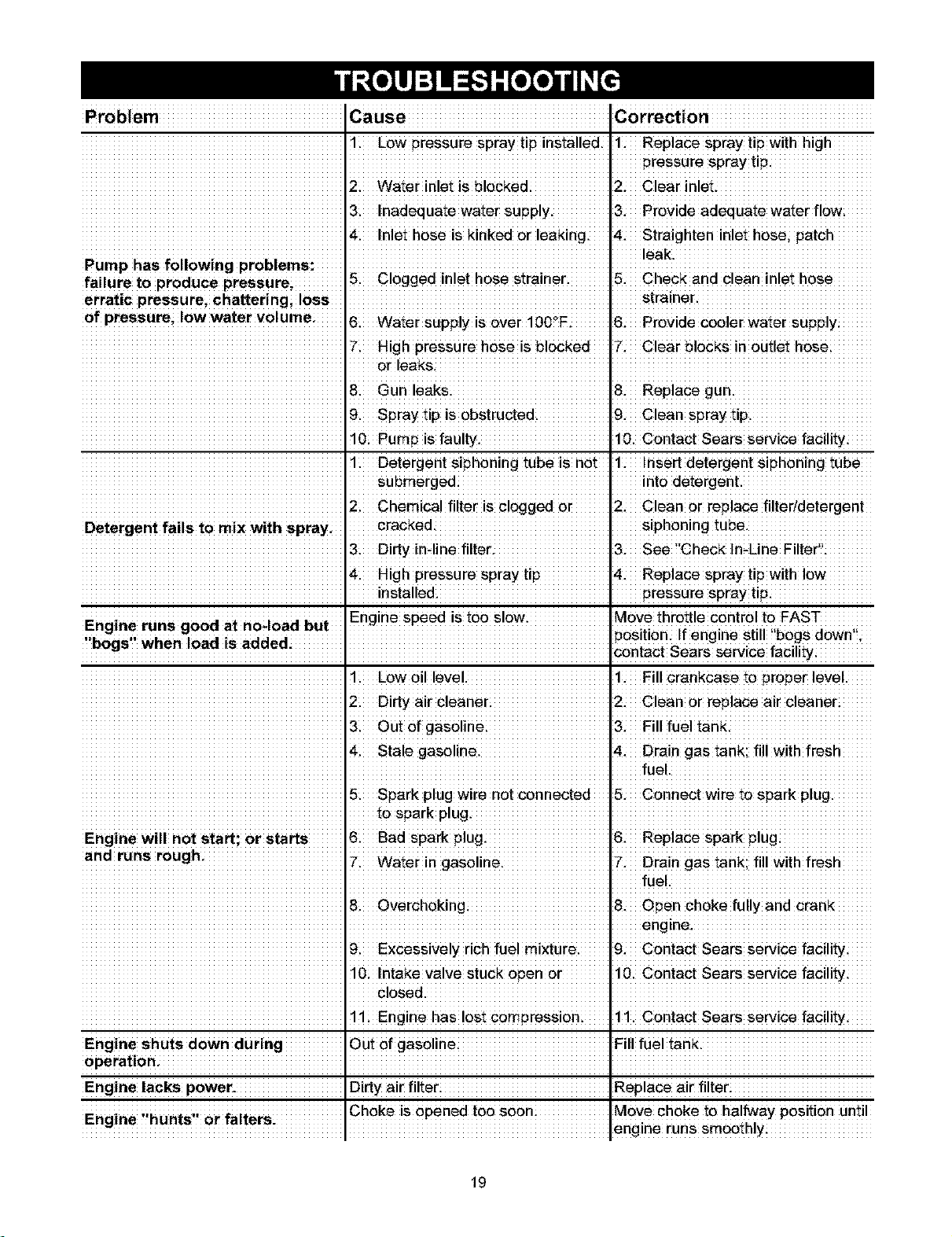
Problem Cause Correction
1. LOWpressure spray tip installed. !. Rep!ace Spray t!pWith high
pressure spray tip.
2i water inlet is bleckedi 2. Clearinleti
3. inadequate water supply. 3. provide adequate water f!_
4_ Inlet hose is kinked or leaking. 4. Straighten inlet hose; patch
i leak.
Pump has following problems: .....................................................................................................................
fa ure tO produce pressure 5. c 0gged in et hose Stra net 5" Check and clean net hose
erratic pressurei chatteringi !0ss ,strainer •
Of pressurei!o TM water v0!umei 6i water supply isever i00_F. 16. Provide cooler water supply
High pressure hose is blocked 7. clear blocks in Outlet
orleaks, i
8i Gunleaksi 8. Replace gun.
9. spray tip is Obstructed. 9. clean spray tip.
10i Pump is faulty. 10. Contact Sears service facility:
li Detergent Siphoning tube is not 1. Insert detergent siphoning tube
submerged into detergent.
2. Chemica! fi!ter is clogged or 2. Clean or replace filter/detergent
Detergent fails to mix with sprayi cracked: siphoning tube.
3i Dirty in-line filter. 3. see !'Check In;Line Filter'!i
4. High pressure spray tip 4. Rep!ace splay tip with !ew
installedi pressure spray tip:
Eh in r n _h i _ ; IEngine speed is too slowi Move throttle control te FAST
g e u sg0oeat 0_0aoeut i _osition if engine still l,bogs d0Wnil,
,bogs, when load is added: Contact sears service facility:
!. Low Oil love!. !. Fi!l Crankcase _ proper love!.
2i Dirty air cleaner; 2. Clean or replace air cleaner;
3 outefgasolinei 3. Fillfueltank.
4. Stale gase!ine. 4. Drain gas tank; fi!! with fresh
fuel.
5 spark plug wire not connected 5. Connectwi_ _o sparkp!ug.
Engine will net start; or Starts & Bad spark plug: 6. Replace spark plug:
andron ough
" I Wateii" IZ. Drain gastank; fill with fresh
fuel.
8i Overchoking; 8. Open choke fully and cran_
engine.
9. Excessive!y rich _e! mixture. 9. C0ntaCt sears Se_iCe facility
10i Intake valve stuck open or 10. Contact Sears service facility:
CloSed. I
!1 Engine has !est compression. !!. Contact sears se_ice facility4
Engine Shuts d0wn during Out Ofgasoline Fill fuel tank.
OperatiOn; I
Engine lacks power. Dirty air filter_ Replace air filter_
Ehine 'ihunts" 0r faiters Choke isopened too soon: ,M0Ve Choke to halfway pOSitionuntil
iI e,gine runs S_00thly
19

CRAFTSMAN 3000 PSI Pressure Washer 580.753000
Main Unit -- Exploded View and Parts List
I2÷ ÷L
l°o o!
-_7
Item Part # Description Item Part # Description
1 M190156GS BASE 12 192796GS KIT, Chem Hose & Filter
2 M187602GS HANDLE 13 192199GS ASSY, Extension
3 187606GS BILLBOARD 14 B1862BGS GUN
4 192648GS ASSY, Complete Hose Reel Kit 15 B5167GS HOSE
5 194004GS KIT, Inlet, Hose, Grdn, Srv 16 194298GS THERMAL RELIEF
6 192134GS KIT, Engine Mounting Hardware 17 190668GS KIT, Handle Fasteners
7 95457GS ADAPTER, Hose 18 192553GS KIT, Vibration Mount
8 192131GS KIT, Pump Mounting Hardware 19 192526GS KIT, Wheel
9 194236CGS NOZZLE, Turbo 20 23139DGS KEY
10 194062GS PUSHNUT 21 194003GS ASSY, Pump (see page21)
11 B5646GS KIT, SprayTips 900 NSP ENGINE
Items Not Illustrated .......................................... Optiona! Accessories Not !!!ustrated
Part# Description 7!7_02G$ HoSe Ree!
!94!90GS MANUALi ownerls 7!74403GS Pump save[
194420GS KIT; Decals T17430OGS HOUse Wash COnCentrate
AB3061BGS OIL Bottle (makes 4 gallons)
Deck Wash
Opti0na! Accessories Not illustrated (makes 2 gallons)
717518ZGS Garden Hese Ouick C0nnect 7174302GS vehicle/Beat Wash
7_7519ZGS Accessory QUick connectConcentrate (makes 4 gallons)
7t75199GS Rotating Brush Kit 7174303GS DegreaserConcentrate
7t75115GS 25' Replacement Hose (makes 4 gallons)
.......... 7175116GS .........O Ring Repair Kit ................................... 7174307GS ......... MoldlMildewCencentrate
7174400GS Turbo Nozzle (makes 2 gallons)
7_74401GS 25' Extension Hese
2O

CRAFTSMAN 3000 PSI Pressure Washer 580.753000
Pump -- Exploded View and Parts List
iiii_iiiiiiiii
I
iiiiiiiiii iiiiiiiiiiiiiii
iiiiiQ
iiiiiiiiii_
Item Part # Description Item Part #
21 194434GS O-RING A 190657GS
22 190639GS SPACER B 192914GS
24 190640GS WASHER C 194425GS
42 190646GS PISTON, Guide D 194426GS
50 191441GS VENT CAP, with O-Ring E 194427GS
63 194435GS O-RING F 193126GS
70 190654GS PUMP HEAD
71 190655GS GRUB SCREW & WASHER
72 190656GS OIL BOTTLE
Description
KIT, CHECK VALVE
KIT, CHEMICAL INJECT
KIT, SEAL OIL
KIT, INJECTOR
KIT, BALL & SPRING
KIT, UNLOADER
NOTE: Item letters A - F are service kits and include
all parts shown within the box.
21
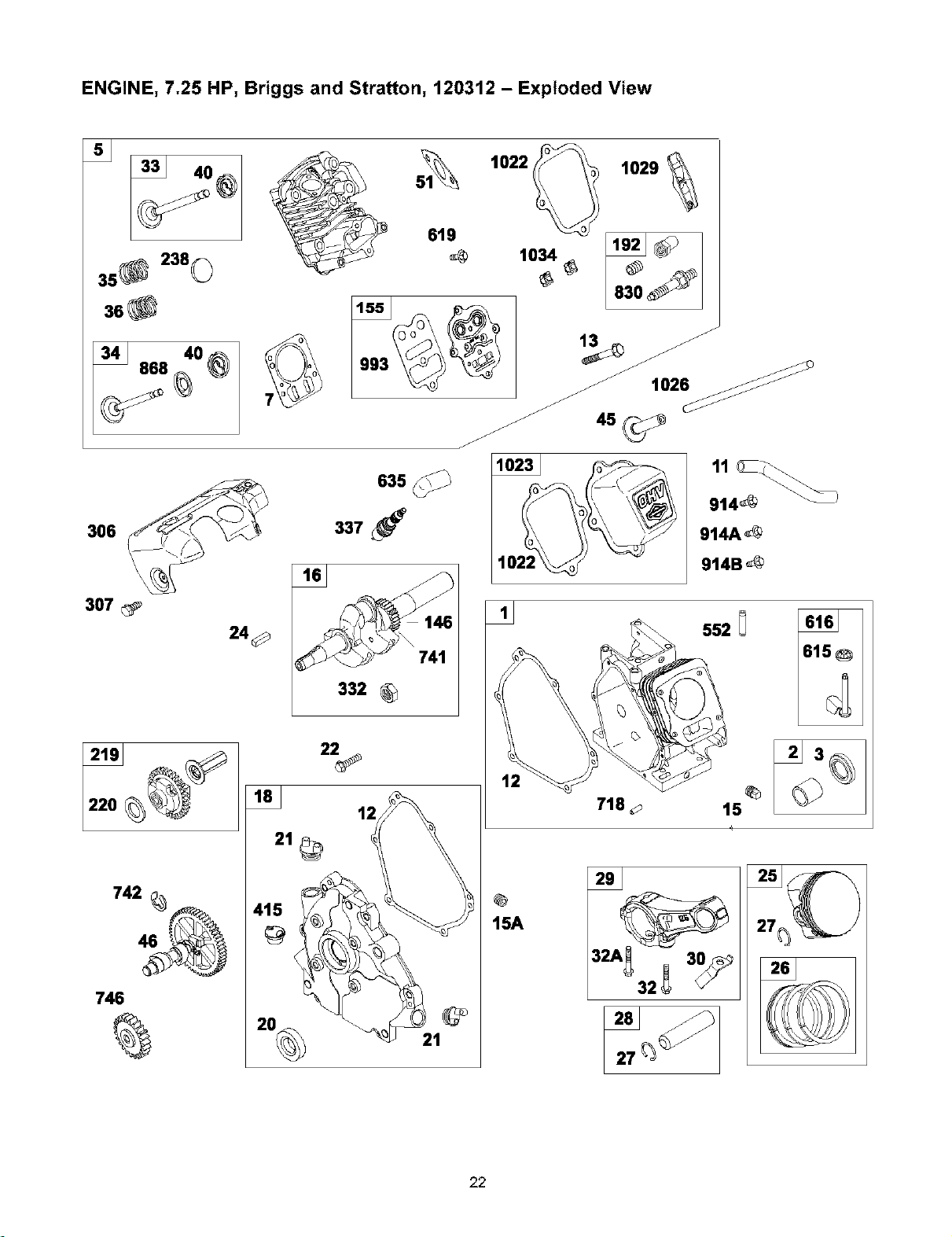
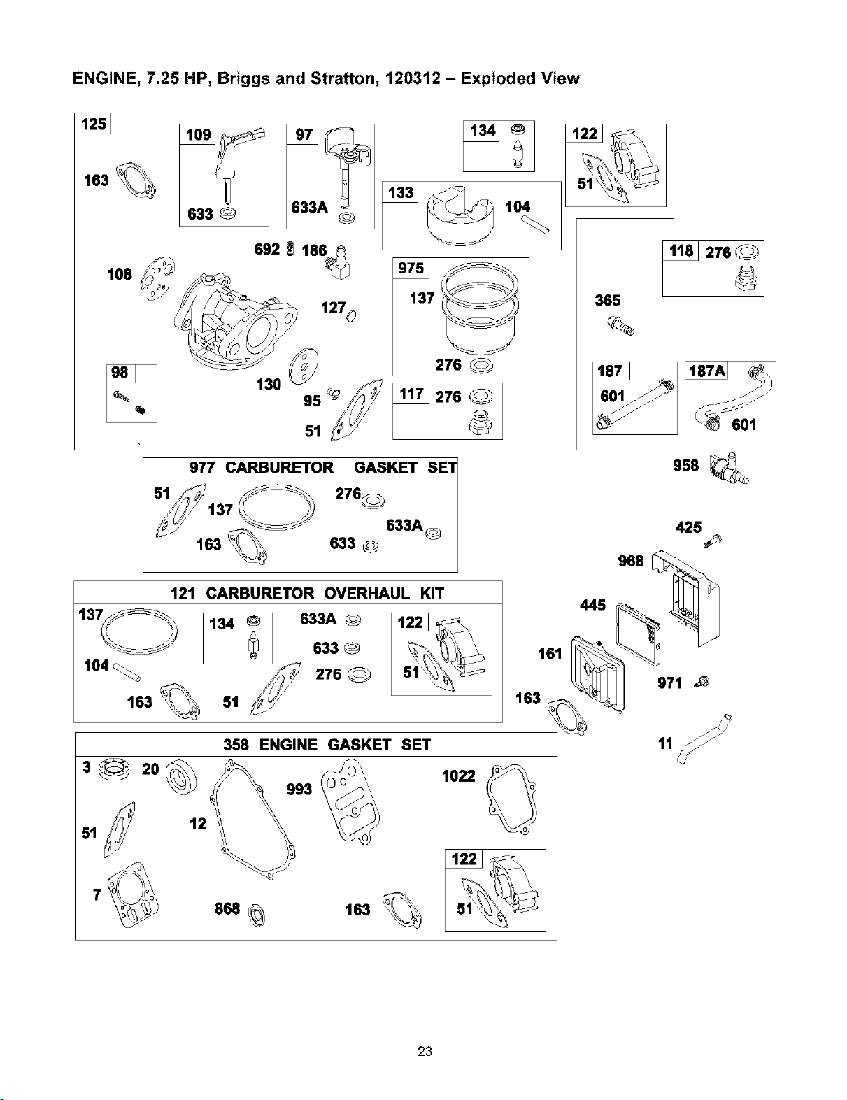
ENGINE, 7.25 HP, Briggs and Stratton, 120312 - Exploded View
3s® 230©
36_
300_
307
24 0
742
746
1029
332
22
12
415
@
20_ 21
619
1034 1_ _ I
718
15A
3,,_32_3_
22
ENGINE, 7.25 HP, Briggs and Stratton, 120312 - Exploded View
163 %
108
633 @
692 i 186_
127o
130 95 _
104
137
276
51
977 CARBURETOR GASKET SET
276_
633A@
163 633 0
121 CARBURETOR OVERHAUL KIT
-_ 033A® 1_ _ I
633 @ 51_
104 _ 276
163 % 51
161
163
358 ENGINE GASKET SET
7
868 _ 163 %
1022
365
276
601
958
425
445 968 _
11
23
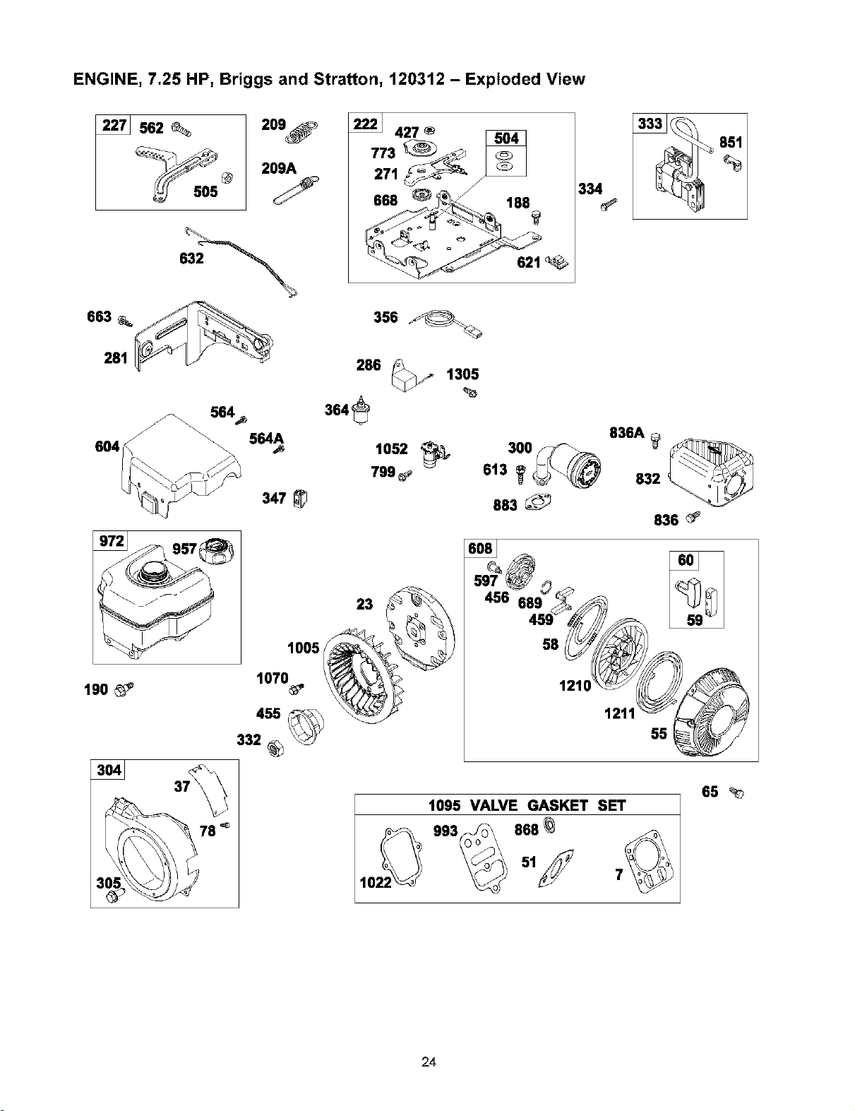
ENGINE, 7.25 HP, Briggs and Stratton, 120312 - Exploded View
562
209_
209A
663 __
281
222_ 427
271
355
286 _/ 1305
334
564A
604 \\
190_
78 "_
347_
1005
1070
1052
799#,
23
3oo_-_
613 _ _
883_
836A
832_
836_'
1095 VALVE GASKET SET
858
65
24
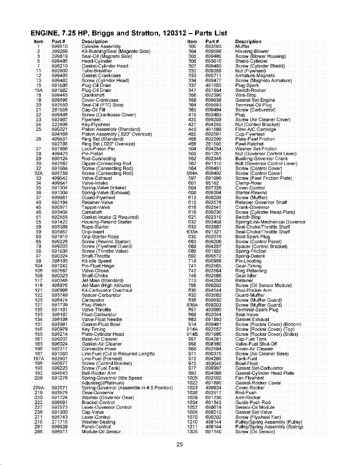
ENGINE, 7.25 HP, Briggs and Stratton, 120312 - Parts List
Item Parts Description Item Part# Description
_99510 Cylinder Assembly 300 693593 Muffler
2 399269 Kit_BushinglSeai (Magneto Side)304 699598 Housing-Blower
3 2998!9 Seal-Oi! (Magneto 305 699480 Screw (Blower Housing)
5 699486 Head-Cy!inder 306 693610 Shield-Cylinder
6982 !O Gasket-Cy!inder Head 307 699483 Screw (Cylinder $hieid)
41692600 Tube-Breather 332 699389 Nut (Flywheel)
42 699485 Gasket-Crankcase 333 696711 Armature-Magneto
_3 699482 Screw (Cylinder Head)334 6994_7 Screw (Magneto Armature)
_5 691686 Ptug-Oil Drain 337 491055 Plug-Spark
15A _91682 P!ug-Oil Drain 347" 697854 Switcl_Recker
i6 699445 Crankshaft 356 692390 Wire-Stop
48 699596 Cover-Crankcase 358 699638 Gasket Set-Eng!se
20 692550 Sea!*Oil (PTO Side)364 696693 TerminaFOi! P!u£
42_ 699298 Screw (Ak Cleaner Cover)
24 222698 Key_Flywheel 427` 694255 Nut (Centre[ Bracket)
25690021 Piston Assembly _Standard)445 49 !588 Fiffer-A/C Cartridge
694168 Piston Assembly (020'[ Oversize)455 692591 C_!ywhee!
26499631 Ring Set _Standard)486 692299 P!ate*Pawl
23 499423 PimPiston 58_ Nut (Governor Oontrol Lever)
29 _90124 Red-Connecting 552 692348 Bushing-Governor Cran k
30 _92562 Dipper-C#nnecting Rod 562 69! 112 Bolt (Governor Controt Lever)
32 691684 Screw (Connecting Rod)564 699491 Screw (Centre! Cover)
32A 695759 Screw (Co#nesting Rod)564A 699492 Screw (Centre! Cover)
33499642 Valve-Exhaust 597 69!696 Screw (Paw ! Fdction Plate)
643 699289 Screw (Muffler)
40 692"194 RetainerWalve 645 692576 Retainer-Governer
45690977 Tappet-Valve 6_i6 692547 Crank_Governo_
46 693404 Camshaft 649 699230 Screw (Cylinder Head
53 693389 Rope-Starlet 633 693887 Seal-ChokeiTSro_le S haft
59 89595_ Gripqnsert 633A 691621 $eaFGhokeiThrottle S haft
60 _919!5 Grip*Starte_ Rope 635 692076 Boot-Spark Plug
65 699228 Screw (Rewind Starter)663 699206 Screw (Centre! Panel)
78 699205 Screw (Flywheel Guard)668 694257 Spaser (Centre! Bracket)
#
93 398t85 KitqdteSpeed 7_3 690959 PimEoeating
741 692565 Gear-Timing
188 _92587 Valve-Choke 742 692564 Ring-Retaining
109 690023 Shaft-Choke 746 692568 Gear-Idler
117 690048 Jet-Main _Standard)773 694288 Reta!ser
118 498976 Jet*Main _High Altitude)799 699202 Screw (Oil Sensor Module)
121 696998 Kit-Carburetor Overhaul 830 694544 Stud-Rocker Arm
122 693749 Spacer-Carburetor 832 693583 Guard-Muffler
125 698474 Carburetor 836 699632 Screw (Muffler Guard)
"127 _91739 Plug-We!oh 836A 699293 Screw (Muffter Guard)
130 691181 Vaive-Throltle 85! 493880 Terminal-Spark P!ug
133 398187 Float-Carburetor 868 692044 Seal*Valve
134 $98188 Valve*Float Needte 883 691893 Gasket-Exhaust
155 69821 _ Plate-Cylinder Head 9!_S 691688 Screw (Rocker Cover)
"16! 957` 694261 Cap-Fuel
163 _96024 Gasket-Air Cteanet 988 698180 Valve_Fue!
186 692317 Connector-Hose 968 692584 Cover-Air C_eaner
"18_ 691050 Line-Fue_ 97! 690370 Screw (Ai_ Cleaner Base)
999220 Screw (Fuel Tank} 9_7` 696997 Gasket Set-Carbureto_
192 _94543 Batl-Roeke_Arm 993 694088 Gasket-Cytinde_ Head Plate
289 _91278 Spring-Govemo_ (tdte Speed !085 692592 FamFlywheeI
Adjusting)(P!atinum) !022 69!890 Gasket-Rocker Cover
209A 692571 Spring-Governor (Assemble !n #6 Position)!023 499924 Cover-Rocker
219 693578 Gear_Govemer 1026 693817 Red*F'ush
227 992573 Lever-Governe_ _052 698674 Sensor-Oi_ Module
238 _91306 Cap_Val_e _69_ 6982_5 Gask_Set-Vaive
271 _95743 Lever-Control 1070 699282 Screw (Flywheel Fan)
286 6986!1 Module_Oi!Sensor 1305 691'140 Screw (OilSenser)
25
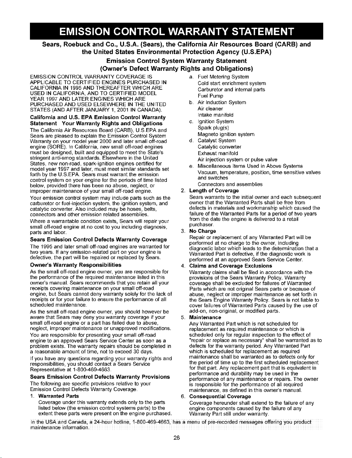
Sears, Roebuck and Co., U.S.A. (Sears), the California Air Resources Board (CARB) and
the United States Environmental Protection Agency (U.S.EPA)
Emission Control System Warranty Statement
(Owner's Defect Warranty Rights and Obligations)
EMISSION CONTROL WARRANTY COVERAGE _S a, Fuel Metering System
APPLICABLE TO CERTiFiED ENGINES PURCHASED _N
CALIFORNIA IN 1995 AND THEREAFTER WHICH ARE
USED _NCALIFORNIA, AND TO CERTIFIED MODEL
YEAR 1997 AND LATER ENGINES WHICH ARE
PURCHASED AND USED ELSEWHERE IN THE UNITED
STATES (AND AFTER JANUARY 1, 2001 IN CANADA).
California and U.S. EPA Emission Control Warranty
Statement Your Warranty Rights and Obligations
The California Air Resources Board (CARB), U.S.EPA and
Sears are pleased to explain the Emission Control System
Warranty on your model year 2000 and later small off-road
engine (SORE). tn California, new small off-road engines
must be designed, built and equipped to meet the State's
stringent anti-smeg standards. Elsewhere in the United
States, new non-road, spark-ignition engines certified for
model year 1997 and later, must meet similar standards set
forth by the U.S.EPA. Sears must warrant the emission
control system on your engine for the periods of time listed
below, provided there has been no abuse, neglect, or
improper maintenance of your small off-road engine.
Your emission control system may include parts such as the
carburetor or fuel-injection system, the ignition system, and
catalytic converter. Also included may be hoses, belts,
connectors and other emission related assemblies.
Where a warrantable condition exists, Sears will repair your
small off-road engine at no cost to you including diagnosis,
parts and labor.
Sears Emission Control Defects Warranty Coverage
The 1995 and later small off-road engines are warranted for
two years. If any emission-related part on your engine is
defective, the part will be repaired or replaced by Sears.
Owner's Warranty Responsibilities
As the small off-road engine owner, you are responsible for
the performance of the required maintenance listed in this
owner's manual. Sears recommends that you retain all your
receipts covering maintenance on your small off-road
engine, but Sears cannot deny warranty solely for the lack of
receipts or for your failure to ensure the performance of all
scheduled maintenance.
As the small off-road engine owner, you should however be
aware that Sears may deny you warranty coverage if your
small off-road engine or a part has failed due to abuse,
neglect, improper maintenance or unapproved modifications.
You are responsible for presenting your small off-road
engine to an approved Sears Service Center as soon as a
problem exists. The warranty repairs should be completed in
a reasonable amount of time, not to exceed 30 days.
ff you have any questions regarding your warranty rights and
responsibilities, you should contact a Sears Service
Representative at 1-8004694663.
Sears Emission Control Defects Warranty Provisions
The following are specific provisions relative to your
Emission Control Defects Warranty Coverage.
1, Warranted Parts
Coverage under this warranty extends only to the parts
listed below (the emission control systems parts) to the
extent these parts were present on the engine purchased.
Cold start enrichment system
Carburetor and internal parts
Fuel Pump
b. Air reduction System
Air cleaner
tntake manifold
c. tgnition System
Spark plug(s)
Magneto ignition system
d. Catalyst System
Catalytic converter
Exhaust manifold
Air injection system or pulse valve
e. Miscellaneous ffems Used in Above Systems
Vacuum, temperature, position, time sensitive valves
and switches
Connectors and assemblies
2. Length of Coverage
Sears warrants to the initial owner and each subsequent
owner that the Warranted Parts shall be free from
defects in materials and workmanship which caused the
failure of the Warranted Parts for a period of two years
from the date the engine is delivered to a retail
purchaser.
3. No Charge
Repair or replacement of any Warranted Part will be
performed at no charge to the owner, including
diagnostic labor which leads to the determination that a
Warranted Part is defective, if the diagnostic work is
performed at an approved Sears Service Center.
4. Claims and Coverage Exclusions
Warranty claims shall be filed in accordance with the
provisions of the Sears Warranty Policy. Warranty
coverage shall be excluded for failures of Warranted
Parts which are not original Sears parts or because of
abuse, neglect or improper maintenance as set forth in
the Sears Engine Warranty Policy. Sears is net liable to
cover failures of Warranted Parts caused by the use of
add-on, non-original, or modified parts.
5, Maintenance
Any Warranted Part which is not scheduled for
replacement as required maintenance or which is
scheduled only for regular inspection to the effect of
"repair or replace as necessary" shall be warranted as to
defects for the warranty period. Any Warranted Part
which is scheduled for replacement as required
maintenance shall be warranted as to defects only for
the period of time up to the first scheduled replacement
for that part. Any replacement part that is equivalent in
performance and durability may be used in the
performance of any maintenance or repairs. The owner
is responsible for the performance of all required
maintenance, as defined in this owner's manual.
6. Consequential Coverage
Coverage hereunder shall extend to the failure of any
engine components caused by the failure of any
Warranty Part still under warranty.
tnthe USA and Canada; a 24_hour hedinei 1_800_469_4663, has a menu of pre,recorded messages offering you product
maintenance inf0rmati0n.
26

27
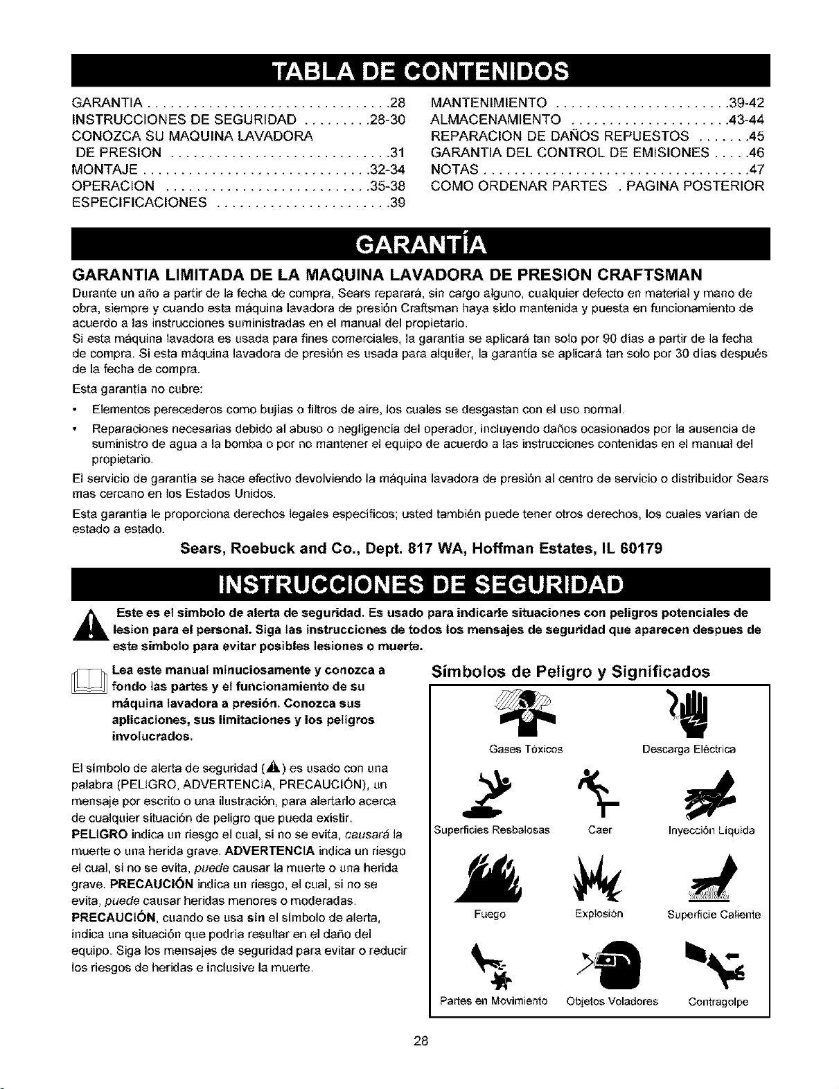
GARANTIA ................................ 28
INSTRUCCIONES DE SEGURIDAD ......... 28-30
CONOZCA SU MAQUINA LAVADORA
DE PRESION ............................. 31
MONTAJE .............................. 32-34
OPERACION ........................... 35-38
ESPECIFICACIONES ....................... 39
MANTENIMIENTO ....................... 39-42
ALMACENAMIENTO ..................... 43-44
REPARACION DE DAISES REPUESTOS ....... 45
GARANTIA DEL CONTROL DE EMISIONES ..... 46
NOTAS ................................... 47
COMe ORDENAR PARTES . PAGINA POSTERIOR
GARANTIA LIMITADA DE LA MAQUINA LAVADORA DE PRESION CRAFTSMAN
Durante un a_o a partir de la fecha de compra, Sears reparar_, sin cargo algune, cualquier defecto en material y mane de
ebra, siempre y cuando esta m_quina lavadera de presi6n Cra_sman haya side mantenida y puesta en funcionamiento de
acuerdo alas instrucciones suministradas en el manual del propietario.
Siesta m_quina lavadera es usada para fines cemerciales, la garantia se aplicar_ tan solo per 90 dias a partir de la fecha
de cempra. Siesta m_quina lavadora de presi6n es usada para alquiler, la garantia se aplicar_ tan solo per 30 dias despu6s
de la fecha de cempra.
Esta garantia no cubre:
Elementos perecederos come bujias o filtros de aire, los cuales se desgastan con el use normal.
Reparaciones necesarias debido al abuse o negligencia del operador, incluyende daSos ocasionados per la ausencia de
suministro de agua a la bomba o per no mantener el equipo de acuerdo alas instrucciones contenidas en el manual del
propietario.
El servicio de garantia se hace elective devolviendo la m_quina lavadera de presi6n al centre de servicio e distribuidor Sears
mas cercano en los Estados Unidos.
Esta garantia le proporciona derechos legales especificos; usted tambi6n puede tenet otros derechos, los cuales varian de
estade a estado.
Sears, Roebuck and Co., Dept. 817 WA, Hoffman Estates, IL 60179
Este es el simbolo de alerta de seguridad. Es usado para indicarle situaciones con peligros potenciales delesion para el personal. Siga las instrucciones de redes los mensajes de seguridad que aparecen despues de
este simboIo para evitar posibles Iesiones o muerte.
Lea este manual minuciosamente y conozca a
_ rondo Ias partes y et funcionamiento de su
m&quina tavadora a presibn. Conozca sus
aplicaciones, sus limitaciones y los peligros
involucrados.
El simbolo de alerta de seguridad (_) es usado con una
palabra (PEL_GRO, ADVERTENCIA, PRECAUCI6N), un
mensaje per escrito o una ilustraciSn, para alertarlo acerca
de cualquier situaciOn de peligre que pueda existir.
PELtGRO indica un riesge el cual, si no se evita, causar,_ la
muerte e una herida grave. ADVERTENGtA indica un riesgo
el cual, si no se evita, puede causar la muerte o una hedda
grave. PRECAUCl0N indica un riesge, el cual, si no se
evita, puede causar heridas menores o moderadas.
PREGAUGI6N, cuando se usa sin el simbole de alerta,
indica una situaciOn que podria resultar en el daho del
equipo. Siga los mensajes de seguridad para evitar e reducir
los riesgos de heridas e inclusive la muerte.
Simbotos de Peligro y Significados
Gases Toxicos DescargaElectrica
Z 5-
Superficies Resbalosas Caer Inyecci6nLiquida
Fuego Explosion Superficie Caliente
Partesen Movimiento Obietos Voladeres Contragelpe
28

En el estado de California es obligatorio, segon la ley, el use
3e apagachispas (Secci6n 4442 del C6digo de Recursos
Poblicos de California). Otros estados pueden tenet leyes
similares. Las leyes federales se aplican en tierras
Federales. Si equipa el silenciador con un apagachispas,
_=stedeber_ set mantenido en buenas condiciones de
_rabajo. Usted puede ordenar el apagachispas a traves de
su distribuidor de servicio autorizado Sears.
CUAND0 A_tADA COMBUs'riBLE
, Apague el generador (posici6n OFF) y dejele enfriar al menos
pot2 minutes antes de _emover ta tapa de la gasolina
I ADVERTENCIA I , Llene el tanque al aire libre: .............................................
El escape del motor de este producto contiene ,NO itene demasiade ei tanquei Permita ai men0s espaeio para
etementos quimicos reconocidos en el Estado de la expansi6n del combustible
California per producir c&ncer, defectos de nacimiento , Mantenga ta gasolina atejada de chispas, llamas abier_as;
u otros dat3os de t po reproduct vo. pilot,S taler y otras fuen_es de ignition
, NO encienda un eigarritlo _ fume
CUANDO OPERE EE EQU]PO
PELIGRO ,No inellne et meter 0 el equipe, de tal manera que la gasollna
se p_eda derramar.
, NO retie Itquidos i_flamables
CUANDO TRANSPORTE O REPARE EL EQUtPO
, Transporte o repare el equip0 c_n el tanque de ¢_rnbustib!e
vaeioi _cen la v_lvula papa apagar el €0mbustible apagada
(positiOn OFF)
CUANDO ALMACENE O GUARDE EL EQUIPO CON
COMBUS'I'IBLE EN EL "I'ANQUE
, Almacene alejad0 de ealde_as, est_asi ca_en'_aderes de agua
secaderas de [epa u etres aparatos electrod#mestices que
posean pilotes u etras fuentes de igni¢i6n, porque elles pueder_
eneender los Vapores de la gaselina
vapores nooivos.
ADVERTENCIA
de t_ contrarle podrian o¢t_rdr descargas et_ctricas fatales.
ADVERTENCIA
Mantenga la boquilla de rociado de 8 a 24 pul#adas de la
superfi¢ie de !impieza
' s_a extrernadamente Cuidadoso si usa la m_quina tavad0ra a
presi6n desde una escalera, andamle o cuaiquier supefficie
reletivamente inestabie:
• Et area de lirnpieza deberrJ tenet inciinacior_es y drenajes
adecuados para disrrlinuir ta pesibilidad de Caidas debid0 a
superfic!es resba!osas
, Opere y airnacene esta unidad sobre una superficie estable.
, Sujete la pisto_a de la hidroiavadora firmemente con ambas
manes ¢uand0 Utilice el {0Ciad0 a alta presi6n De esta manera
evitarrJ lesiones producidas par e_posible golpe de la pis_la
rociado cuando et sistema este presudzado:
ADVERTENCIA
29
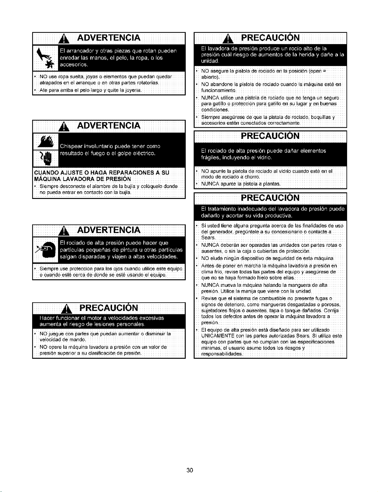
ADVERTENCIA
e cuande est_ berca de deride se esf_ usando et equip 0
PRECAUCION
PRECAUCION
,NO asegu_e fa pisloia de rociada en la posici6n (open =
ab!erto}.
' NO abandone Ja p!st0!a de ro¢!ad0 bUabdO !a m,cquina est_ eb
funcienarniebto
, NUNCA uiilice u_a pistola de rociado qua no tenga un seguro
Para gafJ[100 pi-0tec¢iOn para gatit!0 en su !ugar y en buenas
, Siempre aseg_rese de que la pistola de _ObiadO, boquittas y
accesoriOS
PRECAUCION
PRECAUCION
, Si Usted tiene alguna pregunta acerca de las finaiidades de use
de! generader, pregOnte!e a su coneesionario o bontacte a
' NUNCA deber_n sei-operadas las unidades _n partes rotas #
ausentes, e sin la caja o cubiertas de protecci6n:
,NO eluda n_ng0n dispesitivo de seguridad de esta maquina
i Antes de #0net en marCha !a m_quiaa tavado[a a pres(6n
blima fdo, revise todas !as gaffes de! equipo y aseg_rese de
qua be se haya formade hieto Sobre elias
, NUNCA mueva ia maquina haiande la mangue_-a de al_a
presion. Utilice la manija Rueviene con la unidad
, Revise qua el sistema de combustible no presente fugas o
signos de deterioro; come mangueras desgastadas e perosasi
sujetadores flojos o absents tapa e tanque daf_ad0S. Corrija
redes lOSdefectos antes de ogerar !a m_quina lavadora a
F)re_terl.
, El eqaipo de alta #reSi_r_ est_ diseeadO para ser Utilizado
UNiCAMENTE COnlas pastesautorlzadas sears si utiiiza este
eq#ipo con partes quen0 burnpla n con !as espebifibaCiebeS
mi#irnas, et usuari0 asurne redes lee riesgos
responsabitidades
30
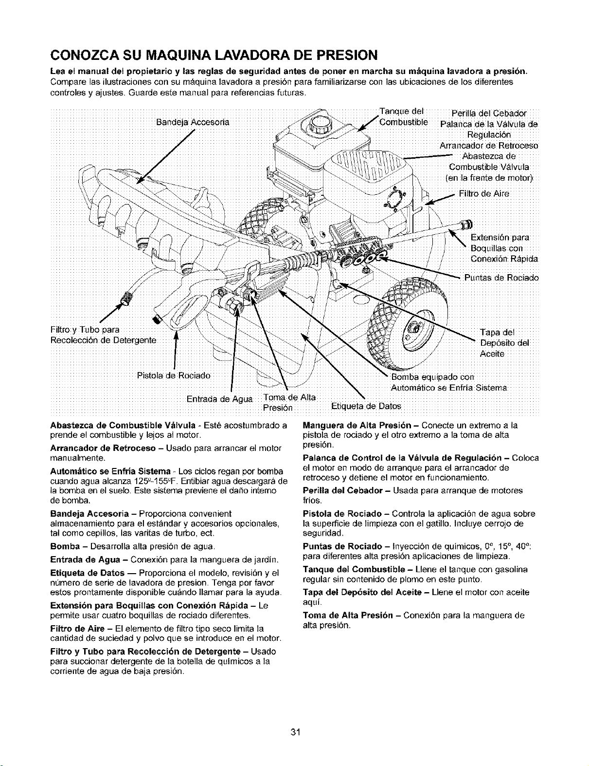
CONOZCA SU MAQUINA LAVADORA DE PRESION
Lea el manual del propietario y las reglas de seguridad antes de porter en marcha su m_quina lavadora a presibn.
Compare las ilustraciones con su m_quina lavadora a presi6n para familiarizarse con las ubicaciones de los diferentes
controles y ajustes. Guarde este manual para referencias futuras.
Bandeja Acceseria
_e del perilla del Cebador
Palanca de la 'v'_lvulade
Regu]aci_rr
Arrancador de Retroceso
Abastezca de
Combustibie V&lvula
(en la frente de motor)
.. Eiltre de Aire
Extensi6n para
3illas con
Conexi6n R_pida
Filtro y Tube para
RecolecciSrr de Detergente'
Tapa de!
Dep6sito del
Pisto!a de Rociado Bomba equipado con
Autom&tice se Enfria Sistema
EntradadeAgU_ TomadeAIta
Presi6n Etiqueta de Dates
Abastezca de Combustible V_tvula _Est6 acostumbrade a
prende el combustible y lejes al motor.
Arrancador de Retroceso - Usado para arrancar el motor
manualmente.
Autom_tico se Enfria Sistema - Los ciclos regan per bomba
cuando egua alcanza 125_-155'_F.Entibiar agua descargar_ de
la bomba en el suelo. Este sistema previene el dante interne
de bemba.
Manguera de Alta Presi6n - Conecte un extreme a la
pistola de reciado y el otro extreme a la tema de alta
presi6n.
Patanca de Control de ta V&tvuta de Regutacibn - Coloca
el motor en mode de arranque para el arrancador de
retreceso y detiene el motor en funcionamiente.
Parilla del Cebador - Usada para arranque de meteres
fries.
Barrdeja Accesoria - Preporciona convenient
almacenamiente para el est_ndar y accesorios opcionales,
tal come cepillos, las varitas de turbo, ect.
Bomba - Desarrolla alta presi6n de agua.
Entrada de Agua - Conexi6n para la manguera de jardin.
Etiquata de Dates -- Properciona el modele, revisi6n y el
numero de serie de lavadora de presion. Teega per favor
estes prentamente disponible cu_nde Ilamar para la ayuda.
Exterrsibrr para Boquiltas con Correxibn R&pida - Le
permite usar cuatro boquillas de rociado diferentes.
Filtro de Aira - El elemente de filtro ripe sece limita la
cantidad de suciedad y pelve que se introduce en el motor.
Filtro y Tubo para Recolecci6n de Detergente - Usado
para succionar detergente de la botella de quimicos a la
cerriente de egua de baja presi6n.
Pistola de Rociado - Controla la aplicaci6n de agua sobre
la superficie de limpieza con el gatillo. Incluye cerreje de
seguridad.
Puntas de Rociado - Inyecci6n de quimices, 0e, 15°, 40°:
para diferentes alta presi6n aplicaciones de limpieza.
Tanque del Combustible -Llene el tanque con gasolina
regular sin centenide de plome en este punto.
Tapa del Dap6sito det Aceite - Llene el motor con aceite
aqui.
Toma de Alta Prasi6n - Conexi6n para la manguera de
alta presi6n.
31
Su m_quina lavadora a presi6n requiere de cierto ensemble
y estarA lista pare set usada unicamente despu_s de haber
depositado el combustible y el aceite recomendado.
Si tiene problemas con et ensambte de su m&quina
lavadora a presibn, Ilame a la linea de ayuda de ta
m_quina tavadora a presibn at 1-800-222-3136.
IMPORTANTE: Cualquier intento de hacer funcionar el
motor sin haber depositado el aceite recomendado resultar_
en falla del mismo.
RETIRE LA MAQUINA LAVADORA A
PRESION DE LA CAJA
1.
2.
3.
4.
Retire la caja de pares enviada con su mAquina
lavadora a presi6n.
Corte dos esquinas opuestas el extremo de la manija
guia de la caja, de la parte superior a la inferior, de tel
forma que el panel pueda set doblado hacia abajo.
Saque la m_quina lavadora a presi6n de la caja.
Revise la caja para vet si existen pares sueltas
adicionales.
CONTENIDO DE LA CAJA
Revise el contenido de la caja. Si alguna de las partes no
estA presente o estA daf_ada, Ilame a la linea de ayuda de
la m_quina lavadora a presi6n el 1-800-222-3136.
La Unidad Principal
Manubrio
Bandeja Accesoria Pl_stica
La Manguera de Alta Presi6n
Pistola de Rociado
Los Componentes del Carrete de la Manguera
Boquilla a Chorro de Conexi0n R&pida
ExtensJdn de la Lanza con las PJezas de Conexi0n
R_pida
Aceite para Motor
Bolsa de accesorios (incluye Io siguiente):
Manual del Propietario
Tarjeta de Registro del Propietario
Bolsa con 4 Lanzas de Conexiones R_pidas
Multicolores
Piezas para la manubrio (incluye Io siguiente):
Perno del Soporte
Perno "L"
Perilla PIAstica (2)
Gancho "J"
Clip Detergente de la Manga
Auto Utiliza Enrosca (4)
Familiaricese con cada parte antes de ensamblar la
m_quina lavadora a presi6n. Compare el contenido con la
ilustraci6n de la pAgina 31. Si alguna de la partes NO estA
presente o se encuentra daf_ada, Ilame a la linea de ayuda
de la m_quina lavadora a presi6n el 1-800-222-3136.
MONTAJE DE LA MAQUINA
LAVADORA A PRESION
La gran mayoria de su m_quina lavadora a presi6n
Craftsman ha sido ensamblada en la f_brica. Sin embargo,
usted deberA Ilevar a cabo los siguientes procedimientos
antes de porter en funcionamiento su m_quina lavadora a
presi6n:
1. Llene y mande en tarjeta de matricula.
2. Conecte manubrio y bandeja accesoria a unidad
principal.
3. Aflada aceite al motor.
4. Aflada gasolina el tanque de combustible.
5. Conecte manguera a alta presi6n a pistola rociadora y a
bomba.
6. Conecte el suministro de ague a bomb&
7. Conecte boquilla la extensi6n al pistola rociadora.
8. Selecto/conecta r_pido conecta boquilla a la extensi6n
de la boquilla.
9. Conecte manga carrete seg_m hoja de instrucci6n
incluy6 en la caja de carrete de mange.
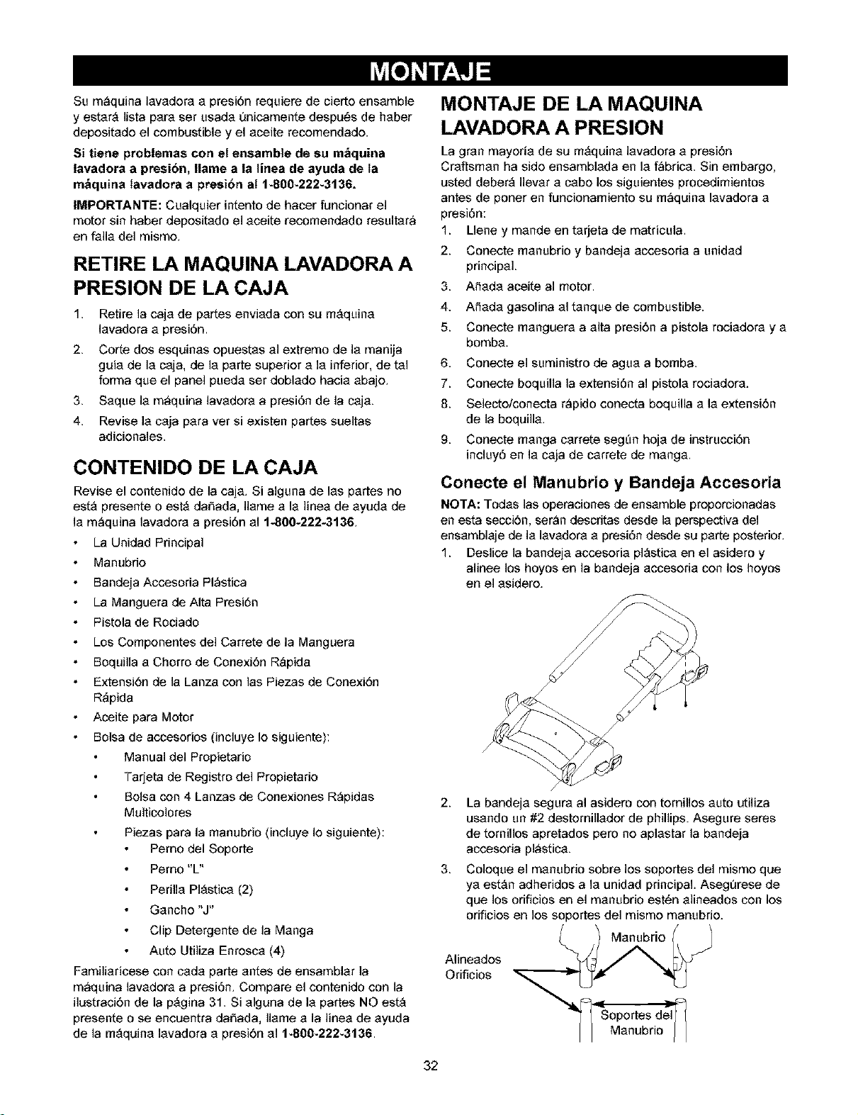
Conecte el Manubrio y Bandeja Accesoria
NO'I'A: Todas las operaciones de ensemble proporcionadas
en esta secci6n, ser_n descritas desde la perspectiva del
ensamblaje de la lavadora a presi6n desde su parte posterior.
1. Deslice la bandeja accesoria plAstica en el asidero y
alinee los hoyos en la bandeja accesoria con los hoyos
en el asidero.
2.
3.
/
La bandeja segura al asidero con tomillos auto utiliza
usando un #2 destornillador de phillips. Asegure seres
de tornillos apretados pero no aplastar la bandeja
accesoria pl_stica.
Coloque el manubrio sobre los soportes del mismo que
ya estAn adheridos a la unidad principal. Asegurese de
que los orificios en el manubrio estC_nalineados con los
oriflcios en los soportes del mismo manubrio.
Manubrio
Alineados
Orificios
Soportes del
Manubrio
32
NOTA: Tal vez serA neceserio mover los soportes del
manubrio de un ledo e otre para elineer el manubrio de tel
manera que puede deslizarse sobre los soportes del mismo
manubrio.
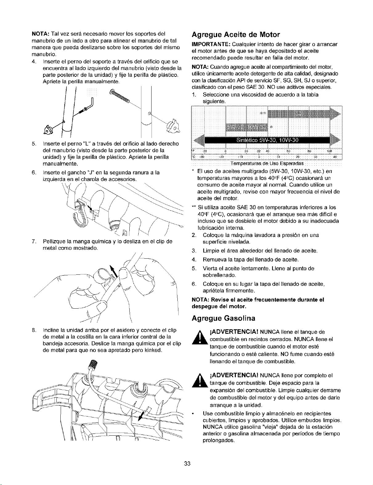
4. mserte el perno del soporte e trev6s del orificie que se
encuentre al lade izquierde del menubrio (viste desde le
parte posterior de le unided) y fije le perille de plAstice.
Apriete le perille manualmente.
J
5. lnserte el perno "L" a trav6s del orificio al lade derecho
del manubrie (viste desde le parte posterior de le
unidad) y fije le perille de plAstice. Apriete le perille
manuelmente.
6. inserte el ganche "J"en le segunda ranura e la
izquierde en el charole de eccesories.
7. Pellizque la mange quimica y Io deslize en el clip de
metal como mostrado.
/
8.
recline le unidad erribe por el asidero y conecte el clip
de metal ale cestille en la cara inferior central de le
bandeja eccesode. Deslice le mange quimice por el clip
de metal pare que no sea epretede pero kinked.
Agregue Aceite de Motor
IMPORTANTE: Cualquier intento de hacer girar o errancar
el motor antes de que se haye depesitede el aceite
recemendado puede resultar en falla del motor.
NO'I'A: Cuando agregue aceite al compertimiento del motor,
utilice t_nicamente aceite detergente de elta calidad, designade
con la clasificaci6n API de servicie SF, SG, SH, SJ e superior,
clesificado con el peso SAE 30. NO use editives especieles.
1. Selecciene une viscesided de acuerdo e le tebla
siguiente.
Tempe[aturas de Use Espemdas
* El use de aceites multigrado (5W-30, 10W-30, etc.) en
temperaturas mayores a los 40'_F (re'C) ocasionarA un
consume de aceite mayor al normal Cuando utilice un
aceite multigrado, revise con mayor frecuencia el nivel de
aceite del motor.
** Si utiliza aceite SAE 30 en temperatures inferieres a los
40_F (4'_C), ecasienarA que el arranque sea mAs dificil e
incluso que se desbiele el motor debide a su inadecuada
lubricaci6n interne.
2. Coleque la mAquina lavedora a presi6n en una
superficie nivelada.
3. Limpie el Area alrededer del Ilenado de aceite.
4. Remueva la tepa del Ilenado de aceite.
5. Vierta el aceite lentamente. Llene al punto de
sebrellenado.
6. Coleque en su lugar la tapa del Ilenade de eceite,
apd6tela firmemente.
NOTA: Revise el aceite frecuentemente durante el
despegue del motor.
Agregue Gasotina
_k ADVERTENCIA! NUNCA Ilene el tanque de
combustible en recintos cerrados. NUNCA Ilene el
tanque de combustible cuande el motor est6
funcienando o est6 caliente. NO fume cuando est6
Ilenande el tanque de combustible.
_. ADVERTENCIA! NUNCA Ilene por completo el
tanque de combustible. Deje espacie pare la
expansi6n del combustible. Limpie cualquier derreme
de combustible del motor y del equipe antes de dame
erranque e la unidad.
Use combustible limpio y almac_nelo en recipientes
cubiertos, limpies y eprebedes. Utilice embudes limpies.
NUNCA utilice gasoline "vieja" dejade de le estaci6n
anterior e gesolina elmacenada per periodos de tiempo
prolengados.
33
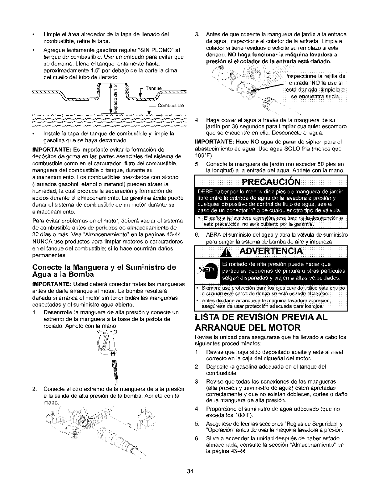
Limpie el Area alrededor de la tapa de Ilenado del 3.
combustible, retire la tapa.
Agregue lentamente gasolina regular "SIN PLOMO" al
tanque de combustible. Use un embudo para evitar que
se derrame. Lleee el tanque lentamente hasta
aproximadamente 1.5" por debajo de la parte la cima
del cuello del tubo de Ilenado.
Combustible
lnstale la tapa del tanque de combustible y limpie la
gasolina que se haya derramado.
IMPORTANTE: Es importante evitar la formaci6n de
dep6sitos de goma en las partes esenciales del sistema de
combustible como en el carburador, filtro del combustible,
manguera del combustible o tanque, durante su
almacenamiento. Los combustibles mezclados con alcohol
(llamados gasohol, etaeel o metanol) pueden atraer la
humedad, la cual produce la separaci6n y formaci6n de
_cidos durante el almacenamiento. La gasolina Acida puede
dafiar el sistema de combustible de un motor durante su
almacenamiento.
Para evitar problemas en el motor, deberA vaciar el sistema
de combustible antes de periodos de almacenamiento de
30 dias o mAs. Yea "Almacenamiento" en la p_ginas 43-44.
NUNCA use productos para limpiar motores o carburadores
en el tanque del combustible; si Io hace ocurdr_n dafios
permanentes.
Conecte la Manguera y et Suministro de
Agua a ta Bomba
IMPORTANTE: Usted deber_ conectar tedas las mangueras
antes de darle arranque al motor. La bomba resultarA
dafiada si arranca el motor sin tener tedas las mangueras
conectadas y el suministro agua abierto.
1. Desenrrolle la manguera de alta presi6n r conecte un
extremo de la manguera a la base de la _istola de
rociado. Apriete con la maee.
2.
Conecte el otto extremo de la manguera de alta presi6n
a la salida de alta presi6n de la bomba. Apriete con la
mano.
]
Antes de que conecte la manguera de jardin a la entrada
de agua, inspeccione el colador de la entrada. Limpie el
colador si tiene residuos o solicite su remplazo si est_
dafiado. NO haga funcionar la m_quina tavadora a
presi6n si el colador de la entrada est_ da_ado.
ilia de
i,
est_ dafiada; limpiela si
Haga correr el agua a travels de la manguera de su
jardin por 30 segundos para limpiar cualquier escembro
que se encuentre en ella. Descenecte el agua.
IMPOR'I'ANTE: Hace NO agua de parar de siphon para el
abastecimiento de agua. Use agua SOLO fria (menee que
100°F).
5. Conecte la manguera de jardin (no exceder 50 pies en
la Iongitud) a la entrada del agua. Apriete con la mano.
PRECAUCION
6. ABRA el suministe del agua y abra la vAIvula de suministro
para purgar la sistema de bomba de aire y impureza.
LISTA DE REVISION PREVIA AL
ARRANQUE DEL MOTOR
Revise la unidad para asegurarse que ha Ilevado a cabo los
siguientes procedimientce:
1. Revise que haya sido depositado aceite y est6 al nivel
correcto en la caja del cig0eilal del motor.
2. Deposite la gasolina adecuada en el tanque del
combustible.
3. Revise que todas las conexioees de las mangueras
(alta presidn y suministro de agua) estC_napretadas
correctamente y que no existan dobleces, cortes o dafio
de la manguera de alta presidn.
4. Proporcione el suministro de agua adecuado (que no
exceda los 100'_F).
5. Asegurese de leer las seccioees "Reglas de Seguddad" y
"Operaci6n"antes de usar la mAquina lavadora a presi6n.
6. Siva a encender la unidad despu¢_s de haber estado
almacenada, consulte la seccidn "Almacenamiento" en
la p_gina 43-44.
34
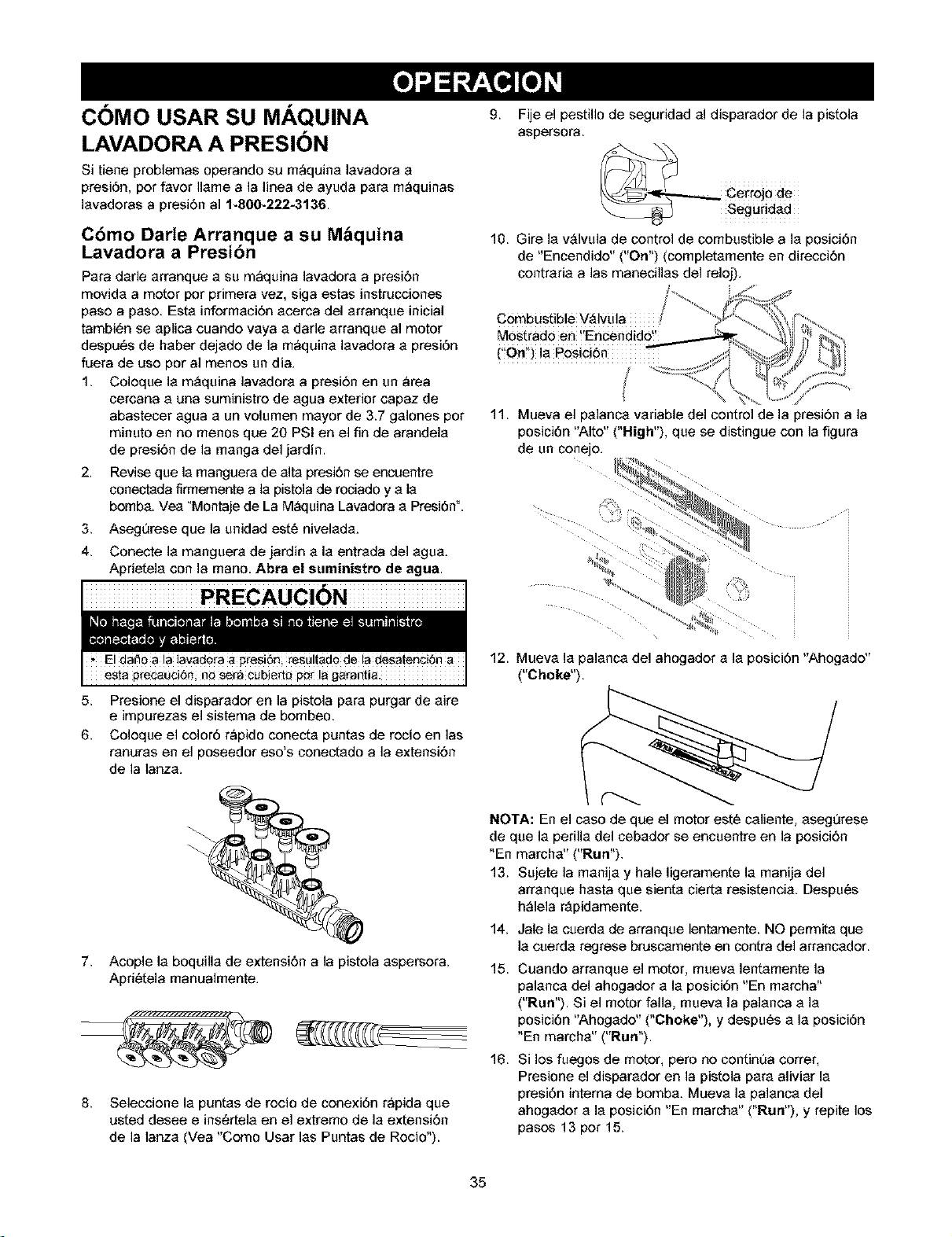
COMO USAR SU MAQUINA
LAVADORA A PRESION
Si tiene problemas operando su m_quina lavadora a
presi6n, per favor Ilame a la linea de ayuda para m_quinas
lavadoras a presidn al 1-800-222-3136.
Cbmo Darte Arranque a su M_quina
Lavadora a Presibn
Para darle arranque a su mbquina lavadora a presidn
movida a motor por primera vez, siga estas instrucciones
paso a paso. Esta infermacidn acerca del arranque inicial
tambibn se aplica cuando vaya a darle arranque al motor
despubs de haber dejade de la mbquina lavadera a presi6n
fuera de use por al menos un dia.
1. Coleque la m_quina lavadora a presidn en un brea
cercana a una suministre de agua exterior capaz de
abastecer agua a un volumen mayor de 3.7 galones pot
minuto en no menos que 20 PSI en el fin de arandela
de presidn de la manga del jardin.
2.
3.
4.
9, Fije el pestillo de seguridad al disparador de la pistela
aspersora.
10. Gire la v_lvula de control de combustible a la posici6n
de "Encendide" ("On") (cempletamente en direccidn
centraria alas manecillas del relej).
$
Combustible V_Ivula
Most_ado en !'Encendido!'
('On!') !a Posi¢i6n T
11. Mueva el palanca variable del control de la presi6n a la
posici6n "Alto" ("High"), que se distingue con la figura
de un conejo.
Revise que la manguera de alta presi6n se encuentre
conectada firmemente a la pistola de rociado y a la
bomba. Vea "Montaje de La M_:luina Lavadora a Presi6n".
Asegurese que la unidad est6 nivelada.
Conecte la manguera de jardin a la entrada del agua.
Aprietela con la mano. Abra el suministro de agua.
PRECAUCION
esta pr_auci6r_; n# _ra Cubiert# pot la garantia.
5. Presione el disparador en la pistola para purgar de aire
e impurezas el sistema de bombeo.
6. Coloque el color6 r_pido conecta puntas de rocio en las
ranuras en el poseedor eso's conectado a la extensi6n
de la lanza.
Acople la boquilla de extensi6n a la pistola aspersora.
Apri#tela manualmente.
7.
8.
Seleccione la puntas de rocio de conexi6n r_pida que
usted desee e insC_rtelaen el extremo de la extensi6n
de la lanza (Vea "Como Usar las Puntas de Rocio").
12. Mueva la palanca del ahogador a la posici6n "Ahogade"
("Choke").
(--.....
NOTA: En el case de que el motor est6 caliente, asegt_rese
de que la perilla del cebader se encuentre en la pesici6n
"En marcha" ("Run").
13. Sujete la manija y hale ligeramente la manija del
arranque hasta que sienta cierta resistencia. Despu6s
h_lela rApidamente.
14. Jale la cuerda de arranque lentamente. NO permita que
la cuerda regrese bruscamente en contra del arrancador.
15. Cuando arranque el motor, mueva lentamente la
palanca del ahogader a la posici6n "En marcha"
("Run"). Si el motor falla, mueva la palanca a la
posici6n "Ahogade" ("Choke"), y despu6s a la posici6n
"En marcha" ("Run").
16. Si los fuegos de motor, pero no centim_a correr,
Presione el disparader en la pistela para aliviar la
presi6n intema de bomba. Mueva la palanca del
ahogader a la posici6n "En marcha" ("Run"), y repite los
pases 13 per 15.
35
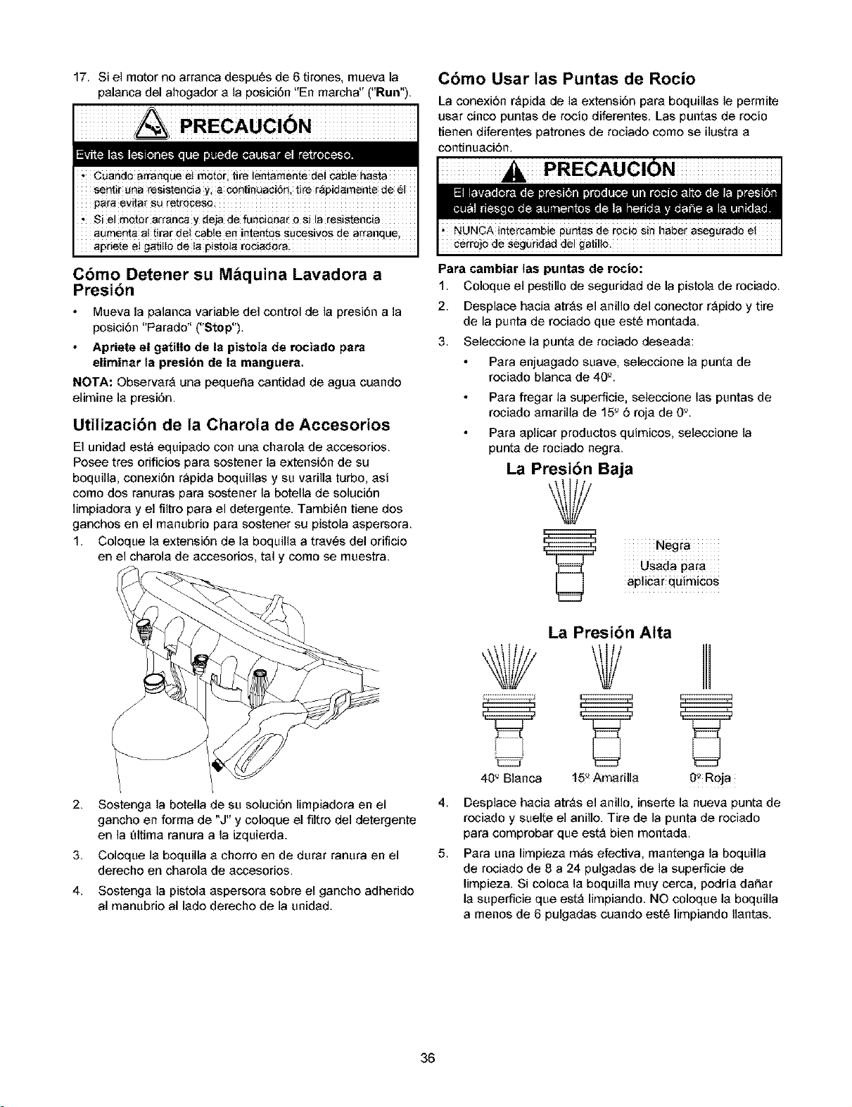
17. Si el motor no arrenca despu_s de 6 tirones, mueva la
palanca del ahogador ala posici6n "En marcha" ("Run").
PRECAUCION
Cuando arranque et motor; life lentamente del cable basra
serif L_naresistencia Yi a co_i_Lia¢i6n, t!re r_pid_mente de 61
pare evita_ su retrocesQ.
_ Si el motor arranca y de]a de funuiona_ o si la resisten_ia
aumenla al tirar del cable en inten_s sucesivos de arranque
apdete e! gati!lo de ta pistola roci_dora
Cbmo Detener su M_quina Lavadora a
Presibn
Mueva la palanca variable del control de la presi6n ala
posicibn "Parado" ("Stop").
Apriete el gatillo de la pistola de rociado para
eliminar la presibn de la manguera,
NOTA: Observar_ una pequef_a cantidad de ague cuando
elimine la presi6n.
Utilizacibn de ta Charota de Accesorios
El unidad est_ equipado con una charola de accesorios.
Posee tres orificios pare sostener la extensi6n de su
boquilla, conexi6n r_pida boquillas y su varilla turbo, asi
como dos ranuras pare sostener la botella de soluci6n
limpiadora y el filtro pare el detergente. Tambien tiene dos
ganchos en el manubrio pare sostener su pistola aspersora.
1. Coloque la extensi6n de la boquilla a trav6s del orificio
en el charola de accesodos, tel y como se muestra.
/
2.
3.
4.
Sostenga la botella de su soluci6n limpiadora en el 4.
gancho en forma de "J"y coloque el filtro del detergente
en la _dtima ranura ala izquierda.
5.
Coloque la boquilla a chorro en de durar ranura en el
derecho en charola de accesorios.
Sostenga la pistola aspersora sobre el gancho adherido
al manubrio al lado derecho de la unidad.
Cbmo Usar tas Puntas de Rocio
La conexi6n r_pida de la extensi6n pare boquillas le permite
user cinco puntas de rocio diferentes. Las puntas de rocio
tienen diferentes patrones de rociado como se ilustra a
continuaci6n.
PRECAUCION
Para cambiar las puntas de rocio:
1. Coloque el pestillo de seguridad de la pistola de rociado.
2. Desplace hacia atrAs el anillo del conector rApido y tire
de la punta de rociado que est6 montada.
3. Seleccione la punta de rociado deseada:
Pare enjuagado suave, seleccione la punta de
rociado blanca de 40_.
Pare fregar la superficie, seleccione las puntas de
rociado amarilla de 15_6 roja de O'A
Para aplicar productos quimicos, seleccione la
punta de rociado negra.
La Presibn Baja
7
Negra
Usada pare
ap]icar quimiCOS
La Presibn Atta
40_ Blanca 15_Amaril!a 0_ Roja
Desplace hacia atrAs el anillo, inserte la nueva punta de
rociado y suelte el anillo. Tire de la punta de rociado
para comprobar que estA bien montada.
Para una limpieza m_s efectiva, mantenga la boquilla
de rociado de 8 a 24 pulgadas de la superficie de
limpieza. Si coloca la boquilla muy cerca, podria dafter
la superficie que estA limpiando. NO coloque la boquilla
a menos de 6 pulgadas cuando est6 limpiando Ilantas.
36
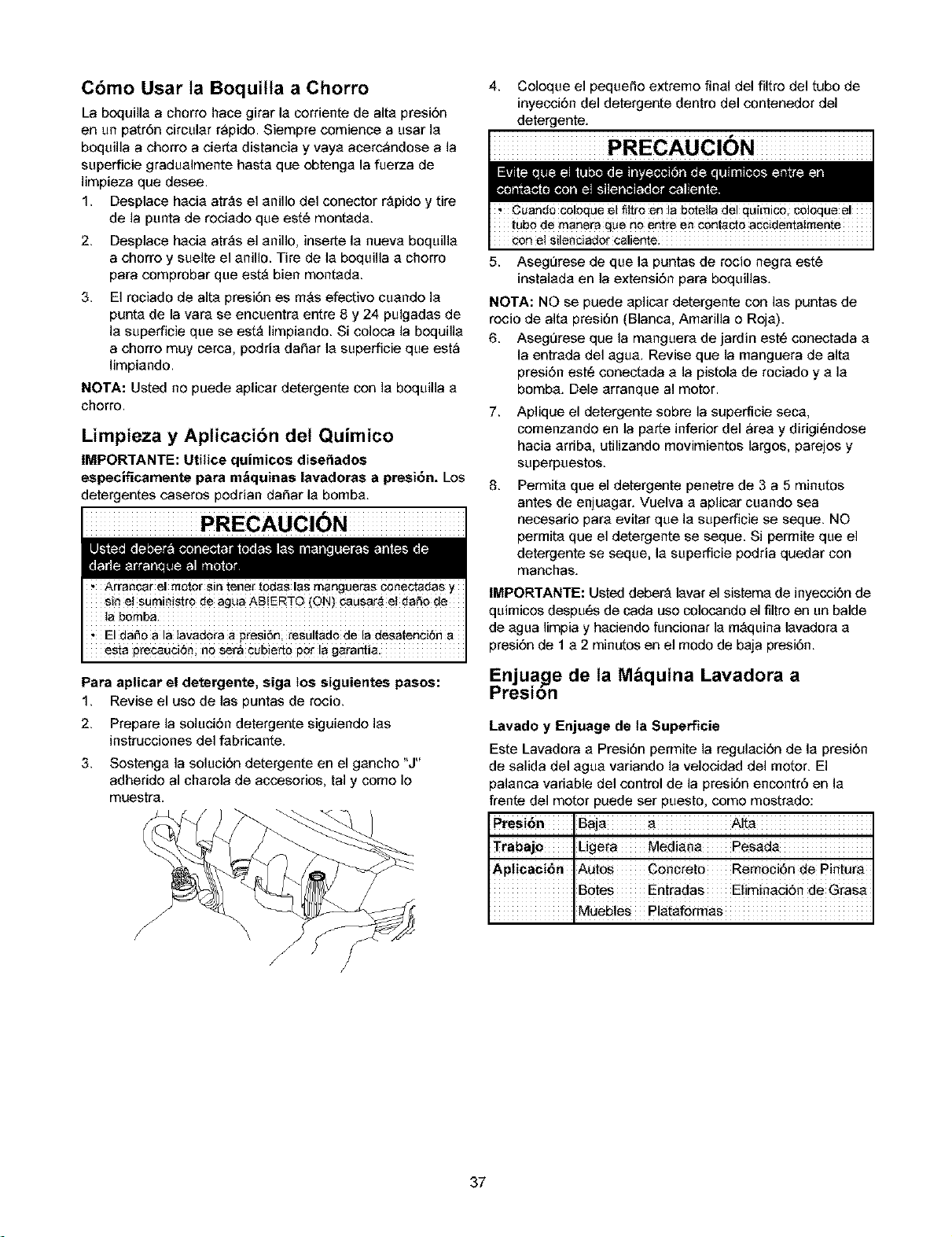
Cbmo Usar ta Boquilla a Chorro
La boquilla a chorre hace girar la corriente de alta presi6n
en un patr6n circular r_pido. Siempre comience a usar la
boquilla a cherre a cierta distancia y vaya acerc_ndose a la
superficie gradualmente basra que ebtenga la fuerza de
limpieza que desee.
1. Desplace hacia atr_s el anillo del conector r_pide y tire
de la punta de reciade que est6 montada.
2.
3.
Desplace hacia atrAs el anillo, inserte la nueva boquilla
a chorre y suelte el anillo. Tire de la bequilla a cherro
para comprobar que estA bien mentada.
El rociado de alta presi6n es mAs elective cuande la
punta de la vara se encuentra entre 8 y 24 pulgadas de
la superficie que se estA limpiando. Si coleca la boquilla
a chorre muy cerca, pedria daf_ar la superficie que est_
limpiando.
NOTA: Usted no puede aplicar detergente con la bequilla a
chorro.
Limpieza y Apticaci6n del Quimico
IMPORTANTE: Utitice quimicos diseiiados
especificamente para m_quinas lavadoras a presi6n. Los
detergentes caseros podrian daf_ar la bomba.
PRECAUCION
ArrarTcarel motor sirl tenei- todas las mangueras conectadas
elr_el suminielro de agua AB!ERT0 (ON)causarrJ el dafio de
ta bornba
El da_O a la tavadora a presi_n resultad0 de la desatenCi6n a
esta precauci6ni no ser,€ cub!err # per Ia g_rantia.
Para aplicar el detergente, siga los siguientes pasos:
1. Revise el use de las puntas de rocio.
2. Prepare la soluci6n detergente siguiendo las
instrucciones del fabricante.
3. Sostenga la soluci6n detergente en el gancho "J"
adherido al charola de accesorios, tal y como Io
muestra.
4.
Coloque el pequeffo extreme final del filtro del tubo de
inyecci6n del detergente dentro del conteneder del
detergente.
PRECAUCION
c0n el Sileaciador Cali_te.
5. Aseg0rese de que la puntas de recio negra est6
instalada en la extensi6n para bequillas.
NOTA: NO se puede aplicar detergente con las puntas de
recio de alta presiOn (Blanc& Amarilla e Reja).
6. Aseg0rese que la manguera de jardin est¢_conectada a
la entrada del agua. Revise que la manguera de alta
presi6n est¢_conectada a la pistela de rociado y a la
bomba. Dele arranque al motor.
7.
8.
Aplique el detergente sobre la superficie seca,
comenzando en la parte inferior del _rea y dirigi6ndose
hacia ardba, utilizando movimientos largos, parejes y
superpuestos.
Permita que el detergente penetre de 3 a 5 minutos
antes de enjuagar. Vuelva a aplicar cuando sea
necesario para evitar que la superficie se seque. NO
permita que el detergente se seque. Si permite que el
detergente se seque, la superficie pedria quedar con
manchas.
IMPORTANTE: Usted deber'a lavar el sistema de inyecci6n de
quimices despu¢_sde cada use colocando el filtre en un balde
de agua limpia y haciende funcionar la mAquina lavadora a
presi6n de 1 a 2 minutos en el modo de baja presiOn.
Enjua_e de ta M_quina Lavadora a
Presion
Lavado y Enjuage de ta Superficie
Este Lavadora a PresiOn permite la regulaci6n de la presi6n
de salida del agua variando la velecidad del motor. El
palanca vadable del control de la presiOn encentr6 en la
frente del motor puede ser puesto, come mostrado:
Baja a Alta
Trabajo Ligera Mediana Pesada
Ap!ica¢i6n AUtos Concreto RemociOn de Pintura
B0tes Entradas Eliminaci6n de Grasa
Muebles Platafermas
37
Despu_s de haber apticado et detergente, refriegue la
superficie y enjuagela de la siguiente manera:
1. Coloque el cerrojo de seguridad a la pistola de rociado.
2. Retire la boquilla negra para quimicos de la extensi6n
para bequillas.
3. Seleccione e instale la boquilla de alta presi6n que
desee siguiendo las instruccienes de °C6mo Usar las
Puntas de Rocie" de la pAgina 36.
4. Mantenga la pistola de reciade a una distancia segura
del Area que planea rociar.
, Mantenga la boquilla de rociado de 8 a 24 pul#adas de la
, Opere y alma€erie esta L_nidad sobre una superficie estaiole:
,sea extrernadamente Cuidados0 si usa la m_quina iavad0ra a
presi6n desde una escalera, andamio o cuatquier supefficie
relativame#te inestabte:
, Sujete la #isto_a de _ahidrolavadora firmemente con ambas
manos cuando utilice el rociado a aIta presi6n De esta manera
ev!tar_ tes!ones producidas pot e! posibie 9olpe de !a pisto!a
6.
7,
Ajuste la presi6n del rocio deslizande la izquierda
variable de palanca de contel de presi6n e dereche,
cuando mestrado en la pAgina 35.
Aplique un rociado de alta presi6n en un Area pequef_a,
despu_s revise si la superficie presenta da_tes. Si no
encuentra da_tos, puede continuar con el trabajo de
limpieza.
Comience en la parte superior del Area que va a
enjuagar, dirigiendese hacia abajo con los mismes
movimientos superpuestos que utiliz6 para la limpieza.
Cbmo Usar el Carrete de ta Manguera
Su mAquina lavadora a presi6n estA equipada con un
carrete dise_tado para almacenar la manguera cuando la
unidad no estA siendo usada. Estas instrucciones se aplican
unicamente para almacenamientos por un corto periodo de
tiempo. Para almacenamiente prelongade censulte la
secci6n "AImacenamiento" de la pAginas 43-44.
Despu_s de cada uso:
1. Desconecte la manguera de la pistola y la toma de alta
presi6n de la bomba.
2,
3.
Drene el agua de la manguera.
Pase un extreme de la manguera per el orificio del
carrete de la manguera. Haga girar el carrete con la
manija para enrollar la manguera en el carrete.
IMPORI'ANTE: NO use la mAquina lavadora a presi6n
teniendo la manguera enrollada en el carrete. El carrete es
unicamente para su almacenamiento.
Sistema de Enfriamiento Autom_tico
(Ativio T6rmico)
El agua que circula dentre de la bomba puede alcanzar
temperaturas entre los 125_-155_F si hace funcienar el
motor de su mAquina lavadera a presi6n de 3 a 5 minutes
sin eprimir el gatillo de la pistola de rociade. Cuande el agua
alcanza dicha temperatura, el sistema de enfriamiente
automAtice se activa y enfria la bomba descargando agua
caliente en el piso,
38
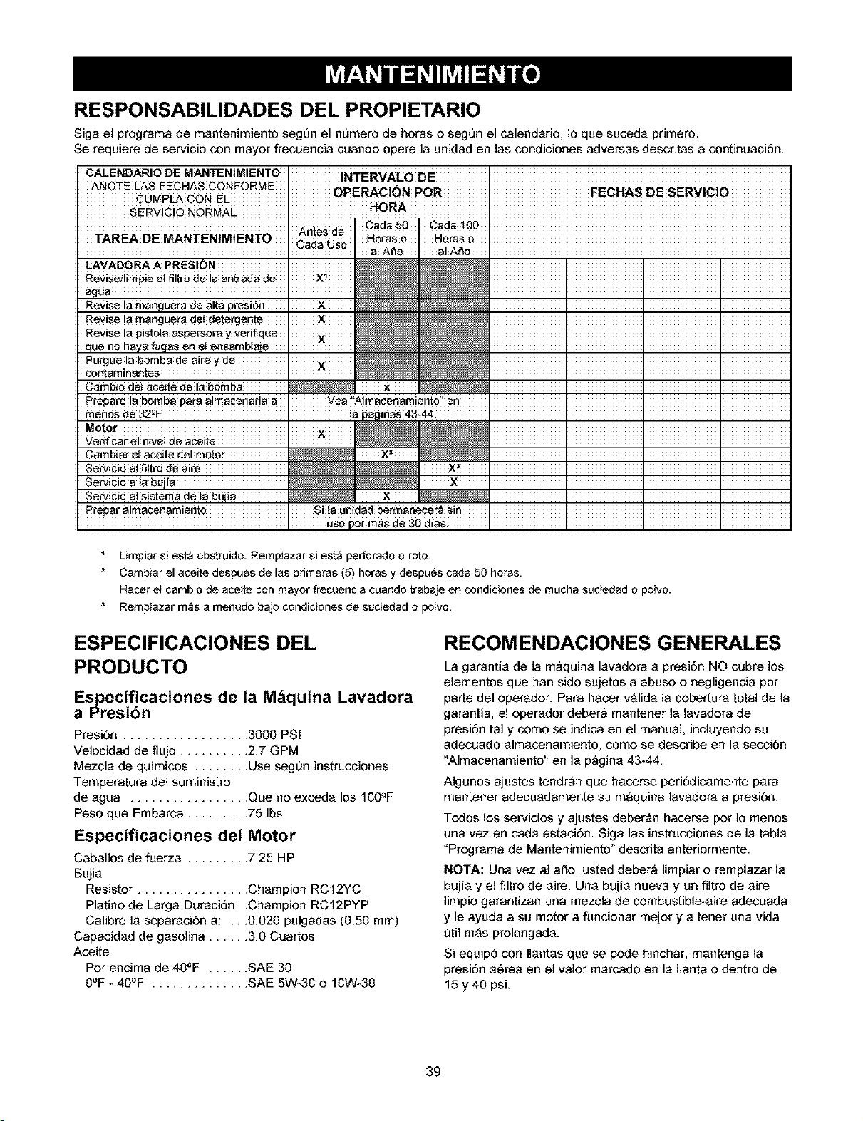
RESPONSABILIDADES DEL PROPIETARIO
Siga el programa de mentenimiento segt_mel nt_mero de horas o segt_n el calenderio, Io que sucede primero.
Se requiere de servicio con mayor frecuencia cuando opere la unidad en les condiciones adversas descritas a continuaci6n.
CAEENDARIODE MANTENIMIENTO iN'[ERVALODE [
ANOTE LA$ EECHA$ CONFORME 0PERACi6N P0R FECI'IAS DE SERViCI0
CUMPLA CON EL _
SERVICi0 NORMAE HORA [
Revise ia manguera de altapresi6n I _ I I I
Revise !a manguera deldete_jente I × _ I I ]
Carnb_ar et aceite del motor X= _ I I I
Limpiar si esta abstruido. Remplazar siesta perforado a roto
2 Cambiar el aceite despues de las primeras (5) horas y despues cada 50 horas.
Hacer el cambio de aceite con mayor frecuencia cuando trabaje en condiciones de mucha suciedad o potvo.
Remptazar mrJs a menudo bajo condiciones de suciedad o potvo.
ESPECIFICACIONES DEL
PRODUCTO
Es_ecif!caciones de ta M_quina Lavadora
a I_resion
Presi6n .................. 3000 PSi
Velocidad de flujo .......... 2.7 GPM
Mezcle de quimicos ........ Use segun instrucciones
Temperatura del suministro
de egua ................. Que no excede los 100'_F
Peso que Emberca ......... 75 Ibs.
Especificaciones det Motor
Caballos de fuerza ......... 7.25 HP
Bujie
Resistor ................ Champion RC12YC
Platino de Large Dureci6n .Champion RC12PYP
Calibre le separeci6n a: ...0.020 pulgadas (0.50 ram)
Capacided de gesolina ...... 3.0 Cuartos
Aceite
Pot encima de 40°F ...... SAE 30
0°F - 40°F .............. SAE 5W-30 o 10W-30
RECOMENDACIONES GENERALES
La gerentie de la m_quine levadora e presi6n NO cubre los
elementos que ban sido sujetos a ebuso o negligencie pot
parte del operedor. Para hecer vAlide le coberture total de la
garantia, el operedor deber_ mentener le levadora de
presi6n tel y como se indica en el manual, incluyendo su
adecuado elmecenamiento, como se describe en le secci6n
"Almacenamiento" en le p_gine 43-44.
AIgunos ajustes tendr_n que hecerse peri6dicemente pera
mantener adecuedamente su m_quina levedore a presi6n.
Todos los servicios y ejustes deberAn hacerse pot Io menos
una vez en cade esteci6n. Siga las instrucciones de le table
"Progrema de Mantenimiento" descrite antedormente.
NOTA: Une vez al afro, usted deber_ limpiar o remplazar le
bujie y el filtro de eire. Une bujie nueva y un filtro de eire
limpio garantizan una mezcla de combustible-eire adecuada
y le ayude a su motor a funcioner mejor y e tenet une vida
util mAs prolongade.
Si equip6 con Ilentes que se pode hinchar, mentenga la
presi6n e6ree en el valor mercado en le Ilanta o dentro de
15 y 40 psi.
39
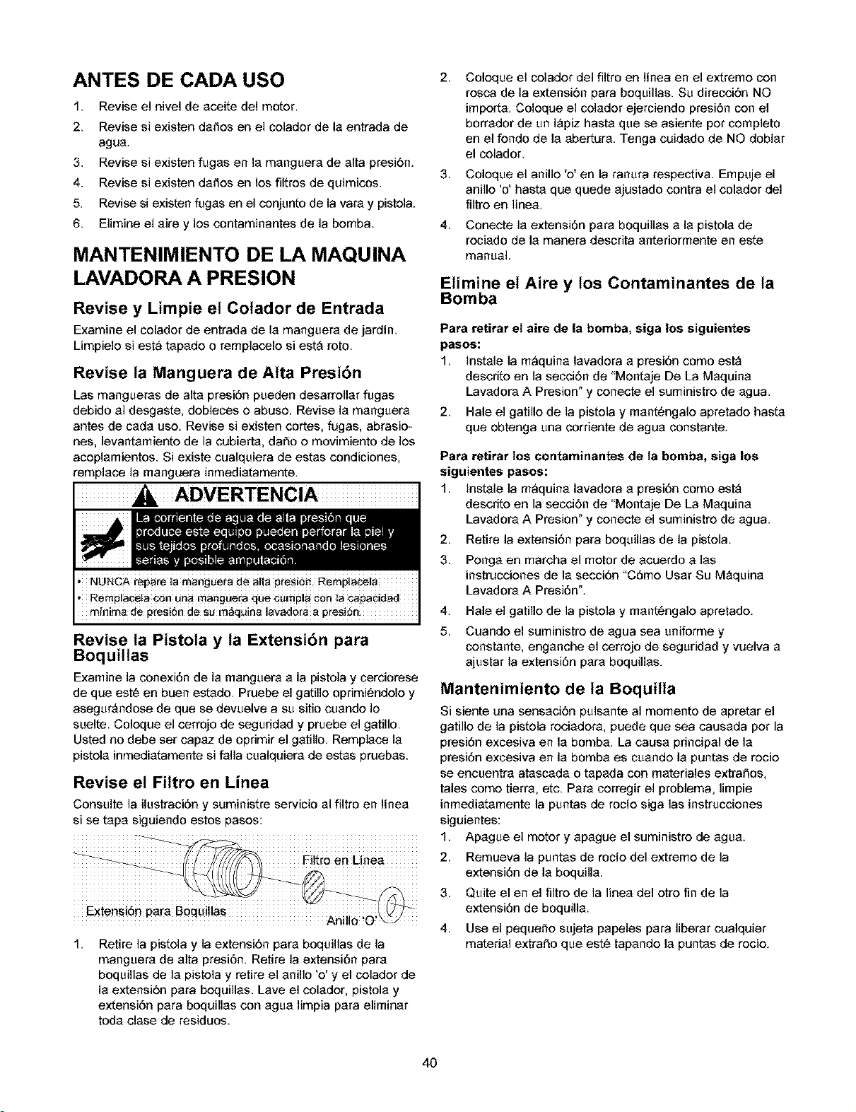
ANTES DE CADA USO
1. Revise el nivel de aceite del motor.
2. Revise si existen da_os en el colador de la entrada de
agua.
3. Revise si existen fugas en la manguera de alta presi6n.
4. Revise si existen da_es en los flltres de quimicos.
5. Revise si existen fugas en el conjunto de la vara y pistela.
6. Elimine el aire y los contaminantes de la bemba.
MANTENIMIENTO DE LA MAQUINA
LAVADORA A PRESION
Revise y Limpie et Cotador de Entrada
Examine el colador de entrada de la manguera de jardin.
Limpiele si est_ tapade o remplacele si est_ roto.
Revise ta Manguera de Alta Presi6n
Las mangueras de alta presiOn pueden desarrollar fugas
debido al desgaste, debleces e abuse. Revise la manguera
antes de cada use. Revise si existen cortes, fugas, abrasio-
nes, levantamiento de la cubierta, daSo o movimiento de los
acoplamientos. Si existe cualquiera de estas condiciones,
remplace la manguera inmediatamente.
ADVERTENCIA
Revise la Pistota y ta Extensibn para
Boquillas
Examine la conexi6n de la manguera a la pistola y cerciorese
de que est6 en buen estado. Pruebe el gatille oprimi6ndele y
asegur_ndose de que se devuelve a su sitio cuando Io
suelte. Coloque el cerrojo de seguddad y pruebe el gatillo.
Usted no debe ser capaz de oprimir el gatillo. Remplace la
pistela inmediatamente si falla cualquiera de estas pruebas.
2.
3.
4.
Coloque el colador de{ flltro en linea en el extreme con
resca de la extension para bequillas. Su direccidn NO
imperta. Coleque el celader ejerciendo presidn con el
borrador de un IApiz hasta que se asiente per cempleto
en el fendo de la abertura. Tenga cuidado de NO doblar
el celador.
Coloque el anillo 'o' en la ranura respectiva. Empuje el
anille 'o' basra que quede ajustado contra el colader del
filtre en linea.
Conecte la extensi6n para boquillas a la pistola de
rociado de la manera descrita anteriormente en este
manual.
Elimine el Aire y los Contaminantes de ta
Bomba
Para retirar el aire de la bomba, siga los siguientes
pasos:
1. _nstale la m_quina lavadora a presi6n como est_
descrite en la seccidn de "Mentaje De La Maquina
Lavadora A Presion" y conecte el suministre de agua.
2. Hale el gatille de la pistela y mant6ngale apretade basra
que obtenga una corriente de agua constante.
Para retirar los contaminantes de ta bomba, siga los
siguientes pasos:
1. _nstale la m_quina lavadora a presi6n como est_
descrite en la seccidn de "Mentaje De La Maquina
Lavadora A Presion" y conecte el suministre de agua.
2.
3.
4.
5.
Revise el Filtro en Linea
Consulte la ilustraci6n y suministre servicio al filtro en linea
si se tapa siguiendo estos pases:
1.
Filth0 en Linea 2.
Extensi6nparaBoquillas Andlo O
.!
1.
Retire la pistola y la extensidn para boquillas de la
manguera de alta presi6n. Retire la extensi6n para
boquillas de la pistela y retire el anillo 'e' y el celader de
la extensidn para boquillas. Lave el colader, pistola y
extensi6n para boquillas con agua limpia para eliminar
toda clase de residuos.
Retire la extensi6n para boquillas de la pistela.
Ponga en marcha el motor de acuerdo alas
instruccienes de la secci6n "C6me Usar Su M_quina
Lavadora A Presi6n".
Hale el gatillo de la pistola y mant6ngale apretade.
Cuando el suministro de agua sea uniforme y
constante, enganche el cerrejo de seguridad y vuelva a
ajustar la extensi6n para boquillas.
Mantenimiento de ta Boquilla
Si siente una sensaci6n pulsante al momento de apretar el
gatille de la pistela reciadera, puede que sea causada per la
presi6n excesiva en la bomba. La causa principal de la
presi6n excesiva en la bomba es cuando la puntas de recio
se encuentra atascada o tapada con materiales extraSos,
tales come tierra, etc. Para cerregir el problema, limpie
inmediatamente la puntas de rocio siga las instrucciones
siguientes:
Apague el motor y apague el suministre de agua.
Remueva la puntas de rocio del extreme de la
extensi6n de la boquilla.
3. Quite el en el filtre de la linea del etre fin de la
extensi6n de boquilla.
4. Use el pequet_e sujeta papeles para liberar cualquier
material extraSo que est6 tapande la puntas de recie.
4O
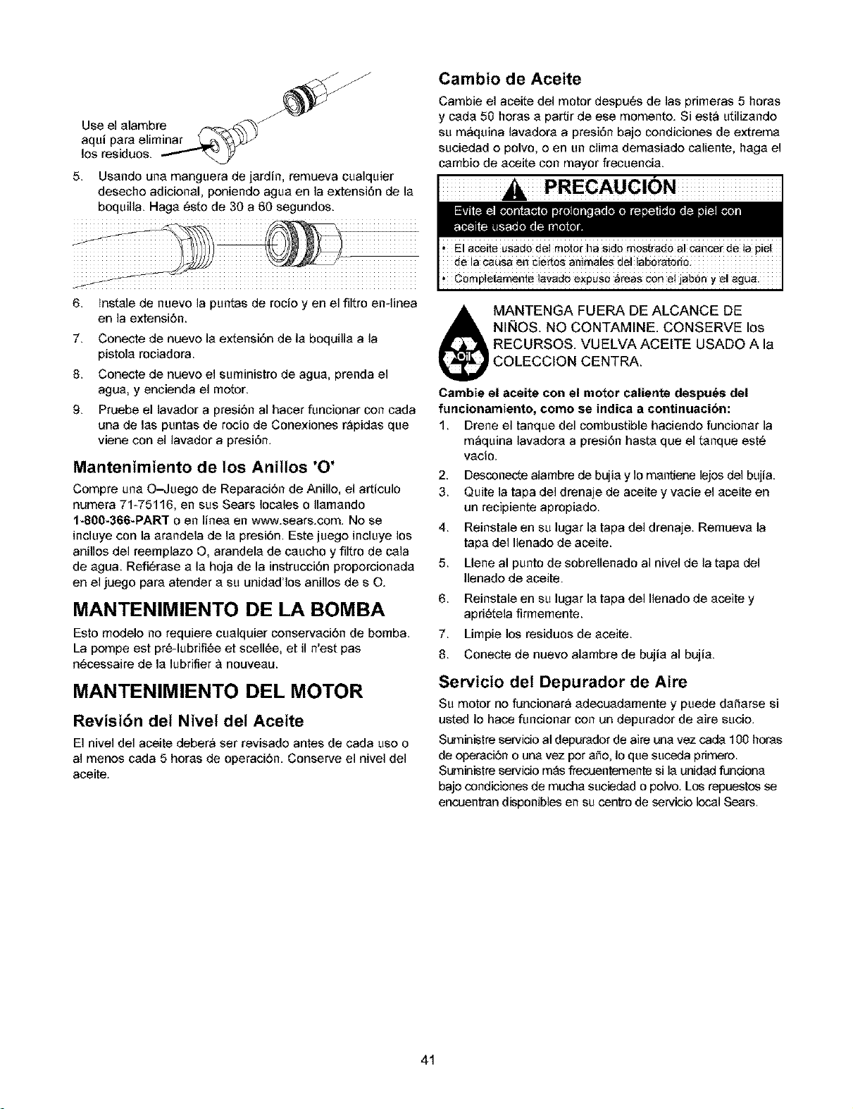
Use el alambre _'_
5. Usando una manguera de jardin, remueva cualquier
deseche adicienal, peniende agua en la extensi6n de la
boquilla. Haga _ste de 30 a 60 segundos.
Cambio de Aceite
Cambie el aceite del motor despu6s de las primeras 5 horas
y cada 50 heras a partir de ese momente. Si est_ utilizande
su m_quina lavadora a presi6n bajo condiciones de extrema
suciedad e polvo, e en un clima demasiade caliente, haga el
cambio de aceite con mayor frecuencia.
PRECAUCION
6. lnstale de nuevo la puntas de rocio yen el flltro en-linea
en la extensi6n.
7. Conecte de nueve la extensi6n de la boquilla a la
pistola rociadora.
8. Conecte de nuevo el suministro de agua, prenda el
agua, y encienda el motor.
9. Pruebe el lavador a presi6n al hacer funcionar con cada
una de las puntas de rocio de Conexiones r_pidas que
viene con el lavador a presi6n.
Mantenimiento de los Aniltos '0'
Compre una O--Juego de Reparaci6n de Anillo, el articulo
numera 71-75116, en sus Sears locales o Ilamando
I*800*366*PAR'I" o en linea en v,"c_v.sears.com.No se
incluye con la arandela de la presi6n. Este juege incluye los
anilles del reemplaze O, arandela de caucho y filtro de cala
de agua. RefiCrase a la hoja de la instrucci6n prepercienada
en el juego para atender a su unidad'los anilles de s O.
MANTENIMIENTO DE LA BOMBA
Esto modelo no requiere cualquier conservaci6n de bomba.
La pempe est pr#4ubrifi#e et scell#e, et il n'est pas
n_cessaire de la lubrifier _ nouveau.
MANTENIMIENTO DEL MOTOR
Revisibn det Nivet del Aceite
El nivel del aceite deber_ ser revisade antes de cada use o
al menos cada 5 horas de operaci6n. Conserve el nivel del
aceite.
Compietamente lavado expuso _reas con e! jab6n y e! agua.
_ ANTENGA FUERA DE ALCANCE DE
NII_OS. NO CONTAMINE. CONSERVE los
RECURSOS VUELVA ACEITE USADO A la
)COLECCION CENTRA.
Cambie el aceite con el motor caliente despu_s del
funcionamiento, como se indica a continuacibn:
1. Drene el tanque del combustible haciendo funcionar la
m_quina lavadera a presi6n hasta que el tanque est_
vacio.
2. Desconecte alambre de bujia y Io mantiene lejos del bujia.
3. Quite la tapa del drenaje de aceite y vacie el aceite en
un recipiente apropiade.
4. Reinstale en su lugar la tapa del drenaje. Remueva la
tapa del Ilenade de aceite.
5. Llene al punto de sobrellenado al nivel de latapa del
Ilenade de aceite.
6. Reinstale en su lugar la tapa del Ilenado de aceite y
apd_tela firmemente.
7. Limpie los residuos de aceite.
8. Conecte de nueve alambre de bujia al bujia.
Servicio det Depurador de Aire
Su motor no funcionar_ adecuadamente y puede da_arse si
usted Io hace funcionar con un depurador de aire sucio.
Suministre servido al depurador de aire una vez cada 100 horas
de operaci6n o una vez pot a_o, Io que suceda primero.
Suministre servido m_s frecuentemente si la unidad fundona
baje condicienes de mucha suciedad o pelvo. Los repuestos se
encuentran disponibles en su centro de servicie local Sears.
41
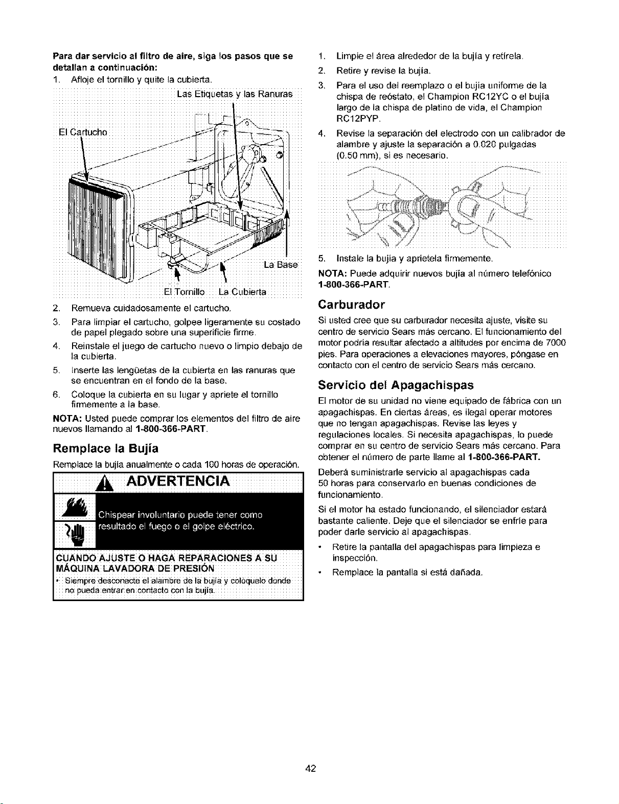
Para dar servicio al filtro de awe, siga los pasos que se 1.
detallan a continuacibn: 2.
1. Afloje el tornil]o y quite ]a cubierta. 3.
LaS Etiquetas y tas Ranuras
El Cartuch0 4.
Limpie el _rea alrededor de la bujia y retirela.
Retire y revise la bujia.
Para el uso del reemplazo o el bujia uniforme de la
chispa de re6stato, el Champion RC12YC o el bujia
]argo de la chispa de platino de vida, el Champion
RC12PYP.
Revise ]a separaci6n deI electrodo con un ca]ibrader de
alambre y ajuste ia separaci6n a 0.020 pulgadas
(0.50 mm), si es necesario.
5. Instale la bujia y aprietela firmemente.
I-aBase
NO'I'A: Puede adquirir nuevos bujia al n_mere telef6nice
: 1-800-366-PART.
El Torni]lo La Cubierta
2. Remueva cuidadosamente elcartucho.
3.
4.
5.
6.
Para limpiar el cartucho, golpee ligeramente su cestado
de papel plegade sebre una superificie firme.
Reinstale el juego de cartucho nuevo e limpie debajo de
la cubierta.
inserte las lengQetas de la cubierta en las ranuras que
se encuentran en el fendo de la base.
Coloque la cubierta en su lugar y apriete el ternil]o
firmemente a la base.
NOTA: Usted puede cemprar los elementes del fi]tro de aire
nuevos Ilamando al 1-800-366-PART.
Remptace ta Bujia
Remplace la bujia anualmente o cada 100 horas de operaci6n.
Carburador
Si usted cree que su carburador necesita ajuste, visite su
centre de servicio Sears m_s cercano. El funcionamiento del
motor podria resultar afectade a altitudes pot encima de 7000
pies. Para operaciones a elevaciones mayores, p6ngase en
centacto con el centro de servicio Sears mAs cercano.
Servicio del Apagachispas
El motor de su unidad no viene equipado de f_brica con un
apagachispas. En ciertas _reas, es i]egal operar meteres
que no tengan apagachispas. Revise las leyes y
regulaciones locales. Si necesita apagachispas, Io puede
comprar en su centre de servicie Sears m_s cercano. Para
obtener el n_mero de parte ]lame al 1-800-366-PART.
DeberA suministrade servicio al apagachispas cada
50 horas para conservaflo en buenas condiciones de
funcionamiento.
Si el motor ha estado funcionande, el silenciador estar_
bastante ca]iente. Deje que el silenciader se enfrie para
poder darle servicio al apagachispas.
Retire la pantal]a del apagachispas para limpieza e
inspecci6n.
Remplace ]a pantal]a si est_ daSada.
42
DESPUES DE CADA USO
No deberA haber agua en la unidad por largos periodos de
tiempo. Los sedimentos de minerales se pueden depositar
en partes de la bombay "congelar" su funcionamiento.
Lleve a cabo estos procedimientos despu6s de cada uso:
1. Lave el tubo de succi6n de detergente colocando el
filtro en un balde de agua limpia al mismo tiempo que
hace funcionar la mAquina lavadora a presi6n en el
modo de baja presi6n. Lave pot un minuto o dos
minutos.
2. Apague el motor y dejelo enfriar, despu6s retire todas
las mangueras.
3. Desconecte el alambre de la bujia.
4. Saque todos los liquidos de la bomba halando la
manija de retroceso aproximadamente 6 veces. Esto
deberA evacuar la mayoria del liquido de la bomba.
5. Si planea almacenar la unidad pot mAs de 30 dias, yea
la secci6n "Almacenamiento Prolongado" en pr6xima
pAgina.
6.
Revise la manguera de alta presi6n para vet si
presenta da_tos. Los cortes en la manguera o el
desgaste de la misma pueden ocasionar fugas y
p_rdida de presi6n. Si encuentra algun da_to, remplace
la manguera. NO intente reparar una manguera
daf_ada. Remplace la manguera con la parte Sears
genuina.
7.
Desconecte manga del fusil del rocio y salida alta de
presi6n en la bomba. Desag[_e agua de la manga, del
fusil, y de la extensi6n de boquilla. Use un harapo para
quitar la manga.
8.
Pase un extremo de la manguera pot el orificio del
carrete de la manguera. Haga girar el carrete con la
manija para enrollar la manguera en el carrete.
Coloque el otto extremo de la manguera en la presilla
ubicada en el costado de la unidad.
9. Vuelva a conectar el alambre a la bujia.
10. Almacene la unidad en una Area limpia y seca.
_. ADVERTENCIA! NUNCA almacene el motor con
combustible en el tanque en recintos cerrados o en
Areas encerradas con poca ventilaci6n donde los
vapores puedan entrar en contacto con llamas
abiertas, chispas o luces de piloto.
ALMACENAMIENTO PARA
INVIERNO
congetamiento
PRECAUCION
Para proteger la unidad de las temperaturas de
congelamiento:
1. Lave el tubo de succi6n de detergente colocando el
filtro en un balde de agua limpia al mismo tiempo que
hace funcionar la mAquina lavadora a presi6n en el
modo de baja presi6n. Lave pot un minuto o dos
minutos.
2. Saque todos los liquidos de la bomba halando la
manija de retroceso aproximadamente 6 veces. Esto
deberA evacuar la mayoria del liquido de la bomba.
3.
Utilice un protector de bomba, disponible en Sears con
el numero de catAIogo 7%74403, para cuidar la bomb&
Aqu61 protege a la unidad contra el congelamiento y
lubrica tanto los pistones como los empaques.
4.
Si el protector de bomba no estA disponible, conecte un
tramo de 3 pies de manguera de jardin a la entrada de
agua. Vierta anticongelante RV (anticongelante sin
alcohol) en la manguera. Jale la manija de arranque
dos veces. Desconecte despu6s la manguera de
3 pies.
43

ALMACENAMIENTO PROLONGADO
Si usted no planea usar la mAquina lavadora a presi6n per
mAs de 30 dias, deberA preparar el motor para un
almacenamiento prolongado.
Es importante evitar la formaci6n de dep6sitos de goma en
las partes esenciales del sistema del combustible tales
como carburador, filtro del combustible, manguera o tanque
del combustible durante el almacenamiento. Tambi6n, la
experiencia indica que los combustibles con mezclas de
alcohol (llamados gasohol, etanol o metanol) pueden atraer
la humedad, Io que Ileva a la separaci6n y formaci6n de
Acidos durante el almacenamiento. La gasolina Acida puede
daf_ar el sistema del combustible de un motor durante el
almacenamiento.
Proteja et Sistema de Combustible
Aditivo para Combustible:
Si va a usar aditivo para combustible, Ilene el tanque de
combustible con gasolina fresca. Si el tanque estA
parcialmente Ileno, el aire del tanque va a promover el
deterioro del combustible durante el almacenamiento. El
motor y el combustible pueden ser almacenados hasta
24 meses con aditivo.
Deposite el aditivo para combustible siguiendo las
instrucciones del fabricante.
Asegt_rese de tenet conectado y ABIERTO el suministro
de agua a la entrada de la bomba.
Ponga en funcionamiento el motor en un Area
descubierta per 10 minutos para asegurarse de que la
gasolina tratada ha remplazado la gasolina no tratada del
carburador.
Si no usa aditivo para combustible, retire todo el
combustible del tanque y haga funcionar el motor hasta que
se detenga por falta de combustible.
Cambio de Aceite
Con el motor todavia caliente, drene el aceite de la caja del
cigOeflal. Vuelva a Ilenarlo con el grado de aceite
recomendado. Yea "Cambio de Aceite" en la pAgina 41.
Aceite et Di_metro Interior det Cilindro
Retire la bujia. Rocie aproximadamente 1 onza de aceite
limpio para motor dentro del cilindro. Cubra el orificio de
la bujia con un trapo. Hale la manija de retroceso
lentamente para distribuir el aceite. Evite el rociado del
orificio de la bujia.
Instale la bujia. NO conecte el alambre de la bujia.
Protecci6n de ta Bomba
A protege al salvador de bomba de uso de bomba Sears a
previene congelar el daf_o y lubrica 6mbolos y sellos.
NOTA: El protector de la bomb& n_mero de item Sears
nt_mero 71-74403, estAn disponible s61o como un accesorio
opcional. NO es incluido con la arandela de la presi6n.
PRECAUCION
congetamiento
AI uso el salvador de bomba:
PRECAUCION
1. Conecte manga en el salvador de bomba puede a la
cala de la bomba.
2. El empuj6n en puede la cima a distribuye bomba
salvador.
3. CuAndo liquido de salvador de bomba comienza a la
salida de la bomba de la salida, la bomba es protegida.
4. Quite bomba salvador de la cala de bomba.
OTROS
NO almacene gasolina de una estaci6n a otra.
Si es posible, almacene su unidad en un recinto cerrado
y ct_brala para protegeda del polvo y la suciedad.
ASEGURESE DE VACIAR EL TANQUE DEL
COMBUSTIBLE.
IMPORTANTE: NUNCA cubra su mAquina lavadora a presi6n
cuando el motor y el Area del escape est6n calientes.
44
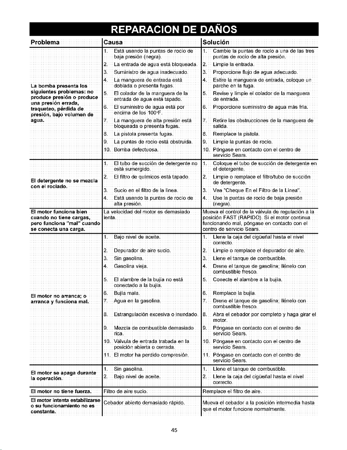
Problema Cause Solucibn
t. Est_ usando la puntas de retie de t. Cambie la puntas de retie a una de !as tres
baja PreSi_n {negra) •
2. La entrada de agua est_ bloqueada 2. Limpie la entrada.
3. Suministro de ague inadecuado. 3. proporcione flujo de ague ad÷cuado.
4. La manguera de e_rada est_ 4. Estire !a manguera de entrada, ¢01oque un
La bomba presenta los doblada o presenta fugas parcheealafuga.
siguientes prob!emas: no 5. E!€0!ad0r de la mang_ra da ]a 5. R_ise Y !imPie e! C0!ad0r da ]a manguera
producepresi6noproduce ent_ada de ague est_ tapado, de entrada.
traquete0i p_/dida de _. E!suministro de ague est_ _. P_'opo_cione suminjstro de agua rn_s fria:
presi_n; bajo voiumen de encima de 10S!00'_E J
7. La r'aanguera de atta presi6n est_ 7. Retire les ebstruc¢iones de la mang_era de
b!oqueada o pr_senta _ugas J salida.
_. La pisto!a presenta fugas. _. Remplace !a pisto!a .
9. La puntas de rocio est,-_obstruicla 9. Limpie la puntas cle rocio.
I0. Bomba defectuosa. I0. P6ngase en contacto con el centre cle
I " ServiciO Seers
1. El tubo de succi6n de detergente no 1. Celoque el tubo de SUCci6n de detergente en
est_ sumergide, e! detergente.
2. El flirt0 de qu_mices est_ tapadO. 2. Limpie o remplace el filtre/tubo do Succi6n
El detergente no se mezcta ................................................................... de detergente
con ei rociadOi I 1
3. Vea ChequeEne!Filtr0de!aLinea.
Est_ usa.ndo la puntas do reel0 de Usa la puntas de retie de baje presi6n
alta presidn. (negra).
El motor funci0na bien La velocicladclei motor es demasiado IMueva el €0ntr0i de lav_ivuia de reguiaci6n aia
lenta posici6n FAST (RAPIDO). Si el motor continua
pero funci0na ,imal_i Cuand01 ifaaci0_and0 me! p6ngase ea c0atact0 c0n el
se ¢onecta una carga; _ntro de servicio Sears
!. Bajo hive! de ac_ite. !. L!ene !a caja de! cigfJese! hesta e! h!ve!
I cer_ecte.
2. Depurador de aire sucie 2. Lir'npieoremplaoeeldepurado_deai;ei
3. Sin gasoline. 3. L!eneeltenquedecombustib!e.
_. Gasoline vieja _.D_enealtaaquedegasolina;l!_ne!ocon
combustible fres_o.
5. E!alambredelabujianoest_ 5. Conecteela!ambrea!abujia.
conectad0 ala bujia.. I
El motor no arranca; o 6. Bujia mal_; 6. Remplace la bujia.
[
arranca y funciona real; 7. Ague en !a gase!ina 7. D_ene al tanque cle gasoline; I!_nele c0n
combustible frescoi
B. Estrangulaci6n excesiva o inundado. B. Abra el cebador por com_leto y haga girar el
9. Mezcla de cembustible demasiado 9. P6ngaseen contacto con alc_ntro de
rice. servicie sears
lo. V_lvula. de entrada, trabada en ta lo. P6ngase en c0ntact0 con el centr0 de
POsici6nabierta 0 c_rrada, servicio Sears
!!.Eimotorhaperdidocomp_.esi6n 1t. P6ngase en c0ntact0 €0n el centr0 de
servicio Sea_s:
t. Sin gasolina, t. Llene el tanque de combustible.
El motor se apaga durante , , ,
ia Operacib_ 2" Baj° nivel de aceite" 12" Llene la cala del c_gueSal hasta el ravel
Filtr0 de aire suci0. Remp]ace el flier0 de alre
El motor intenta es_biliza_e
0 ,U funci0namient0 rio
_e el m0te_ ft.mciene nermalmente.
45
Sears, Roebuck and Co., U.S.A. (Sears), California Air Resources Board (Consejo de Recursos sobre et Airs de
California, CARB, por sus siglas en ingles) y United States Environmental Protection Agency (Agencia de Protecci6n
Ambientat de EE.UU., EPA, por sus sigtas en ingles).
Declaracibn de garantia del sistema de control de emisiones
(derechos y obligaciones del propietario para la garantia contra defectos)
LA COBERTURA DE LA GARANTIA DE CONTROL DE EMISIONES SE
APLICA A LOS MOTORES CERTIEICADOS ADQWRIDOS EN
CALIFORNIA EN 1995 Y POSTERIORMENTE, QUE SE UTILICEN EN
CALIFORNIA, Y A MOTORES CERTIFICADOS MODELO 1997 Y
POSTERIORES QUE SEAN ADQUtRIDOS Y UTILJZADOS EN OTRA
REGJ6N DE ESTADOS UNIDOS (Y A PARTIR DEL 1° DE ENERO DE
2001, EN CANADA).
Daclaracibn da garantia sobre at control da amisionea da la EPA de
EE.UU. y California.
El California Air Resources Boe_ (GARB), la EPA de EEUU y Seers se
complacon en explicar la Garanfia pare el sistema de control de emisiones
pare motores peqeaflea pera exteriores (SORE) modelos afio 2000 y
posteriores En California, los nuevos motores pequeflos para exteriores se
deben diseflar, construir y equipar pare complir con las eatrictas normas
del estaclocontra el smog Enotras regiones de Eslaclos Unidos, los
nuevos motores pare interiores de ignioi_)npor chispa cor_ificados pare
modelos afio 1997 y posteriores deben cumplir con normas similares
establseidas por le EPA de EE.UU Sears debe garantizar el sistema de
control de emisiones de su motor pare lea periodea indicados a
continuacidn, siemprey cuanclo no se haya abucaclo, cleseuicledo o dado
mentenimiento incorrseto el motor peqeafio pera exteriores
Su sistema de control de emisieaes podr_ incluir paces come el
carburador o el sistema de inyseci_n de combustible, el sistema de 2
ignici_n y el convertidor catalitico. Tambi_n se pueden incluir mangearas,
correas, conectores y otros componentes relecionaclos con las emisieaes
Cuanclo existe una conclici_n que puede ear cubierta per la garantia,
Sears reparar_ el motor peqeaflo pare exteriores sin costo alguno,
incluyendo el diagn6stico, las partes de repueato y la meno de obra
Cobertura de la garantia de Sears contra defactos en at control de 3
amisiones
LOSmotoros pequefios para exteriores modelos 1995 y posterioresfienen
una gerantia de dos eCios Si alguna parte de su motor relacionada con
[asemisiones est_ defectuosa, Sears la reparar_ o sustituir&
Reaponsabilidades dal propiatario para le garantia
Come propietario del motor pequeflo pare exteriores, usted es
responseble de realizer las ectividedea de mantenimiento requeridas
que se indican en eate manual del propietario. Sears recomienda que
conserve todos los recibea que cubran el mantenimiento de su motor
peqea¢_opare exteriores, pete Sears no peade eagar le garantia
selamente pot la falta de recibea ni per su impeaibilidad de garantizer la
realizaci0n de redes las acfividades de mantenimiento programadas.
Como propietariodel motor pequeflo pare exteriores, usted siempre
debe tenet en cuente que Sears podra negar la coberturs de la garantie
si su motor pequet_o para exteriores o una f_arte del mismo presente
fallas debido a abuse, deacoido, mantenimiento incorrecto o
moditicaciones no aprobades
Ustecl es responsable de presenter su motor peque5o pare exteriores a
un Centre de eawicio Sears aprobedo tan pronto como se presente el
problema Las reperacioeas bajo gerantia deber_n concluirse en un
periodo razoneble, que no excoder& de 30 dies
Si fieea alguea pregunta con respecto e see clersehea y
responcabilidades pare ]a garantia, p6ngase en contacto con un
representente de servicio Sears el 1-800-469-4663
Disposicionea de la garsntia da Sears contra dafactos an al control
de amisiones
Las siguientes sen dispeaicJones espseificas relecionades con le
cobertura de la ge_ntia cont_ defectea en el control de emisiones
1. Pettee garsntizedes
La cobertura bajo eata garantia incluye selemente aquellas partea
que se enumeran a continuaciOn (las partes del sistema de control
de emisionea) en ]e meclida que diches pertes hayan estado
presentes en el motor adquirido.
a Sistema de mediciXande combustible
Sistema de enriqeacimiento para arranque en frio
Carburador y partes internes
Bomba de combustible
b Sistema de inducciOn de aire
Fifiro de aire
Colector de entrada
c. Sistema de ignicJOn
Bujies
Sistema de ignicidn pot magneto
d Sistema catalizador.
Ceaverfidor catelitice.
Colector de escape
Sistema de inysecidn de eire o v_lvula pot impulses
e Distintos elementea ufilizadea ea los sistemas antedores
V_lvules e interruptores de vacio, temperature, posicJdn y de
deteseiOn de tiempo
Conectores y ceajuntos
Vigancia de la cobartura
Sears garantize el propietario inicial y a cada propietario
subsiguiente que las paitea garantizedas eatar_n librea de defsetos
en material yen mano de obra, que ocasioean fallas de lee pertes
garanfizadas durante un periodo de dos efios a pertir de la fecha
en que el motor see entregedo al comprador minodst&
NO habr_ cargos
La reparaciXano reamplezo de cualquier parte garantizade se
realizar_ sin cargo alguno pare el propietario, incluyendo la mane de
obra de diagn6stico que derive en la determinaciXande que une parte
garantizada est_ defectuosa, si la labor de diegn6sfico se realize en
un Centre de servicio Sears aprobado.
4 Reclamos y axclusionea de coberturs
LOSreclamea vinculedos con la garantia se presentar_nconforrae a
]as disposicionea de la Pdliza de garantia de Sears La cobertura de
]a gerantia se excluir_ pare aquel]as fal]ae de partes gerantizadas
qea no seen partes originales de Sears o debido a abuse, deseuido
o mantenimiento incorrecto, segtin se estableco en le PZalizade
garantia de motores de Sears Sears no es responsable per le
cobertura de fal]ae de partes garantizadas ocasionadas per el use
de partes adicioneles, no origineles o modificades
5 Mantanirniento
Cualquier parte garanfizada cuyo reamplazo no est_ programado
como mantenimiento requerido o que est¢ programada 0nicamente
pare inspecciZanfrecoente con el fin de "reparar o reemplazar
conforme sea neceaerio", eater_ geranfizada en coanto a defectos
pot el periodo de la gerantia Cualquier perle gerantizada cuyo
reamplase est¢ programedo como mentenimiento reqearido tendr_
selamente una garantia centre defectea 0nicamente pot el periodo
haste el primer reemplazo programado pare esa parte Se podra
ufilizar cualquier parte de repuesto que tenge un rendimiento y
durabilided equivalentea, al realizer cualquier acfividad de
mantenimiento o reparaciZan.El propietario es responcable de
realizer todo el mantenimiento requerido, seg0n ea define en este
manual del propietario.
Cobartura consiguienta
La cobertura bajo le presente se ampliar_ e lafalla de cualquier
compoeante del motor provocada pot un deaperfecto en cealquier
parte garantizada que sige gozando de la cobertura de le garantia
En EE UU y Cenad& contamea con une linea de emergencia lee 24 bores (1-800469-4663), que ofrsee un men0 de meneajes pregrabados con
informaci_n sebre mantenimiento de productos
46

47
Your Home
For repair - in your home - of all major brand appliances,
lawn and garden equipment, or heating and cooling systems,
no matter who made it, no matter who sold itt
For the replacement parts, accessories and
owner's manuals that you need to do-it-yourself.
For Sears professional installation of home appliances
and items like garage door openers and water heaters.
1-800-4-MY-HOME ® Anytime, day or night
(1-800-469-4663) (U.S.A. and Canada)
www.sears.com www.sears.ca
Our Home
For repair of carry-in products like vacuums, lawn equipment,
and electronics, call or go on-line for the nearest
Sears Parts and Repair Center.
1-800-488-1222 Anytime, day or night (U.S.A. only)
www.seara.com
To purchase a protection agreement on a product serviced by Sears:
1-800-827-6655 (u,sA) 1-800-361-6665 (Canada)
Para pedirserviciode reparacibn
a domicilio,y paraordenarpiezas:
1-888-SU-HOGAR sM
iiiiii!i!iiiii!i!iiiiiiiiiiiii
#E/AR#
TM SM
®Registered Trademarki Trademarki ServiceMa_ofseam, R0ebUCkandc0.
SM
®Mama Registrada ! iarca de Fdbrica/ iarca de Se_ici0 deSeam, R0ebuck and C0.
MC MD
iarquedeoemmerce! Marque d_poe_e de Searsi Roebuck and c0i