Loading ...
Loading ...
Loading ...
TO REPLACE MOTION DRIVE BELT
Park the tractor on level surface. Engage
parking brake. For assistance, there is a
belt installation guide decal on bottom side
of left footrest.
BELT REMOVAL -
1. Remove mower (See "TO REMOVE
MOWER" in this section of manual).
NOTE: Observe entire motion drive belt
and position of all belt guides and keepers.
2. Disconnect clutch wire harness.
3. Remove clutch Iocator.
4. Remove belt from stationary idler and
clutching idler.
5. Remove belt downward from engine
pulley and around electric clutch.
6. Pull belt slack toward rear of tractor.
Carefully remove belt upwards from
transmission input pulley and over
cooling fan blades.
7. Remove belt from center span keeper
and pull belt away from tractor.
BELT INSTALLATION -
1. Carefully work new belt down around
transmission cooling fan and onto the
input pulley.
2. Slide belt into the center span keeper.
3. Pull belt toward front of tractor and roll
belt around electric clutch and onto
engine pulley.
4. Install belt through stationary idler and
clutching idler.
5. Reinstall clutch Iocator and tighten nut
securely.
6. Reconnect clutch harness.
7. Make sure belt is in all pulley grooves
and inside all belt guides and keepers.
8. Install mower (See "TO INSTALL
MOWER" in this section of manual).
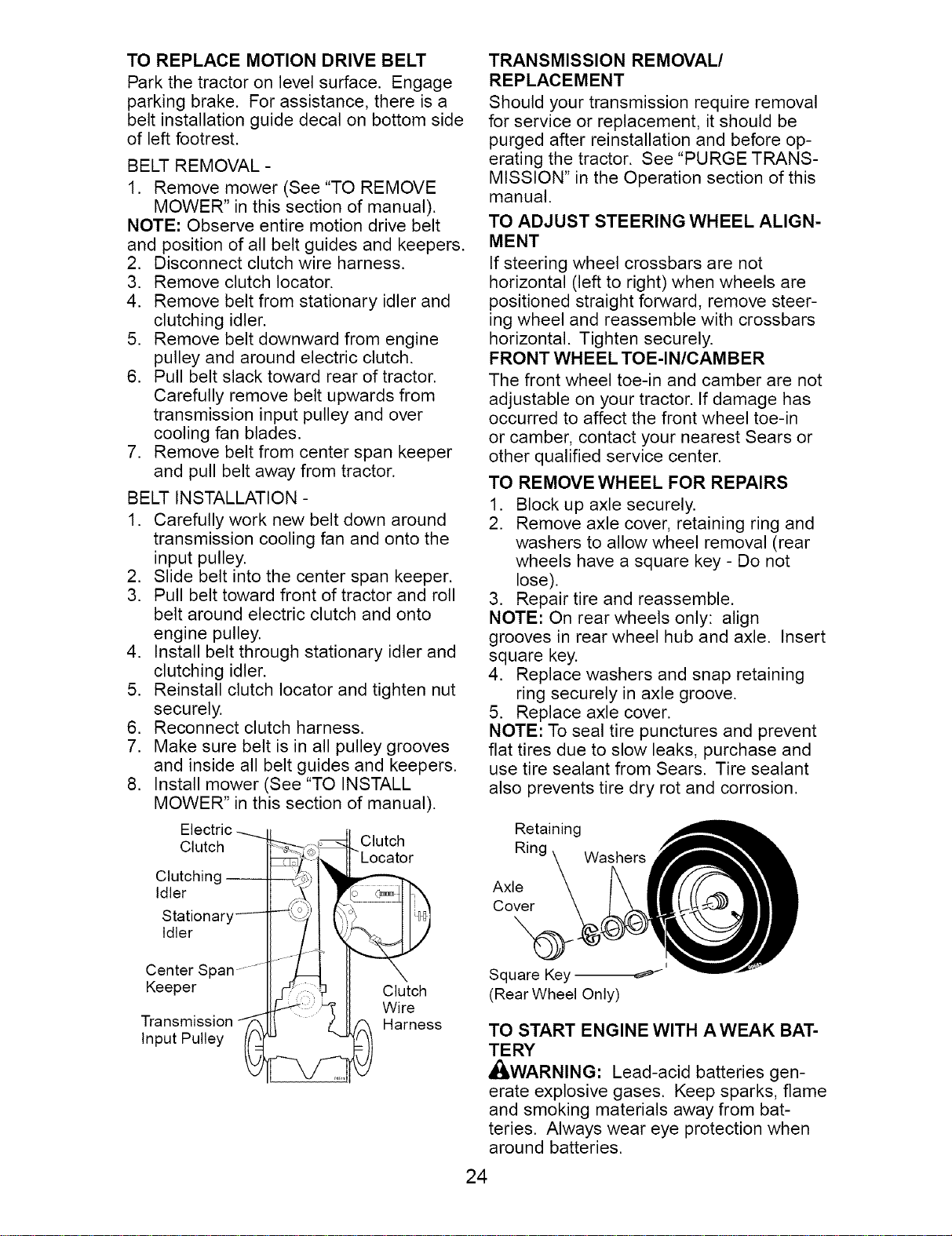
Electric -..._
Clutch
Clutching --
Idler
Stationary_
Idler
Center Span .........
Keeper
Transmission -_
Input Pulley (_
_<_ Clutch
_i_i_--_ LOcatOr
Wares i s
TRANSMISSION REMOVAL/
REPLACEMENT
Should your transmission require removal
for service or replacement, it should be
purged after reinstallation and before op-
erating the tractor. See "PURGE TRANS-
MISSION" in the Operation section of this
manual.
TO ADJUST STEERING WHEEL ALIGN-
MENT
If steering wheel crossbars are not
horizontal (left to right) when wheels are
positioned straight forward, remove steer-
ing wheel and reassemble with crossbars
horizontal. Tighten securely.
FRONT WHEEL TOE-IN/CAMBER
The front wheel toe-in and camber are not
adjustable on your tractor. If damage has
occurred to affect the front wheel toe-in
or camber, contact your nearest Sears or
other qualified service center.
TO REMOVE WHEEL FOR REPAIRS
1. Block up axle securely.
2. Remove axle cover, retaining ring and
washers to allow wheel removal (rear
wheels have a square key - Do not
lose).
3. Repair tire and reassemble.
NOTE: On rear wheels only: align
grooves in rear wheel hub and axle. Insert
square key.
4. Replace washers and snap retaining
ring securely in axle groove.
5. Replace axle cover.
NOTE: To seal tire punctures and prevent
flat tires due to slow leaks, purchase and
use tire sealant from Sears. Tire sealant
also prevents tire dry rot and corrosion.
Retaining
Ring Washers
Axle
Cover
I
Square Key
(Rear Wheel Only)
TO START ENGINE WITH A WEAK BAT-
TERY
41_WARNING: Lead-acid batteries gen-
erate explosive gases. Keep sparks, flame
and smoking materials away from bat-
teries. Always wear eye protection when
around batteries.
24
Loading ...
Loading ...
Loading ...