Loading ...
Loading ...
Loading ...
Thedryercanbeconnecteddirectlytofuseddisconnect
orcircuitbreakerboxwiththree-wire,flexiblearmoredor
non-metallicsheathedcoppercable(withgroundingwire).
Allcurrent-carryingwiresmustbeinsulated.
Aconduitconnectormustbeinstalledatjunctionbox.
Allowfourfeetofslackinthelinesodryercanbemoved
ifservicingisevernecessary.
1.Disconnectpower.
• Strip 3½ inches of outer covering from end of cable.
• _/
• Cut 1 inch of insulation from the end of each
insulated wire. Shape the end of each wire into a "U"
shaped hook.
2. Remove hold-down screw and terminal block cover.
Terminalblockcover Hold-downscrew
4. Loosen or remove terminal block screws. Connect the
neutral wire (white or center) of direct wire cable under
the center screw of the terminal block.
• Place the hook-shaped end of the wire over the
terminal block screw. The open side of the hook
should face to the right. Squeeze hook end of wire
together to form a loop.
5. Connect the other two wires to outer terminal block
screws using the same method(s) described in step 4.
Tighten all terminal block screws firmly.
6. Tighten the strain relief screws.
7. Insert tab of terminal block cover into slot of the dryer
rear panel. Secure cover with hold-down screw.
NOTE: If local codes do not permit the connection of a
frame-grounding conductor to the neutral wire, see the
instructions for "Alternate Connection."
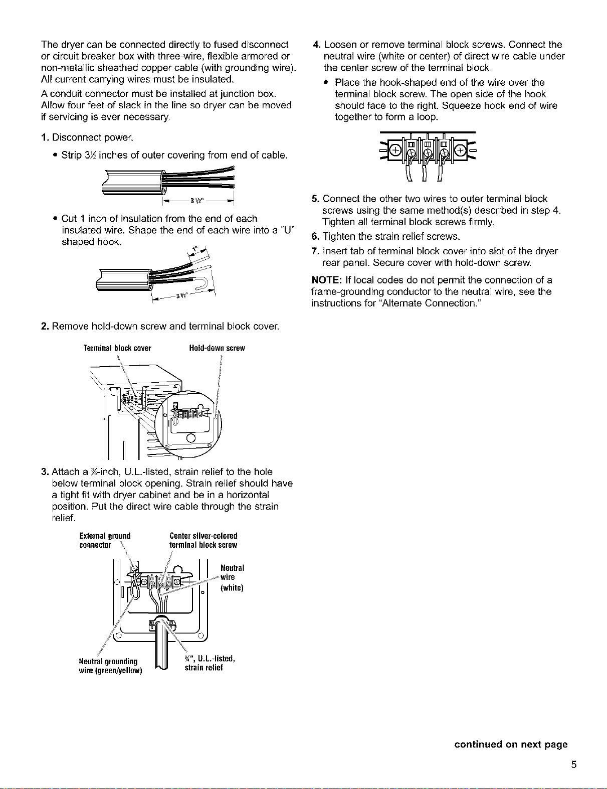
3. Attach a ¾-inch, U.L.-listed, strain relief to the hole
below terminal block opening. Strain relief should have
a tight fit with dryer cabinet and be in a horizontal
position. Put the direct wire cable through the strain
relief.
Externalground Centersilver-colored
connector terminal blockscrew
Neutral
(white)
Neutral grounding ¾", U.L-listed,
wire (green/yellow) strain relief
continued on next page
5
Loading ...
Loading ...
Loading ...