
OWNER'S MANUAL
S _A/RS
OVERLOCK 3/4D
P/N 785800851
Dear Customer:
You have just invested in a very fine overlock, Before using your new Kenmore machine, please pause for a moment and carefully read this booklet which contains
instructions on how to operate and care for your machine.
Specific instructions are given on threading, tension adjustments, cleaning, oiling, etc. This will help you obtain the best sewing results and avoid unnecessary service
expense for conditions beyond our control.
Advice on the operation and care of your machine is always available at your nearest Sears Retail Store. Please remember, if you have questions about your machine
or need parts and service, always mention the model number and serial number when you inquire.
J
J
Safety Cautions:
• Be sure that the electrical voltage of the wall outlet (wall receptacle) is the same as the rated voltage of the motor.
o Disconnect the power supply plug from the wall outlet when changing needles, presser foot or needle plate, or when leaving the machine unattended.
This eliminates the possibility of starting the machine by accidentally pressing the foot control.
• All covers must be closed when operating the machine.
• Do not pull the fabric while you are stitching as this may deflect the needle, causing it to break.
• Before cleaning your machine, disconnect the power supply plug from the wall outlet.
• Do not attempt to adjust the motor belt. Contact your nearest Service Center should any adjustment be required.
e Handle the foot control with care and avoid dropping it on the floor. Be sure not to place anything on top of it.
e Closely watch the area being sewn to avoid injuries from needles and knives.
® Use only the handle to lift and move the machine.
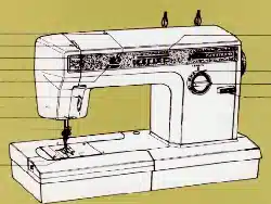
Kenmore Overlock
Record in space provided below the model number and serial
number of this appliance. The model number and serial number
are located on the nomenclature plate, as identified on Page 2 of
this booklet.
Model No. 385. Serial No
Retain these numbers for future reference.
10111,
11607,
12321,
12491,
12581,
12714,
12841,
17881
15841,
17822,
17928
18830,
19501,
15641,
16642
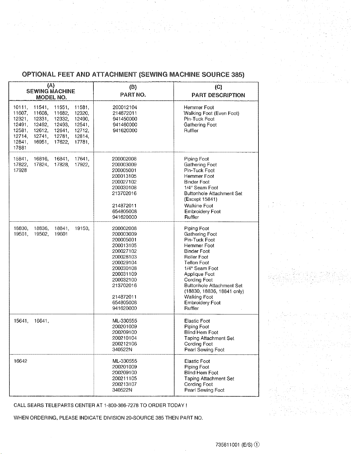
OPTIONAL FEET AND ATTACHMENT (SEWING MACHINE SOURCE 385)
(A)
SEWING MACHINE
MODEL NO.
11541, 11551, 11581,
11608, 11682, 12320,
12331, 12332, 12490,
12492, 12493, 12541,
12612, 12641, 12712,
12741, 12781, 12814,
16951, 17622, 17781,
16816, 16841, 17641,
17824, 17828, 17922,
18836, 18841, 19150,
19502, 19601
16641,
(B)
PART NO.
200012104
214872011
941450000
941460000
941620000
200002008
200003009
200005001
200013105
200027102
200030108
213702016
214872011
654805008
941620000
200002008
200003009
200005001
200013105
200027102
200028103
200029104
200030108
200031109
200032100
213702016
214872011
654805008
941620000
ML-330555
200201009
200209100
200210104
200212106
340522N
ML-330555
200201009
200209100
200211105
200213107
340522N
(c)
PART DESCRIPTION
Hemmer Foot
Walking Foot (Even Foot)
Pin-Tuck Foot
Gathering Foot
Ruffler
Piping Foot
Gathering Foot
Pin-Tuck Foot
Hemmer Foot
Binder Foot
1/4" Seam Foot
Buttonhole Attachment Set
(Except 15841)
Walkine Foot
Embroidery Foot
Ruffler
Piping Foot
Gathering Foot
Pin-Tuck Foot
Hemmer Foot
Binder Foot
Roller Foot
Teflon Foot
1/4" Seam Foot
Applique Foot
Cording Foot
Buttonhole Attachment Set
(18830, 18836, 18841 only)
Walking Foot
Embroidery Foot
Ruffler
Elastic Foot
Piping Foot
Blind Hem Foot
Taping Attachment Set
Cording Foot
Pearl Sewing Foot
Elastic Foot
Piping Foot
Blind Hem Foot
Taping Attachment Set
Cording Foot
Pearl Sewing Foot
CALL SEARS TELEPARTS CENTER AT 1-800-366-7278 TO ORDER TODAY !
WHEN ORDERING, PLEASE INDICATE DIVISION 20-SOURCE 385 THEN PART NO.
iI
735811001 (E/S)(_.[_
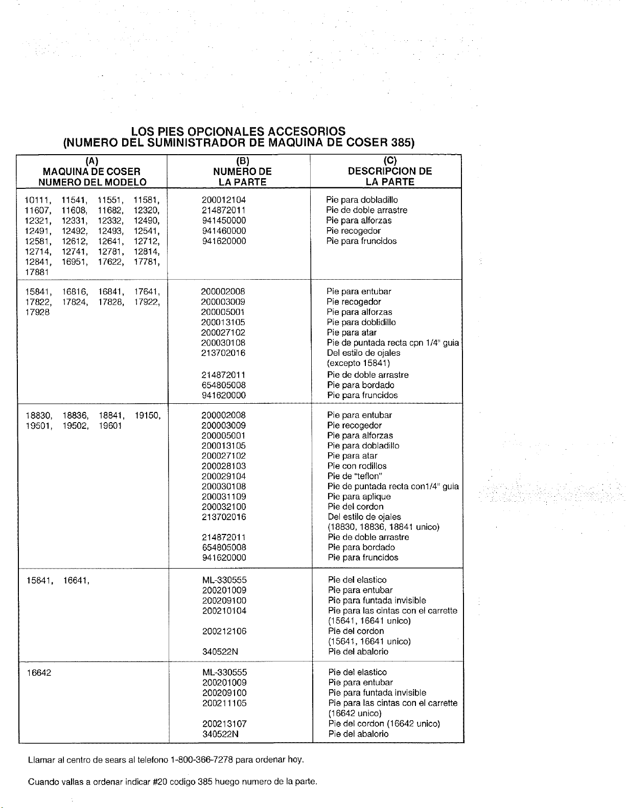
LOS PIES OPCIONALES ACCESORIOS
(NUMERO DEL SUMINISTRADOR DE MAQUINA DE COSER 385)
(A) (R) (C)
MAQUINA DE COSER NUMERO DE DESCRIPCION DE
NUMERO DEL MODELO LA PARTE LA PARTE
t0111, 11541, 11551, 11581,
11607, 11608, 11682, 12320,
12321, 12331, 12332, 12490,
12491, 12492, 12493, 12541,
12581, 12612, 12641, 12712,
12714, 12741, 12781, 12814,
12841, 16951, 17622, 17781,
17881
15841, 16816, 16841, 17641,
17822, 17824, 17828, 17922,
17928
18830, 16836, 18841, 19150,
19501, 19502, 19601
15641, 16641,
16642
200012104
214872011
941450000
941460O00
94162000O
200002008
200003009
200005001
200013105
200027102
200030108
213702016
214872011
654805008
941620000
200002008
200003009
200005001
200013105
200027102
200028103
200029104
200030108
200031109
200032100
213702016
214872011
654805008
941620000
ML-330555
200201009
20020910O
200210104
200212106
340522N
M_330555
200201009
200209100
200211105
Pie para dobladillo
Pie de doble arrastre
Pie para alforzas
Pie recogedor
Pie para fruncidos
Pie para entubar
Pie recogedor
Pie para alforzas
Pie para doblidillo
Pie para atar
Pie de puntada recta cpn 1/4' guia
Del estilo de ojales
(excepto 15841 )
Pie de doble arrastre
Pie para bordado
Pie para fruncidos
Pie para entubar
Pie recogedor
Pie para alforzas
Pie para dobladillo
Pie para afar
Pie con rodillos
Pie de "teflon"
Pie de puntada recta conl/4" guia
Pie para aplique
Pie del cordon
Del estilo de ojales
(18830, 18836, 18841 unico)
Pie de doble arrastre
Pie para bordado
Pie para fruncidos
Pie del elastico
Pie para entubar
Pie para funtada invisible
Pie para las cintas con el carrette
(15641, 16641 unico)
Pie del cordon
(15641, 16641 unico)
Pie del abalorio
200213107
340522N
Pie del elastico
Pie para entubar
Pie para funtada invisible
Pie para las cintas con el carrette
(16642 unice)
Pie del cordon (16642 unico)
Pie del abalorio
Llamar al centro de sears al telefono 1-800-366-7278 para ordenar hoy.
Cuando vallas a ordenar indicar #20 codigo 385 huego numero de la parte.
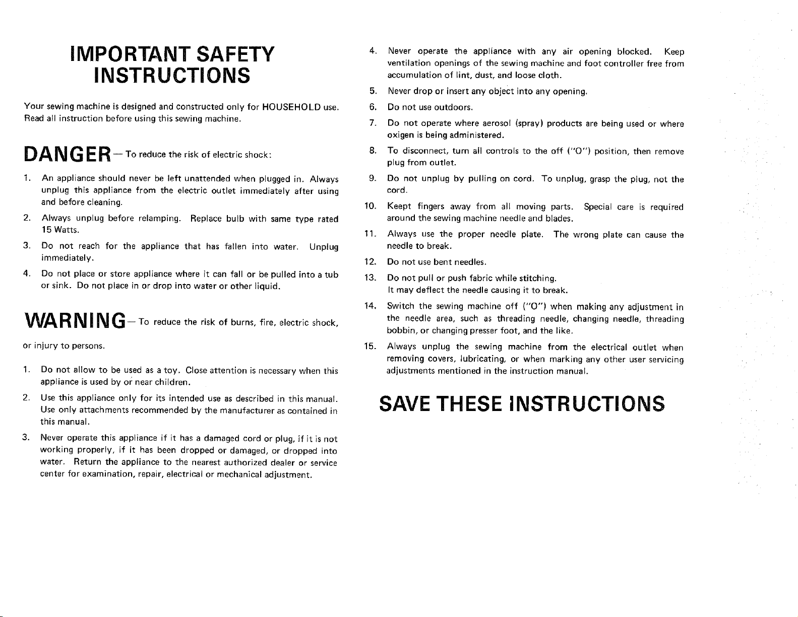
IMPORTANT SAFETY
INSTRUCTIONS
Your sewing machine is designed and constructed only for HOUSEHOLD use.
Read all instruction before using this sewing machine.
DA N GER- Toreduce the risk of electric shock:
2.
3.
4.
An appliance should never be left unattended when plugged in. Always
unplug this appliance from the electric outlet immediately after using
and before cleaning.
Always unplug before relamping. Replace bulb with same type rated
15 Watts.
Do not reach for the appliance that has fallen into water. Unplug
immediately.
Do not place or store appliance where it can fall or be pulled into a tub
or sink. Do not place in or drop into water or other liquid.
WAR NI NG- Toreduce the risk of burns, fire, electric shock,
or injury to persons.
1. Do not allow to be used as a toy, Close attention is necessary when this
appliance is used by or near children.
2. Use this appliance only for its intended use as described in this manual.
Use only attachments recommended by the manufacturer as contained in
this manual.
3.
Never operate this appliance if it has a damaged cord or plug, if it is not
working properly, if it has been dropped or damaged, or dropped into
water. Return the appliance to the nearest authorized dealer or service
center for examination, repair, electrical or mechanical adjustment.
4,
5.
6.
7.
8.
9.
10.
11,
12.
13.
14,
15.
Never operate the appliance with any air opening blocked. Keep
ventilation openings of the sewing machine and foot controller free from
accumulation of lint, dust, and loose cloth.
Never drop or insert any object into any opening.
Do not use outdoors.
Do not operate where aerosol (spray) products are being used or where
oxigen is being administered.
To disconnect, turn all controls to the off ("0") position, then remove
plug from outlet.
Do not unplug by pulling on cord. To unplug, grasp the plug, not the
cord.
Keept fingers away from all moving parts. Special care is required
around the sewing machine needle and blades.
Always use the proper needle plate. The wrong plate can cause the
needle to break.
Do not use bent needles.
Do not pull or push fabric while stitching.
It may deflect the needle causing it to break.
Switch the sewing machine off ("0") when making any adjustment in
the needle area, such as threading needle, changing needle, threading
bobbin, or changing presser foot, and the like.
ALways unplug the sewing machine from the electrical outlet when
removing covers, lubricating, or when marking any other user servicing
adjustments mentioned in the instruction manual.
SAVE THESE INSTRUCTIONS
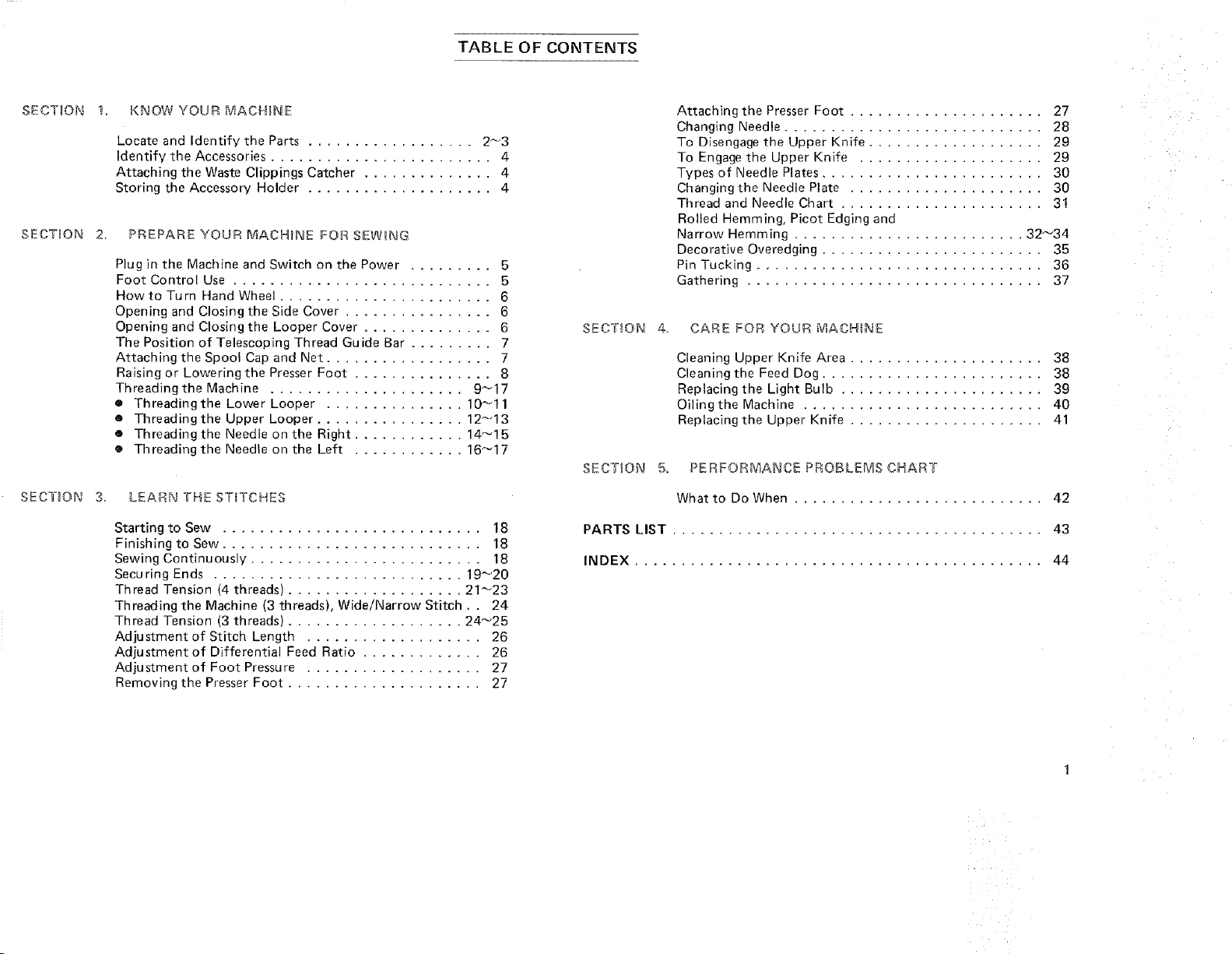
TABLE OF CONTENTS
SECTION
SECTION 2.
SECTION 3,
1_ KNOW YOUR MACHINE
Locate and Identify the Parts .................. 2_3
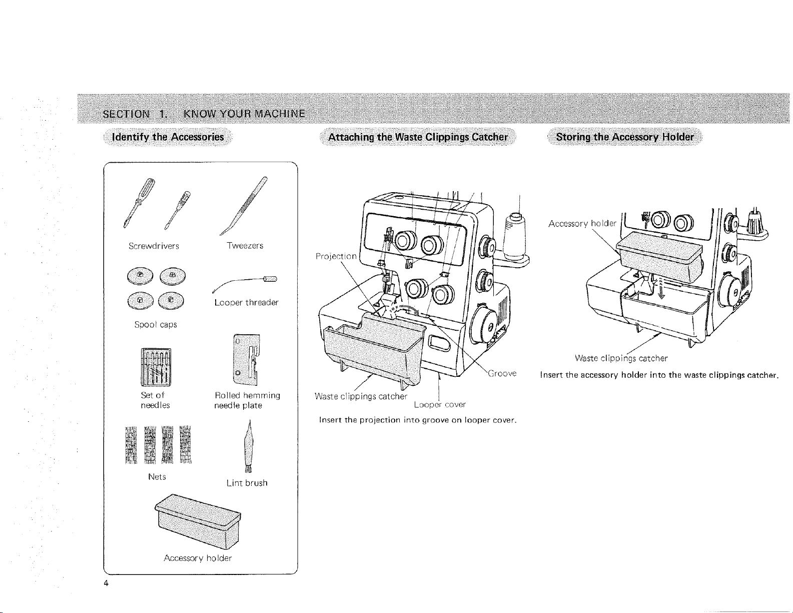
Identify the Accessories ........................ 4
Attaching the Waste Clippings Catcher .............. 4
Storing the Accessory Holder .................... 4
PREPARE YOUR MACH#NE FOR SEWHNG
Plug in the Machine and Switch on the Power ......... 5
Foot Control Use ............................ 5
Howto Turn Hand Wheel ....................... 6
Opening and Closing the Side Cover ................ 6
Opening and Closing the Looper Cover .............. 6
The Position of Telescoping Thread Guide Bar ......... 7
Attaching the Spool Cap and Net .................. 7
Raising or Lowering the Presser Foot ............... 8
Threading the Machine ..................... 9_17
• Threadingthe Lower Looper ............... 10_11
• Threading the Upper Looper ................ 12_13
• Threading the Needle on the Right ............ 14_15
® Threading the Needle on the Left ............ 16_17
LEARN THE STITCHES
Starting to Sew ............................ 18
Finishing to Sew ............................ 18
Sewing Continuously ......................... 18
Securing Ends ........................... 19_20
Thread Tension (4 threads) ................... 21_23
Threading the Machine (3 threads), Wide/Narrow Stitch.. 24
Thread Tension (3 threads) ................... 24_25
Adjustment of Stitch Length ................... 26
Adjustment of Differential Feed Ratio ............. 26
Adjustment of Foot Pressure ................... 27
Removing the Presser Foot ..................... 27
Attaching the Presser Foot ..................... 27
Changing Needle ............................ 28
To Disengage the Upper Knife ................... 29
To Engage the Upper Knife .................... 29
Types of Needle Plates ........................ 30
Changing the Needle Plate ..................... 30
Thread and Needle Chart ...................... 31
Rolled Hemming, Picot Edging and
Narrow Hemming ......................... 32_34
Decorative Overedging ........................ 35
Pin Tucking ............................... 36
Gathering ................................ 37
SECTION 4. CARE FOR YOUR MACHINE
Cleaning Upper Knife Area ..................... 38
Cleaning the Feed Dog ........................ 38
Replacing the Light Bulb ...................... 39
Oiling the Machine .......................... 40
Replacing the Upper Knife ..................... 41
SECTION 5, PERFORMANCE PROBLEMS CHART
What to Do When ........................... 42
PARTS LIST ........................................ 43
INDEX ............................................ 44
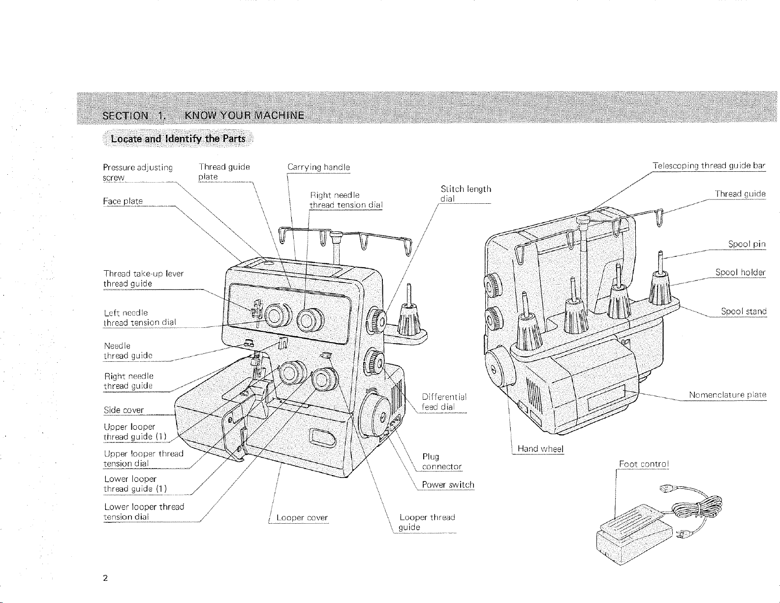
Pressureadjusting Threadguide
screw plate
t
Face plate \
\
\
\ \
Thread take+up lever
thread guide
Left needle
thread tension dial
Nead le
thread guide
Right needle
thread guide
Side cover
Upper looper
thread guide (1)
Upper looper thread
tension dial
Lower looper /
!breadgu!de!!!....... //
/
/
Lower looper thread /
tension diai
/
Carrying handle
Right needle
thread tension dial
J
]
/
/
/ Looper cover
L
\
\
Stitch length
dial
/
/
/
/
Differential
feed dial
\
\
,,_ Plug
',, ,Lcon.nector
\ Power switch
\
\
, Looper thread
_+g+ui+d+e...........................
Hand wheel
Telescoping thread guide bar
Thread guide
Spoolpin
Spool holder
Spool stand
Nomenclature plate
Foot control
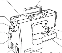
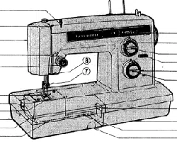
SECTION
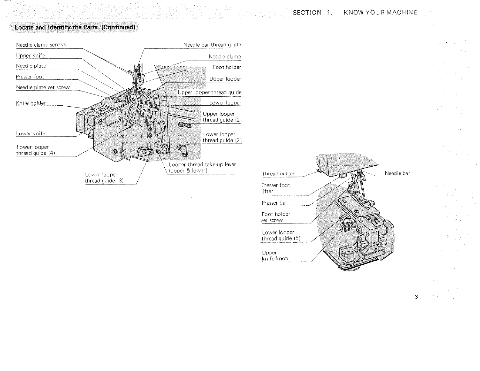
1: KNOW YOUR MACHINE
Needle clamp screws
Upper knife
Needle plate
Presser foot "_-_.
Needle plate set screw
Knife holder
Lower knife
Lower looper
thread guide (4)
_f
Lower looper
thread guide (3)
/
Needle bar thread guide
Needle clamp
Foot holder
Upper looper
Upper looper thread guide
Lower Ioo_
Upper looper
thread guide (2)
Lower looper
thread guide /2)
Looper thread take-up lever
'\..!.u...P_2e_& l?wer) ....................
Thread cutter
Presser foot
lifter
Presser bar
Foot holder
set screw
Lower looper
thread guide (5)
Upper
knife knob
/
Screwdrivers
QQ
GQ
Spool caps
@
Set of
needles
/
Tweezers
Looper threader
Rolled hemming
needle plate
Nets
Lint brush
Accessory holder
I
I
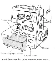
Projection
\
)ov@
J
Waste clippings catcher
Looper cover
Insert the projection into groove on looper cover.
Accessory ho Ider @
Waste clippings catcher
Insert the accessory holder into the waste clippings catcher.
SECTION . PREPARE YOUR MACHINE FOR SEWING
Foot Control Use
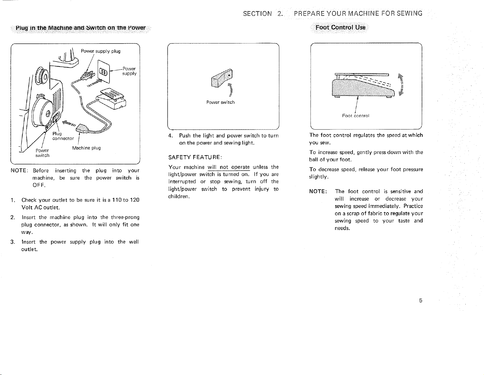
Power supply plug
supply
Plug
connector
Machine plug
Power
switch
NOTE: Before inserting the plug into your
machine, be sure the power switch is
OFF.
1.
2.
3.
Check your outlet to be sure it is a 110 to 120
Volt AC outlet.
Insert the machine plug into the three-prong
plug connector, as shown. It will only fit one
way.
Insert the power supply plug into the wall
outlet.
Power switch
4. Push the light and power switch to turn
on the power and sewing light.
SAFETY FEATU RE:
Your machine will not operate unless the
light/power switch is turned on. If you are
interrupted or stop sewing, turn off the
light/power switch to prevent injury to
children.
¢
/
Foot coR'_rol
The foot control regulates the speed at which
you sew.
To increase speed, gently press down with the
bail of your foot.
To decrease speed, release your foot pressure
slightly.
NOTE: The foot control is sensitive and
will increase or decrease your
sewing speed immediately. Practice
on a scrap of fabric to regulate your
sewing speed to your taste and
needs.
7 i ¸¸
i i _ ;_i •ii;i ii
•• • iiii !iii
i i,j _ i
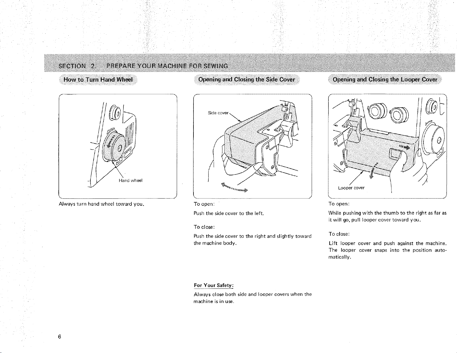
How to Turn Hand Wheel =
Always turn hand wheel toward you.
Side cover _.
To open:
Push the side cover to the left.
To close:
Push the side cover to the right and slightly toward
the machine body.
S
Looper cover
To open:
While pushing with the thumb to the right as far as
it will go, pull looper cover toward you.
To close:
Lift looper cover and push against the machine.
The looper cover snaps into the position auto-
matically.
For Your Safety:
Always close both side and looper covers when the
machine is in use.
6
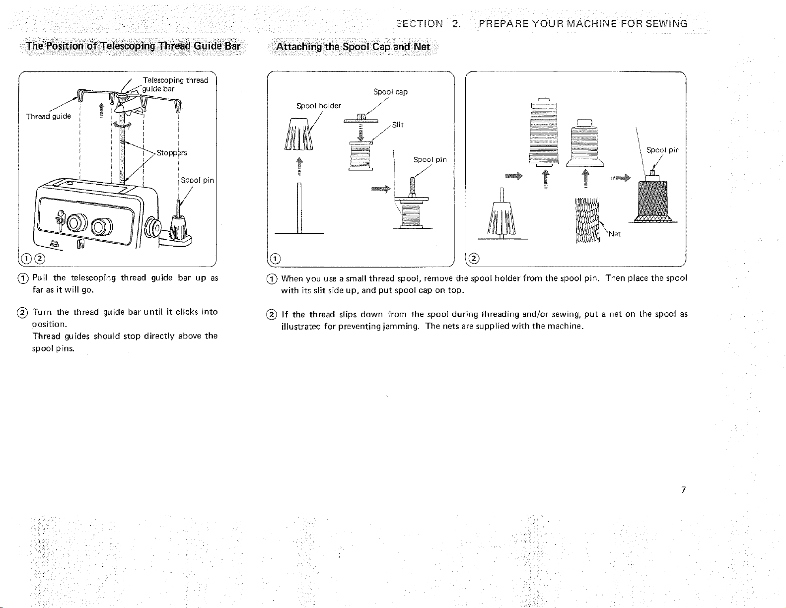
The Position of Telescoping Thread Guide Bar
SECTION 2. PREPARE YOUR MACHINE FOR SEWING
Attaching the Spool Cap and Net
f
f
/
Thread guide
Telescoping thread
"guide bar
_Stoppers
G® .
(_ Pull the telescoping thread guide bar up as
far as it will go.
Turn the thread guide bar until it clicks into
position,
Thread guides should stop directly above the
spool pins,
Spool cap
Spool holder /
/
_ _ /.Slit
==_.
t _ Spool pin
t t
Spool pin
D
.... J
(_ When you use a small thread spool, remove the spool holder from the spool pin. Then place the spool
with its slit side up, and put spool cap on top.
(_) If the thread slips aown from the spool during threading and/or sewing, put a net on the spoo as
illustrated for preventing jamming. The nets are supplied with the machine.
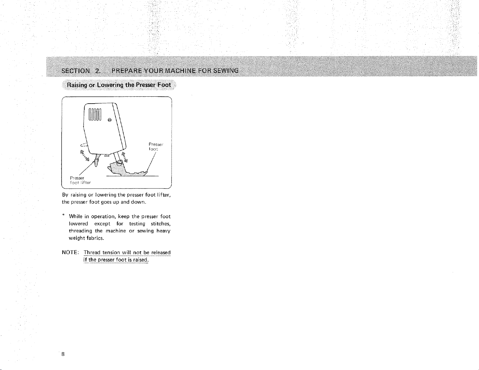
Raising or LOwering the Presser Foot
\
/
f
Presser
foot ifter
J
By raisin 9 or lowering _ne presser foot lifter,
the _resser foot goes up and down.
While in operation, keep tiqe Dresser foot
owered except for testing stitches,
threading the machine or sewing heavy
weight fabrics.
NOTE: Thread tension will not be released
if the presser foot is raised.
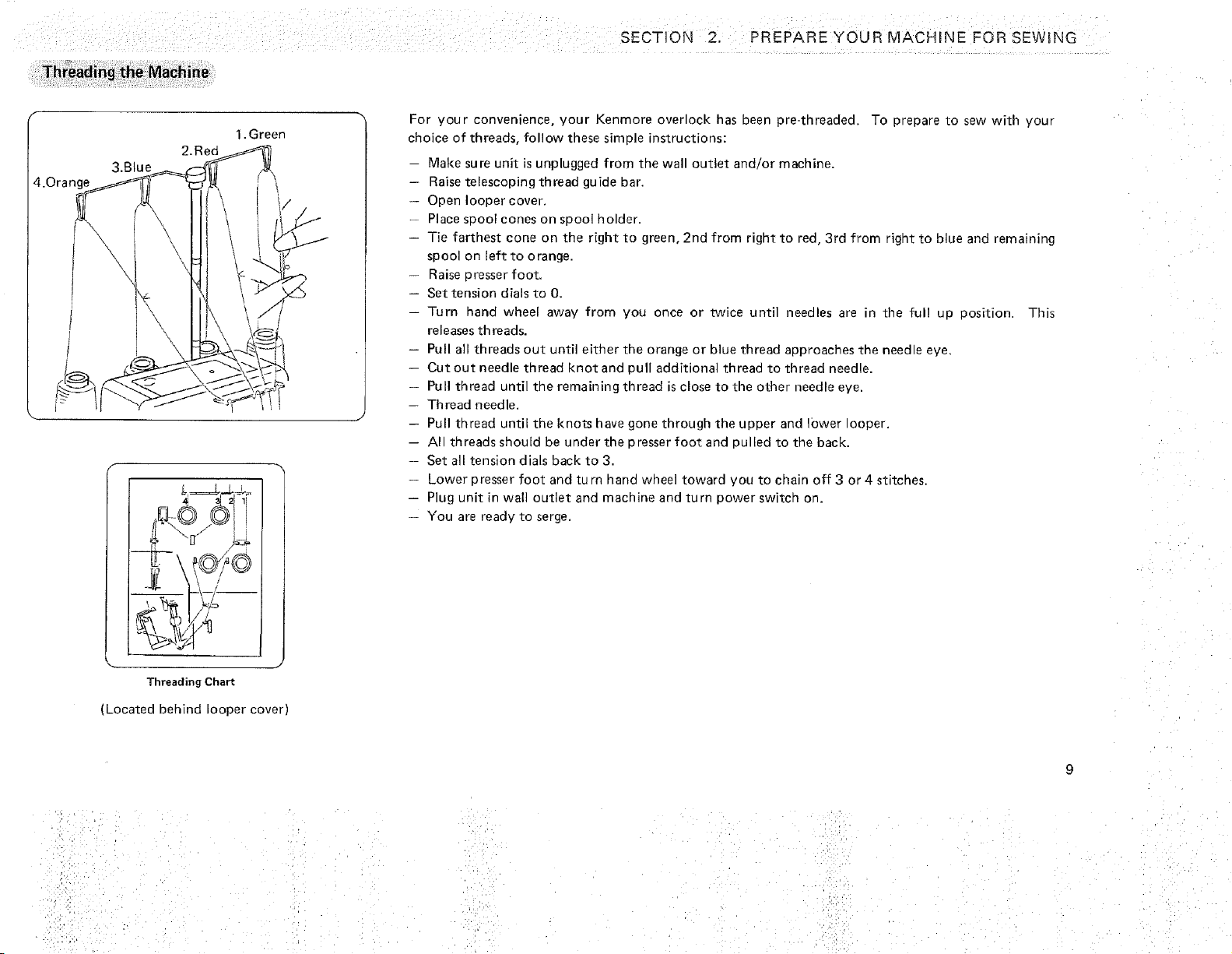
Threading the Machine
SECTUON 2. PREPARE YOUR _4ACHINE FOR SEWING
_.Orange
&Blue
2.Red
1. Green
\
# =====_.._
DL/'/_
Threading Chart
ILocated behind ooper cover)
For your convenience, your Kenmore overlock has been pre-threaded. To prepare to sew with your
choice of threads, follow these simple instructions:
Make sure unit is unplugged from the wall outlet and/or machine.
- Raise telescoping thread guide bar.
Open looper cover.
Place soool cones on soool holder.
Tie farthest cone on the right to green, 2nd from right to red, 3rd from right to blue and remaining
spool on left to orange.
Raise 3resser foot,
Set tension dials to 0.
Turn hand wheel away from you once or twice until needles are in the ful! up position. This
releases th reads.
Pull all threads out until either the orange or blue thread approaches the needle eve.
Cut out needle thread knot and oull addition al thread to thread needle.
Pull thread until the remaining thread is close to the other needle eye.
Th read needle.
-- Pull thread until the knots have gone through the upper and lower ooper.
AI threads should be under the presser foot and pulled to the back.
Set all tension dials back to 3.
Lower presser foot and turn hand wheel toward you to chain off 3 or 4 stitches.
Plug unit in wall outlet and machine and turn power switch on.
You are ready to serge.
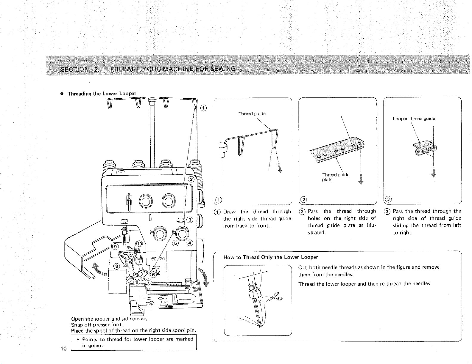
Threading the Lower Looper
©©
Open the looper and side covers.
Snap off presser foot.
Place the spool of thread on the right side soool pin.
I - Points to thread for lower Ioooer are marked
10 in green.
_J
Thread guide
\\
'x
1_ Draw the thread through
the right side thread guide
from back to front,
Thread guide
31ate
(_) Pass the thread througn
holes on the right side of
thread guide plate as illu-
strated,
Looper thread guide
\
(_ Pass the thread through the
right side of thread guide
sliding the thread from left
to right.
How to Thread Only the Lower Looper
Cut both needle threads as shown in the figure ana remove
them from the needles.
Thread the lower looper and then re-thread the needles.
SECTION 2. PREPARE YOUR MACHINE FOR SEWING
Lower
ooper
tnreaa
guide (1
¢
Lower
looper threat
tension dial
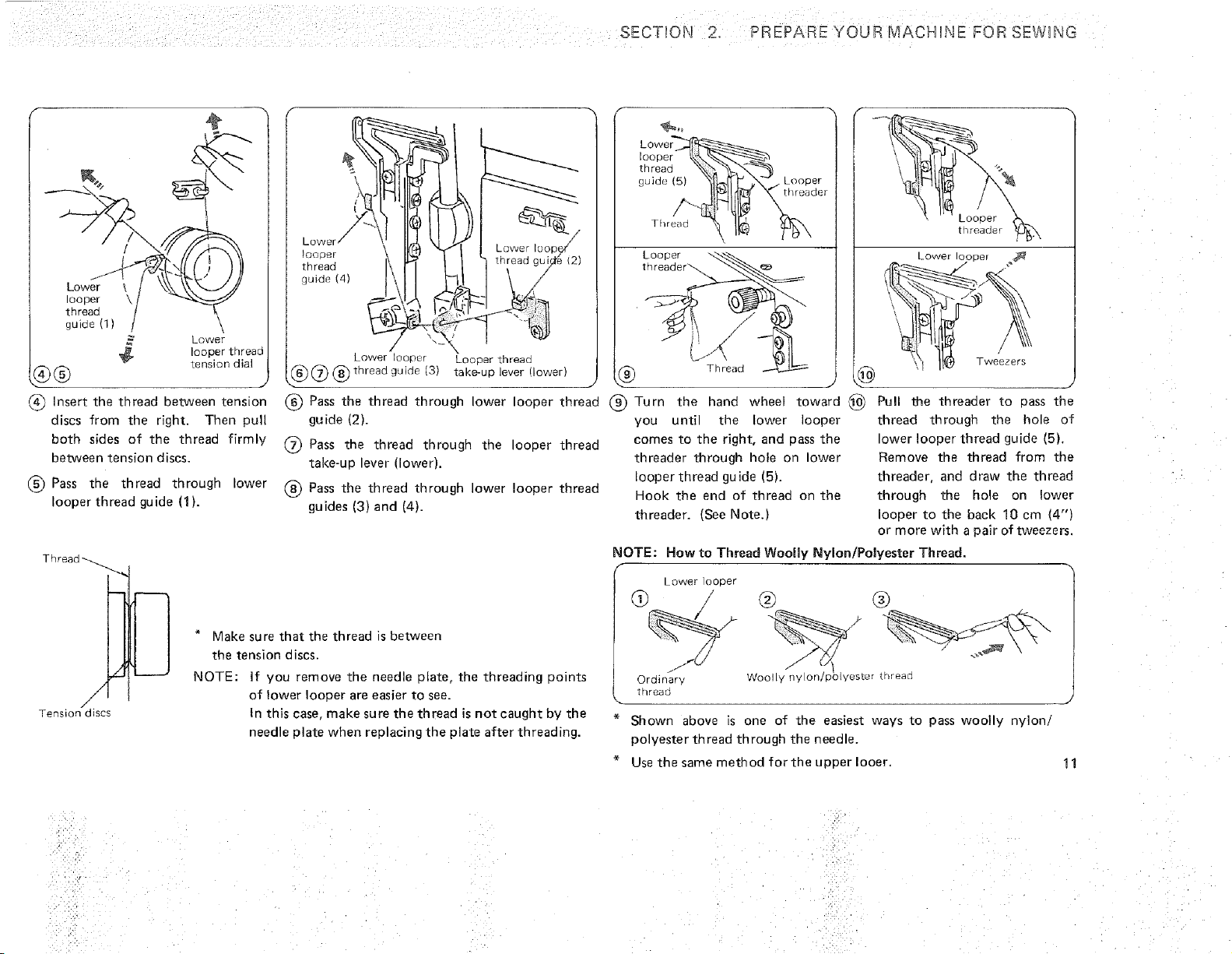
f_ Insert the thread between tension
discs from the right. Then pull
both sides of the thread firmly
between tension discs.
(_ Pass the thread through lower
looper thread guide (1).
\
LOWel
!oooer
thread
guide (4)
thread gui
Lower oopef Loooar threac
6_ (_ (_ tnread guide (3)take-up lever uower_
Lowe_
looper _,'k.%.-'_
thread _X,_ "_'_._
{side(5) Slb_ _.-#_ Looper
Th,ead "\ I_ _J_X
Looper _.
threader_
Thread ._-_
Loooer
[r]r_aoer
Lower OODer _
Tweezers
(_ Pass the thread through ower looper thread 1_ Turn the _and wheel toward ,_ Pull !_e threader to aass the
guide (2).
(_) Pass the thread through the looper thread
take-up lever (lower).
(_) Pass the thread through lower looper thread
guides (3) and {4).
you until the lower looper
comes to the right, and pass the
threader through hole on lower
looper thread guide (5).
Hook the end of threao on the
threader. (See Note.}
thread through the hole of
lower looper thread guide (5).
Remove the thread frorr the
threader, and draw the thread
through the hole on lower
looper to the back 10 cm (4")
or more with a pair of tweezers.
Thread
Z
/
/
Tension d_ses
* Make sure that the thread is between
the tension discs.
NOTE: If you remove the needle olate, the threading points
of lower looper are easier to see.
In this case, make sure the thread is not caught by the
needle plate when replacing the plate after threading.
NOTE: How to Thread Woolly Nylon/Polyester Thread.
Lower ooDer
@ / @ @
©rdinar. WoolIv n', on!pb _ ester -qreao
[rlreao
* Shown above is one of the easiest ways to pass woolly nylon!
polyester thread through the needle.
* Use the same method for the upper Iooer,
11
SECTION 2_ PREPARE UR MACHINE JFOR,SEW NG> _ _ :,
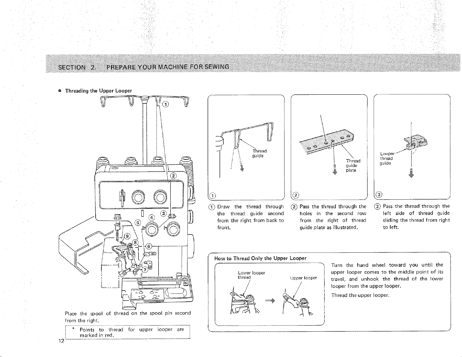
e Threading the Upper Looper
, ,
1_ Draw the thread through
the thread guide second
from the right from back to
front.
= guide
plate
_) Pass the thread through the
holes ir the second row
from the right of threa_
guide plate as illustrated.
Looper
_hread
guide
g
(_) Pass the thread througn the
left side of thread guide
sliding the thread from right
_o left.
Place the spool of thread on the spool pin second
from the right.
[ * Points to thread for upper looper are
I marked in red.
E
12
f
How to Thread Only the Upper Looper
F
Lower looper
thread Upper looper
Turn the hand wheel toward you until the
upper looper comes to the middle point of its
travel, and unhook the thread of the lower
looper from the upper looper.
Thread the upper looper.
SECTION 2. PREPARE YOUR MACH_NE FOR SEW NG
,t
I "
guide (t) X uDDer
1Doper thread
4_(_) ¢ tension dial
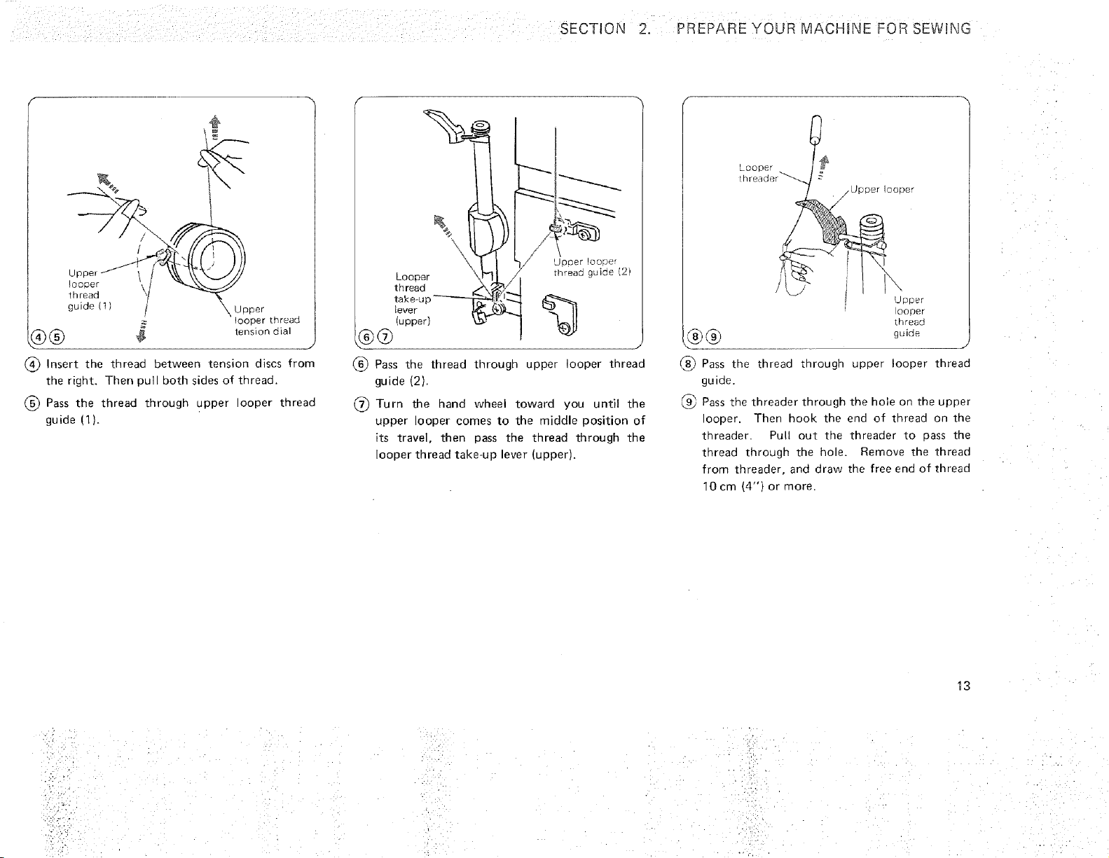
(_ Insert the thread between tension discs from
the right. Then pull both sides of thread.
Pass the thread through upper Doper thread
guide (1).
Looper
tiqread
take-u
lever
fupper)
®@
'J'DID e r IooDer
rlqreao guide _2
9
(_) Pass the thread througn upper looper thread
guide (2).
Turn the hand wheel toward you until tne
upper looper comes to the middle position of
its travel, then pass the thread through _ne
looper thread take-up lever (upper),
LOC Der t_
threade_
z U[JD_r lOOPer
\
UDDer
DoPer
Lrlre_o
gLJ igJe
(_ Pass the thread _nrough upper looper thread
guide.
k_ Pass the threader through the hole on the upper
ooper. Then hook the end of tnreaa on the
tnreaaer. Pull ou_ tne threader to oass the
thread through the hole. Remove the thread
from threader, and draw the free ena of thread
10cm (4") or more.
13
HINE ::FOR SEWI NG ,: :,:_
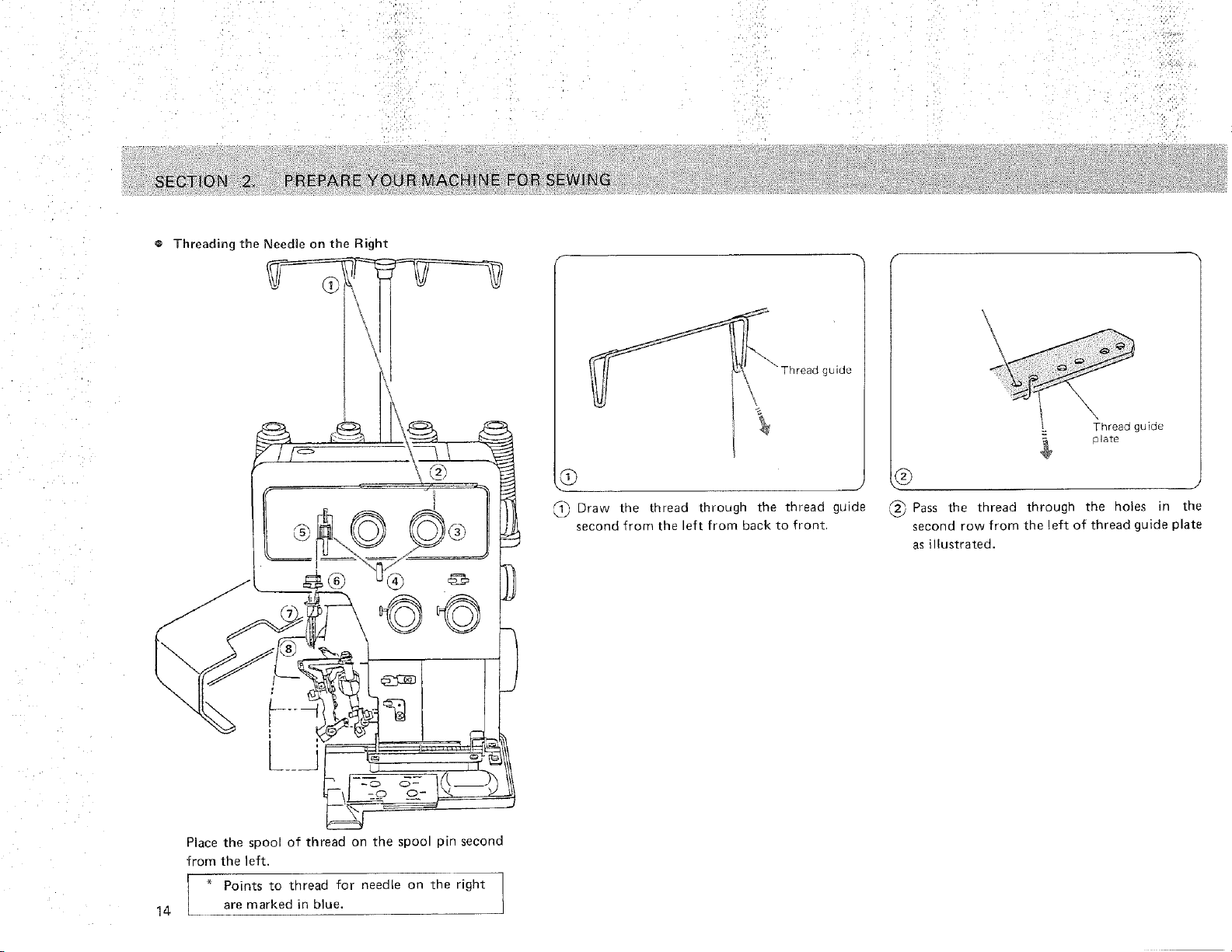
o Threading the Needle on the Right
_ Thread _uide
,D
J
_ Draw the thread through the thread guide
second from the eft from back to front.
$
Thread gurde
_ Pass the tnreaa tnrough the holes in the
second row from the left of thread guide plate
as illustrated.
14
Place the spool of thread on the spool pin second
from the left.
* Points to thread for needle on the right
are marked in blue.
SECTION 2. PREPARE YOUR MACHINE FORSEWING
\
Right needle threactension dia
J
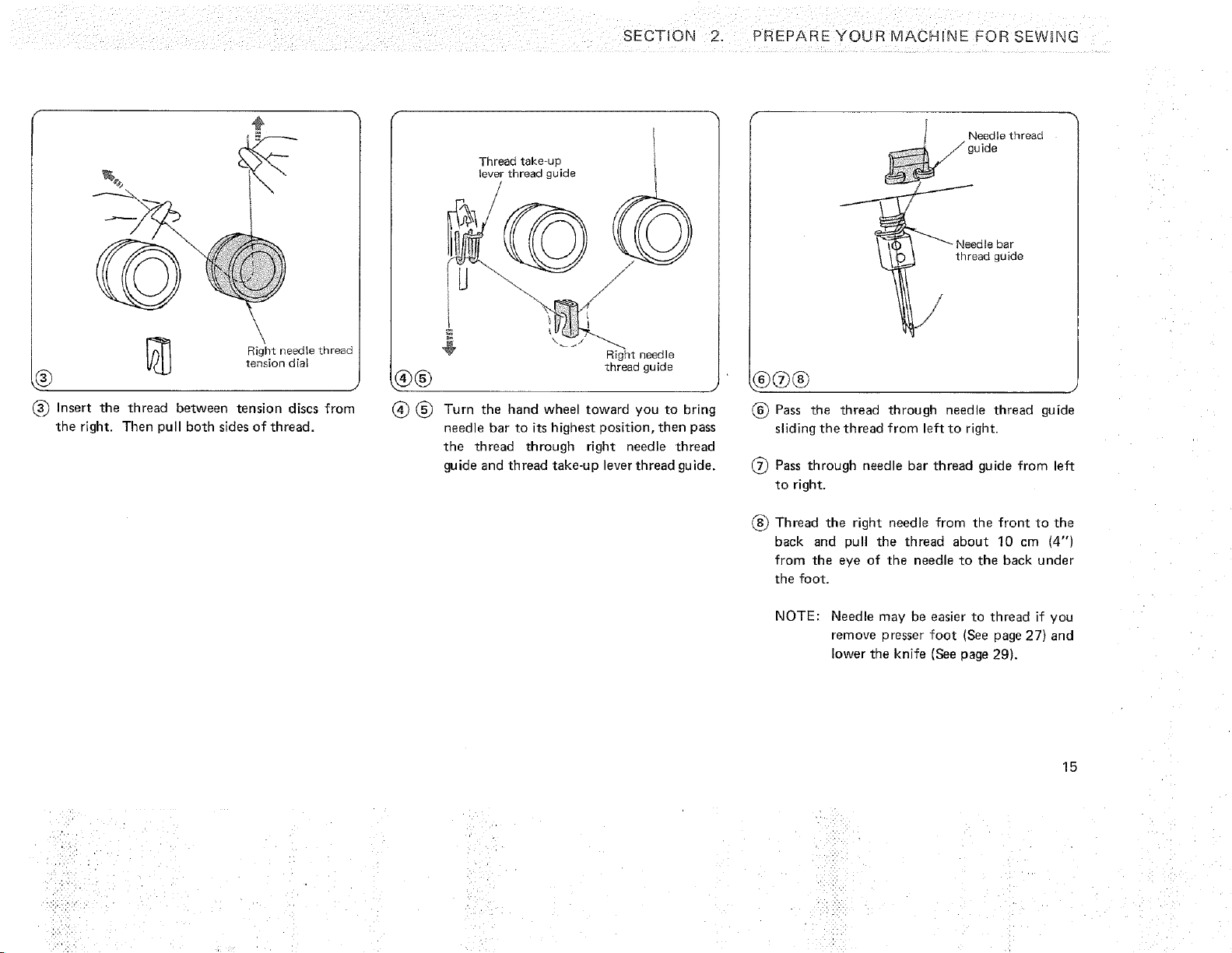
_-_ Insert the thread between tension discs from
the right. Then pul both sides of thread.
Thread take up
lever thread guide
±
÷
Rig_lt needle
thread guide
(_ (_ Turn the hand wheel toward you to bring
needle bar to its higllest oosition, then pass
the thread through right needle thread
guide and thread take-up lever thread guide.
Needte threaa
u ide
Needle par
thread guide
t/
® Pass the thread through needle thread guide
sliding the thread from left to right.
(_ Pass through needle bar thread guide from left
to right.
® Thread the right needle from tne front to the
back and Dull the thread about 10 cm {4"1
from the eye of the needle to the back under
the foot.
NOTE: Needle may be easier to thread if you
remove oresser foot (See page 27) and
lower the knife [See page 29).
15
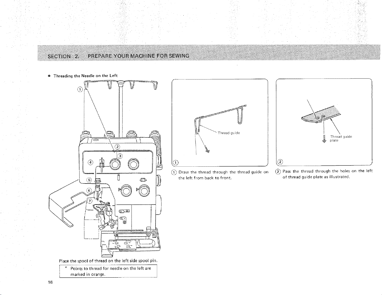
o Threading the Needle on the Left
J
J
J
Draw the thread through the thread guide on
the left from back to front.
Thread guide
plate
b
(_) Pass the thread through the holes on the left
of thread guide plate as illustrated.
16
Place the spool of thread on the left side spool pin.
" Points to thread for needle on the left are
marked in orange.
SECTION 2. PREPARE YOUR MACHINE FORSEWgNG
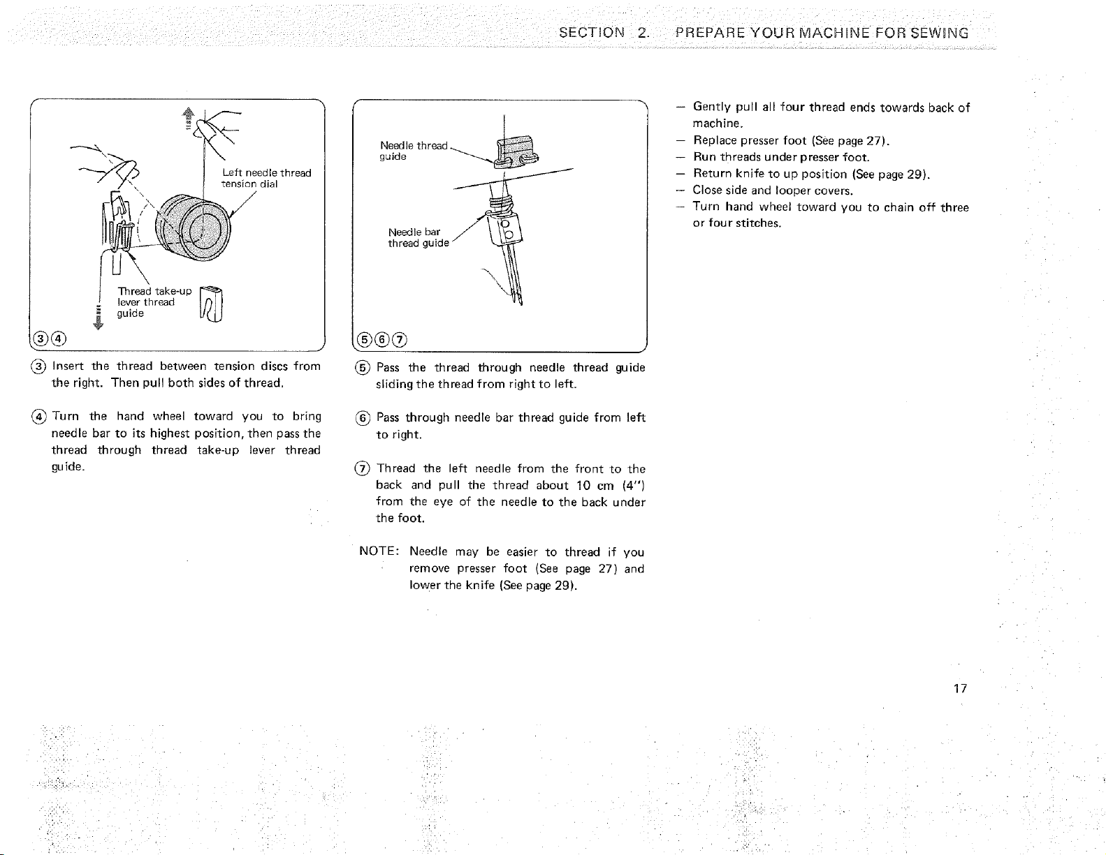
Left needle tnreaa
tension dial
\N ;
Thread take-uu _
ever thread
guide
9®
(_ Insert the thread between tension discs from
the right. Then pull both sides of thread.
(_) Turn the hand wheel toward you to bring
needle bar to its highest position, then pass the
thread through thread take-up lever thread
gu ide.
Needle thread ...
guide
Needle bar
thread guic
\
b®db
® Pass the thread through needle thread guide
sliding the thread from right to left.
Pass through needle bar thread guide from left
to right.
(_ Thread the left needle from the front to tne
back and pull the thread about 10 cm (4")
from the eye of the needle to the back under
the foot.
NOTE: Needle may be easier to thread if you
remove presser foot (See page 27) and
lower the knife (See page 29).
Gently pull all four thread enes towards back of
machine.
Replace presser foot (See page 27).
Run threads under presser foot.
-- Return knife to uu position (See page 29).
Close side and looper covers.
Turf hand wheel toward you to chain off three
or four stitches.
17
SECTION
Finishing to Sew
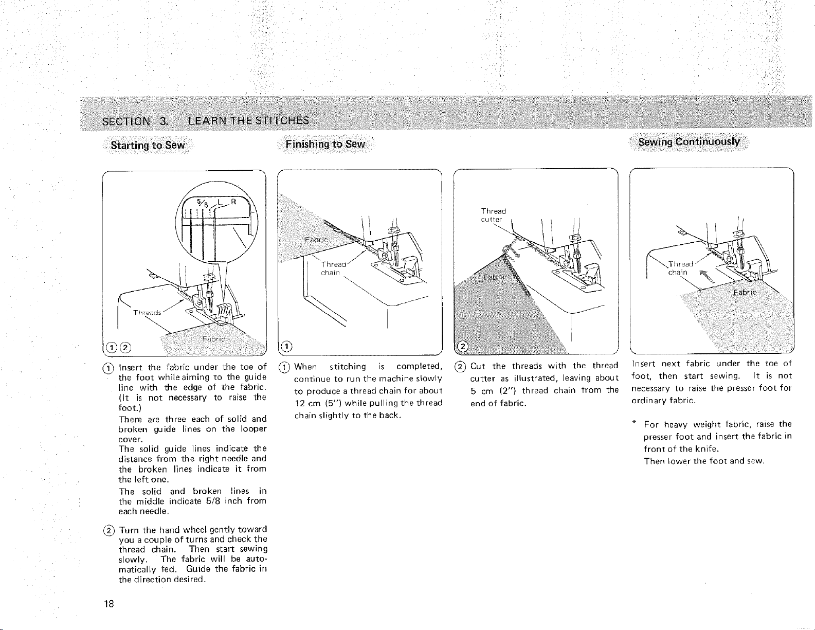
(]_ Insert the fabric under the toe of
the foot whileaiming to the guide
line with the edge of the fabric.
(It is not necessary to _aise the
foot.)
There are three each of solid and
broken guide lines on the looper
cover.
The solid guide lines indicate the
distance from the right qeedle ana
the broken lines indicate it from
the left one.
The solid and broken lines in
the middle indicate 5/8 inch from
each needle.
(2_ Turn the hand wheel gently toward
you a couple of turns and check the
thread chain. Then start sewing
slowly. The fabric wil be auto-
matically fed. Guide the fabric in
the direction desired.
18
®
(]]) When
stitching is completed,
continue to run the machine slowly
to produce a thread chain for about
12 cm (5") while pulling the thread
chain slightly to the back.
Threaa
CU[Ter
(_ Cut the threads with the thread
cutter as illustrated, leaving about
5 cm 12") tnreaa chain from the
end of fabric.
cnaln
Insert next fabric under the toe of
foot, then start sewing. It is not
necessary to raise the oresser foot for
ordinary fabric.
For heavy weight fabric, raise the
presser foot and insert the fabric n
front of the knife.
Then bower the foot and sew
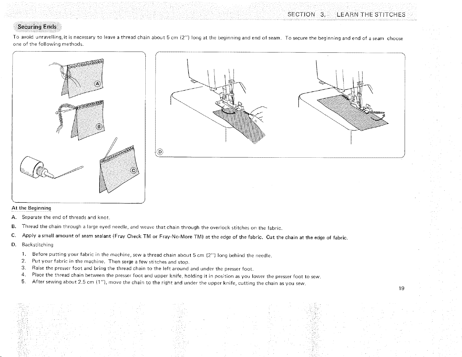
Toavoidunravelling,it isnecessaryto leaveathreadchainabout5col (2")longatthebegmningandendofseam.Tosecurethebeginningandendofaseamchoose
oneofthefollowingmethods.
At theBeginning
A. Separa£etheenaofthreadsandKnoT.
B. Threadthechainthroughalargeevedneedle,andweavethatchainthroughtheoverrockstitchesonthefabric.
C. Applyasmallamountofseamsealant(FrayCheckTMorFray-No-MoreTM!attheeageofthefabric.Cutthechainattheeageoffabric.
D. Backstitching
1. Beforeouttmgyourfabric;_themachine,sewathreadchainabout5cm(2")longbehindtheneedle
2. Putyourfabricqthemacnme.Then_ergeafewstitchesandstou.
3. Raisethepresserfootantbringthethreadchaintotneleftarounaannundertheoresserfoot
4. Placethethreadchainoetweenthepresserfoc[ annupperknifeholdingIt innositionasyoulowerthepresserfoottosew.
5. AftersewmgaDout2.5cm(l"),movethechairltotherlghtandunaertneupperknifecuttingthechairasyousew
19
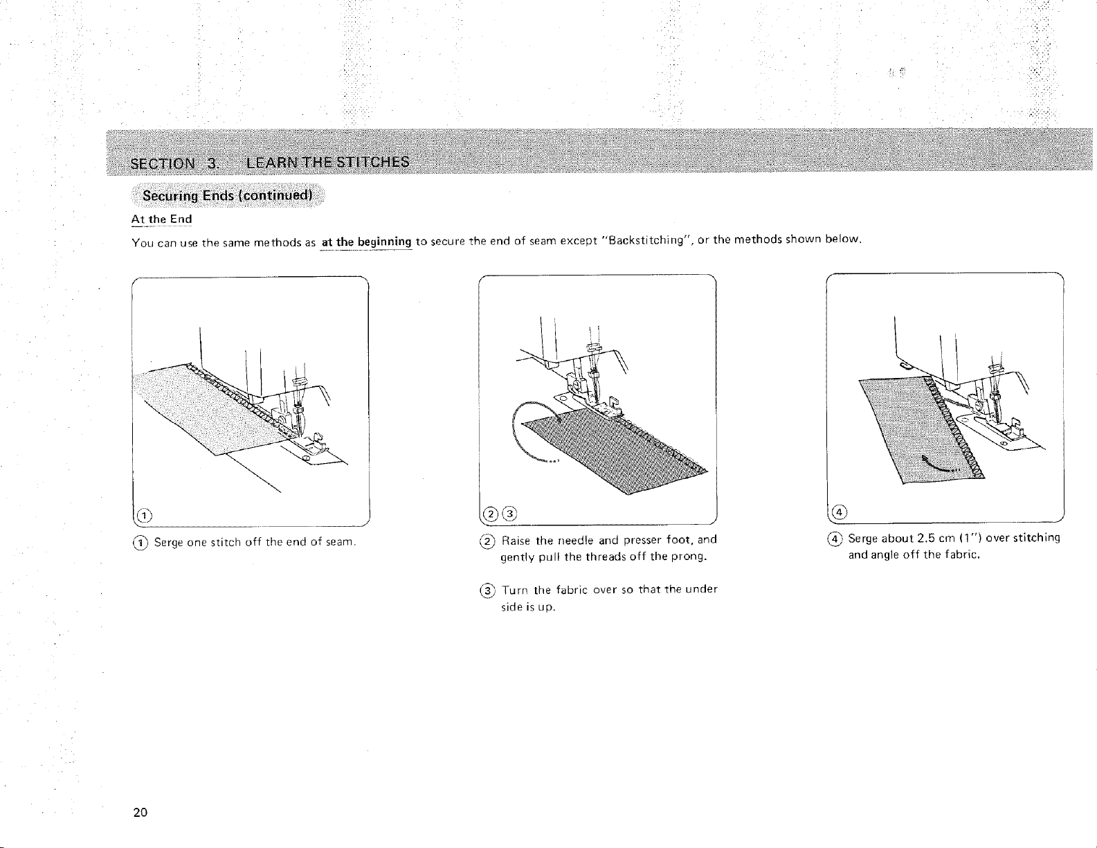
Securing Ends (Continued)
At the End
You can use ;he same methods as at the beginning _ to secure the eno of seam except "'Backsttch'ng ', or the methods shown below.
_) Serge one stitch off tile end of seam,
"_ Raise the needle and presser foot, and
gently pull the threads off the prong.
Serge about 2.5 cm (1 ") over stitching
and angle off the fabric.
(,_ Turn the fabric over so that the under
side is up.
2O
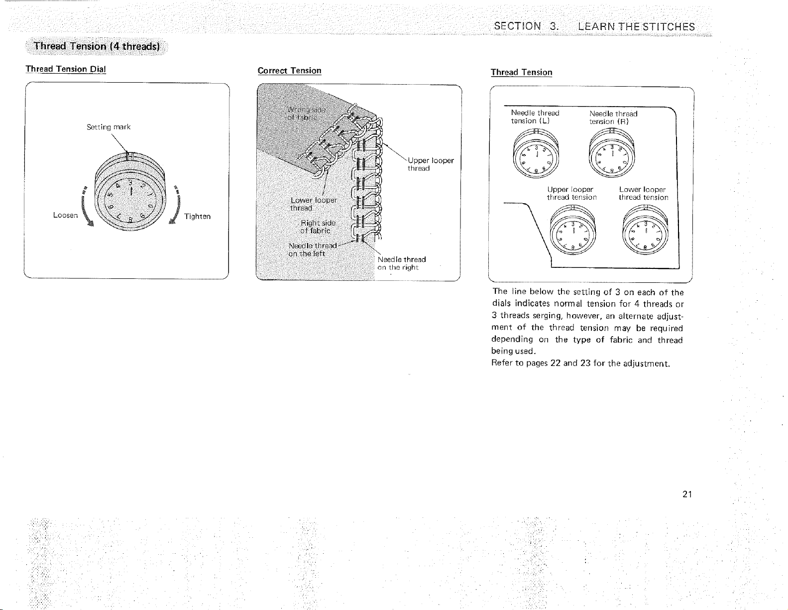
Thread Tension (4 threads)
Thread Tension Dial
f
Loosen
Setting mark
\
\
Tighten
Correct Tension
looper
[Rreao
\
Need le thread
on the right
SECTION 3. LEARN THE STITCHES
Thread Tension
Needle tt__eaa Needle thread
tension L) tension (R)
upper ooper Lower looper
thread tension thread tension
The line below the setting of 3 on each of the
dials indicates normal tension for 4 thread_ or
3 threads serging, however, an alternate adjust-
ment of the thread tension may be required
depending on the type of fabric and thread
being used.
Refer to 3ages 22 and 23 for the adjustment.
21
i.,,
•i¸_':::L
.!::71"i
,/ 2'
?:, ::i:• •
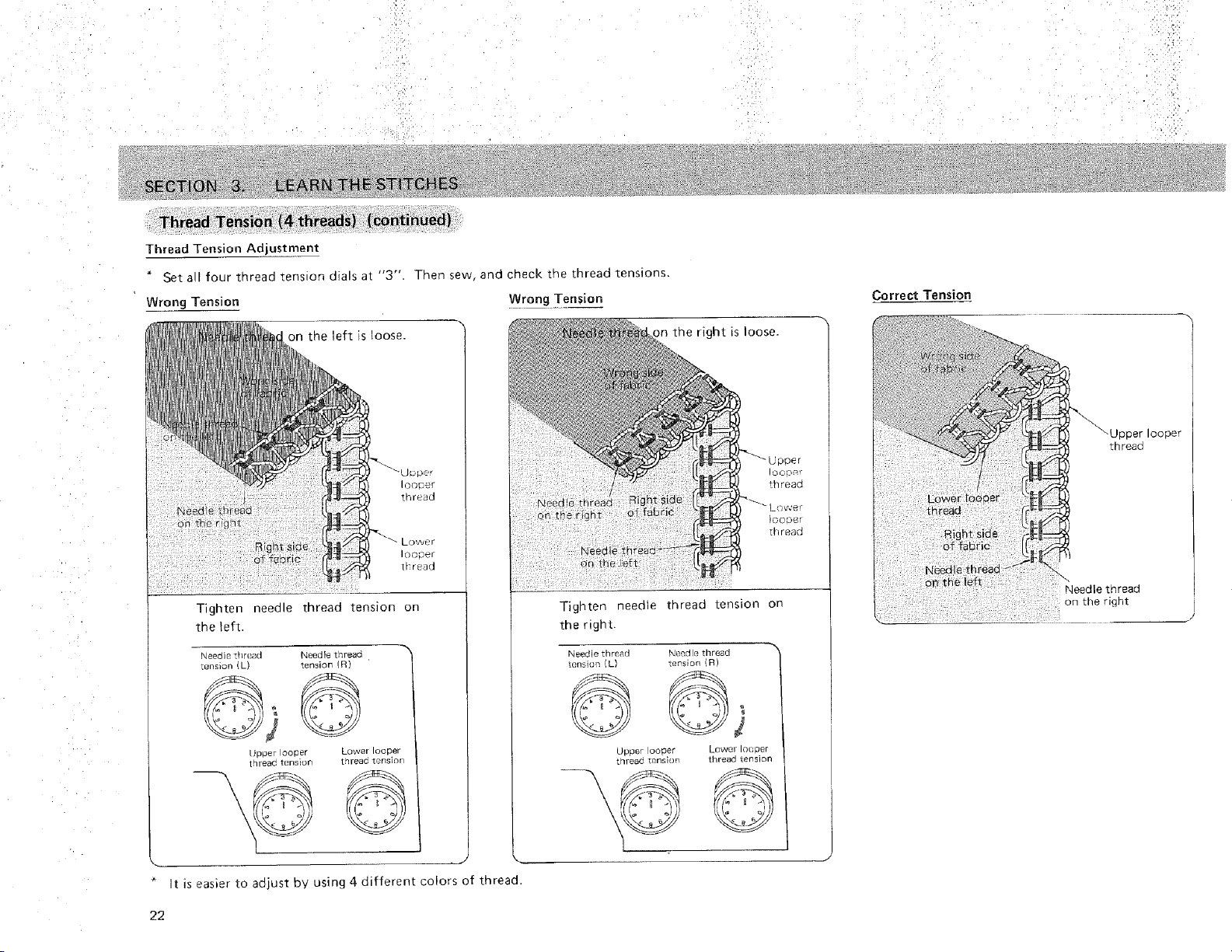
Thread Tension (_ threadS) '('continUed)
Thre ad Tension Adjustment
" Set all four thread tens on dials at "3". Then sew, and check the thread tensions.
Wrong Tension Wrong Tension
on he left is _oose.
Right alae
o_ fabric
iQocer
thr_'ao
Lowur
IC)Go_r
ir'r_ao
Tighten needle thread tension on
the left.
P,eed e :nrea(] "Jeedle tnreaa
÷ens_on _L} tension _
JDoer oo_er Lower looper
tqreac tensEun tnreac tonsior
right is loose.
Tign£en needle thread £ension on
the right.
LOW€J/ IOO Der
_nreaa tenslor
©
t is easier to adjust bv using 4 different colors of thread.
Correct Tension
thread
Needle thread
on the right
looper
22
SECTION 3. LEARN THE STITCHES
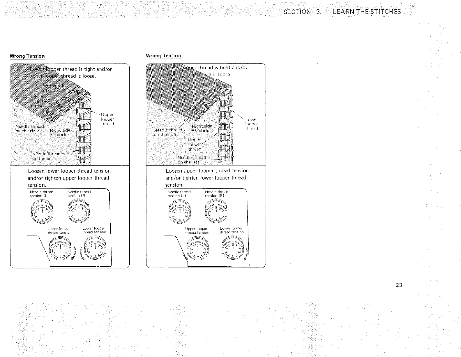
Wrong Tension
)er thread is tignT and/or
reao is loose.
)oDer
t[_r oL_u
Loosen ower Ioooer thread tension
andfor tignten upper looper thread
tension.
Needle thread Needle thread
ml/siorl IL tension (R:
I_{: :) )}
uoper n(iDc{r Lower looper
1 lreac teRsioP Tnreaa lP-ns el
1
Wrong Ten_ion
r thread is tight ari!!or
is loose.
Lower
iooDl'r
t "] r ._.8 C]
Loosen upper looper tnread tension
ana or tighten lower ooDer [nreau
tension.
Needle thread Ncea ts [riraa{1
lnHSiUr ,6 tension o_
Upper ,COD_! Lower IOODeT
1-1reao teRsEon [nrean T_zns el
23
Threading the Machine (3 threads); Wide/Narrow Stitch
_d;ii_i!,
o_ h _;
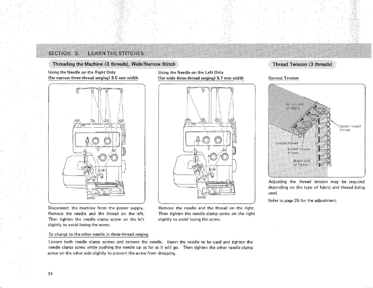
Using the Needle on the Right Only
(for narrow three-thread serging) 3.5 mm width
F
Using the Needle on the Left Only
(for wide three-thread serging) 5.7 mm width
f
Disconnect the machine from the power supply.
Remove the needle and the thread on the left.
Then tighten the needle clamp screw on the left
slightly to avoid losing the screw.
Remove the needle and the thread on the right.
Then tighten the needle clamp screw on the right
slightly to avoid losing the screw.
To change to the other needle in three-thread serging
Loosen both needle clamp screws and remove the needle. Insert the needle to be used and tighten the
needle clamp screw while pushing the needle up as far as it will go. Then tighten the other needle clamp
screw on the other side slightly to prevent the screw from dropping.
Correct Tension
Adjusting the thread tension
thread
may be required
depending on the type of fabric and thread being
used.
Relier to page 25 for the adjustment.
24
SECTION 3. LEARN THESTnTCHES
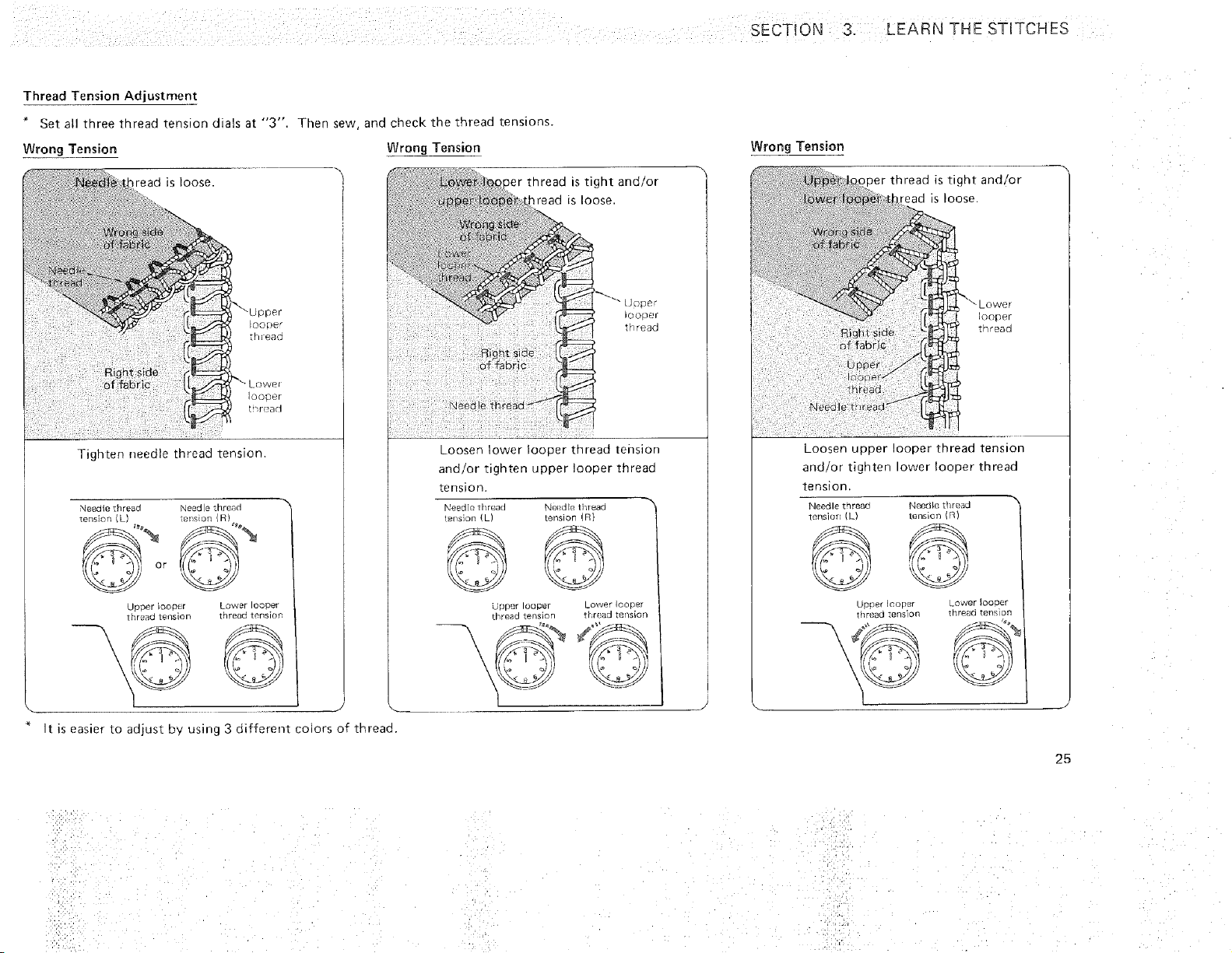
Thread Tension Adjustment
* Set all mree Tnreao tension d_als at "3", Ther sew and check the _nreaa tensions.
Wrong Tension Wrong Tension
Tighten needle thread tension.
"qeea_e thread Neec e _nreae
tensicn [L 'rmsi_n [4
mreao is tight and/or
lread is loose
jpDer EonBtr Lower looper
tnr,_au tension lr "cad tensioz
\.
\ ,((: _ :));
I
Right siae
o_ fabric
J D,[3e*
OODU/
thread
Needle thread "_:"
Loosen lower looper thread tension
aria or tighten upper looper thread
tension.
Need _.Trlrga{] %ee(Jlf_mr_ao \
BI1S]Or) LJ tension D
Jr;p_r lOaDer Lower ICe 3er
r_r*eao _ension t/read tensicr
I
It is easier [o adjust bv using 3 different colors of thread,
Wrong Tension
,per thread is tight and/or
read is loose
ower
Loosen uDDer ooper thread tension
and/or tignten lower looper thread
tension
I leedle tqreao
tensiar: (L)
uDcer looper
trlreao :ens or
2_
NneO le tilt CaLl
tensic n (R)
Lower _ooDer
_nre_icl ,'.el s on
©
l
25
• ::i!£
'i
riijq
: 1:!111!,i:£¸¸
ql.dlb
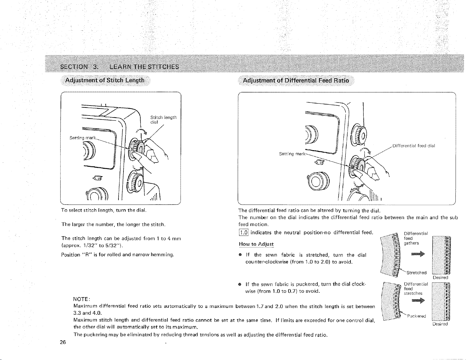
Adjustment of Stitch Length
f
Setting marK_
)
Stitch length
dial
/
_ J
To select stitch length, turn the dial.
The larger the number, the longer the stitch.
The stitch ength can be adjusteo from 1 to 4 mm
(approx. 1/32" to 5/32'q.
Position "R" is for rolled and narrow hemming.
Setting
Differential feed dial
The differential feed ratio can be altered by turning the dial.
The number on the dial indicates the differential feed ratio between the main and the sub
Differentia!
feed
gathers
feed motion.
[] indicates the neutral position-no differential feed.
How to Adjust
e If the sewn fabric is stretched, turn the dial
counter-clockwise (from 1.0 to 2.0) to avoid.
26
® If the sewn fabric is puckered, turn the dial clock-
wise (from 1.0 to 0.7) to avoid.
NOTE:
Maximum differential feed ratio sets automatically to a maximum between 1.7 and 2.0 when the stitch length is set between
3.3 and 4.0.
Maximum stitch length and differential feed ratio cannot be set at the same time. If limits are exceeded for one control dial,
the other dial will automatically set to its maximum.
The puckering may be eliminated by reducing thread tensions as well as adjusting the differential feed ratio.
_ _. Differental
fe_d
stretches
c ored
Desired
Desired
Adjustment of Foot Pressure
To increase
/
aecrease
//
_Adjusting
screw
< Standard Setting Position >
Top of the machine
\
\
\
View from "'A'" \
\
"_A'"
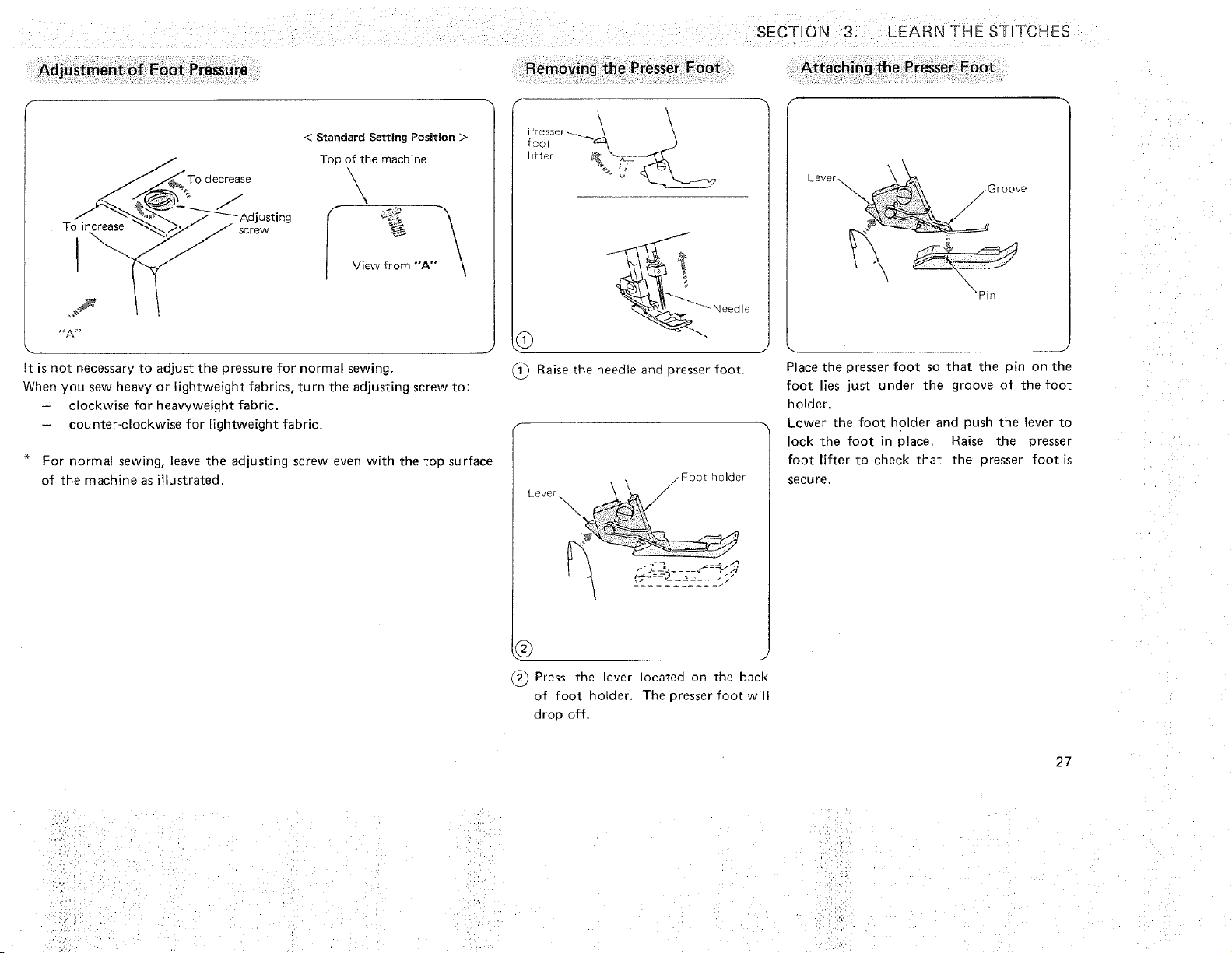
It is not necessary to adjust the pressure for normal sewing,
When you sew heavy or lightweight fabrics, turn the adjusting screw to:
- clockwise for heavyweight fabric.
counter-clockwise for lightweight fabric.
For normal sewing, leave the adjusting screw even with the top surface
of the machine as illustrated
Removing the Presser Foot
_- Neeale
Raise the needle and presser foot.
zFoat nolaer
Lever /
j
Press the lever Iocatea on the back
of foot holder The presser foot will
atop off
SECTION 3. LEARN THE STITCHES
Attaching the Presser Foot
kever_ \_,Groove
Place tne presser foot so that the pin on the
foot ies just under the groove of the foot
holder.
Lower the foot holder ana push the lever to
lock the foot in place Raise the presser
foot lifter to check that the oresser foot is
secure.
27
k"
Needle clamp screw
on the left
£3 screw
•on tne right
®
J
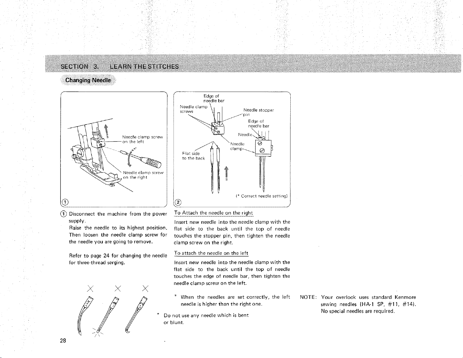
(_ Disconnect the machine from the power
supply.
Raise the needle to its highest position.
Then loosen the needle clamp screw for
the needle you are goin£ to remove.
Refer to page 24 for changing the needle
for three-thread serging.
28
Edge of
needle bar
_4eedle clamp \
screw_/J_'P mNeedleneea_eEdge\s[ooOerolbar
x Need[e.g,.
_Needle ! _
clamp-_
Flat siae
to the back
1
I * Correct needle setting]
To Attach the needle on the right
nsert new needle into the needle clamp with the
flat side to the back until the top of needle
touches the stopper pin, then tighten the needle
clamp screw on the right.
To attach the needle on the eft
Insert new needle into the needle clamp with the
flat side to the back until the top of needle
touches the edge of needle bar. then tighten the
needle clamp screw on the left.
When the needles are set correctly, tne left
needle is higher than the right one.
Do not use any needle which is bent
or blunt•
NOTE: Your overlock uses standard Kenmore
sewing needles (HA-1 SP, #11, #14).
No special needles are required.
SECTION 3. LEARN THESTNTCHES
To Disengage the Upper Knife
\'\
_17 t
knife \ / \_ I
knob _ ,7, / "/ _'-_-Opperl
I"
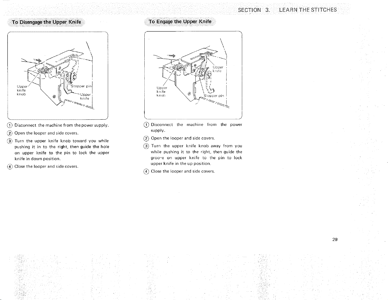
1_ Disconnect the machine from the Dower supply.
2_ Ooen the looper and side covers.
Turn tne upper knife knoo toward you while
pushing it in to the right, then guide the hole
on upper knife to the pin to lock the upper
knife in down position.
_ Close _ne looper and side covers.
To Engage the Upper Knife
\
" _.._
_ Disconnect the machine from the oower
supply,
(_ Open the looper and side covers.
(_) Turn the upper knife knob awav from you
while pushing It to the right, ther guide the
groo',e on upper knife to tne Din tO lock
upper knife m the up position.
_ Close the looper and side covers.
29
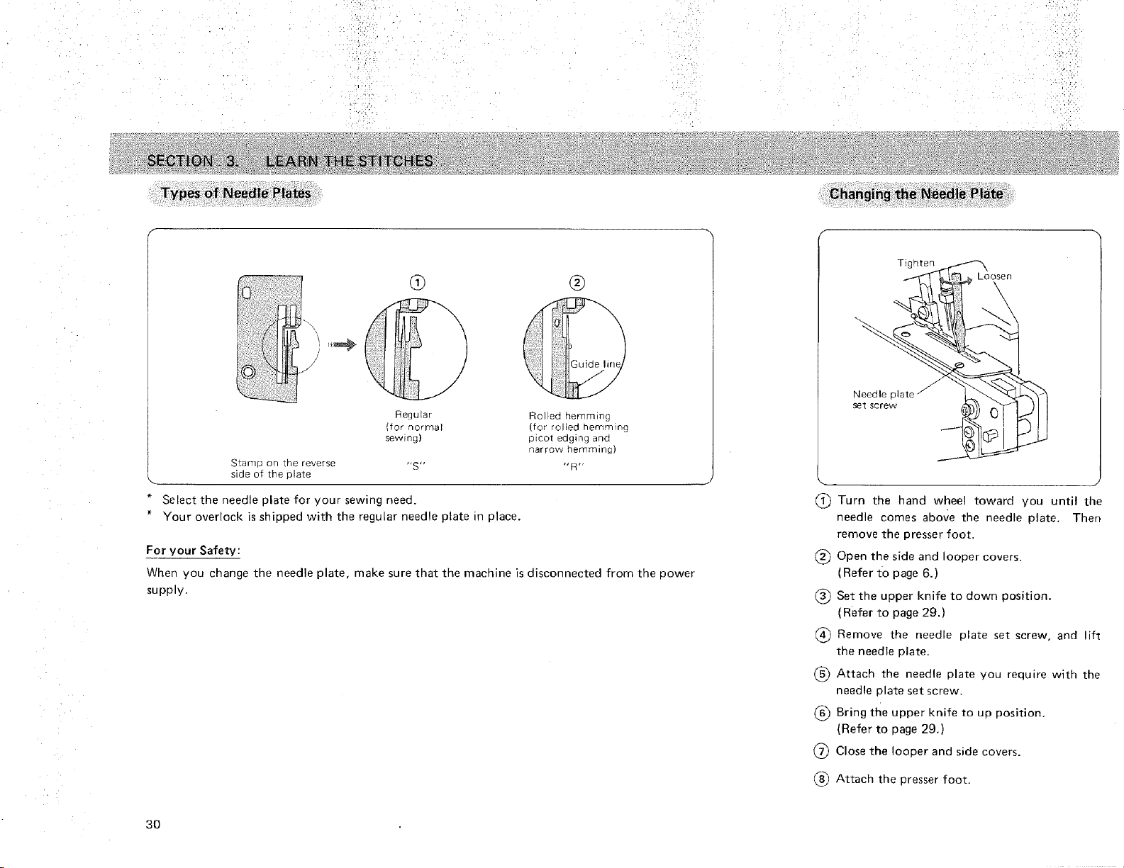
Stamp on the reverse "S"
side of the plate
* Select the needle plate for your sewing need.
* Your overlock is shipped with the regular needle plate in place.
Regular Rolled hemming
(for normal (for rolled herrlqfing
sewing) picot edging and
narrow hemming)
"R"
For your Safety:
When you change the needle plate, make sure that the machine is disconnected from the power
supply.
3O
Changing the Needle Plate
Tighten
Loosen
Needle pl_
set screw
(_ Turn the hand wheel toward you until the
needle comes above the needle plate, Then
remove the presser foot,
(_ Open the side and looper covers.
(Refer to page 6.)
(_ Set the upper knife to down position.
( Refer to page 29.)
Remove the needle plate set screw, and lift
the needle plate.
(_) Attach the needle plate you require with the
needle plate set screw,
(_) Bring the upper knife to up position.
(Refer to page 29.)
(_ Close the looper and side covers.
Attach the presser foot.
SECTPON 3. LEARN THE STITCHES
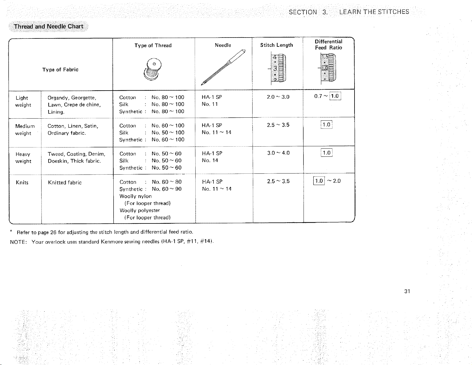
Thread and Needle Chart
Type of Fabric
Light Organdy, Georgette,
weight Lawn, Crepe de chine,
Lining.
Medium Cotton, Linen, Satin,
weight Ordinary fabric.
Heavy i Tweed, Coating, Denim,
weight Doeskin, Thick fabric.
Knits Knitted fabric
Type of Thread
Cotton :
Silk
Synthetic :
Cotton :
Silk
Synthetic :
Cotton : No. 50 _ 60
Silk : No. 50_60
Synthetic : No. 50_ 60
Cotton : No. 60_ 80
Synthetic : No. 60_90
Woolly nylon
(For looper thread)
Woolly polyester
(For looper thread)
No. 80 _ 100
No. 80 _ 100
No. 80 _ t00
No. 60_ 100
No. 50 _ 100
No. 60 _ 100
* Refer to 3age 26 for adjusting the stitch length and differential feed ratio.
NOTE: Your overtock uses standard Kenmore sewing needles (HA-1 SP, ,#I 1. #14).
NeedJe
f
HA-1 SP
No. 11
HA-1 SP
No. 11 _ 14
HA-1 SP
No. 14
HA-1 SP
No. 11 _14
Stitch Length
2.0 _ 3.0
2.5 _ 3.5
3.0 _ 4.0
2,5 _ 3.5
I Differential
Feed Ratio
]
0.7 _ 1.0
_i_ 2,0
31
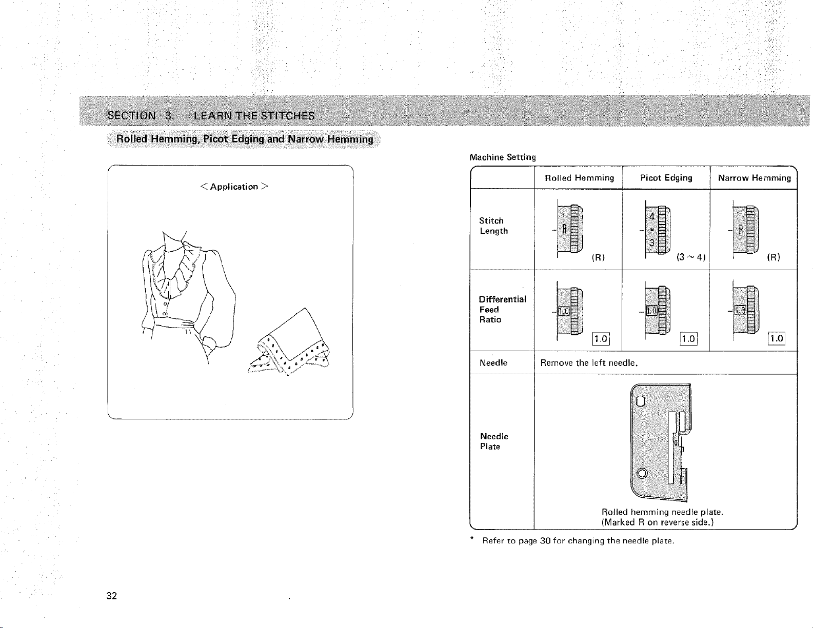
Rolled Hemmingi Picot Edging and Narrow Hemming
32
< Application _>
Machine Settin,
Rolled Hemming Picot Edging Narrow Hemming
Stitch
Length
Differential
Feed
Ratio
(R)
Needle Remove the left needle.
Needle
Plate
i il;iii!
(3 _4)
Z_
(R)
[]
Rolled hemming needle plate.
(Marked R on reverse side.)
Refer to page 30 for changing the needle plate.
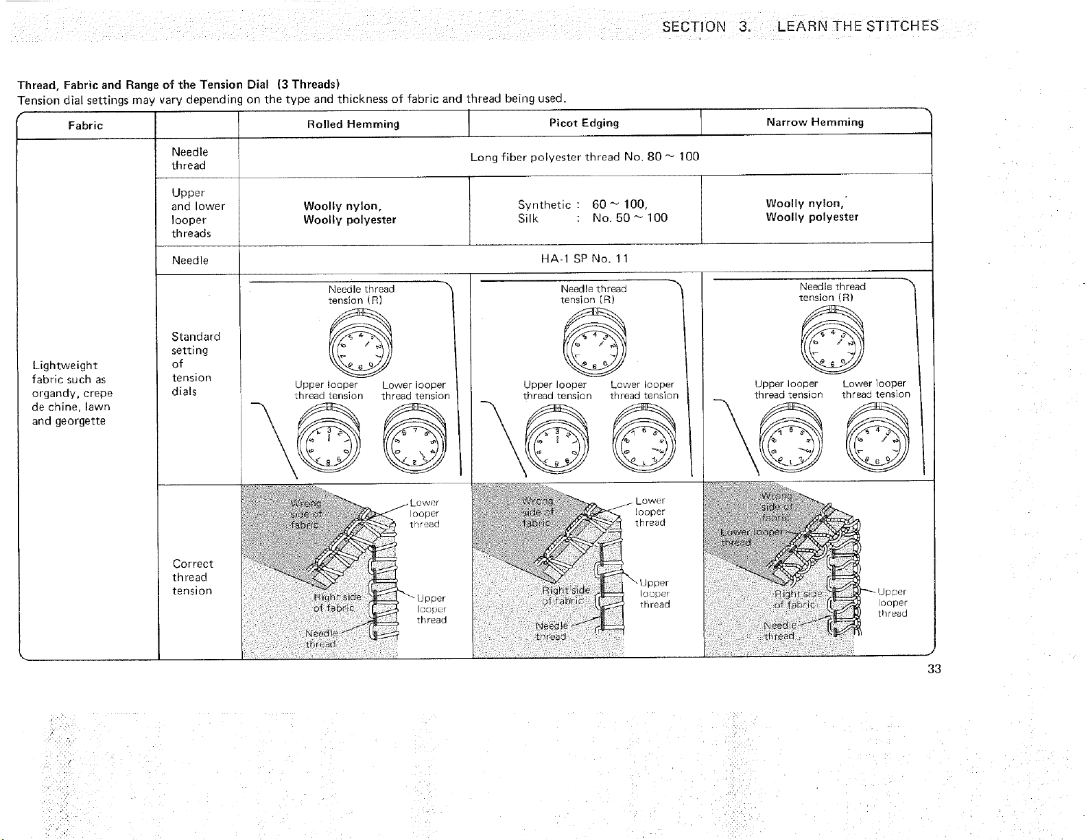
SECTION 3, LEARN THE STITCHES
Thread, Fabric and Range of the Tension Dial (3 Threads)
Tension dial settings may vary depending on _ne type and thickness of fabric and thread being used.
Fabric Roiled Hemming Picot Edging Narrow Hemming
Needle Long fiber polyester thread No. 80 _ 100
thread
Upper
and lower Woolly nylon, Synthetic : 60 _ 100, Woolly nylon,"
looper Woolly polyester Silk : No. 50 _ 100 Woolly polyester
threads
Needle HA-1 SP No. 11
Lightweight
fabric such as
organdy, crepe
de chine, lawn
and georgette
Standard
setting
of
tension
dials
Correct
thread
tension
Needle thread
tension (R)
Upper looper
Lhread tension
Lower looper
thread tension
Needle thread _'_
tension (R)
@ ,
Upper looper Lower looper
thread tension thread tension
Needle thread
tension (R)
@
Upper looper
thread _ension
/ Lovver
._ looper
hread
Upper
-.,t loouer
thread
Lower looper
thread tension
!
#'_-- Upper
l ooper
) thread
33
,i
• • !i:¸ i!i
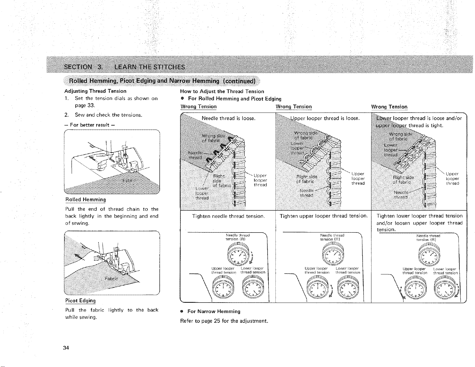
Adjusting Thread Tension
1. Set the tension dials as shown on
page 33.
2. Sew and check the tensions.
-- For better result --
/-
f
RoUled Hemming
Pull the end of thread chain to the
hack lightly in the beginning and end
of sewing.
Picot Edging
Pull the fabric ightlv to the back
while sewing.
How to Adjust the Thread Tension
o For Roiled Hemming and Picot Edging
Wrong Tension Wrong Tension Wrong Tension
Needle thread is loose. 3er looper thread is loose. is loose and
looper
thread
Tighten needle thread tension.
Needle £h/ead _'_
_ensIOF R)
uloDer looper Lower looper
[bread tension _l_reaG _en_of3
I
Tighten upper looper thread tension.
Needle thread
tension (R)
©
Upper looper Lower looper
thread tensiorl thread tension
Tighten lower looper thread tension
and/or loosen upper looper thread
tension.
Needle thread
tension (R)
@
Upper looper Lower looper
thread tension thread tension
_ j
® For Narrow Hemming
Refer to page 25 for the adjustment.
34
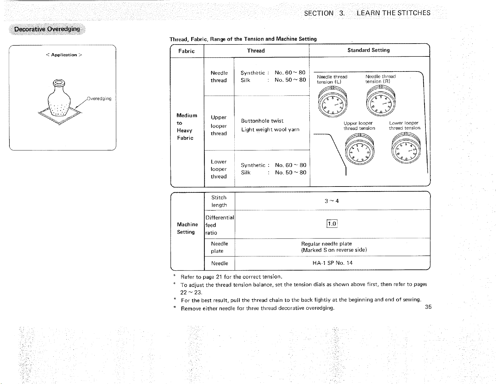
SECTION 3. LEARN THE STITCHES
< Application >
Thread, Fabric, Range of the Tension and Machine Setting
Fabric
Medium
to
Heavy
Fabric
Thread Standard Setting
Needle
thread
Synthetic : No. 60_80
Silk : No. 50_80
Upper Buttonhole twist
looper
thread Light weight wool yarn
Needle thread Needle thread
tension (L) tension (R)
Lower
Synthetic : No, 60_80
looper Silk : No. 50 _ 80
thread
Stitch 3 _ 4
length
Differential
Machine feed [_q
Setting ratio
Needle Regular needle plate
plate _Marked S on reverse side)
Needle HA-1 SP No. 14
Upper looper Lower !ooper
thread tension thread tension
Refer to page 21 for the correct tension
To adjust tiqe thread tension balance, set the tension dials as shown above first, then refer to pages
22 _ 23.
For the best result, pull the thread chain to tiqe back lightly at the beginning and end of sewing,
Remove either needle for three thread decorative overedging. 35
=.
'!:?_
36
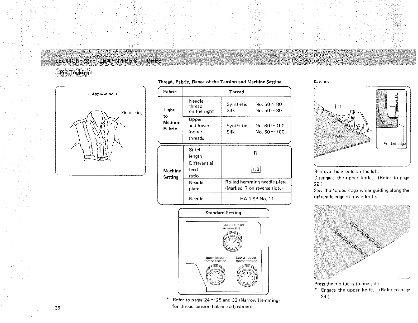
< Application _>
Pin tucking
Thread, Fabric, Range of the Tension and Machine Setting
Fabric Thread
Light
to
Medium
Fabric
Needle
thread Synthetic . No. 60_80
on the right Silk : No. 50-- 80
Upper
and lower Synthetic : No. 60-- 100
looper Silk : No. 50_ 100
threads
J
Stitch
R
length
Differential
Machine feed
Setting ratio
Needle Rolled hemming needle plate.
plate (Marked R on reverse sideJ
Needle HA-1 SP No. 11
J
-%
Standard Setting
Need le thread
tension _l
©
ugoer Looper Lower _o( oer
thread tanslon thread tans'nn
Refer to pages 24 _ 25 and 33 (Narrow Hemming)
for thread tension balance adjustment,
Sewing
Fulded cage
Remove the needle on the left.
Disengage the upper knife. (Refer [o page
29 t
Sew the folded edge while guiding along the
right side eage of ower knife.
i,
J
Press the pin tucks to One side.
* Engage the upper knife. (Refer to page
29.)
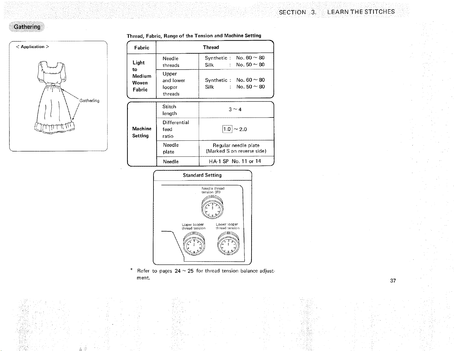
SECTION 3. LEARN THE STITCHES
< Application >
_/Gathering
Thread, Fabric, Range of the Tension and Machine Setting
Fabric Thread
Needle Synthetic : No. 60 _ 80
Light threads Silk No. 50 _ 80
to
Medium Upper
Woven and lower Synthetic No. 60 _ 80
Fabric looper Silk No. 50 _ 80
threads
Stitch
3_4
length
Differential
Machine
feed II.oj- 2.0
Setting ratio
Needle Regular needle nlate
olate (Marked S on reverse side)
Needle HA-1 SP No, 11 or 14
J
Standard Setting
Needle [nreaa
tension [R)
uDDer looper Lower Doper
tnreaa %snslon Trlreaa tension
Refer to pages 24 _ 25 for thread tension balance adjust-
ment.
37
H
;F ,_¸
%ii!!il
i!ii _ii__,
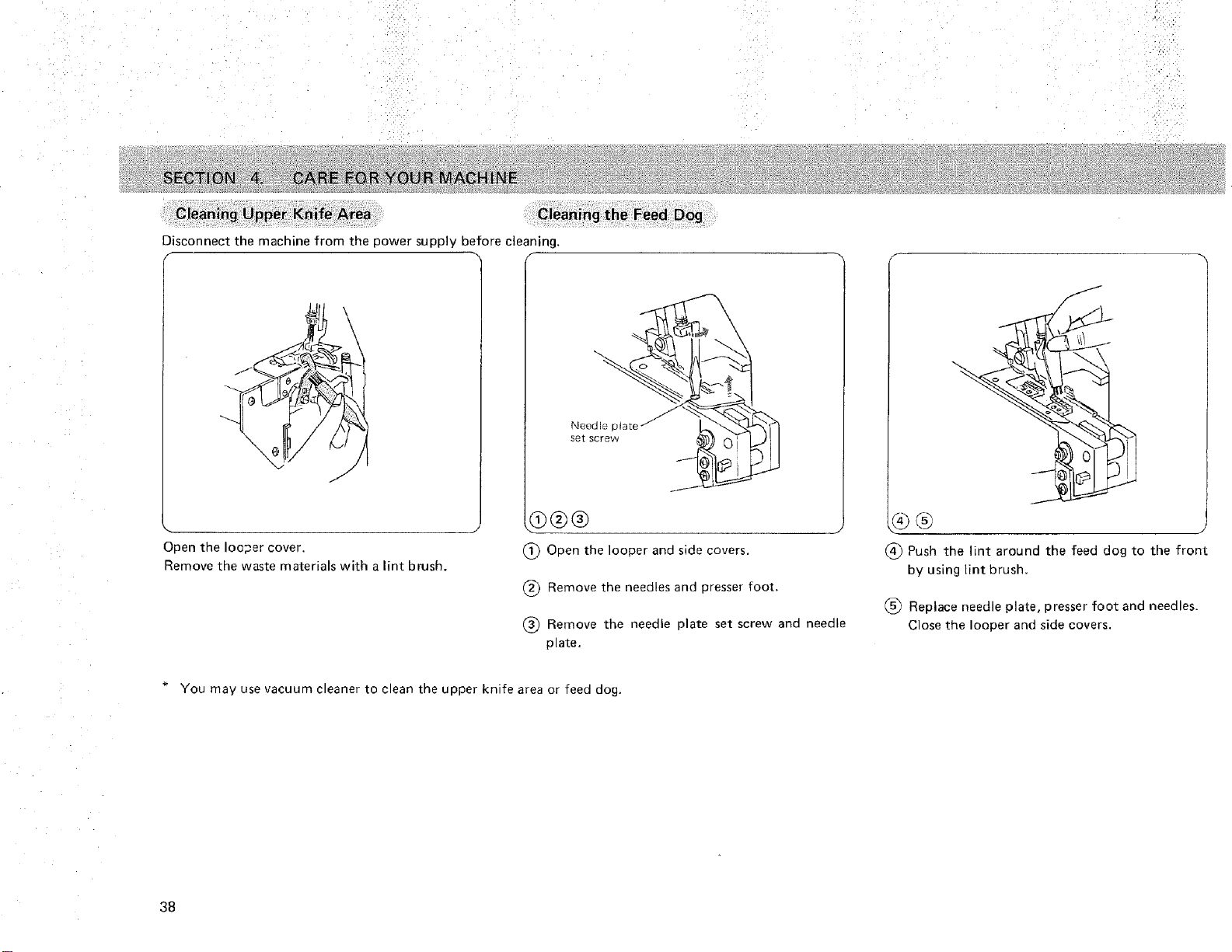
Cleaning,the Feed Dog
Disconnect the machine from the power supply before cleaning,
/
Open the looper cover.
Remove the waste materials with a lint brush.
Needle plate
set screw
(_ Open the looper and side covers.
(_ Remove the needles and presser foot.
® Remove the needle plate set screw and needle
plate.
I
L_j
Push the lint around the feed dog to the front
by using tint brush.
Replace needle plate, presser foot and needles.
Close the looper and side covers.
* You may use vacuum cleaner to clean the upper knife area or feed dog.
38
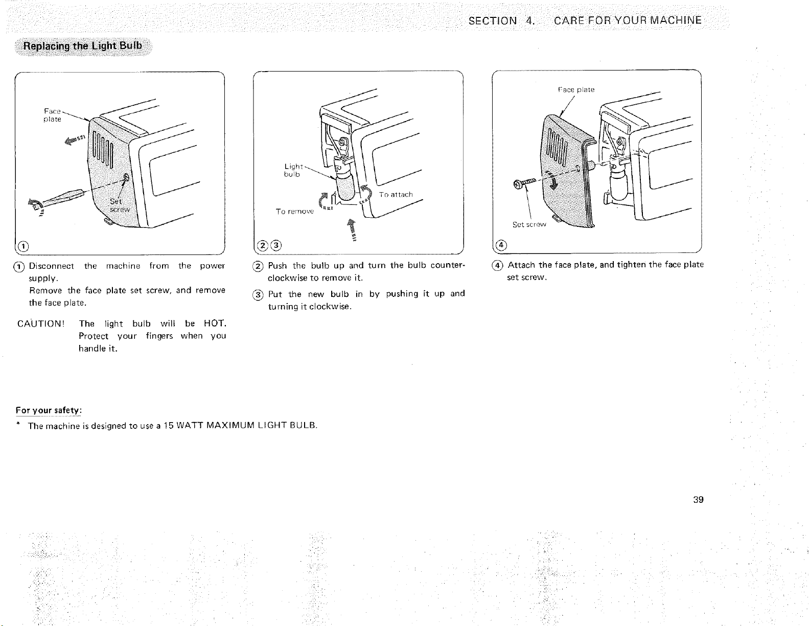
Replacing the Light Bulb
clare
9
Disconnecl the machine from the power
supply.
Remove the face plate set screw, and remove
the face ola_e.
CAUTION! The light bulb will be HOT.
Protect your fingers when you
handle it.
T ) remove
i
(_ Push the bulb up and turn the bulb counter-
clockwise to remove "Lt.
Put tne new bulb in by pushing it up and
turning it clockwise.
Attach the face plate, and tighten the face plate
set screw.
For your safety:
" The machine is designed to use a 15 WATT MAXIMUM LIGHT BULB.
39
• iii!iiii:!
• '_ ,b
,;,2"_:
.... ',i _ ,_4•
• i•¸,¸4¸
. _,,i: _ ¸' •
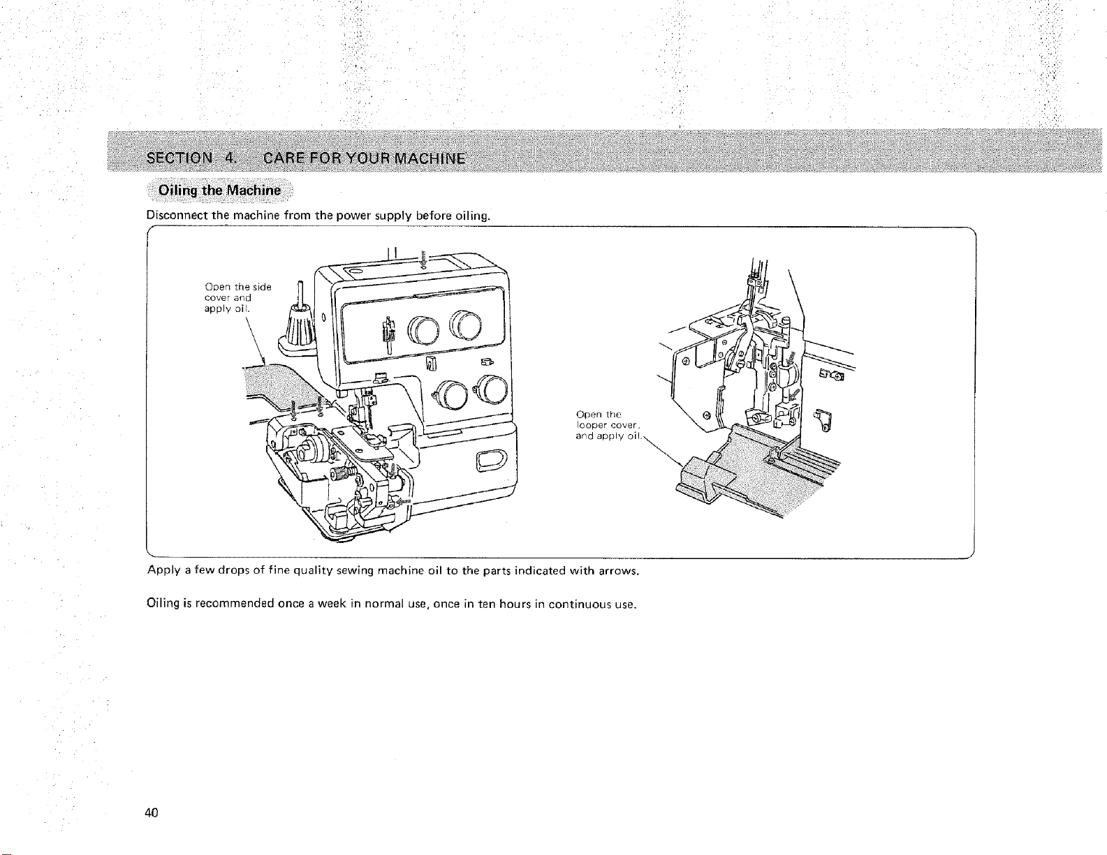
Disconnect the machine from the power supply before oiling.
Open the side
cover and
apply oil.
\
Open the
looper cover,
and apply
Apply a few drops of fine quality sewing machine oil to the parts indicated with arrows.
Oiling is recommended once a week in normal use, once in ten hours in continuous use.
40
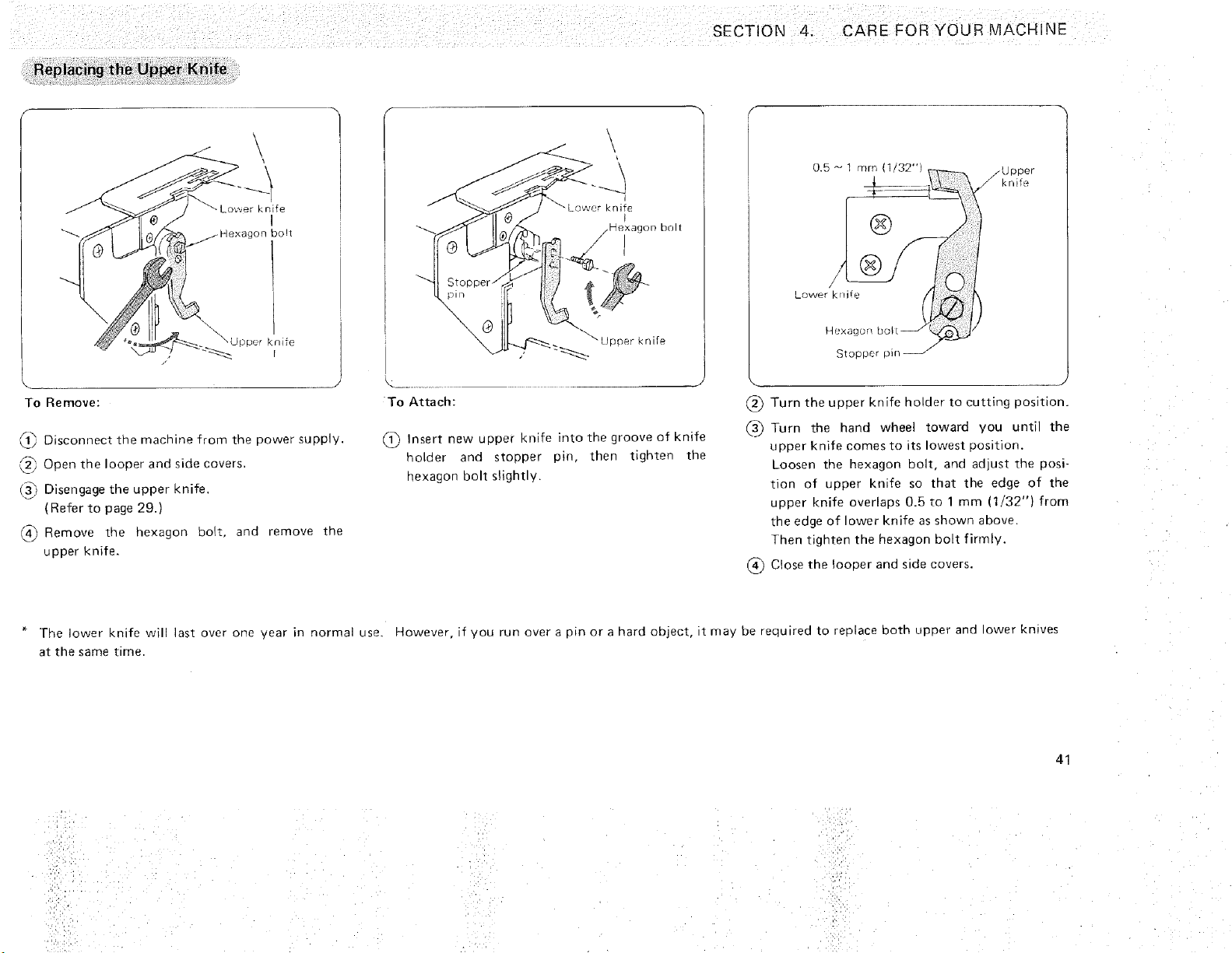
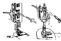
Replacing the Upper Knife
SECTION 4. CARE FOR YOUR MACHINE
To Remove:
_'_ Disconnect tne machine from the Dower suoply.
_" Open tne looper and side covers.
(_ Disengage the upper knife
(Refer to page 29.)
_4_ Remove the hexagon Do_t. and remove the
upper knife.
/ \
KnITE
,_exacl£)n DOlt
/
To Attach:
@
nsert new upper knife into the groove of knife
nolder and stopper pin, then tighten the
nexagon bolt slightly.
..Upper
knife
Lower krlUe
Turn the upper knife holder to cutting position.
Turn the hand wheel toward you until the
upper knife comes to its lowest oosition
Loosen me hexagon bolt, and adjusl the posi-
tion of upper knife so that the edge of the
upper knife overlaps 0.5 to 1 mm (1/32") from
the edge of lower knife as showr above.
Then tighten the hexagon bolt firmly.
(_ Close the looper and side covers.
The lower knife will last over one year in normal use, However, if you run overa oinorahard object, t mav be required to replace both upper and ower kn_ves
at the same [ me
41
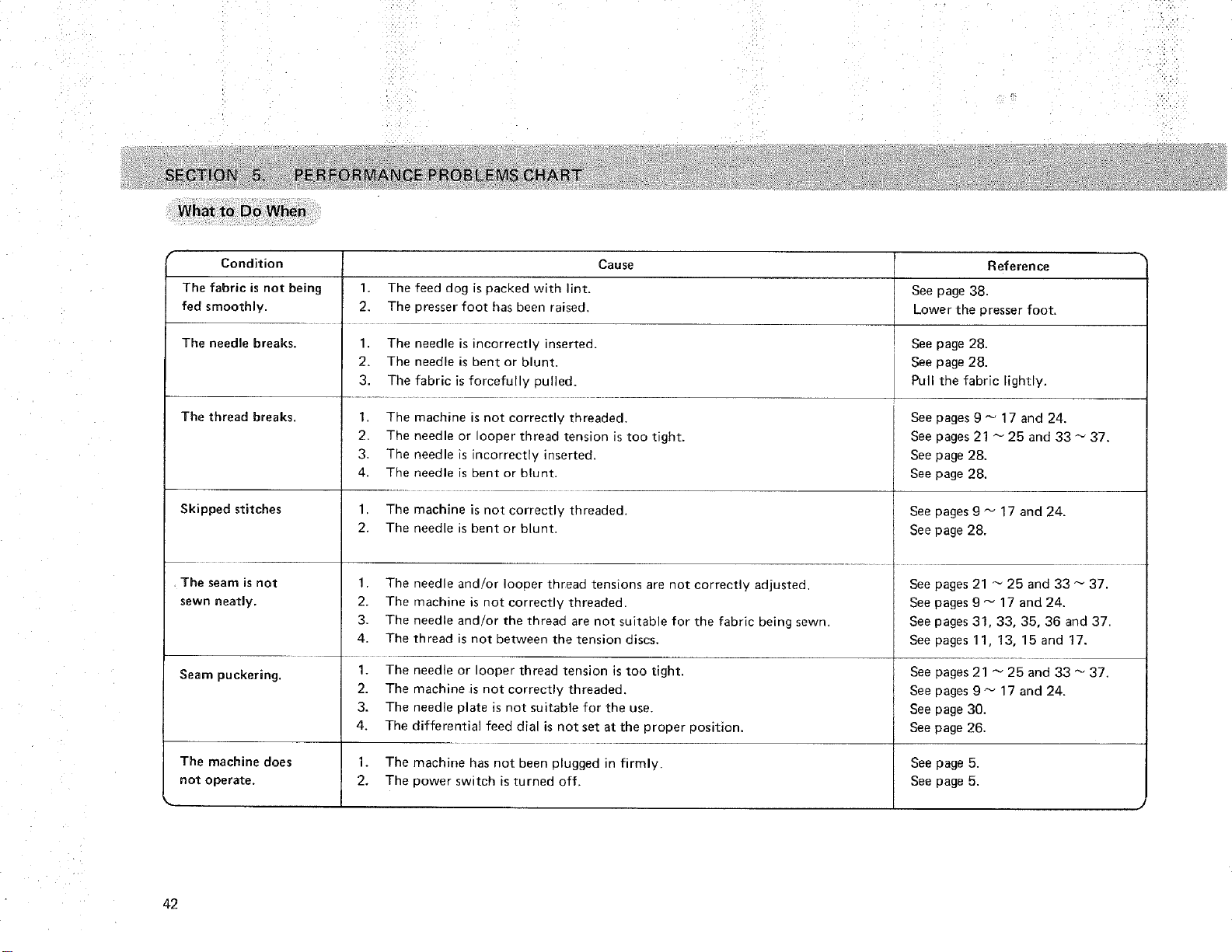
What to Do When
Condition
The fabric is not being
fed smoothly.
The needle breaks.
The thread breaks.
Skipped stitches
. The seam is not
sewn neatay.
Seam puckering.
Cause
1. The feed dog is packed with lint.
2, The presser foot has been raised.
1. The needle is incorrectly inserted.
2. The needle is bent or blunt.
3. The fabric is forcefully pulled.
1. The machine is not correctly threaded.
2. The needle or looper thread tension is too tight.
3. The needle is incorrectly inserted.
4. The needle is bent or blunt.
1. The machine is not correctly threaded.
2. The needle is bent or blunt.
1. The needle and!or looper thread tensions are not correctly adjusted.
2. The machine is not correctly threaded.
3. The needle and/or the thread are not suitable for the fabric being sewn.
4. The thread is not between the tension discs,
1. The needle or looper thread tension is too tight.
2. The machine is not correctly threaded.
3. The needle plate is not suitable for the use.
4, The differential feed dial is not set at the proper position.
Reference
See page 38.
Lower the presser foot.
See page 28.
See page 28.
Pull the fabric lightly.
See pages 9 _ 17 and 24.
See pages 21 _ 25 and 33 _ 37.
See page 28.
See page 28.
See pages g _ 17 and 24.
See page 28.
See pages 21 _ 25 and 33 _ 37.
See pages 9 _ 17 and 24.
See pages 31, 33, 35, 36 and 37.
See pages 11, 13, 15 and 17.
See pages 21 _ 25 and 33 _ 37.
See pages 9 _ 17 and 24.
See page 30.
See page 26.
The machine does 1. The machine has not been plugged in firmly. See page 5.
not operate. 2, The power switch is turned off. See page 5.
k. •
42
PARTS LIST
!1
16
18
4
7
12
19
8
ic i
14
10
15
17
21 22
J
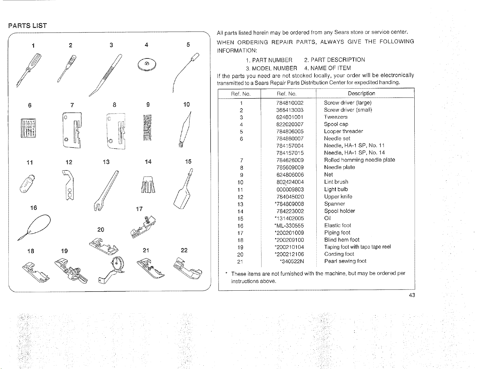
All parts listed herein may De oroereu from any Sears store or serwce center.
WHEN ORDERING REPAIR PARTS. ALWAYS GIVE THE FOLLOWING
NFORMATION:
1. PART NUMBER 2. PART DESCRIPTION
3. MODEL NUMBER 4 NAME OF TEM
If the carts you need are not s_ecked locally, your order wil be electronically
transmitted to a Sears Repair Parts Distribution Center for expedited handing.
_ef. No. qef No.
1 784810002
2 366413OO3
3 624801001
822020307
5 784806005
6 784860007
784157004
784157015
7 784626009
8 785609009
9 624806006
10 802424004
11 000009803
12 784045O2O
13 *784809008
14 784223002
15 *131402005
16 _ML-330555
17 *200201009
18 *200209100
19 *200210104
20 *200212106
21 _340522N
Description
Screw driver [large)
Screw driver (smalb
Tweezers
Spool cap
Looper threader
Needle set
Needle, HA-1 SP, No. 11
Needle. HA-" SP. No. 14
Rolled hemming needle plate
Needle olate
Net
Lint brush
Light bulb
Uoper knife
Spanner
Spool holder
Oil
Elastic foot
Piping fool
Blind hem foot
Taping foot with tape tape reel
Cording loot
Pear sewing foot
* These items are not furnished with the machine, but may be ordered per
instructions above.
43
i iii i
'i
7 •
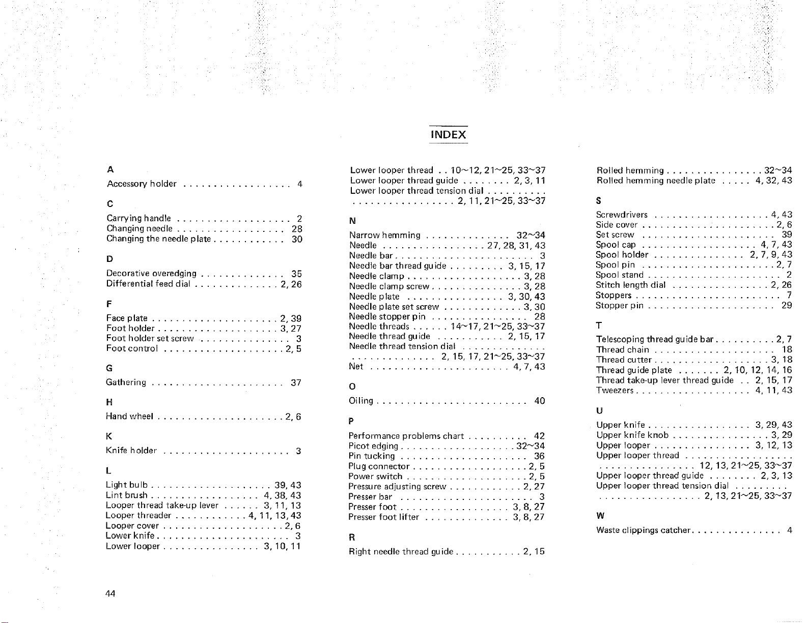
iNDEX-
A
Accessory holder ................. 4
C
Carrying handle ................... 2
Changing needle .................. 28
Changing the needle plate ............ 30
D
Decorative overedging ............. 35
Differential feed dial .............. 2, 26
Face plate ..................... 2, 39
Foot holder .................... 3.27
Foot holder set screw ............... 3
Foot control .................... 2, 5
G
Gathering ...................... 37
H
Hand wheel ..................... 2, 6
K
Knife holder ..................... 3
L
Light bulb .................... 3£ 43
Lint brush .................. 4, 38, 43
Looper thread take-ua lever ...... 3, 11, 13
Looper threader ............ 4, 11, 13,43
Looper cover ................... 2, 6
Lower knife ...................... 3
Lower looper ............... 3,10,11
Lower looper thread . . 10_12.21_25, 33_37
Lower looper thread guide ........ 2, 3, 11
Lower looper thread tension dial ..........
................. 2, 11,21_25, 33_37
N
Narrow hemming ............ 32_34
Needle ................. 27, 28, 31, 43
Needle bar ....................... 3
Needle bar thread guide ......... 3, 15, 17
Needle :lamp .................. 3, 28
Needle :lamp screw ............... 3, 28
Needte plate ............... 3,30,43
Needle plate set screw ............. 3, 30
Needle stopper pin ................ 28
Needle threads ...... 14_17, 21_25, 33_37
Needle thread guide .......... 2, 15, 17
Needle thread tension dial ..............
.............. 2. 15, 17, 21_25, 33_37
Net ....................... 4, 7, 43
o
Oiling ......................... 40
P
Performance problems chart ......... 42
Picot edging ................... 32_34
Pin tucking ..................... 36
Plug connector ................... 2, 5
Power switch .................... 2, 5
Pressure adjusting screw ............ 2.27
Presser bar ...................... 3
Presser foot .................. 3, 8, 27
Presser foot lifter .............. 3, 8, 27
R
Right needle thread guide ........... 2.15
Rolled hemming ................ 32_34
Rolled hemm ng needle plate ..... 4, 32.43
S
Screwdrivers ................... 4.43
Side cover ...................... 2, 6
Set screw ...................... 39
Spool cap .................. 4, 7, 43
Spool holder ............... 2, 7, 9, 43
Spool pin ..................... 2, 7
Spoo stand ...................... 2
Stitch length dia ............... 2, 26
Stoppers ........................ 7
Stopper pin .................... 29
T
Telescoping thread guide bar .......... 2, 7
Thread chain .................... 18
Thread cutter ................... 3, 18
Thread guide plate ....... 2, 10, 12. 14, 16
Thread take-up lever thread guide . . 2, 15. 17
Tweezers ................... 4. 11.43
U
Upper knife ................. 3.29, 43
Upper knife knob ................ 3.29
Upper looper ................ 3, 12, 13
Upper looper thread ..................
............... 12,13,21_25,33_37
Upper looper thread guide ........ 2, 3, 13
Upper looper thread tension dial .........
................. 2, 13, 21_25, 33_37
W
Waste clippings catcher ............... 4
44

MEMO
_ !iiii!i!__ __i,i_ •
_!ii_ii_• _,i_i _ _ •
_,?i_iii i _ i_ i, •
i_i_iii_i_i_ ii__
• ii_i_ _i

i i _,
_ _.iii!i:i¸
,!:i_iii!i:_i,
MEMO
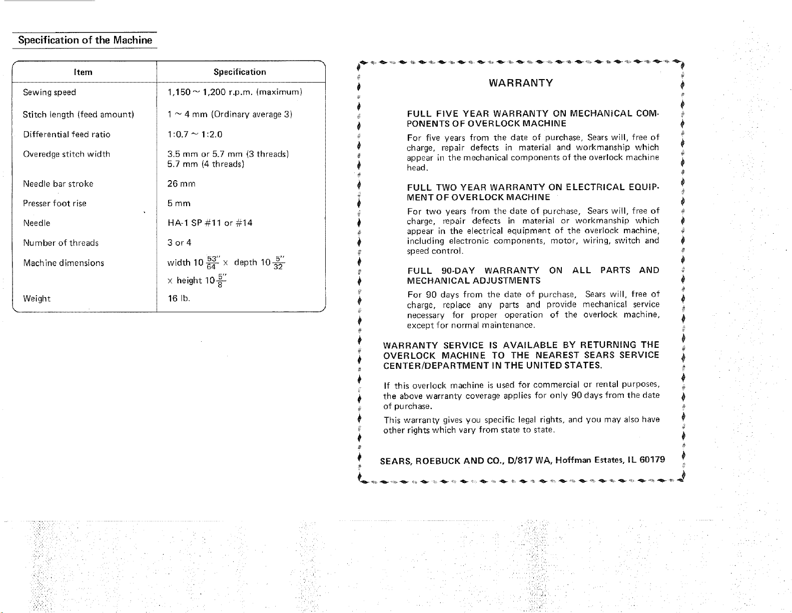
Specification of the Machine
r
Item
Sewin£ speed
Stitch ength (feed amountJ
Specification
1,150_ 1,200 r.p.m. {maximum;
1 _ 4 mm (Ordinary average 3)
Differential feed ratio
Overedge stitch width
Needle bar stroke
Presser foot rise
Needle
Number of threads
Machine dimensions
Weight
1:0.7 _ 1:2.0
3.5 mm or 5.7 mm t3 threads)
5.7 mm t4 threads)
26 mm
5mm
HA-1 SP#11or=14
3or4
53" deotl _ lOa@
width 10 -_- x
5"
x height 10_-
16 lb.
=
0
=-
0
_=
=
0
=-
#
WARRANTY
FULL FIVE YEAR WARRANTY ON MECHANICAL COM-
PONENTS OF OVERLOCK MACHINE
For five years from the date of 3urchase. Sears will, free of
cnarge, repair defects in material and workmanship which
appear n true mechanical components of the overlock _nachine
qead,
FULL TWO YEAR WARRANTY ON ELECTRICAL EQUmP-
MENT OF OVER LOCK MACHINE
For two years from the date of purcnase. Sears will, free of
cnarge, repair defects in materia! or workmanship which
appear in the electrical ecluil3ment of the overlock machine.
including electronic components, motor, wiring, switch and
speed control.
FULL 90-DAY WARRANTY ON ALL PARTS AND
MECHANICAL ADJUSTMENTS
For 90 days from the date of purchase, Sears will, free of
charge, replace any parts and orovide mechanical service
necessary for proper operation of the overlock machine.
exceot for norma maintenance.
WARRANTY SERVICE IS AVAILABLE BY RETURNING THE
OVERLOCK MACHINE TO THE NEAREST SEARS SERVICE
CENTER/DEPARTMENT IN THE UNITED STATES.
=
0
0
__=
z
0
$
If this overlock machine "s used for commercial or rental purposes. =
0 the above warranty coverage applies for on y 90 days from the date
-- of purcnase. -=
This warranty gives you specific legal rights, and VOU may also have
--- other rights which vary/ from state to state.
0
_- __
# SEARS, ROEBUCK AND CO., D1817 WA, Hoffman Estates, IL 60179
=
z
i,i/ _"'
OVERLOCK
Now that you have purchased your Kenmore Overlock, should a need ever exist for repair parts or
service, simply contact any Sears Service Center. Be sure to provide all pertinent facts when you call or
visit.
The model number of your Overlook will be shown on your nomenclature plate on the back of your
Overlock. See page 2 for location.
WHEN ORDERING REPAIR PARTS, ALWAYS GIVE THE FOLLOWING INFORMATION:
* MODEL NUMBER * NAME OF ITEM * PART DESCRIPTION
If the parts you need are not stocked locally, your order will be electronically transmitted to a Sears
Repair Parts Distribution Center for handling.
SEARS, ROEBUCK AND CO,, Chicago, IL 60684 U.S.A.
S-385 Printed in Taiwan Part No. 785800851 @