Loading ...
Loading ...
Loading ...
ENGLISH
WWW.STIEBEL-ELTRON-USA.COM DHC | 7
INSTALLATION
TECHNICAL DATA
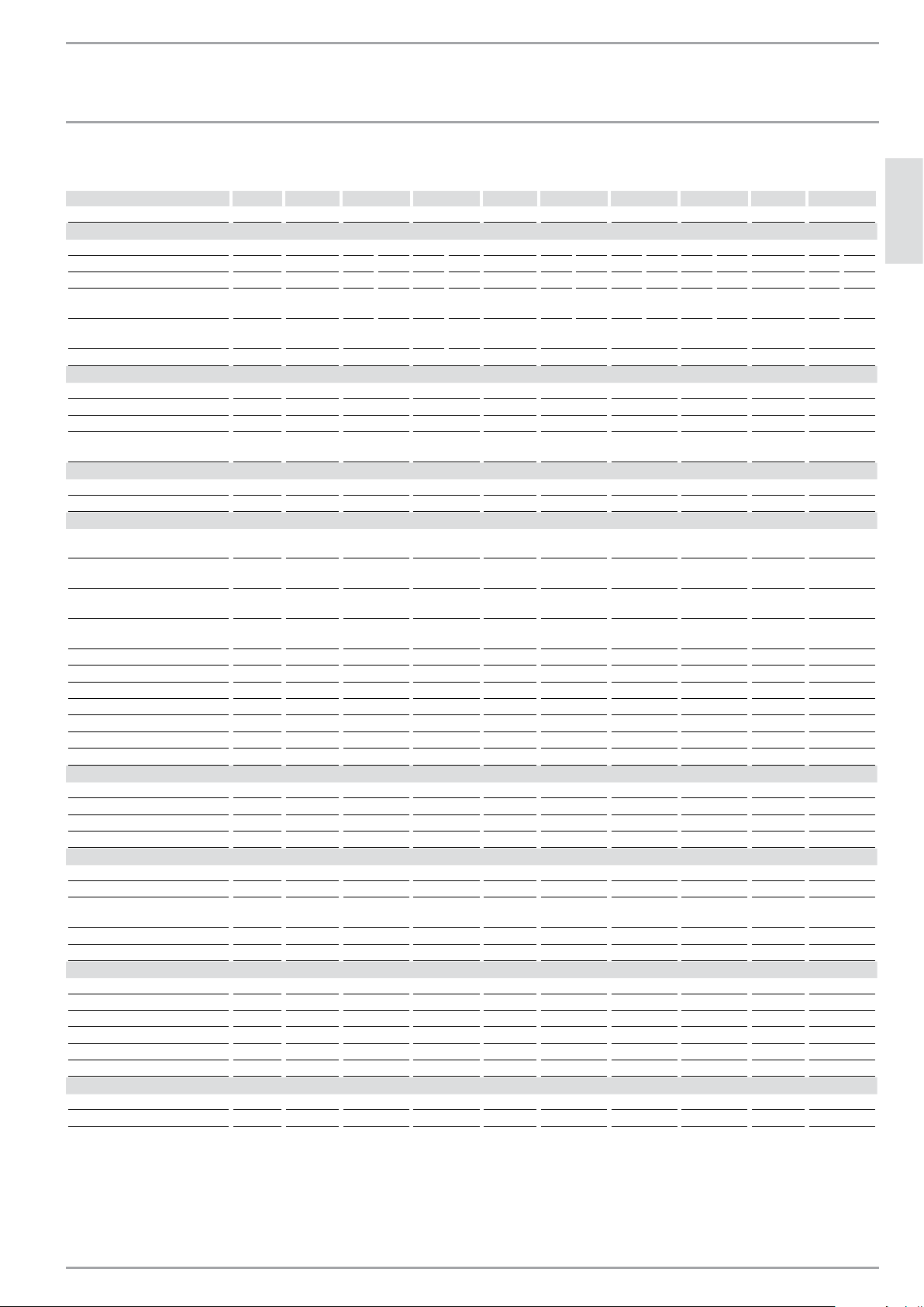
9.2 Data table
DHC 3-1 DHC 3-2 DHC 4-2 DHC 4-3 DHC 5-2 DHC 6-2 DHC 8-2 DHC 9-3 DHC 10-2
074050 074052 074053 074051 074054 074424 074055 232204 074056
Electrical details
Voltage V 120 208 240 208 240 277 208 240 208 240 208 240 277 208 240
Wattage kW 3.0 2.5 3.5 2.9 3.8 4.5 3.6 4.8 4.5 6.0 5.4 7.2 9 7.2 9.6
Ampere A 25 12 14 14 16 17 18 20 22 25 26 30 32.5 35 40
Min. recommended circuit
breaker size
1
A 25 15 15 15 20 20 20 20 25 25 30 30 35 35 40
Min. recommended wire size
(copper)
2
AWG 10 14 14 12 12 12 10 10 8 8
Power connection 1/N/GRD 2/GRD 2/GRD 2/GRD 2/GRD 2/GRD 2/GRD 2/GRD 2/GRD
Connections
Water connection
3
1/2“ NPT 1/2“ NPT 1/2“ NPT 1/2“ NPT 1/2“ NPT 1/2“ NPT 1/2“ NPT 1/2“ NPT 1/2“ NPT
Total alkaline earths mol/m³ 2.5 2.5 2.5 2.5 2.5 2.5 2.5 2.5 2.5
Total hardness (H
2
O) Degree d 14 14 14 14 14 14 14 14 14
Hardness range 2 (average
hardness)
2 (average
hardness)
2 (average
hardness)
2 (average
hardness)
2 (average
hardness)
2 (average
hardness)
2 (average
hardness)
2 (average
hardness)
2 (average
hardness)
Hydraulic data
Rated capacity l 0.5 0.5 0.5 0.5 0.5 0.5 0.5 0.5 0.5
Rated capacity gal 0.13 0.13 0.13 0.13 0.13 0.13 0.13 0.13 0.13
Values
Max. permissible inlet
temperature
°C 30 30 30 30 30 30 30 30 30
Max. permissible inlet
temperature
°F 86 86 86 86 86 86 86 86 86
Minimum water flow to activate
unit
l/min
1.2
1.2
1.6
1.6
1.6
1.8
2.6
3.0
3.0
Minimum water flow to activate
unit
GPM
0.32
0.32
0.43
0.43
0.43
0.48
0.69
0.8
0.8
Pressure drop at flow rate MPa 0.023 0.023 0.023 0.023 0.023 0.023 0.025 0.03 0.03
Pressure drop at flow rate PSI 2.88 2.88 2.88 2.88 2.88 2.88 3.13 3.75 3.75
Flow rate for pressure drop l/min 1.2 1.2 1.6 1.6 1.6 1.8 2.6 3.0 3.0
Flow rate for pressure drop GPM 0.32 0.32 0.43 0.43 0.43 0.48 0.69 0.8 0.8
DHW delivery l/min 1.2 1.2 1.6 1.6 1.6 1.8 2.6 3.0 3.0
DHW delivery GPM 0.32 0.32 0.43 0.43 0.43 0.48 0.69 0.8 0.8
Δϑ if presented K 36 30 34 40 43 48 30 43 34
Application limits
Max. permissible pressure MPa 1 1 1 1 1 1 1 1 1
Max. permissible pressure PSI 150 150 150 150 150 150 150 150 150
Test pressure MPa 2 2 2 2 2 2 2 2 2
Test pressure PSI 300 300 300 300 300 300 300 300 300
Versions
IP-Rating IP25 IP25 IP25 IP25 IP25 IP25 IP25 IP25 IP25
Material of the pressure vessel Copper Copper Copper Copper Copper Copper Copper Copper Copper
Heating system Tubular
heater
Tubular
heater
Tubular
heater
Tubular
heater
Tubular
heater
Tubular
heater
Tubular
heater
Tubular
heater
Tubular
heater
Cover and back panel Plastic Plastic Plastic Plastic Plastic Plastic Plastic Plastic Plastic
Color white white white white white white white white white
Dimensions
Height mm 360 360 360 360 360 360 360 360 360
Height in 14.17 14.17 14.17 14.17 14.17 14.17 14.17 14.17 14.17
Width mm 200 200 200 200 200 200 200 200 200
Width in 7.88 7.88 7.88 7.88 7.88 7.88 7.88 7.88 7.88
Depth mm 100 100 100 100 100 100 100 100 100
Depth in 4.33 4.33 4.33 4.33 4.33 4.33 4.33 4.33 4.33
Weights
Weight kg 2.1 2.1 2.1 2.1 2.1 2.4 2.4 2.4 2.4
Weight lb 4.6 4.6 4.6 4.6 4.6 4.6 4.6 4.6 4.6
DHC 3-1, 3-2, 4-2 ship with a 0.5 gpm (1.9 l/min) pressure compensating flow reducer/aerator that must be installed.
1
This is our recommendation for overcurrent protection sized at 100% of load. (dp for 240/208/277 v & sp for 120 v models). Check local codes for compliance if
necessary. Tankless water heater are considered a non-continuous load.
2
Copper must be used. Conductors should be sized to maintain a voltage drop of less than 3% under load
3
For use with cold water supply only
Loading ...
Loading ...
Loading ...