
Change for life
Thank you for choosing our product.
Please read this Owner’s Manual carefully before operation and
retain it for future reference.
If you have lost the Owner's Manual, go to www.greecomfort.com
for the electronic version or email info@twclimate.com
Installation & Owner's Manual
Original Instructions
Split Air Conditioner
Livo+
LIVS36HP230V1C
LIVS36HP230V1C

Content
Operation Notices
Precautions............................................................................................................ 1
Parts name ............................................................................................................ 6
Screen Operation Guide
Operation of wireless remote controller................................................................. 7
Emergency operation .......................................................................................... 15
Maintenance
Clean and maintenance.......................................................................................15
Malfunction
Malfunction analysis ............................................................................................ 18
Installation Notice
Installation dimension diagram ............................................................................22
42............................................................................................. Tools for installation
Selection of installation location .......................................................................... 24
Requirements for electric connection .................................................................. 25
Installation
Installation of indoor unit...................................................................................... 26
Installation of outdoor unit ................................................................................... 31
43................................................................................................. Vacuum pumping
Leakage detection ............................................................................................... 34
Check after installation ........................................................................................ 35
Test and operation
53...................................................................................................... Test operation
Attachment
......................................................................... 36
Pipe expanding method ....................................................................................... 38
Wired Controller(Optional)
Configuration of connection pipe
...................................................................................39
Safety precautions for installing and relocating the unit ................................... 23
Explanation of Symbols
Exception Clauses
Indicates a hazardous situation that, if not avoided, will
Manufacturer will bear no responsibilities when personal injury or
1.Damage the product due to improper use or misuse of the product;
2.Alteration, failure to properly maintain or using the product with other equipment
without adhering to the instruction manual of manufacturer;
3.After verification, the defect of product is directly caused by corrosive gas;
4.After verification, defects are due to improperly securing product during
transporting;
5.Operating, repairing or performing maintenance to the unit without following the
instruction manual or related regulations;
6.After verification, the problem or dispute is caused by the quality specification or
performance of parts and components produced by other manufacturers;
7.The damage is caused by natural external forces [such as using in a corrosive
environment, or force majeure.
property loss is caused by the following reasons.
result in death or serious injury.
Indicates a hazardous situation that, if not avoided, could
result in death or serious injury.
Indicates a hazardous situation that, if not avoided, may
result in minor or moderate injury.
Indicates important but not hazard-related information,
used to indicate risk of property damage.
Indicates a hazard that would be assigned a signal word
WARNING or CAUTION.
DANGER
WARNING
CAUTION
N OTIC E
Precautions
WARNING
Operat ion and Ma int enance
This appliance can be used by children aged from 8
years and above and persons with reduced physical,
sensory or mental capabilities or lack of experience
and knowledge if they have been given supervision or
instruction concerning use of the appliance in a safe
way and understand the hazards involved.
Children shall not play with the appliance.
Cleaning and user maintenance shall not be made by
children without supervision.
Do not connect air conditioner to multi-purpose socket.
It may create a fire hazard.
To prevent possible electrical shock, disconnect power
supply when cleaning air conditioner.
If the supply cord is damaged, it must be replaced by
the manufacturer, or similarly technically licensed and
qualified persons in order to avoid a hazard.
To avoid electric shock, do not wash the air conditioner
with water.
Do not spray water on indoor unit. It may cause electric
shock or the unit to malfunction.
To avoid injury
after removing the filter, do not touch
fins.
To avoid deformation or fire hazard, do not use
excessive heat to dry the filter.
1
● Power cord is overheating or damaged.
● Any abnormal sound during operation.
● Circuit breaker trips frequently.
● Air conditioner gives off burning smell.
● Indoor unit is leaking.
Precautions
WARNING
If the air conditioner operates abnormally,
it may
malfunction, creating electric shock or a fire hazard.
When turning on or off the unit using the emergency
switch, press with an insulated
(not metal) object.
Do not step on or place heavy objects on the outdoor
unit top panel. It could cause damage or personal
injury.
Maintenance must be performed by qualified
professionals. Otherwise, it may cause personal injury
or damage.
Do not repair air conditioner by yourself. It may cause
electric shock or damage. Please contact a licensed
HVAC contractor whenever repair is needed.
To prevent possible personal injury or damage, keep
fingers and objects clear of air inlet or outlet.
For proper air flow, keep air outlet and inlet free of
obstructions.
Do not spill water on the remote controller
, controller
may malfunction.
When any of the following occurs, please turn off air
conditioner and disconnect power immediately and
contact a licensed HVAC technician for service.
2

Precautions
WARNING
Installation must be performed by licensed, qualified
professionals.
Follow all electric safety regulations and codes when
installing the unit.
According to the local code, use qualified power
supply circuit wiring and circuit breakers.
Install circuit breakers to protect you and your equipment.
An all-pole disconnect switch having a contact separation
of
at least 3mm in all poles should be used.
Including an
circuit breaker with suitable capacity, per
the following
table.
A typical magnetic or temperature activated breaker will
protect against short circuits and overloads.
This Air Conditioner should be properly grounded.
Incorrect grounding may cause electric shock.
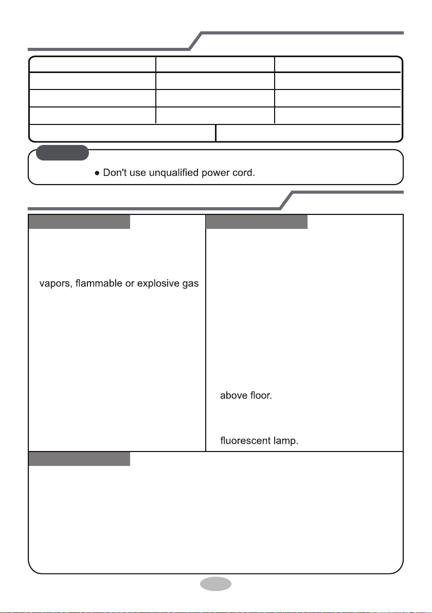
Don't use an improperly sized power cord.
Make sure the power supply matches with the
requirement of air conditioner.
Unstable power supply or
incorrect wiring can cause the
equipment to malfunction. Please install proper power
supply cables before using the air conditioner.
Follow wiring instructions to properly connect the load,
neutral and ground wires to terminals.
Be sure to disconnect the power supply before doing
any electrical or maintenance work.
Attachment
3

Precautions
WARNING
Do not turn on the power before finishing installation.
If the supply cord is damaged, it must be replaced by
the manufacturer or qualified licensed professionals in
order to avoid a hazard.
The temperature of refrigerant circuit will be high, please
keep the interconnecting wire away from the copper
tubing.
The appliance shall be installed in accordance with
national/local wiring codes/regulations.
Installation must be performed in accordance with the
requirements of NEC and CEC by authorized
personnel only.
The air conditioner is a first class electric appliance. It
must be properly grounded by a licensed professional.
Make sure the system is properly
grounded to avoid
electrical shock or fire.
The yellow-green wire in air conditioner is ground wire,
and can't be used for other purposes.
The grounding resistance should comply with national
electric safety regulations.
The appliance must be positioned so that the connection
terminals are accessible.
All wires of indoor unit and outdoor unit should be
connected by a licensed professional.
If the length of power connection wire not correct,
contact
your supplier for the correct wire length, do not splice.
4
Precautions
WARNING
All wiring terminal strips and connection boxes must be
easily accessible for installation and service.
For the air conditioner without plug, an circuit breaker
must be installed and easily accessible.
To avoid personal injury or damage,relocation of the
air conditioner should only be done by a qualified
person.
Select a location which is out of reach for children
and far away from animals or plants. If it is
unavoidable, please add a fence for safety purposes.
The indoor unit should be installed close to the wall.
Instructions for installation and use of this product are
provided by the manufacturer.
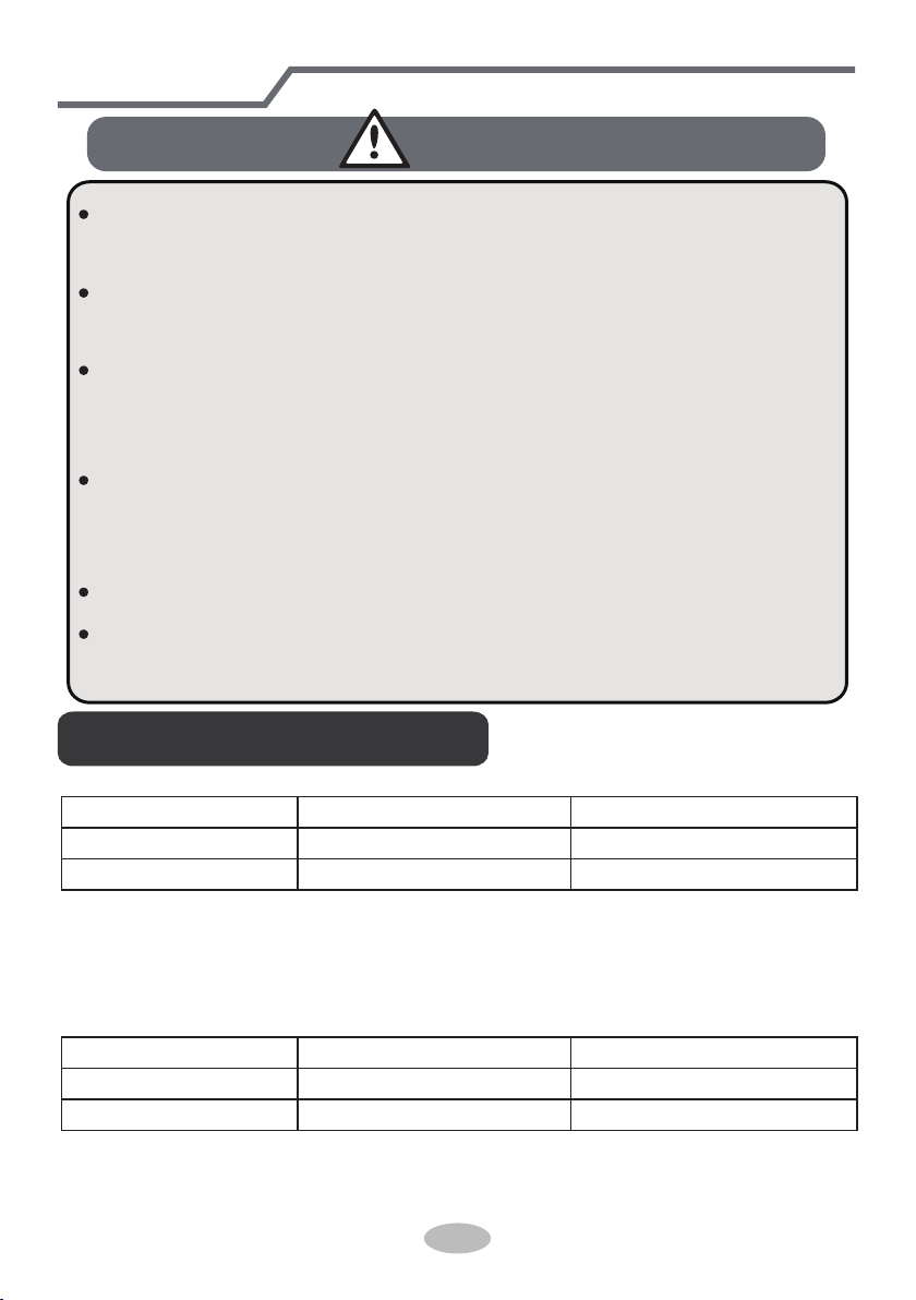
NOTICE:
Indoor side DB/WB(
℃/°F
) Outdoor side DB/WB(
℃/°F
)
Maximum cooling 27/19(80.6/66.2) 46/24(114.8/75.2)
Maximum heating 27/-(80.6/-) 24/18(75.2/64.4)
● The operating temperature range (outdoor temperature) for cooling only unit is
For some models:
For model:
LIVS36HP230V1C
-15
℃
~ 46
℃(5 ~ 114.8°F)
; for heat pump unit is -20
℃
~ 46
℃(-4 ~ 114.8°F).
NOTICE:
Indoor side DB/WB(
℃/°F
) Outdoor side DB/WB(
℃/°F
)
Maximum cooling 27/19(80.6/66.2) 46/24(114.8/75.2)
Maximum heating 27/-(80.6/-) 24/18(75.2/64.4)
● The operating temperature range (outdoor temperature) for the heat pump unit
is -20℃ ~ 46℃(-5 ~ 114.8°F).
5
Working temperature range
6
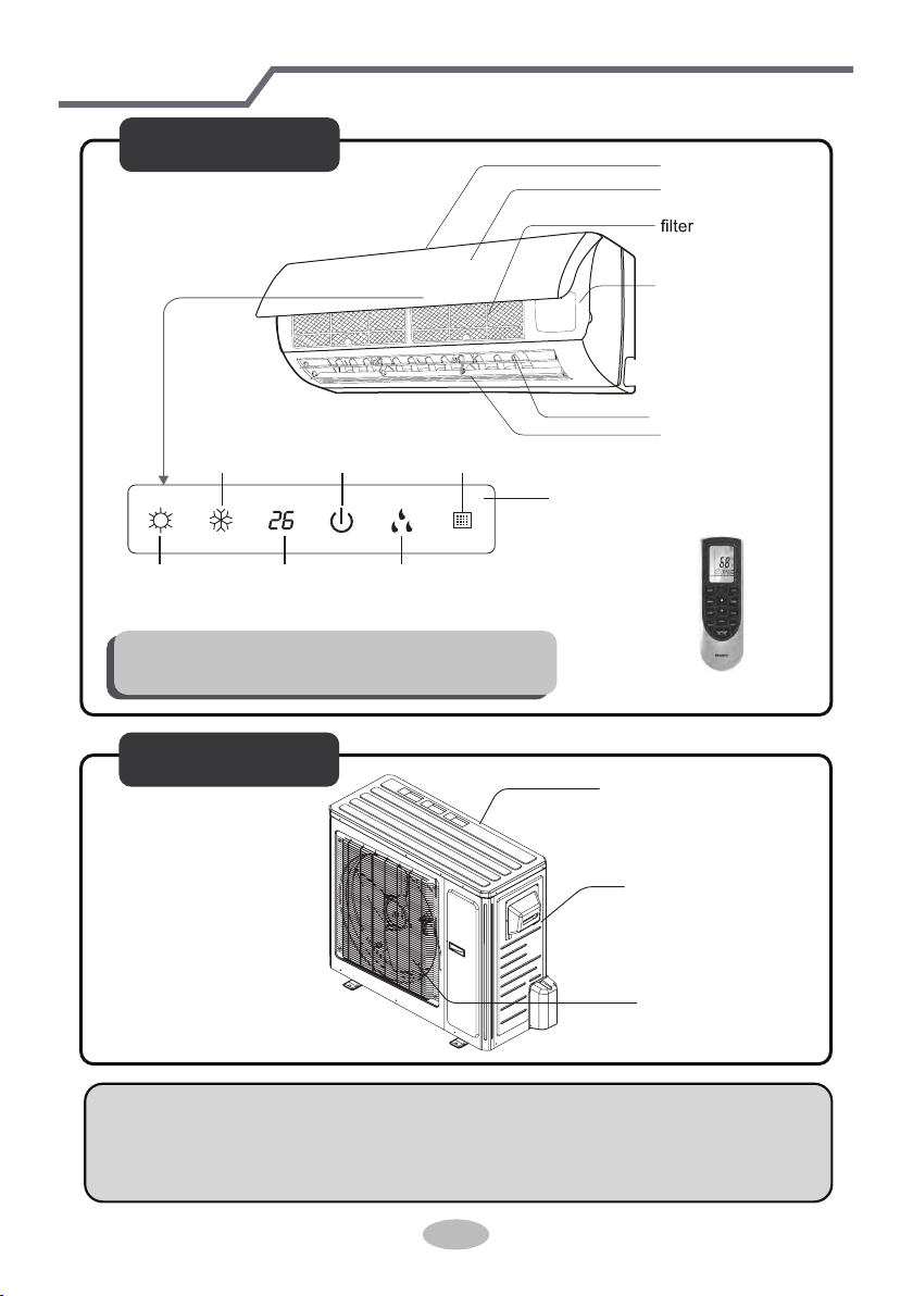
Parts name
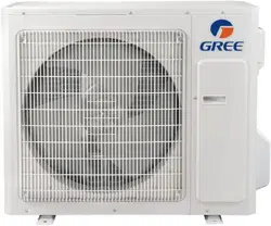
Outdoor Unit
air inlet
Connection wire
air outlet
(Display content or position may be different from above
graphics, please refer to actual products)
Indoor Unit
air inlet
panel
aux.button
horizontal louver
air outlet
heating
indicator
temp.
indicator
cooling
indicator
power
indicator
receiver
window
drying
indicator
display
NOTICE:
Actual product may be different from above graphics, please refer to actual
products.
remote control
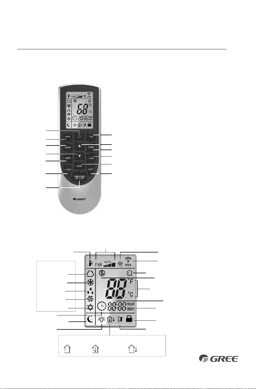
Remote Controller
INTRODUCTION FOR ICONS ON DISPLAY SCREEN
OPERATION OF WIRELESS REMOTE CONTROLLER
Part Name
1. ON/OFF Button
2. Fan Button
3. Mode Button
4. Up Button
5. Swing Button
6. Turbo Button
7. Down Button
8. Temp Button
9. Sleep Button
10. I Feel Button
11. Clock Button
12. Light Button
13. Timer On/Off Button
1
3
5
7
9
11
2
4
6
8
10
12
13
Auto Mode
Cool Mode
Dry Mode
Fan Mode
Heat Mode
Clock
Sleep Mode
I Feel Function
Light
Send Signal
Turbo Mode
Set Fan Speed
Operation Mode
Temp.Display Type
Set Temperature
Set Time
Timer On/Off
Privacy Lock
Up & Down Swing
Set Temp.
Indoor
Ambient Temp.
Outdoor
Ambient Temp.
Temp. Display Type
Freeze Guard
7
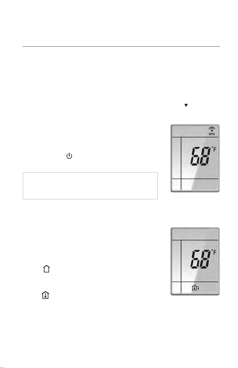
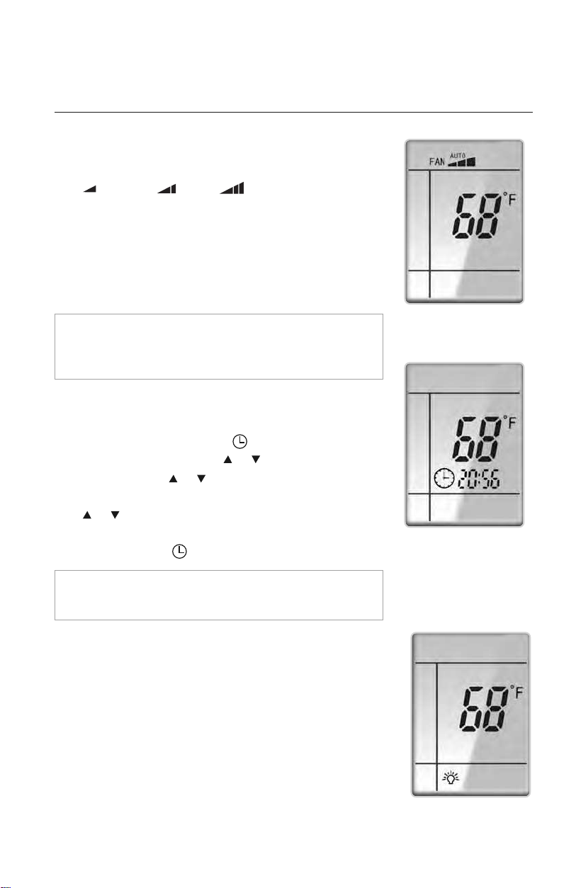
DISPLAYING SETPOINT OR INDOOR TEMPERATURE
ON FRONT PANEL:
The setpoint temperature or room temperature can be displayed on
the front panel. Only setpoint temperature is displayed on the remote
controller.
When the “TEMP” button is pushed once, the temperature
indicator is displayed. This indicates that the setpoint temperature
is displayed on the front panel.
When the “TEMP” button is pushed a second time, the display will
show an icon with a thermometer inside a house. This indicates
that the room temperature is displayed on the front panel.
The room temperature will be displayed for only 5 seconds before
reverting back to displaying room setpoint.
OPERATION OF WIRELESS REMOTE CONTROLLER
REMOTE CONTROLLER OPERATIONS
The wireless remote controller is sleek, versatile and allows you to change room temperatures
and functions on your Vireo system from the palm of your hand. The large LCD display and
buttons make it easy-to-understand and easy-to-use.
The remote controller is set from factory to display temperatures in °F. If °C is desired, turn the
remote controller OFF with the ON/OFF button and then press “MODE“ and “ ” buttons
on the remote simultaneously for 5 seconds.
ON/OFF BUTTON
When the system is in OFF mode, the remote controller will display
the time and last room setpoint. When you press the ON/OFF
button, this indicator will be displayed and the unit will start in
the last operating mode and room setpoint.
NOTE: If the ON/OFF button is pressed too soon after a
stop, the compressor will not start for 1 to 5 min. due to the
inherent protection against frequent compressor cycling.
ON Mode Display
Room Temperature Display
8
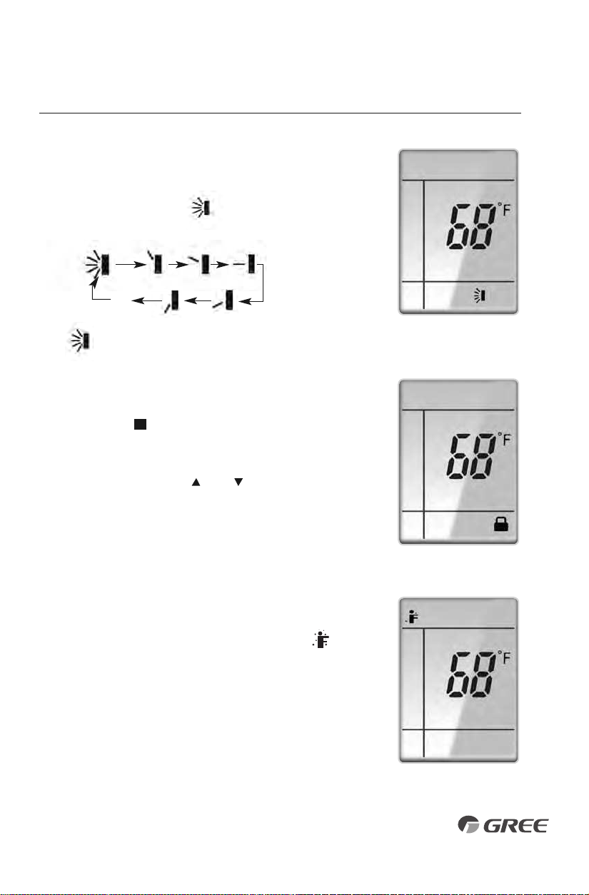
PRIVACY LOCK
The Privacy Lock prevents unauthorized access to the unit controls
and prevents tampering with system settings. The remote controller
can be locked by pushing the""and " " buttons simultaneously
for 5 seconds. The Privacy Lock icon will be displayed on the remote
controller. Repeat the process to unlock the remote controller.
U
Privacy Lock Display
OPERATION OF WIRELESS REMOTE CONTROLLER
VERTICAL SWING LOUVERS
•
Press the Vertical Swing Louver button to select five different
vertical (up & down) air discharge directions including Continuous
Sweep. The Swing Louver icon will be displayed. Press this
button to set swing angle, which changes in direction as below:
Indicates louver swings up and down in
the five directions, as shown.
OFF
1023
4
5
Swing Louver Display
I Feel Mode
I FEEL MODE
Press this button to use the I FEEL function, and the ( ) icon
will be displayed. The unit will sense room temperature at the
remote controller instead of at the indoor unit during cooling
mode. It then adjusts airflow and temperature accordingly for
the ultimate in personal comfort control and energy savings.
Press the button again to exit this function. For best performance,
keep remote controller away from heat or cold temperature
sources while using this function.
9
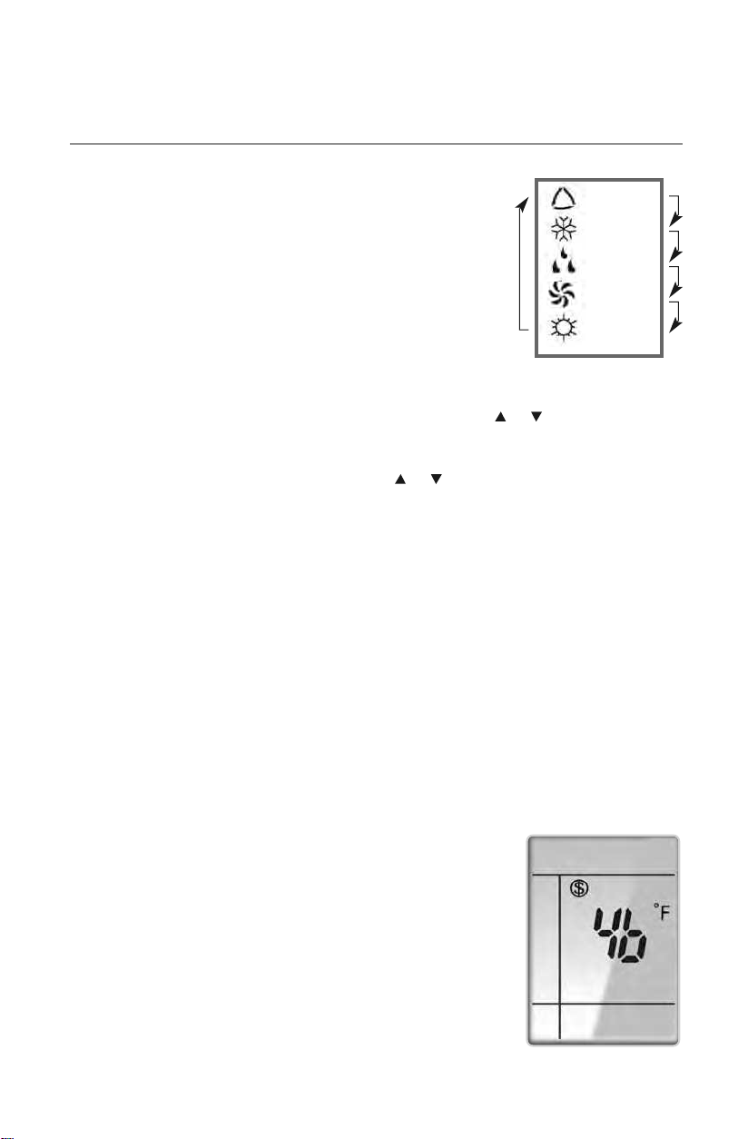
MODE BUTTON
Use the “MODE” button to select one of the available modes.
The selected mode will be displayed on the remote controller and
the appropriate light will illuminate on the front display panel.
AUTO – Unit will automatically select heating or cooling to
maintain room temperature between 68°F and 77°F.
The remote controller will display the Auto Mode icon with
no setpoint.
COOL – To cool to selected setpoint and remove moisture. Press or to adjust
set temperature. System varies compressor speed to maintain desired temperature.
HEAT – To heat to selected room setpoint. Press or to adjust set temperature.
System varies compressor speed to maintain desired room temperature.
FAN ONLY – To circulate air without heating or cooling. Use Fan Speed button to select
speed from low to high.
DRY – Select DRY MODE to increase moisture removal during warm humid conditions.
In this mode, fan speed cannot be adjusted.
1. If the Room Temperature is more than 4°F above the set temperature, the
system will be operating in cooling mode with low fan speed.
2. If the Room Temperature is between 4°F higher than, and 4°F less than, the set
temperature, the system will cycle 6 minutes ON and 4 minutes OFF in cooling
mode. The indoor fan will be at low speed.
3. If the Room Temperature is more than 4°F below the set temperature, the system
will be OFF and the indoor fan will be at low speed.
: AUTO
: COOL
: DRY
:
FAN ONLY
: HEAT
Icons Displayed
OPERATION OF WIRELESS REMOTE CONTROLLER
FREEZE GUARD
In Heat mode, press"TEMP"and "CLOCK" buttons simultaneously
to start up 46°F heating function. When this function is started up,
"($)" and "46°F" will be displayed on the remote controller, and
the unit will maintain room temperature above 46°F. Press"TEMP"
and "CLOCK" buttons simultaneously again to cancel Freeze
Guard protection.
Freeze Guard Display
10
OPERATION OF WIRELESS REMOTE CONTROLLER
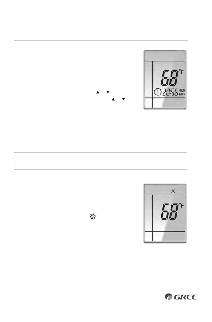
TIMER SETTING
Timer-ON / Timer-OFF BUTTON
To set when you want the unit to turn On at the end of a selected
time period, use the button labeled “Timer-ON /Timer-OFF”on the
remote controller. Press this button to make the clock icon disappear,
replaced with the word “ON” (blinking). Press or buttons to
adjust timer setting 1 minute
at a time. Press and hold
or
button to set timer more quickly. Press“Timer-ON /Timer-OFF”
button again to confirm setting, and the word “ON” will stop
blinking. To cancel, press“Timer-ON /Timer-OFF” button again.
To set when you want the unit to turn Off at the end of a selected time period, use the
same button. Press this button to make the clock icon disappear, replaced with the word
“OFF” (blinking). Adjust settings the same as with
“Timer-ON /Timer-OFF”
settings.
NOTE: Under Timer On and Off status, you can set“Timer-ON /Timer-OFF”simultaneously.
Before setting timer, be sure to set clock to correct time.
TURBO MODE
The desired room setpoint can be achieved faster in TURBO
mode. After selecting the“HEAT”or“COOL” mode button,
push the“TURBO”button. The TURBO icon will be
displayed on the remote controller and the unit will run at an
ultra-high speed. To deactivate the feature, push the“TURBO”
button again. The unit will return to normal operation.
Timer Setting ON/OFF
Turbo Mode Display
11
FAN BUTTON
Press the FAN button to adjust the indoor fan speed:
Low ( ), Medium ( ), High ( ), Turbo and Auto.
NOTE: Turbo function is not available in Dry and Auto Modes.
The Livo unit will select proper fan speed automatically
according to ambient temperature.
OPERATION OF WIRELESS REMOTE CONTROLLER
CLOCK SETTING
Press this button to set clock time.“ ” icon on remote controller
will blink. Within 5 seconds, press or button to set clock time.
With each pressing of or buttons, clock time will increase
or decrease 1 minute. To quickly adjust time setting, press and
hold or button for 2 seconds. Release button when you
have reached the desired time setting. Press “CLOCK” button to
confirm the time, and “ ” icon will stop blinking.
NOTE:
Clock time adopts 24-hour mode. A 12-hour time
format is not available.
• Turbo function is not available in Dry and Auto mode.
• The fan operates at low speed in Dry and Auto modes, and the
speed cannot be adjusted.
• When Auto is selected, the unit will select the proper fan speed
automatically, according to the ambient temperature.
Fan Display
Clock Setting Display
LIGHT BUTTON
Press this button to turn off display light on indoor unit.
Press again to turn it back on.
Light Display
12
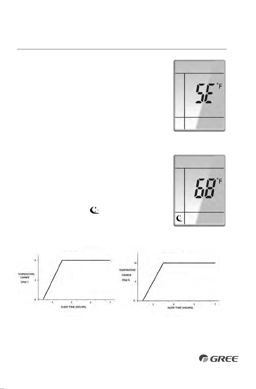
Cooling Mode
Heating Mode
ENERGY-SAVING
In Cool mode, press"TEMP" and "CLOCK" buttons simultaneously
to start the energy-saving function."SE" will be shown on remote
controller, and the unit will adjust the set temperature automatically
to reach to the best energy-saving effect. Press"TEMP"and "CLOCK"
buttons simultaneously again to cancel energy-saving mode.
Energy Saving Display
OPERATION OF WIRELESS REMOTE CONTROLLER
SLEEP MODE
The Livo system will automatically adjust room temperature
during your sleep time. This slight change in temperature will
not affect your comfort level due to the natural effects that
sleeping has on the body, but it will save on energy consumption
and will lower your electric bill. Press the SLEEP button to select
Sleep Mode
or Cancel. The SLEEP icon will appear.
In Sleep Mode the unit will slowly relax the room set temperature
by up to 4° F until Sleep Mode is cancelled.
Sleep Mode Display
13
OPERATION OF WIRELESS REMOTE CONTROLLER
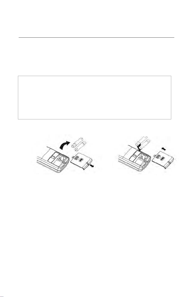
CHANGING BATTERIES AND ADDITIONAL NOTES
To change batteries, slide cover off battery compartment on back of remote controller. Remove
and safely discard old batteries. Insert two new AAA 1.5V dry batteries, using correct polarity.
Reattach back cover.
NOTE:
• If the remote controller will not be used for a long time, remove batteries to prevent
leakage damage.
• Be sure to aim the remote controller at the receiver of the main unit when operating.
• When remote emits a signal, icon will flicker; a tone will be heard when unit receives
that signal.
Remove
old batteries
Install
new batteries
CHANGING BATTERIES
14
15
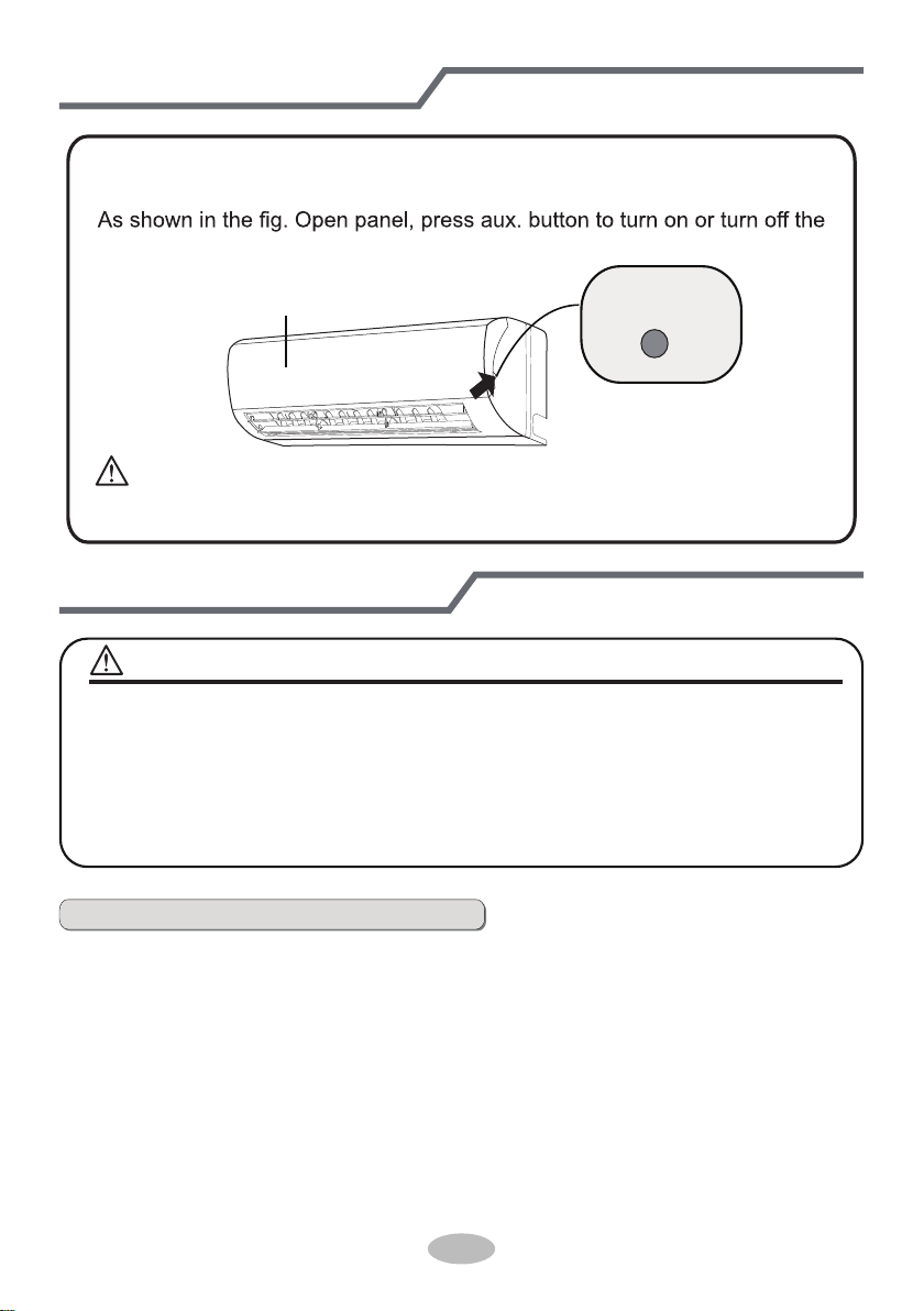
Emergency operation
If remote controller is lost or damaged, please use auxiliary button to turn
on or turn off the air conditioner. The operation in details are as below:
air conditioner. When the air conditioner is turned on, it will operate under
auto mode.
aux. button
panel
Clean and maintenance
■ Turn off the air conditioner and disconnect the power before cleaning the air
conditioner to avoid electric shock.
■ Do not wash the air conditioner with water to avoid electric shock.
■ Do not use volatile liquid to clean the air conditioner.
Clean surface of indoor unit
When the surface of indoor unit is dirty, it is recommended to use a soft dry cloth
or wet cloth to wipe it.
● Do not remove the panel when cleaning it.
WARNING
NOTICE:
WARNING:
Use insulated object to press the auto button
16
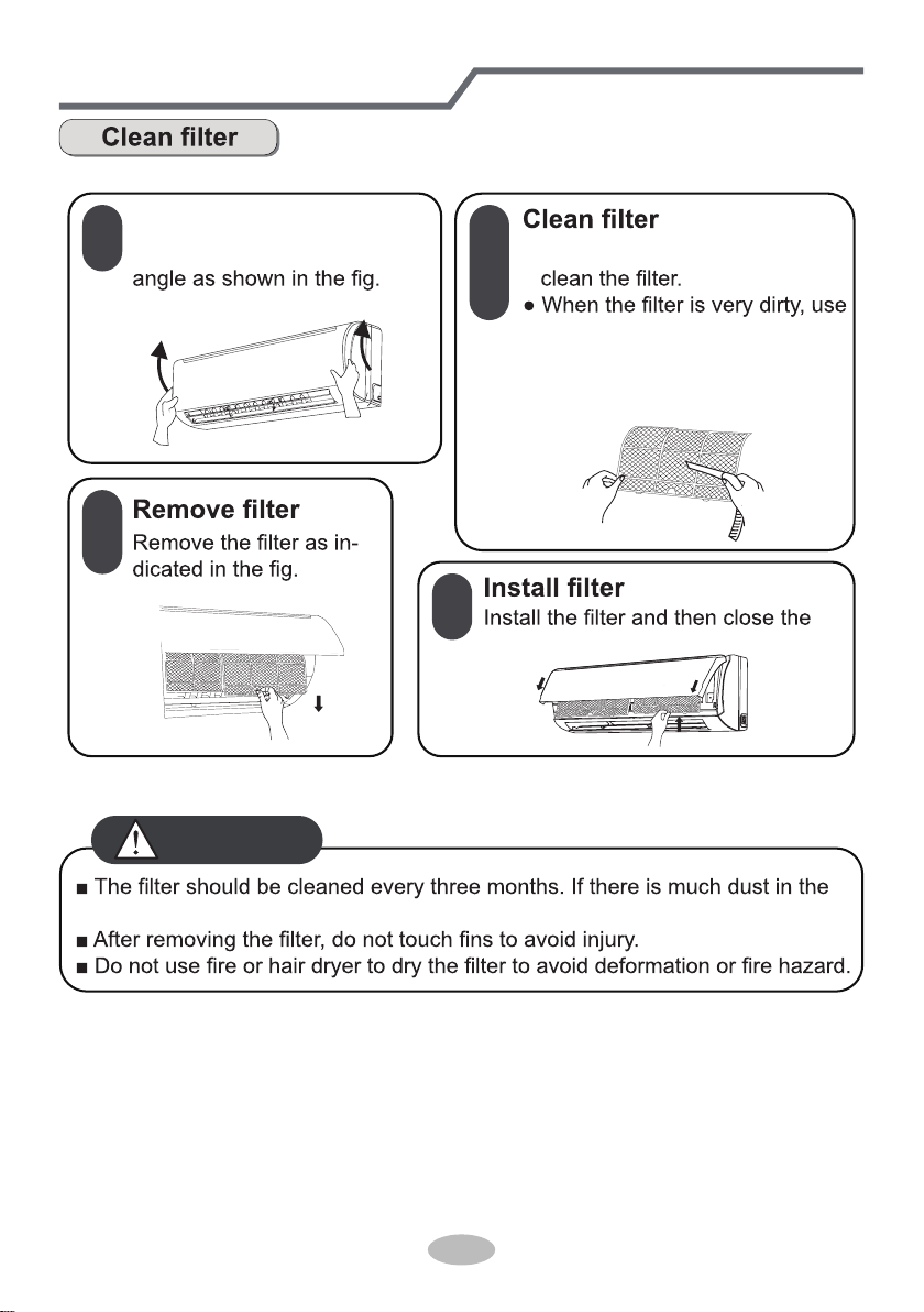
Clean and maintenance
1
2
3
4
Open panel
Pull out the panel to a certain ● Use dust catcher or water to
the water (below 45
℃
(113°F))
to clean it, and then put it in a
shady and cool place to dry.
panel cover tightly.
operation environment, clean frequency can be increased.
WARNING
17
Clean and maintenance
1. Check whether air inlets and air outlets are blocked.
2. Check whether circuit break, plug and socket are in good condition.
4. Check whether mounting bracket for outdoor unit is damaged or corroded.
If yes, please contact dealer.
5. Check whether drainage pipe is damaged.
1. Disconnect power supply.
3. Check whether mounting bracket for outdoor unit is damaged or corroded.
If yes, please contact dealer.
Notice for recovery
1. Many packing materials are recyclable materials.
Please dispose them in appropriate recycling unit.
2. If you want to dispose the air conditioner, please contact local dealer or
consultant service center for the correct disposal method.
NOTICE: Checking before use-season
NOTICE: Checking after use-season
18
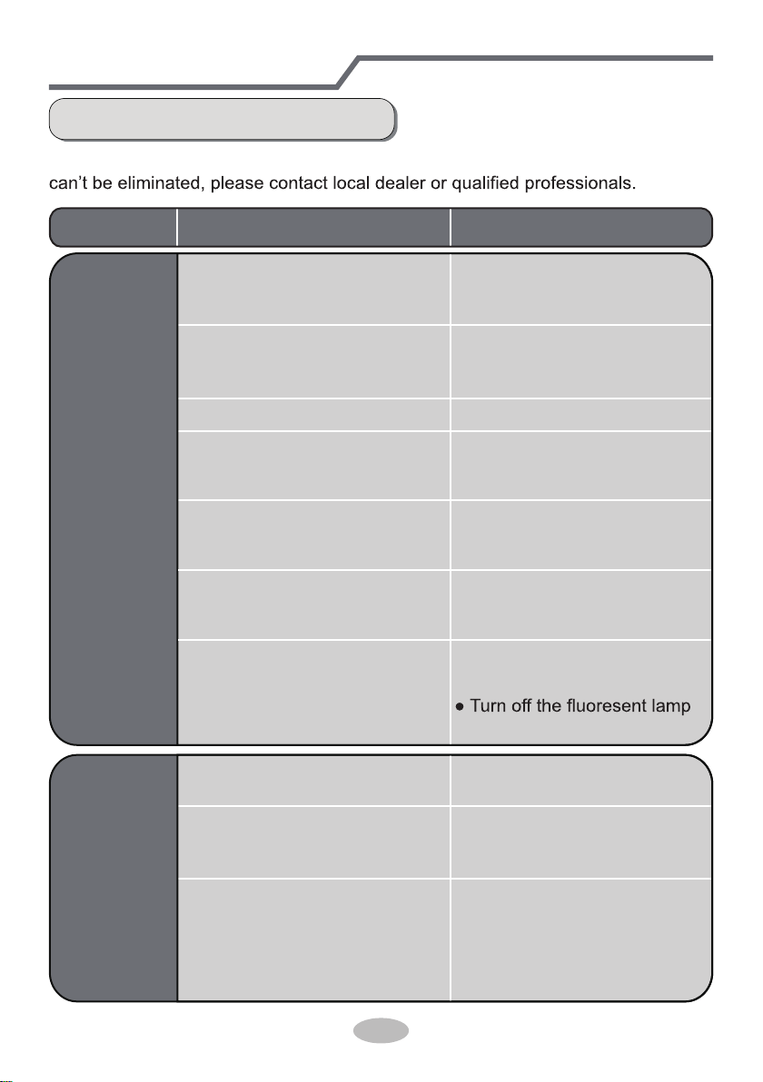
Malfunction analysis
General trouble shooting
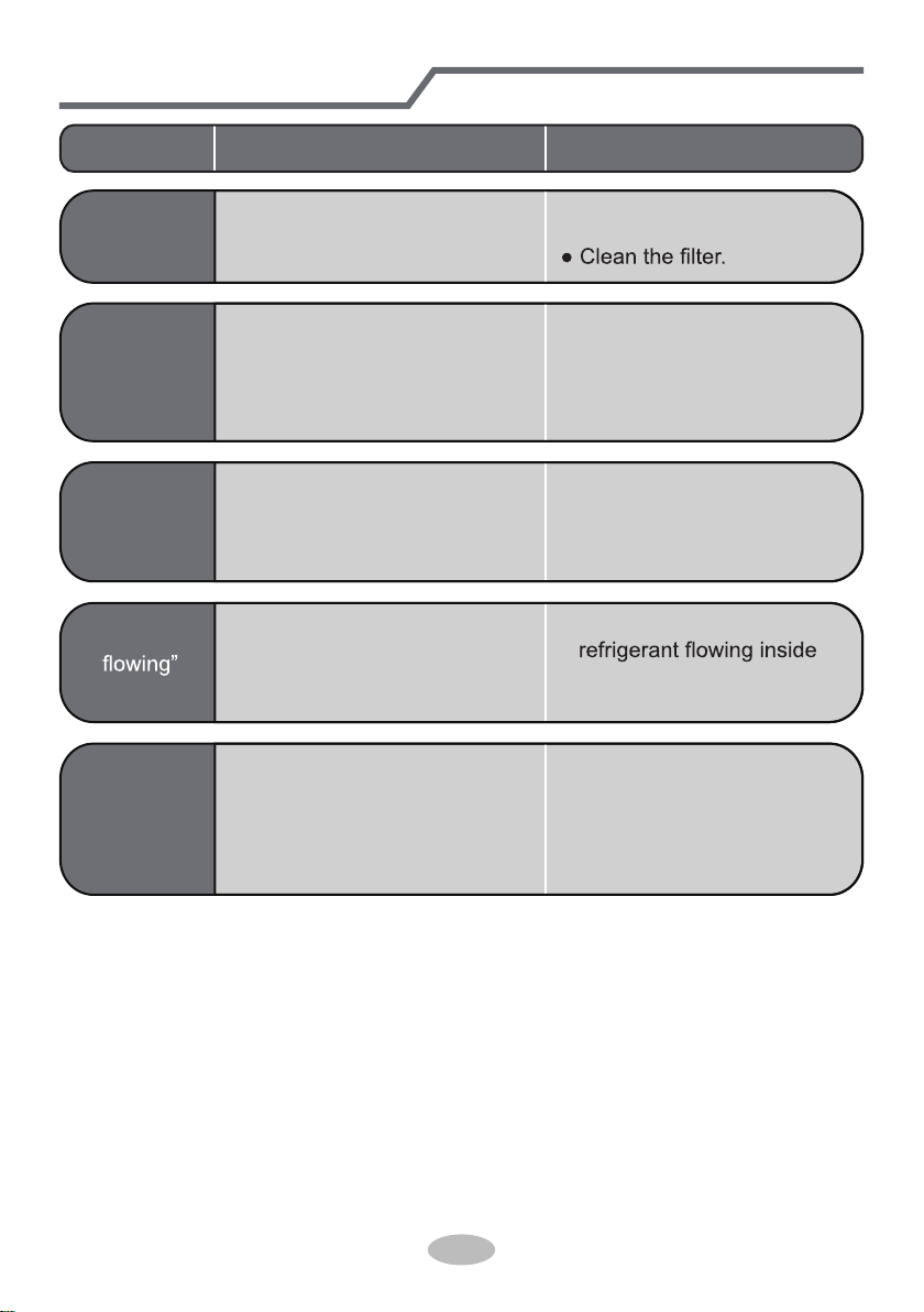
Please check below items before asking for maintenance. If the malfunction still
Problem Check items Solution
Indoor unit
can’t receive
remote
controller’s
signal or
remote
controller
has no
action.
● Whether it's interfered severely
(such as static electricity, stable
voltage)?
● Whether remote controller is
within the signal receiving
range?
● Whether there are obstacles?
● Whether remote controller is
pointing at the receiving
window?
● Is sensitivity of remote contro-
ller low; fuzzy display and no
display?
● No display when operating
remote controller?
● Fluorescent lamp in room?
● Pull out the plug. Reinsert
the plug after about 3min, and
then turn on the unit again.
● Signal receiving range is 8m.
● Remove obstacles.
●
Select proper angle and point
the remote controller at the re-
ceiving window on indoor unit.
● Check the batteries. If the
power of batteries is too low,
please replace them.
● Take the remote controller
close to indoor unit.
and then try it again.
● Check whether remote cont-
roller appears to be damaged.
If yes, replace it.
No air
emitted
from
indoor
unit
● Air inlet or air outlet of indoor
unit is blocked?
● Eliminate obstacles.
● Under heating mode, indoor
temperature is reached to set
temperature?
● After reaching to set temper-
ature, indoor unit will stop bl-
owing out air.
● Heating mode is turned on just
now?
● In order to prevent blowing
out cold air, indoor unit will be
started after delaying for sev-
eral minutes, which is a nor-
mal phenomenon.
19
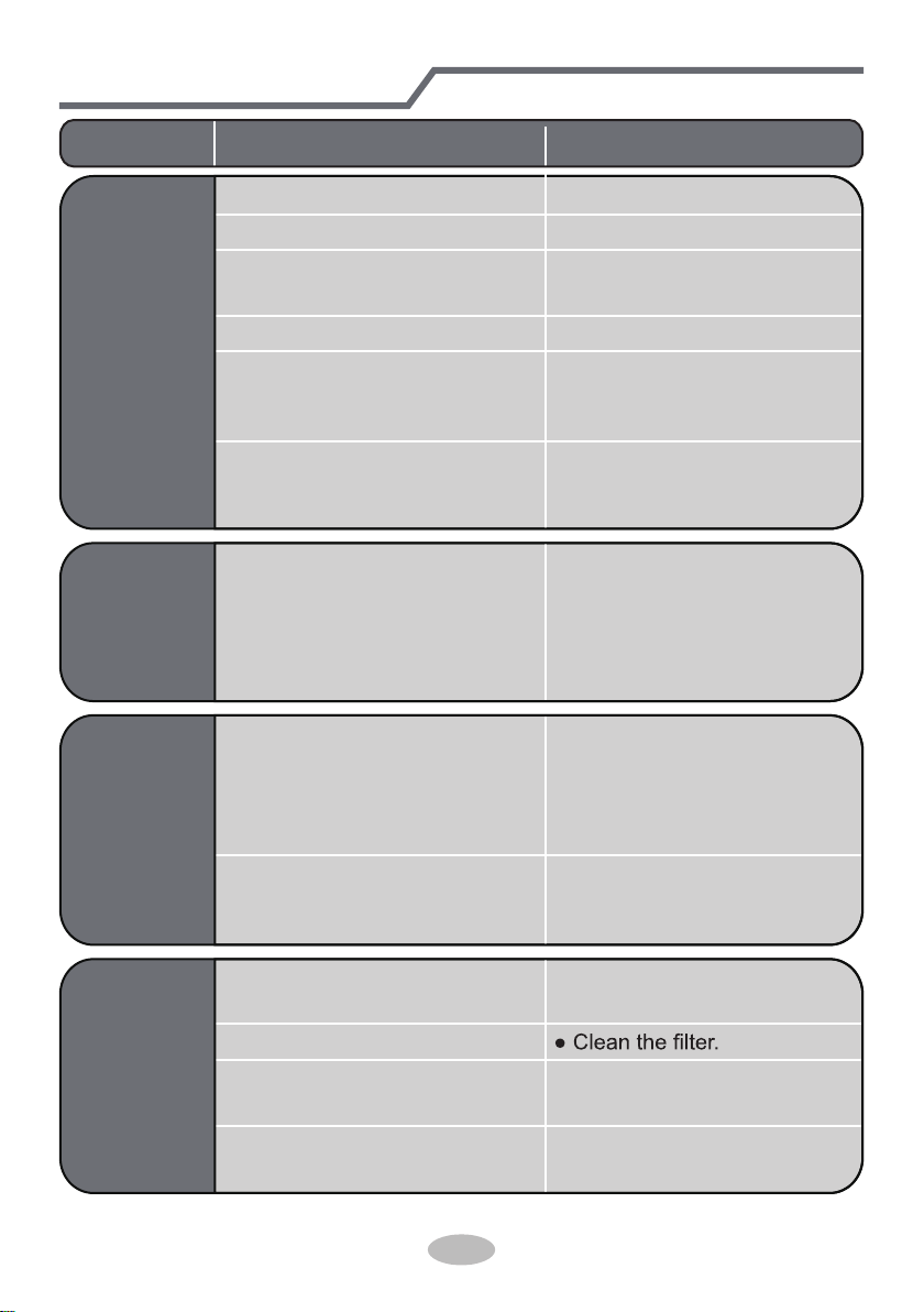
Malfunction analysis
● Power failure?
● Is plug loose?
● Circuit break trips off or
fuse is burnt out?
● Wiring has malfunction?
● Unit has restarted immediately
after stopping operation?
● Whether the function setting
for remote controller is
correct?
● Reset the function.
● Wait for 3min, and then turn
on the unit again.
● Ask professional to replace it.
● Ask professional to replace
circuit break or fuse.
● Reinsert the plug.
● Wait until power recovery.
Air condit-
ioner can’t
operate
Mist is em-
itted from
indoor unit’s
air outlet
● Indoor temperature and hum-
idity is high?
● Because indoor air is cooled
rapidly. After a while, indoor
temperature and humidity will
be decrease and mist will
disappear.
Problem Check items Solution
Set temper-
ature can’t
be adjusted
● Unit is operating under auto
mode?
● Temperature can’t be adju-
sted under auto mode.
Please switch the operation
mode if you need to adjust
temperature.
● Your required temperature
exceeds the set temperature
range?
● Set temperature range:
16
℃
~30
℃
.
Cooling
(heating)
effect is
not good.
● Voltage is too low?
● Wait until the voltage
resumes normal.
● Filter is dirty?
● Set temperature is in proper
range?
● Adjust temperature to proper
range.
● Door and window are open? ● Close door and window.
20
Problem Check items Solution
Odors are
emitted
● Whether there’s odour source,
such as furniture and cigarette,
etc.
● Eliminate the odour source.
Air conditio-
ner operates
abnormally
● Whether there’s interference,
such as thunder, wireless
devices, etc.
● Disconnect power, put back
power, and then turn on the
unit again.
Outdoor
unit has
vapor
● Heating mode is turned on?
● During defrosting under he-
ating mode, it may generate
vapor, which is a normal
phenomenon.
“Water
noise
● Air conditioner is turned on or
turned off just now?
● The noise is the sound of
the unit, which is a normal
phenomenon.
Cracking
noise
● Air conditioner is turned on or
turned off just now?
● This is the sound of friction
caused by expansion and/or
contraction of panel or other
parts due to the change of
temperature.
Malfunction analysis
21
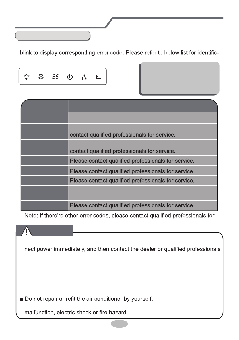
Malfunction analysis
Error Code
● When air conditioner status is abnormal, temperature indicator on indoor unit will
ation of error code.
Indoor
display
Error code
Above indicator diagram is only
for reference. Please refer to
actual product for the actual
indicator and position.
■ When these problems occur, please turn off air conditioner and discon-
for service.
● Power cord is overheating or damaged.
● There’s abnormal sound during operation.
● Circuit break trips off frequently.
● Air conditioner gives off burning smell.
● Indoor unit is leaking.
■ If the air conditioner operates under abnormal conditions, it may cause
service.
Error code
E5
H6
C5
F1
F2
E6
Troubleshooting
t
It can be eliminated af er restarting the unit. If not, please
It can be eliminated after restarting the unit. If not, please
F0
Means defrosting status. It’s the normal phenomenon.
H1( )
Heating indicator
ON 10s OFF 0.5s
It can be eliminated after restarting the unit. If not, please
contact qualified professionals for service.
WARNING
22
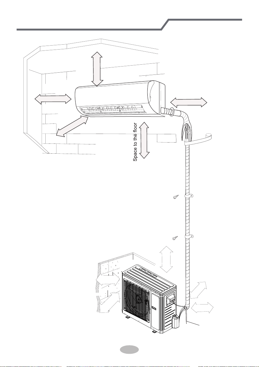
Installation dimension diagram
At least 250cm
At least 15cm
At least 300cm
Space to the ceiling
Space to the obstruction
At least 15cm
At least 15cm
Space to the wall
Space to the wall
Space to the wall
Above
Above
50cm
Air inlet side
00
Space to the obstruction
Air outlet side
0cm20
Above
Above
30cm
30cm
Space to the wall
Drainage pipe
Above
50cm
23
To ensure safety, please be mindful of the following precautions.
Warning
When installing or relocating the unit, be sure to keep the refrigerant
circuit free from air or substances other than the specified refrigerant.
Any presence of air or other foreign substance in the refrigerant circuit will cause
system pressure rise or compressor rupture, resulting in injury.
When installing or moving this unit, do not charge the refrigerant which
is not comply with that on the nameplate or unqualified refrigerant.
Otherwise, it may cause abnormal operation, wrong action, mechanical
malfunction or even series safety accident.
When refrigerant needs to be recovered during relocating or repairing the
unit, be sure that the unit is running in cooling mode.Then, fully close the
valve at high pressure side (liquid valve).About 30-40 seconds later, fully
close the valve at low pressure side (gas valve), immediately stop the unit
and disconnect power. Please note that the time for refrigerant recovery
should not exceed 1 minute.
If refrigerant recovery takes too much time, air may be sucked in and cause
pressure rise or compressor rupture, resulting in injury.
During refrigerant recovery, make sure that liquid valve and gas valve are
fully closed and power is disconnected before detaching the connection pipe.
If compressor starts running when stop valve is open and connection pipe is not
yet connected, air will be sucked in and cause pressure rise or compressor
rupture, resulting in injury.
When installing the unit, make sure that connection pipe is securely
connected before the compressor starts running.
If compressor starts running when stop valve is open and connection pipe is not
yet connected, air will be sucked in and cause pressure rise or compressor
rupture, resulting in injury.
Prohibit installing the unit at the place where there may be leaked corrosive
gas or flammable gas.
If there leaked gas around the unit, it may cause explosion and other accidents.
Do not use extension cords for electrical connections. If the electric wire
is not long enough, please contact a local service center authorized
and ask for a proper electric wire.
Poor connections may lead to electric shock or fire.
Use the specified types of wires for electrical connections between the
indoor and outdoor units. Firmly clamp the wires so that their terminals
receive no external stresses.
Electric wires with insufficient capacity, wrong wire connections and insecure
wire terminals may cause electric shock or fire.
Safety precautions for installing and relocating the unit
● Please contact the local agent for installation.
Indoor unit
1. There should be no obstruction near air
inlet and air outlet.
2. Select a location where the condensat-
ion water can be dispersed easily and
won't affect other people.
Select a location which is convenient to
connect the outdoor unit and near the
power socket.
Select a location which is out of reach
for children.
The location should be able to withstand
the weight of indoor unit and won't incr-
ease noise and vibration.
1.The place with strong heat sources,
or volatile objects spread in the air.
,
The place with high-frequency
devices (such as welding machine,
medical equipment).
The place near coast area.
The place with oil or fumes in the air.
3.
2.
4.
5.
5.The place with sulfureted gas.
6.
7.
6.
The appliance must be installed 2.5m
8.
7. Don't install the indoor unit right above
the electric appliance.
8. Please try your best to keep way from
Outdoor unit
1.
2.
3.
4. Make sure that the installation follows the requirement of installation
dimension diagram.
Select a location which is out of reach for children and far away from animals
or plants. If it is unavoidable, please add the fence for safety purpose.
5.
24
Tools for installation
Note:
Selection of installation location
Basic requirement
Installing the unit in the following pla-
ces maycause malfunction. If it is un-
avoidable, please consult the local dealer:
3.
4.
Select a location where the noise and outflow air emitted by the outdoor unit
The location should be well ventilated and dry, in which the outdoor unit
won't be exposed directly to sunlight or strong wind.
The location should be able to withstand the weight of outdoor unit.
1 Level meter
4 Drill head
7 Open-end wrench
10 Vacuum pump
13 Inner hexagon spanner
2 Screw driver
5 Pipe expander
8 Pipe cutter
11 Pressure meter
3 Impact drill
6 Torque wrench
9 Leakage detector
12 Universal meter
14 Measuring tape
Other places with special circumstances.
The appliance shall not be installed
in the laundry.
It’s not allowed to be installed on
the
unstable or motive base structure
(such
as truck) or in the corrosive environ-
ment (such as chemical factory).
will not affect neighborhood.
25
Requirements for electric connection
Safety precaution
Grounding requirement
1. Must follow the electric safety regulations when installing the unit.
circuit break.
3. Make sure the power supply matches with the requirement of air conditioner.
Unstable power supply or incorrect wiring or malfunction. Please install proper
power supply cables before using the air conditioner.
4. Properly connect the live wire, neutral wire and grounding wire of power socket.
5. Be sure to cut off the power supply before proceeding any work related to
electricity and safety.
7. If the supply cord is damaged, it must be replaced by the manufacturer, its
8. The temperature of refrigerant circuit will be high, please keep the interconnec-
tion cable away from the copper tube.
9. The appliance shall be installed in accordance with national wiring regulations.
10.Installation must be performed in accordance with the requirement of NEC
and CEC by authorized personnel only
grounding with specialized grounding device by a professional. Please make
sure it is always grounded effectively, otherwise it may cause electric shock.
2. The yellow-green wire in air conditioner is grounding wire, which can't be used
for other purposes.
3. The grounding resistance should comply with national electric safety regulations.
4. The appliance must be positioned so that the plug is accessible.
5. An all-pole disconnection switch having a contact separation of at least 3mm in
26
Installation of indoor unit
Step one: choosing installation location
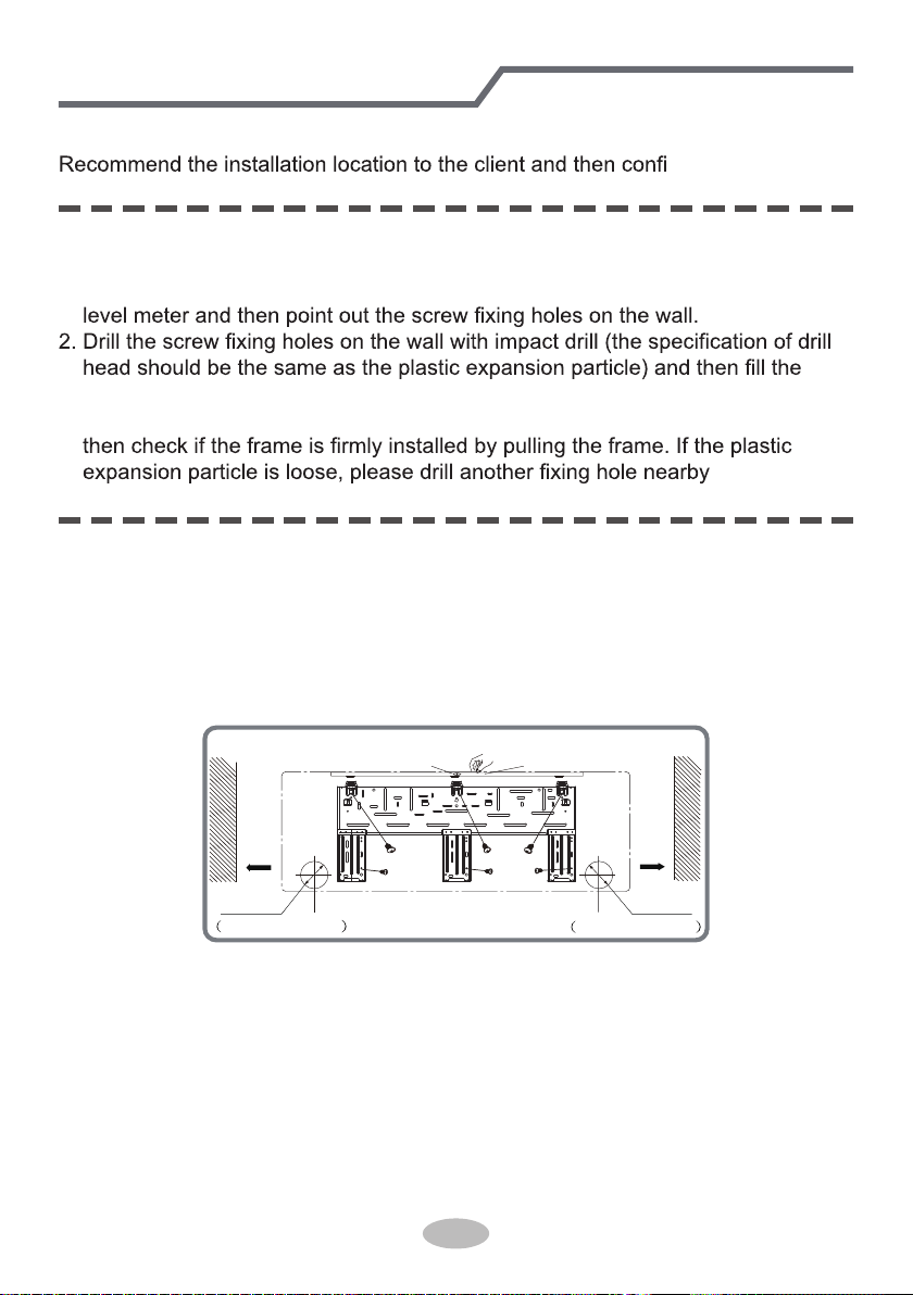
Step two: install wall-mounting frame
rm it with the client.
1. Hang the wall-mounting frame on the wall; adjust it in horizontal position with the
plastic expansion particles in the holes.
3. Fix the wall-mounting frame on the wall with tapping screws (ST4.2X25TA) and
.
1. Choose the position of piping hole according to the direction of outlet pipe. The
position of piping hole should be a little lower than the wall-mounted frame,
shown as below.
Step three: open piping hole
2. Open a piping hole with the diameter of Φ70 on the selected outlet pipe position.
In order to drain smoothly, slant the piping hole on the wall slightly downward to
the outdoor side with the gradient of 5-10°.
Left
Wall
Φ70mm
Right
Mark in the middle of it
Level meter
Rear piping hole
Wall
Space
to the
wall
above
150mm
Space
to the
wall
above
150mm
Φ70mm
Rear piping hole
27
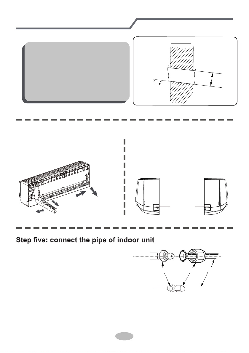
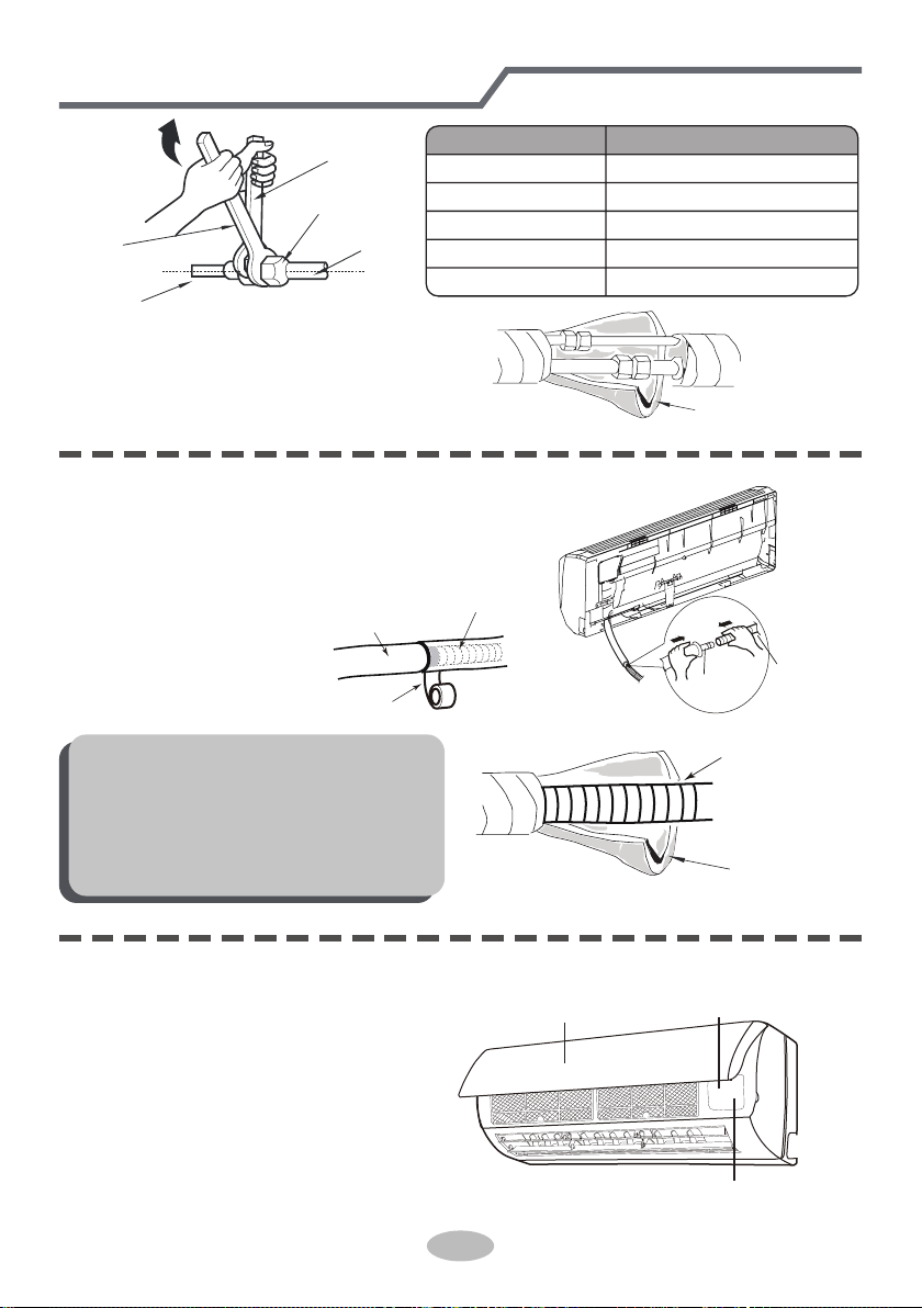
1. Aim the pipe joint at the corresponding
bellmouth.
2. Pretightening the union nut with hand.
3. Adjust the torque force by referring to the following sheet. Place the open-end
wrench on the pipe joint and place the torque wrench on the union nut. Tighten
the union nut with torque wrench.
2. When select leading out the pipe
from left or right, please cut off the
corresponding hole on the bottom
case.
cut off
the hole
left right
1. The pipe can be led out in the
direction of right, rear right, left or
rear left.
left
rear left
right
rear right
Step four: outlet pipe
Installation of indoor unit
Note:
● Pay attention to dust prevention and
take relevant safety measures when
opening the hole.
●
The plastic expansion particles are
not provided and should be bought
locally.
union nutpipe joint
pipe
Indoor
5-10
outdoor
Φ70
28
4. Wrap the indoor pipe and joint of con-
nection pipe with insulating pipe, and
then wrap it with tape.
Step six: install drain hose
Installation of indoor unit
torque wrench
open-end
wrench
indoor pipe
pipe
union nut
Hex nut diameter Tightening torque (N
.
m)
1/4"
3/8"
1/2"
5/8"
3/4"
30~40
45~55
60~65
70~75
15~20
insulating pipe
1. Connect the drain hose to the outlet pipe of
indoor unit.
2. Bind the joint with tape.
outlet
pipe
drain hose
drain hose
tape
outlet pipe
drain hose
insulating pipe
Note:
● Add insulating pipe in the indoor
drain hose in order to prevent
condensation.
● The plastic expansion particles are
not provided.
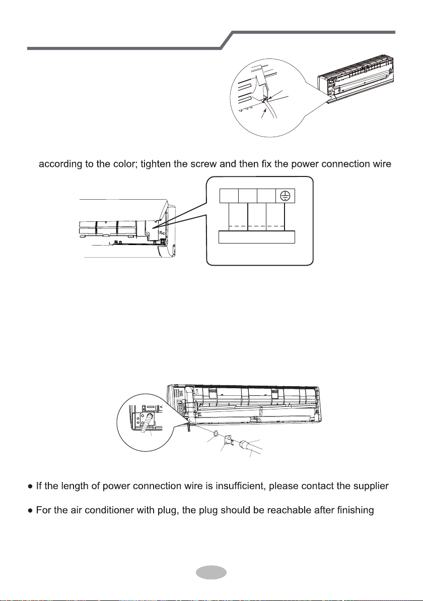
1. Open the panel, remove the screw
on the wiring cover and then take
down the cover.
screw
pane
wiring cover
Step seven: connect wire of indoor unit
29
Installation of indoor unit
3. Remove the wire clip; connect the power connection wire to the wiring terminal
with wire clip.
power connection
wire
cable-cross
hole
2. Make the power connection wire go
through the cable-cross hole at the back
of indoor unit and then pull it out from
the front side.
3
2
N(1)
Outdoor unit connection
green
green)
red
black
(yellow-
(brown)
white
(blue)
4. Put wiring cover back and then tighten the screw.
5. Close the panel.
6. Install the Conduit assy.
1) Fix the conduit assy on the conduit board and then let the connection wire
between indoor unit and outdoor unit go through the conduit.
2) Fix the conduit assy on the chassis with 3 screws.
● Conduit assy consists of conduit, conduit connector and lock nut.(Not the
standard part, which should be purchased by customer.)
● The length of conduit can be calculated according to the length of connection wire.
Note:
● All wires of indoor unit and outdoor unit should be connected by a professional.
for a new one. Avoid extending the wire by yourself.
installation.
● For the air conditioner without plug, an circuit break must be installed in the line.
The circuit break should be all-pole parting and the contact parting distance
should be more than 3mm.
Lock nut
Conduit connector
Cable Cross Plate
Conduit
connection wire
sleeve
30
Installation of indoor unit
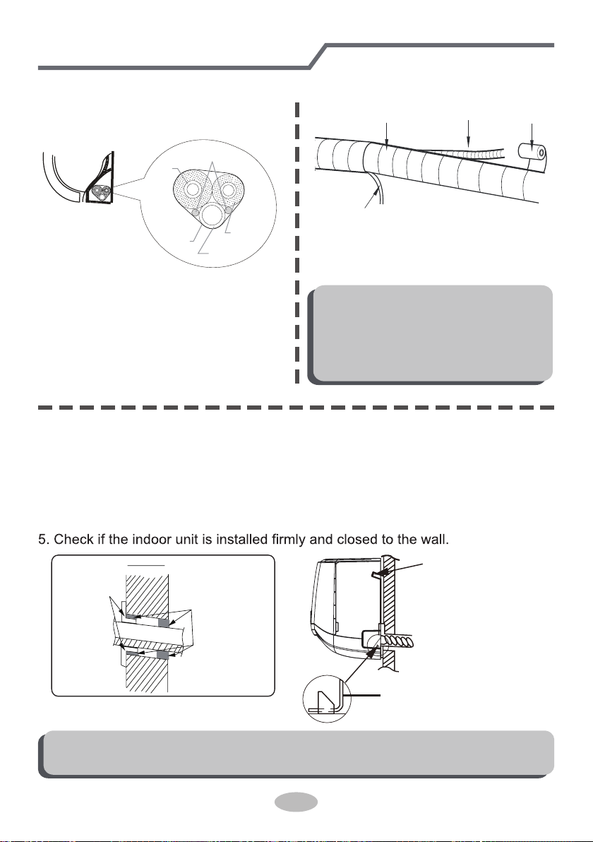
Step eight: bind up pipe
1. Bind up the connection pipe, power
cord and drain hose with the band.
indoor unit
gas
pipe
indoor and
outdoor power cord
liquid pipe
drain hose
band
2. Reserve a certain length of drain
hose and power cord for installation
when binding them. When binding to
a certain degree, separate the indoor
power and then separate the drain
hose.
3. Bind them evenly.
4. The liquid pipe and gas pipe should
be bound separately at the end.
Note:
● The power cord and control wire
can't be crossed or winding.
● The drain hose should be bound
at the bottom.
drain hose
band
connection pipe
indoor power cord
Step nine: hang the indoor unit
1. Put the bound pipes in the wall pipe and then make them pass through the wall
hole.
2. Hang the indoor unit on the wall-mounting frame.
3. Stuff the gap between pipes and wall hole with sealing gum.
4. Fix the wall pipe.
Note:
● Do not bend the drain hose too excessively in order to prevent blocking.
indoor
outdoor
wall pipe
sealing gum
upper hook
lower hook of
wall-mounting frame
31
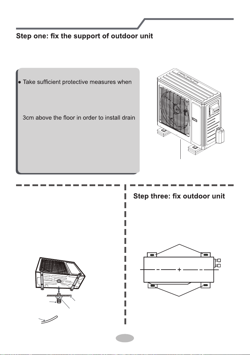
Installation of outdoor unit
(select it according to the actual installation situation)
1. Select installation location according to the house structure.
2. Fix the support of outdoor unit on the selected location with expansion screws.
at least 3cm above the floor
Note:
installing the outdoor unit.
●
Make sure the support can withstand at least
four times of the unit weight.
● The outdoor unit should be installed at least
joint.
● For the unit with cooling capacity of 2300W
~5000W, 6 expansion screws are needed;
for the unit with cooling capacity of 6000W
~8000W, 8 expansion screws are needed;
for the unit with cooling capacity of 10000W
~16000W, 10 expansion screws are needed.
Step two: install drain joint
gnitaehdnagniloocrofylnO(
unit)
1. Connect the outdoor drain joint into
the hole on the chassis, as shown in
the picture below.
2. Connect the drain hose into the drain
vent.
chassis
outdoor drain joint
Drain hose
drain vent
1. Place the outdoor unit on the
support.
2. Fix the foot holes of outdoor unit
with bolts.
foot holes
foot holes
32
Installation of outdoor unit
Step four: connect indoor and outdoor pipes
1. Remove the screw cap of valve and
aim the pipe joint at the bellmouth of
pipe.
2. Pretightening the union nut with
hand.
3. Tighten the union nut with torque
wrench by referring to the sheet
below.
gas pipe
liquid pipe
liquid
valve
gas valve
union nut
pipe joint
Hex nut diameter
Tightening torque
(N
.
m)
1/4"
3/8"
1/2"
5/8"
3/4"
30~40
45~55
60~65
70~75
15~20
Indoor unit connection
POWER
N(1) 2 3 L1
L1
L2 G
L2
(blue)
white
(blue)
whitered
black
(brown)
(brown)
black
(yellow-
green
green)
(yellow-
green
green)
lock nut
Finish
conduit
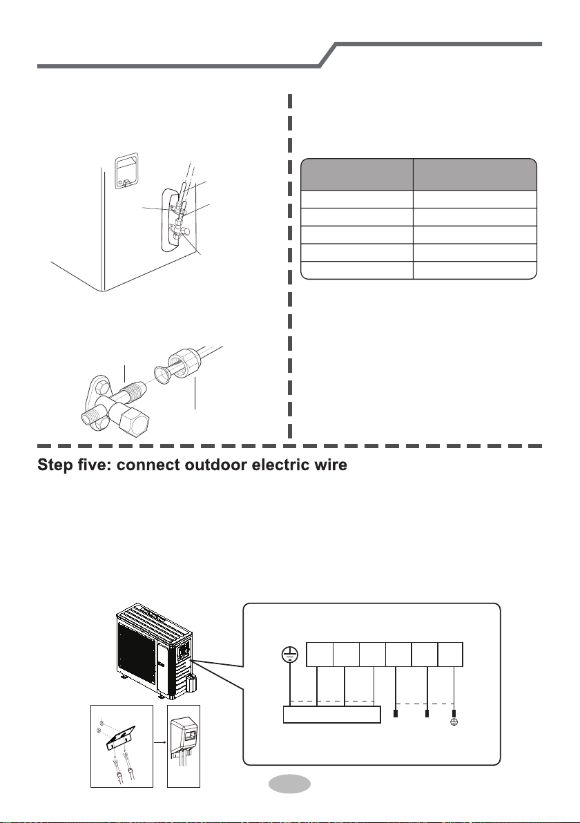
1. Remove the handle from the outdoor unit.
2. Fasten the power supply cord and the connection cord to the retaining plate using
the lock nut.(open the knock out holes if necessary)
3. Connect the power supply cord and the connection cord to terminal.
4. Fasten the power supply cord and connection cord with cord clamp.
5. Install the handle.
The screws are packed with the terminal board.
33
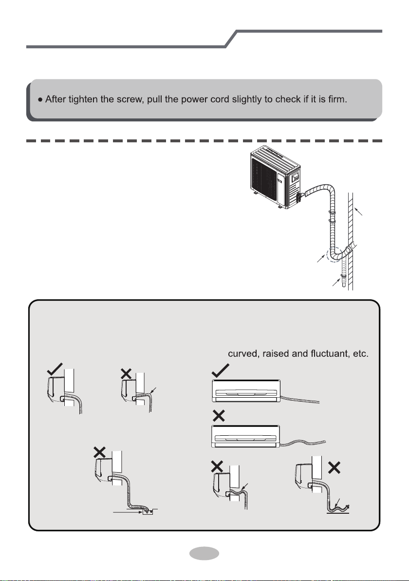
Step six: neaten the pipes
1. The pipes should be placed along the wall,
bent reasonably and hidden possibly. Min.
semidiameter of bending the pipe is 10cm.
2. If the outdoor unit is higher than the wall
hole, you must set a U-shaped curve in the
pipe before pipe goes into the room, in
order to prevent rain from getting into the
room.
● The through-wal height of drain hose
shouldn't be higher than the outlet
pipe hole of indoor unit.
● Slant the drain hose slightly dow-
nwards. The drain hose can't be
● The water outlet can't be placed
in water in order to drain smoothly.
Installation of outdoor unit
U-shaped curve
wall
drain hose
the drain hose
can't raise
upwards.
The drain hose can't be fluctuant
The drain hose
can't be fluctuant
The water
outlet can't be
fluctuant
The water outlet
can't be placed
in water
Note:
2. Fix the power connection wire and signal control wire with wire clip (only for
cooling and heating unit).
Note:
● Never cut the power connection wire to prolong or shorten the distance.
34
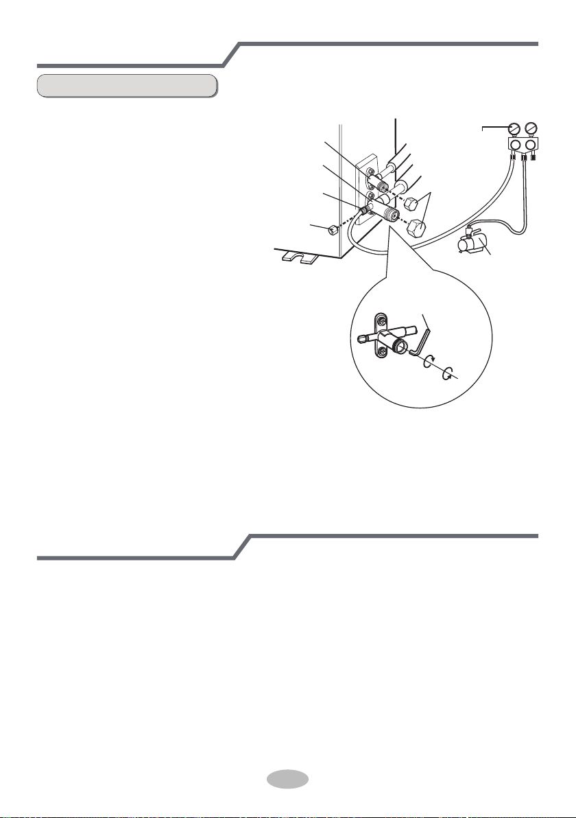
Vacuum pumping
Leakage detection
1. Remove the valve caps on
the liquid valve and gas
valve and the nut of refri-
gerant charging vent.
2. Connect the charging hose
of piezometer to the refri-
gerant charging vent of gas
valve and then connect the
other charging hose to the
vacuum pump.
3. Open the piezometer com-
pletely and operate for
10-15min to check if the
pressure of piezometer re-
mains in -0.1MPa.
4. Close the vacuum pump
and maintain this status for
1-2min to check if the pres-
sure of piezometer remains
in -0.1MPa. If the pressure decreases, there may be leakage.
5. Remove the piezometer, open the valve core of liquid valve and gas valve
completely with inner hexagon spanner.
6. Tighten the screw caps of valves and refrigerant charging vent.
7. Reinstall the handle.
Use vacuum pump
liquid valve
gas valve
refrigerant
charging vent
nut of refrigerant
charging vent
vacuum pump
piezometer
valve cap
Lo Hi
inner hexagon
spanner
open
close
1. With leakage detector:
Check if there is leakage with leakage detector.
2. With soap water:
If leakage detector is not available, please use soap water for leakage detection.
Apply soap water at the suspected position and keep the soap water for more
than 3min. If there are air bubbles coming out of this position, there's a leakage.
35
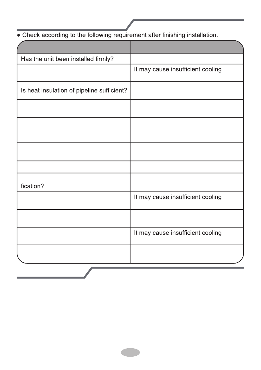
Check after installation
Test operation
Items to be checked Possible malfunction
The unit may drop, shake or emit noise.
Have you done the refrigerant leakage
test? (heating) capacity.
It may cause condensation and water
dripping.
Is water drained well?
It may cause condensation and water
dripping.
Is the voltage of power supply accord-
ing to the voltage marked on the
nameplate?
It may cause malfunction or damaging
the parts.
Is electric wiring and pipeline installed
correctly?
It may cause malfunction or damaging
the parts.
Is the unit grounded securely? It may cause electric leakage.
Does the power cord follow the speci-
It may cause malfunction or damaging
the parts.
Is there any obstruction in the air inlet
Is the inlet and outlet of piping hole
been covered?
and outlet?
(heating) capacity.
The dust and sundries caused during
installation are removed?
It may cause malfunction or damaging
the parts.
The gas valve and liquid valve of
connection pipe are open completely?
(heating) capacit
It may cause insufficient cooling
(heating) capacity or waster eletricity.
y.
1. Preparation of test operation
● The client approves the air conditioner.
● Specify the important notes for air conditioner to the client.
2. Method of test operation
● Put through the power, press ON/OFF button on the remote controller to start
operation.
● Press MODE button to select AUTO, COOL, DRY, FAN and HEAT to check
whether the operation is normal or not.
● If the ambient temperature is lower than 16
℃(61°F)
, the air conditioner can’t
start cooling.
Max length of connection pipe Unit: m
36
1. Standard length of connection pipe
● 5m, 7.5m, 8m.
4. The additional refrigerant oil and refrigerant charging required after prolonging
connection pipe
● After the length of connection pipe is prolonged for 10m at the basis of
standard length, you should add 5ml of refrigerant oil for each additional 5m
of connection pipe.
● The calculation method of additional refrigerant charging amount (on the basis
of liquid pipe):
● Basing on the length of standard pipe, add refrigerant according to the
requirement as shown in the table. The additional refrigerant charging amount
per meter is different according to the diameter of liquid pipe. See the
following sheet.
Additional refrigerant charging amount = prolonged length of liquid pipe ×
additional refrigerant charging amount per meter
2.Min. length of connection pipe is 3m.
3.Max. length of connection pipe.
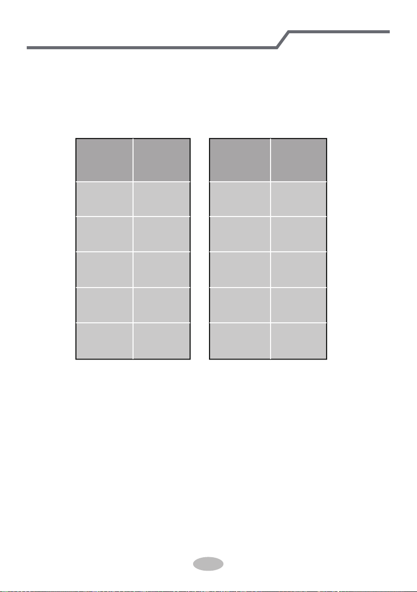
Configuration of connection pipe
15 25
15 30
15 30
20 30
25 30
Cooling
capacity
Max length
of connec-
tion pipe
Cooling
capacity
Max length
of connec-
tion pipe
5000Btu/h
(1465W)
7000Btu/h
(2051W)
9000Btu/h
(2637W)
12000Btu/h
(3516W)
18000Btu/h
(5274W)
24000Btu/h
(7032W)
28000Btu/h
(8204W)
36000Btu/h
(10548W)
42000Btu/h
(12306W)
48000Btu/h
(14064W)
37
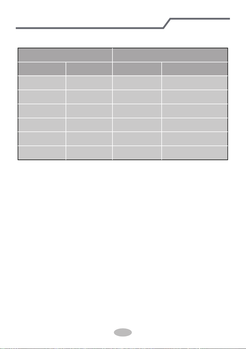
Additional refrigerant charging amount for R22, R407C, R410A and R134a
Diameter of connection pipe
Liquid pipe(in) Gas pipe(in)
1/4"
1/4" or 3/8"
1/2"
5/8"
3/4"
7/8"
3/8" or 1/2"
5/8" or 3/4"
3/4"or 7/8"
1" or 1-1/4"
_
_
Cooling only(oz/ft) Cooling and heating(oz/ft)
.16
.16
.32
.65
2.7 2.7
3.83.8
1.3
1.3
.54
.22
Outdoor unit throttle
Configuration of connection pipe
38
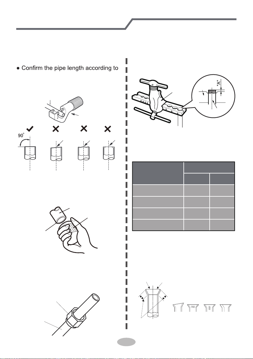
Pipe expanding method
Note:
Improper pipe expanding is the main cause of refrigerant leakage. Please expand
the pipe according to the following steps:
A: Cut the pipe
the distance of indoor unit and
outdoor unit.
● Cut the required pipe with pipe cutter.
pipe
pipe cutter
leaning uneven burr
B: Remove the burrs
● Remove the burrs with shaper and
prevent the burrs from getting into
the pipe.
downwards
pipe
shaper
C: Put on suitable insulating pipe
D: Put on the union nut
● Remove the union nut on the indoor
connection pipe and outdoor valve;
install the union nut on the pipe.
union pipe
pipe
E: Expand the port
● Expand the port with expander.
Note:
● "A" is different according to the
diameter, please refer to the sheet
below:
expander
hard
mold
pipe
F: Inspection
● Check the quality of expanding port.
If there is any blemish, expand the
port again according to the steps
above.
the length is equal
improper expanding
leaning
damaged
surface
crack uneven
thickness
smooth surface
Outer diameter
(mm)
A(in)
Max Min
Φ6-6.35(1/4")
Φ9.52(3/8")
Φ12-12.7(1/2")
Φ15.8-16(5/8")
3/64 1/32
1/16 3/64
5/64
3/64
3/32 3/32
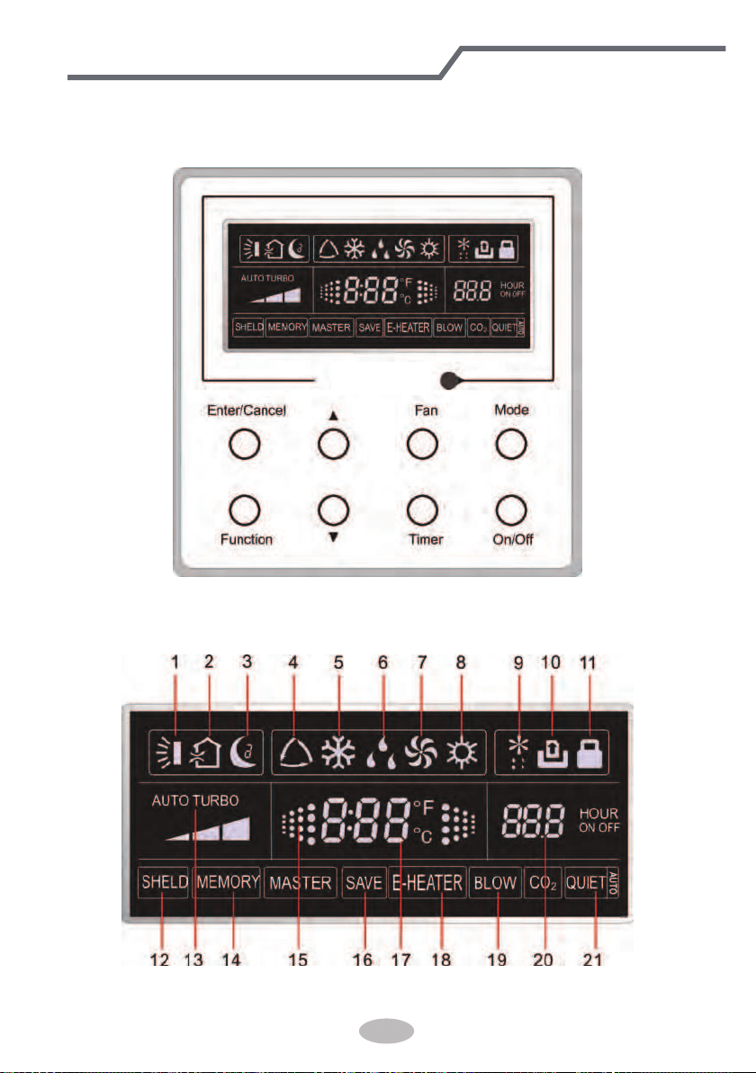
1 Displaying Part
Fig1.1.1 Outline of wired controller
1.1 LCD Display of Wired Controller
Fig.1.1.2 LCD display
39
If the product you bought is equipped with wired controller, please
refer to the following introductions of wired controller.
Wired Controller(Optional)
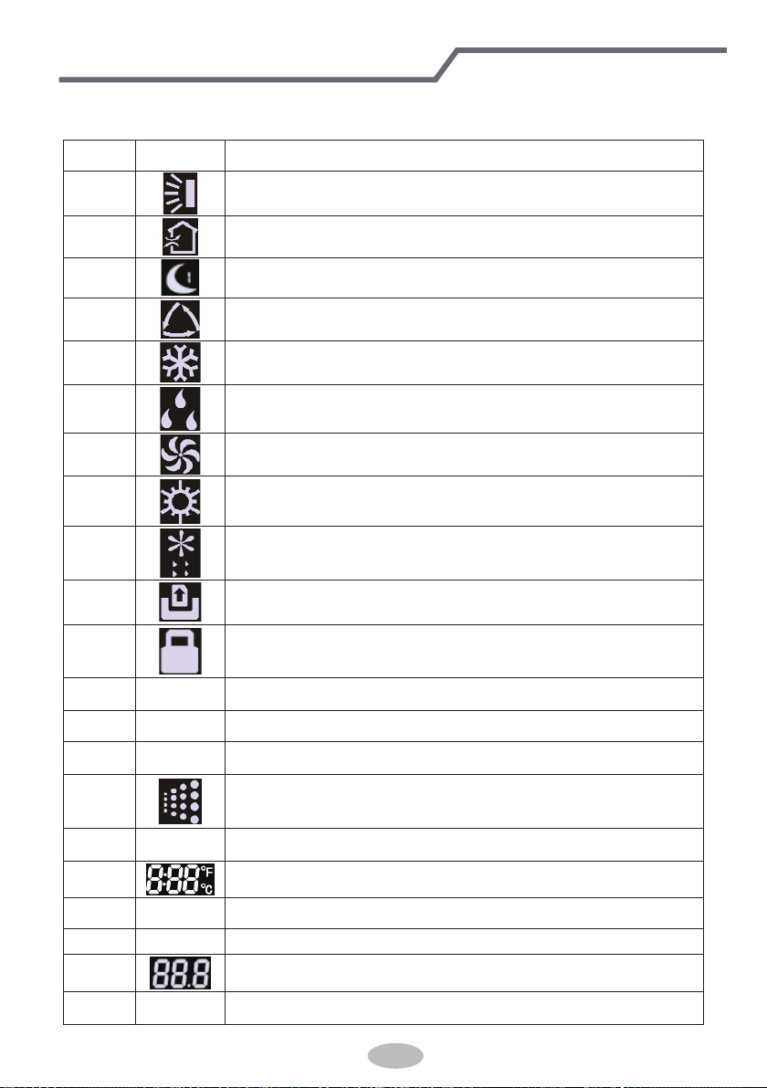
1.2 Instruction to LCD Display
Table 1.1
No. Symbols Description
1
Swing function
2
Air exchange function (this function is yet unavailable for this unit).
3
Sleep function (Only sleep 1).
4
Each kind of running mode of indoor unit (auto mode)
5
Cooling mode
6
Dry mode
7
Fan mode
8
Heating mode
9
Defrosting function for the outdoor unit.
10
Gate-control function (this function is yet unavailable for this unit).
11
Lock function.
12 SHIELD
Shield functions (Button operation, temperature setting, On/Off operation,
Mode setting are disabled by the remote monitoring system.)
13 Turbo Turbo function state
14 MEMORY
Memory function (The indoor unit resumes the original setting state after
power failure and then power recovery).
15
It blinks under on state of the unit without operation of any button.
16
SAVE
Energy-saving function.
17
Ambient/setting temperature value
18 E-HEATER Electric auxiliary heating function (this function is yet unavailable for this unit).
19 BLOW Blow function.
20
Timing value.
21 QUIET Quiet function (two types: quiet and auto quiet)
Wired Controller(Optional)
40
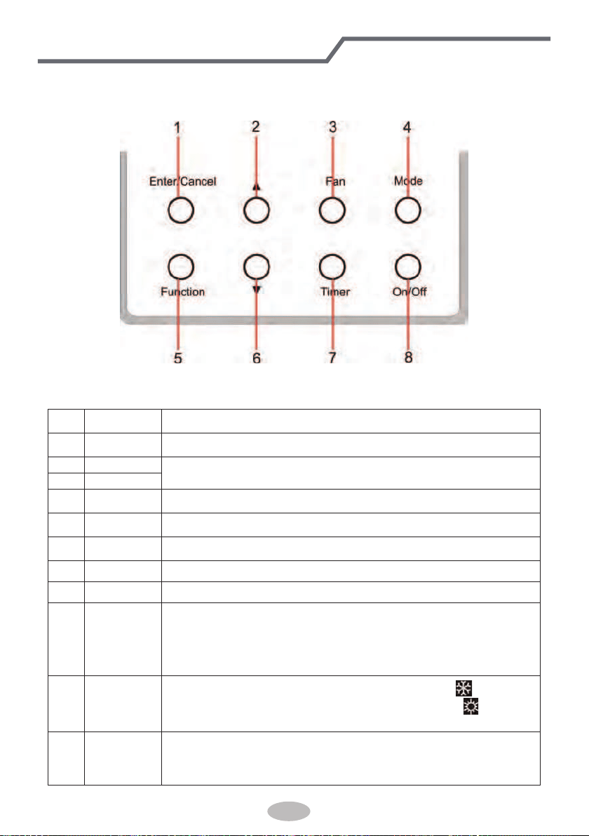
2 Buttons
2.1 Layout of Buttons
2.2 Functions of Buttons
Table 2.1
No. Name Function
1 Enter/Cancel Function selection and cancellation.
2 ▲
① .
Running temperature setting of the indoor unit, range:16~30
o
C.
② .
Timer setting, range:0.5-24 hr.
6 ▼
3 Fan Setting of the high/middle/low/auto fan speed.
4 Mode Setting of the Cooling/Heating/Fan/Dry/Auto mode of the indoor unit.
5 Function Switchover among the functions of Turbo/Save/E-heater/Blow etc..
7 Timer Timer setting.
8 On/Off Turn on/off the indoor unit
4+2 ▲+Mode
Press them for 5s under off state of the unit to enter/cancel the Memory
function(If memory is set, indoor unit after power failure and then power
recovery will resume the original setting state. If not, the indoor unit is
defaulted to be off after power recovery. Memory off is default before
delivery.).
3+6 Fan+▼
By pressing them at the same time under off state of the unit,
will be
displayed on the wired controller for the cooling only unit, while
will be
displayed on the wired controller for the cooling and heating unit.
2+6 ▲+▼
Upon startup of the unit without malfunction or under off state of the
unit,press them at the same time for 5s to enter the lock state, in which
case,any other buttons won’t respond the press. Repress them for 5s to quit
this state.
Wired Controller(Optional)
41
3 Operation Instructions
3.1 On/Off
Press On/Off to turn on the unit and turn it off by another press.
Note: The state shown in Fig.3.1.1 indicates the “Off” state of the unit after power on. The state
shown in Fig.3.1.2 indicates the “On” state of the unit after power on.
Fig.3.1.1 “Off” State Fig.3.1.2 “On” State
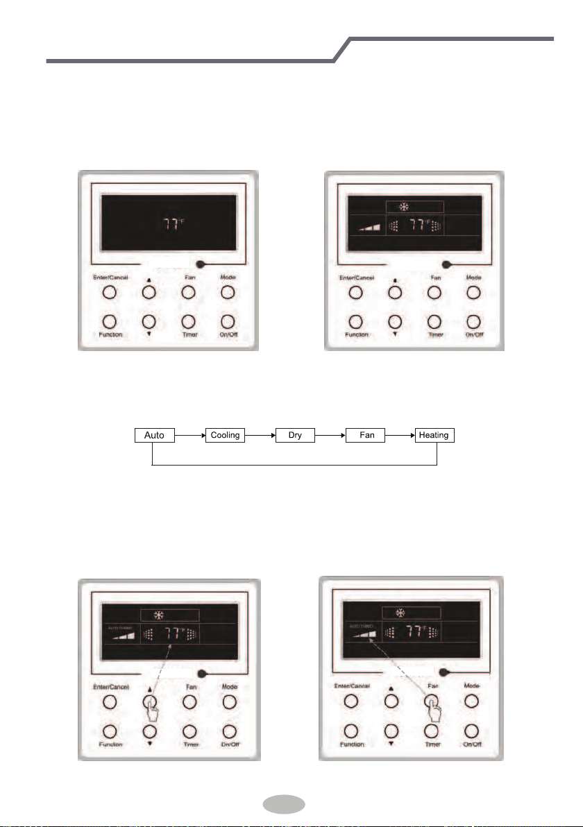
3.2 Mode Setting
Under ON state of the unit, press the Mode to switch the operation modes as the following
sequence: Auto–Cooling–Dry–Fan–Heating.
3.3 Temperature Setting
Press ▲or ▼ to increase/decrease the preset temperature. If pressing either of them
continuously, the temperature will be increased or decreased by 1°C every 0.5s,as shown in
Fig.3.3.1.
In the Cooling, Dry, Fan or Heating mode, the temperature setting range is 16°C~30°C.
In the Auto mode, the setting temperature is unadjustable.
Fig.3.3.1 Fig.3.4.1
42
Wired Controller(Optional)
3.4 Fan Setting
Under the “On” state of the unit, press Fan and then fan speed of the indoor unit will change
circularly as shown in Fig.3.4.1.
Low Middle
High
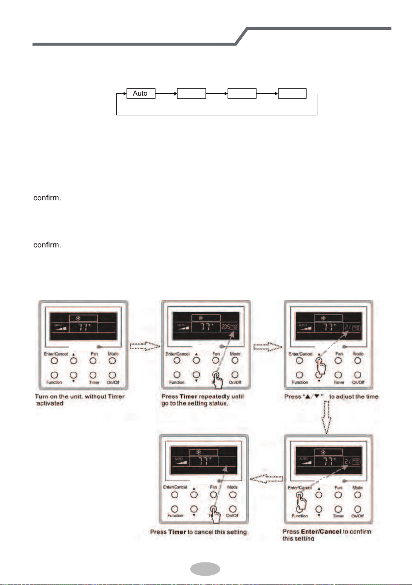
3.5 Timer Setting
Under on-state of the unit, Press Timer button to set timer off of the unit. Under off-state of the
unit, press Timer button to set timer on of the unit in the same way.
• Timer on setting:
Under off-state of the unit without timer setting, if Timer button is pressed, LCD will display xx.
Hour,with ON blinking. In this case, press▲ or ▼ button to adjust timer on and then press Timer to
• Timer off setting:
Under on-state of the unit without timer setting, if Timer button is pressed, LCD will display xx.
Hour,with OFF blinking. In this case, press▲ or ▼ button to adjust timer on and then press Timer to
• Cancel timer:
After setting of timer, if Timer button is pressed, LCD won’t display xx. Hour so that timer setting
is canceled.
Timer off setting under the “On” state of the unit is shown as Fig.3.5.1.
Fig.3.5.1 Timer off Setting under the “On”
State of the Unit
43
Wired Controller(Optional)
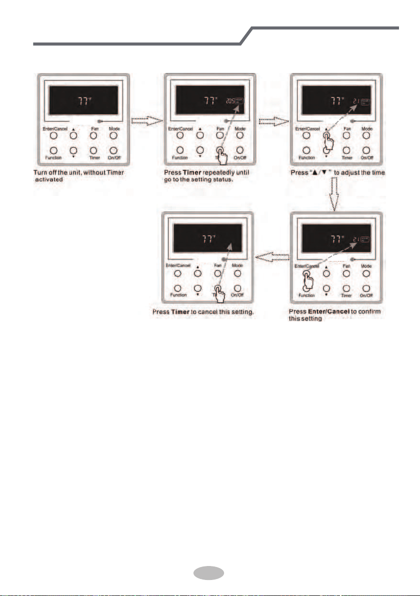
Timer on setting under the “Off” state of the unit is shown as Fig.3.5.2.
Fig.3.5.2 Timer on Setting under the “Off”
State of the Unit
Timer range: 0.5-24hr. Every press of ▲or ▼ will make the set time increased or decreased by
0.5hr. If either of them is pressed continuously, the set time will increase/ decrease by 0.5hr every
0.5s.
44
Wired Controller(Optional)
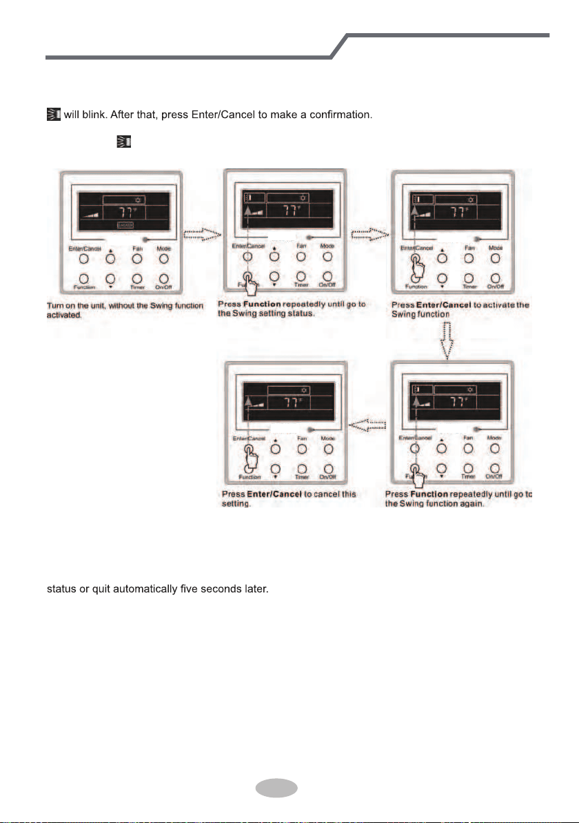
3.6 Swing Setting
Swing On: Press Function
under on state of the unit to activate the swing function. In this case,
Swing Off: When the Swing function is on, press Function to enter the Swing setting
interface,with
blinking. After that, press Enter/Cancel to cancel this function. Swing setting is
shown as Fig.3.6.1.
Fig.3.6.1 Swing Setting
Notes:
① .
Sleep, Turbo or Blow setting is the same as the Swing setting.
② .
After the setting has been done, it has to press the key “Enter/Cancel” to back to the setting
45
Wired Controller(Optional)
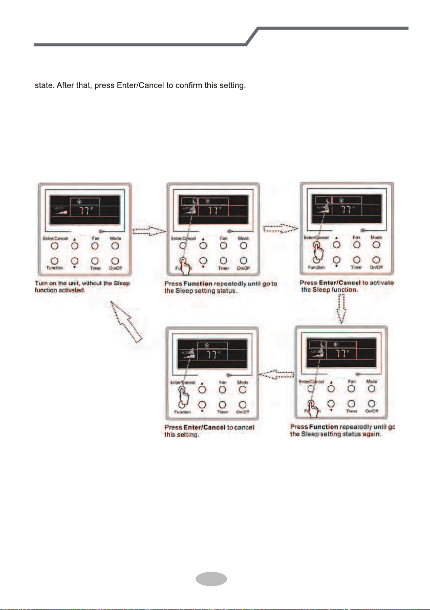
3.7 Sleep Setting
Sleep on: Press Function under the On state of the unit till the unit enters the Sleep setting
Sleep off: When the Sleep function is activated, press Function
to enter the Sleep setting
status. After that, press Enter/Cancel to cancel
this function.
In the Cooling or Dry mode, the temperature will increase by 1°C after the unit runs under
Sleep1 for 1hr and 1°C after another 1hr.After that, the unit will run at this temperature.
In the Heating mode, the temperature will decrease by 1°C after the unit runs under Sleep 1 for
1hr and 1°C after another 1hr. After that, the unit will run at this temperature.
Sleep setting is shown as Fig.3.7.1.
Fig.3.7.1. Sleep Setting
46
Wired Controller(Optional)
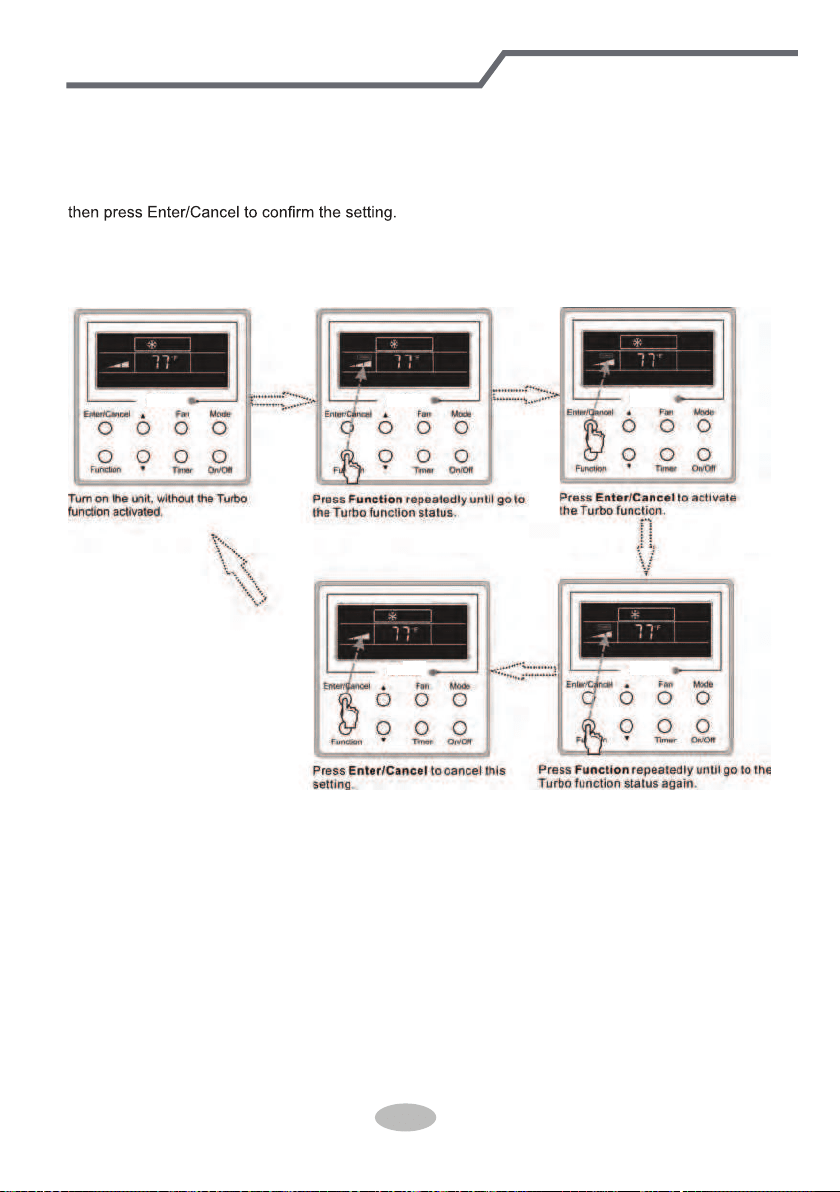
3.8 Turbo Setting
Turbo function: The unit at the high fan speed can realize quick cooling or heating so that the
room temperature can quickly approach the setting value.
In the Cooling or Heating mode, press Function
till the unit enters the Turbo setting status and
When the Turbo function is activated, press Function to enter the Turbo setting status and then
press Enter/Cancel
to cancel this function.
Turbo function setting is as shown in Fig.3.8.1.
Fig.3.8.1 Turbo Setting
47
Wired Controller(Optional)
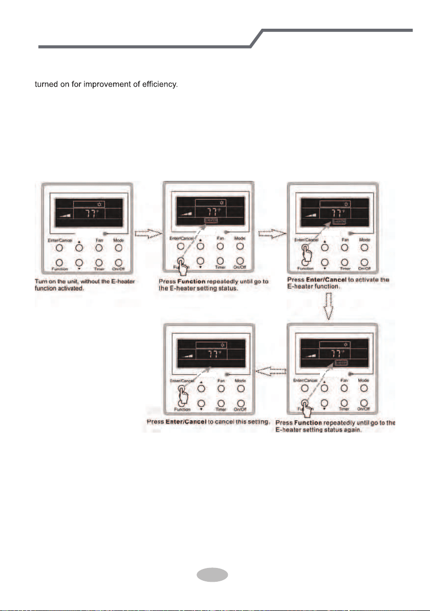
3.9 E-heater Setting
E-heater (auxiliary electric heating function): In the Heating mode, E-heater is allowed to be
Once the wired controller or the remote controller enters the Heating mode, this function will be
turned on automatically.
Press Function in the Heating mode to enter the E-heater setting interface and then press
Enter/Cancel to cancel this function.
Press Function
to enter the E-heater setting status, if the E-heater function is not activated,
and then press Enter/Cancel
to activate it.
The setting of this function is shown as Fig.3.9.1 below:
Fig.3.9.1 E-heater Setting
48
Wired Controller(Optional)
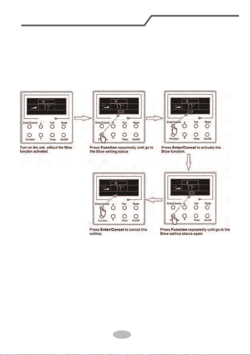
3.10 Blow Setting
Blow function: After the unit is turned off, the water in evaporator of indoor unit will be
automatically evaporated to avoid mildew.
In the Cooling or Dry mode, press Function
till the unit enters the Blow setting status and then
press Enter/Cancel
to active this function.
When the Blow function is activated, press Function
to the Blow setting status and then press
Enter/Cancel
to cancel this function.
Blow function setting is as shown in Fig.3.10.1
Fig.3.10.1 Blow Setting
Notes:
① .
When the Blow function is activated, if turning off the unit by pressing On/Off or by the
remote controller, the indoor fan will run at the low fan speed for 2 min, with “BLOW” displayed on
the LCD. While, if the Blow function is deactivated, the indoor fan will be turned off directly.
② .
Blow function is unavailable in the Fan or Heating mode.
49
Wired Controller(Optional)
3.11 Other Functions
a. Lock
Upon startup of the unit without malfunction or under the “Off” state of the unit, press ▲ and ▼ at
the same time for 5s till the wired controller enters the Lock function. In this case, LCD displays
.
After that, repress these two buttons at the same time for 5s to quit this function.
Under the Lock state, any other button press won’t get any response.
b. Memory
Memory switchover: Under the “Off” state of the unit, press Mode and ▲ at the same time for
5s to switch memory states between memory on and memory off. When this function is activated,
Memory will be displayed. If this function is not set, the unit will be under the “Off” state after power
failure and then power recovery.
Memory recovery: If this function has been set for the wired controller, the wired controller after
power failure will resume its original running state upon power recovery. Memory contents: On/
Off, Mode, set temperature, set fan speed and Lock function.
4 Installation and Dismantlement
4.1 Connection of the Signal Line of the Wired Controller
● Open the cover of the electric control box of the indoor unit.
● Let the single line of the wired controller through the rubber ring.
● Connect the signal line of the wired control to the 4-pin socket of the indoor unit PCB.
● Tighten the signal wire with ties.
● The communication distance between the main board and the wired controller can be up to
20 meters ( the standard distance is 8 meters)
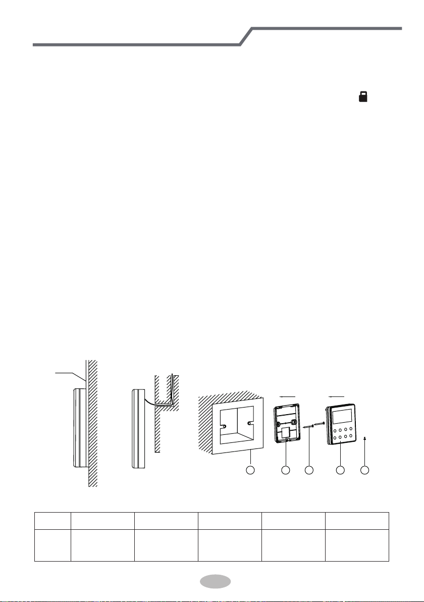
4.2 Installation of the Wired Controller
1
PVC Pipe
3 4 52
Fig.4.1 Accessories for the Installation of the Wired Controller
Table 4.1
No. 1 2 3 4 5
Name
Socket box
embedded
in the wall
Soleplate of
the Wired
Controller
Screw
M4X25
Front Panel
of the Wired
Controller
Screw
ST 2.9X6
Wired Controller(Optional)
50
1
6
8 9
10
7
3 4
5
2
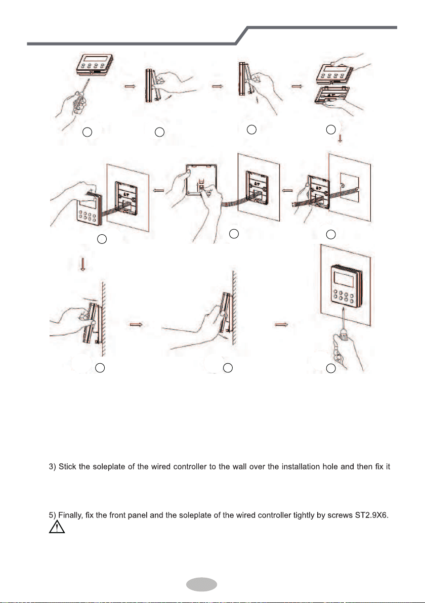
Fig.4.2
Fig.4.2 shows the installation steps of the wired controller, but there are some issues that need
your attention.
1) Prior to the installation, please firstly cut off the power supply of the wire buried in the
installation hole, that is, no operation is allowed with electricity during the whole installation.
2) Pull out the four-core twisted pair line from the installation holes and then let it go through
the rectangular hole behind the soleplate of the wired controller.
with screws M4X25.
4) Insert the four-core twisted pair line into the slot of the wired controller and then buckle the
front panel and the soleplate of the wired controller together.
CAUTION!
Please pay special attention to the followings during the connection to avoid the malfunction of
the air conditioning unit due to electromagnetic interference.
① .
Separate the signal and communication lines of the wired controller from the power cord
Wired Controller(Optional)
51
and connection lines between the indoor and outdoor unit, with a minimum interval of 20cm,
otherwise the communication of the unit will probably work abnormally.
② .
If the air conditioning unit is installed where is vulnerable to electromagnetic
interference,then the signal and communication lines of the wired controller must be the shielding
twisted pair lines.
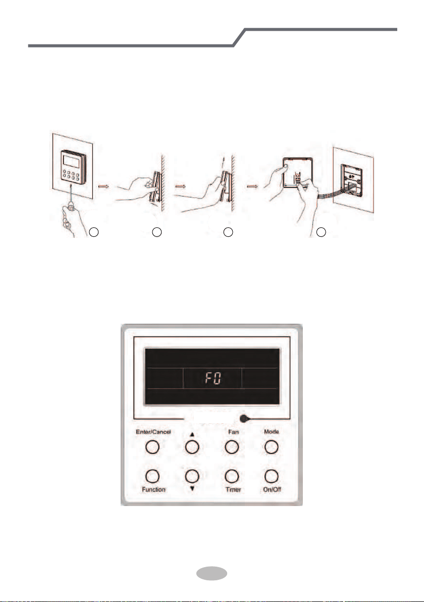
4.3 Dismantlement of the Wired Controller
1 3 42
5 Errors Display
If there is an error occurring during the operation of the system, the error code will be displayed
on the LCD, as show in Fig.5.1. If multi errors occur at the same time, their codes will be displayed
circularly.
Note: In event of any error, please turn off the unit and contact the professionally skilled
personnel.
Fig.5.1
Wired Controller(Optional)
52
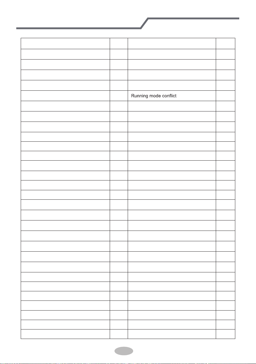
Table 5.1 Meaning of Each Error
Error
Error
Code
Error
Error
Code
Return air temperature sensor open/
short circuited
F1 Drive board communication error P6
evaporator temperature sensor open/
short circuited
F2 Compressor overheating protection H3
Indoor unit liquid valve temperature
sensor open/short circuited
b5 Indoor and outdoor units unmatched LP
Indoor gas valve temperature sensor
open/ short circuited
b7
Communication line misconnected or
expansion valve error
dn
IPM temperature sensor open/short
circuited
P7
E7
Outdoor ambient temperature sensor
open/ short circuited
F3 Pump-down Fo
Outdoor unit condenser mid-tube
temperature sensor open/short circuited
F4 Jumper error C5
Discharge temperature sensor open/
short circuited
F5 Forced defrosting H1
Indoor and outdoor communication error E6 Compressor startup failure Lc
DC bus under-voltage protection PL High discharge temperature protection E4
DC bus over-voltage protection PH Overload protection E8
Compressor phase current sensing
circuit error
U1 Whole unit over-current protection E5
Compressor demagnetization protection HE Over phase current protection P5
PFC protection Hc Compressor desynchronizing H7
IPM Temperature Protection P8 IPM Current protection H5
Over-power protection L9
Compressor phase loss/reversal
protection
Ld
System charge shortage or blockage
protection
F0
Frequency restricted/reduced with whole
unit current protection
F8
Capacitor charging error PU
Frequency restricted/reduced with IPM
current protection
En
High pressure protection E1
Frequency restricted/reduced with high
discharge temperature
F9
Low pressure protection E3
Frequency restricted/reduced with anti-
freezing protection
FH
Compressor stalling LE
Frequency restricted/reduced with
overload protection
F6
Over-speeding LF
Frequency restricted/reduced with IPM
temperature protection
EU
Drive board temperature sensor error PF Indoor unit full water error E9
AC contactor protection P9 Anti-freezing protection E2
Temperature drift protection PE AC input voltage abnormal PP
Sensor connection protection Pd Whole unit current sensing circuit error U5
DC bus voltage drop error U3 4-way valve reversing error U7
Outdoor fan 1 error protection L3 Motor stalling H6
Outdoor fan 2 error protection LA PG motor zero-crossing protection U8
Wired Controller(Optional)
53
GREE ELECTRIC APPLIANCES, INC. OF ZHUHAI
Add: West Jinji Rd, Qianshan, Zhuhai,Guangdong, China, 519070
Tel: (+86-756) 8522218
Fax: (+86-756) 8669426
E-mail: [email protected] www.greecomfort..com
66129931132
Cat No: GREE_LIVO+_C_INSTALL & OWNERS_36MBH_030119