Loading ...
Loading ...
Loading ...
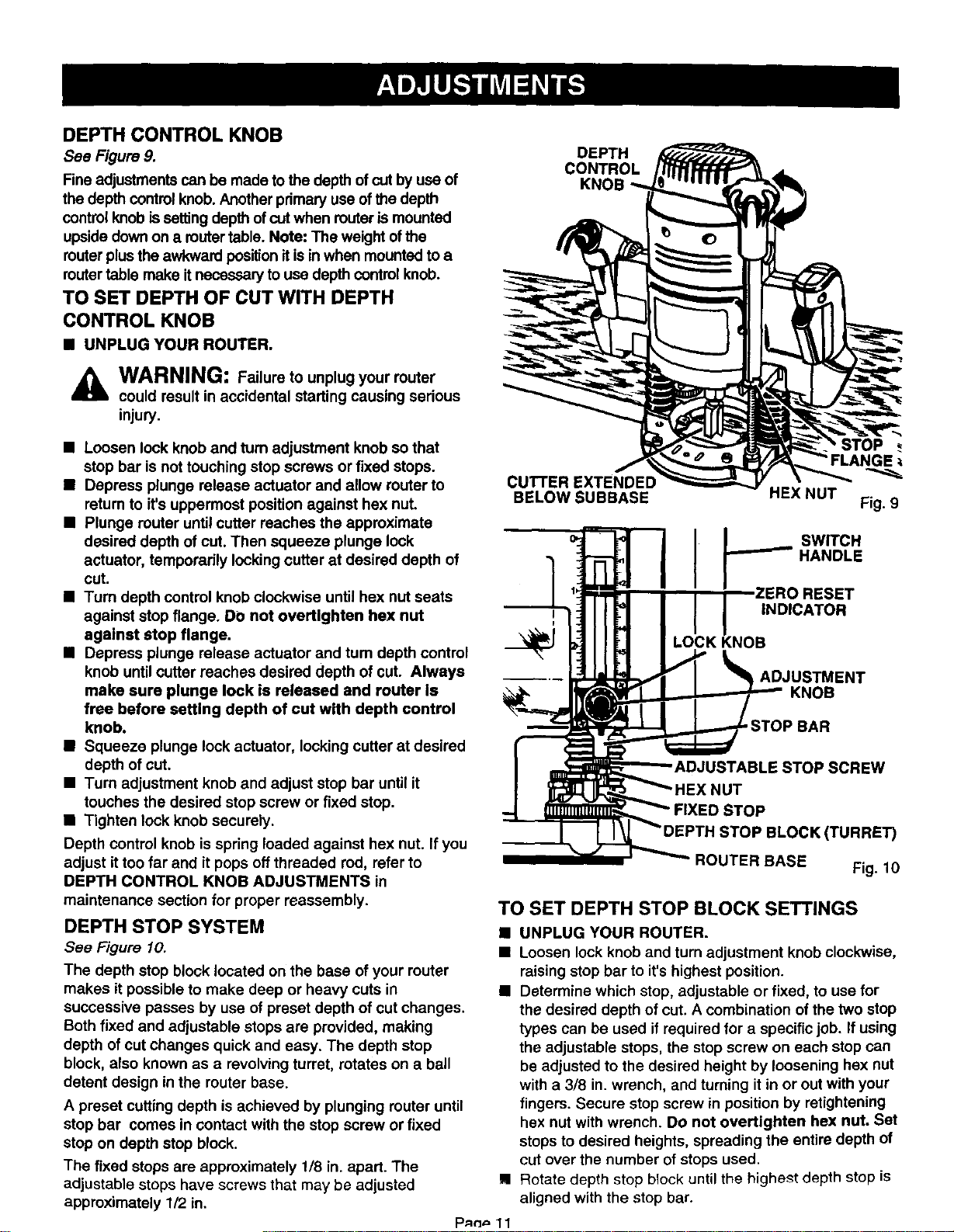
DEPTH CONTROL KNOB
See Figure 9.
Fine adjustments can be made to the depth of cut by use of
the depth controlknob. Anotherprimary use ofthe depth
controlknobis settingdepth ofcut when router is mounted
upside downon a router table. Note: The weight ofthe
router plusthe awkward positionit isin when mounted to a
router table make itnecessary touse depthcontrolknob.
TO SET DEPTH OF CUT WITH DEPTH
CONTROL KNOB
B UNPLUG YOUR ROUTER.
WARNING: Failure to unplug your router
could result in accidental starting causing serious
injury.
B Loosen lock knob and turn adjustment knob so that
stop bar is not touching stop screws or fixed stops.
• Depress plunge release actuator and allow router to
retum to it's uppermost position against hex nut.
• Plunge router until cutter reaches the approximate
desired depth of cut. Then squeeze plunge lock
actuator, temporarily lockingcutter at desired depth of
cut.
• Turn depth control knob clockwise until hex nut seats
against stop flange. DO not overtlghten hex nut
against stop flange.
• Depress plunge release actuator and turn depth control
knob until cutter reaches desired depth of cut. Always
make sure plunge lock is released and router Is
free before setting depth of cut with depth control
knob.
• Squeeze plunge lock actuator, locking cutter at desired
depth of cut.
• Turn adjustment knob and adjust stop bar until it
touches the desired stop screw or fixed stop.
• Tighten lock knob securely.
Depth control knob is spring loaded against hex nut. If you
adjust ittoo far and it pops off threaded rod, refer to
DEPTH CONTROL KNOB ADJUSTMENTS in
maintenance section for proper reassembly.
DEPTH STOP SYSTEM
See Figure 10.
The depth stop block located on the base of your router
makes it possible to make deep or heavy cuts in
successive passes by use of preset depth of cut changes.
Both fixed and adjustable stops are provided, making
depth of cut changes quick and easy. The depth stop
block, also known as a revolving turret, rotates on a ball
detent design in the router base.
A preset cutting depth is achieved by plunging router until
stop bar comes in contact with the stop screw or fixed
stop on depth stop block.
The fixed stops are approximately 1/8 in. apart. The
adjustable stops have screws that may be adjusted
approximately 1/2 in,
DEPTH
CONTROL
CUTTER EXTENDED
BELOW SUBBASE
I
I
STOP
HEX NUT
Fig. 9
SWITCH
HANDLE
ESET
INDICATOR
;K KNOB
ADJUSTMENT
KNOB
STOP BAR
E STOP SCREW
JT
D STOP
STOP BLOCK(TURRE_
ROUTER BASE Fig. 10
TO SET DEPTH STOP BLOCK SETTINGS
• UNPLUG YOUR ROUTER.
• Loosen lock knob and turn adjustment knob clockwise,
raisingstop bar to it's highest position.
• Determine which stop, adjustable or fixed, to use for
the desired depth of cut. A combination of the two stop
types can be used ifrequired for a specific job. If using
the adjustable stops, the stop screw on each stop can
be adjusted to the desired height by loosening hex nut
with a 3/8 in. wrench, and turning it in or out with your
fingers. Secure stop screw in position by retightening
hex nut with wrench. Do not overtighten hex nut. Set
stops to desired heights, spreading the entire depth of
cut over the number of stops used.
Rotate depth stop block until the highest depth stop is
aligned with the stop bar.
Loading ...
Loading ...
Loading ...