
INSTALLATION GUIDE
US CA
MINIMAL WB24SDEB2 & WB30SDEB1
CONTEMPORARY WB24SDEX2 & WB30SDEX1
PROFESSIONAL WB30SPEX1
WARMING DRAWER


3
CONTENTS
Safety and warnings 4
Warming drawer models 5
Unpack your product 6
Parts supplied 7
Tools required 7
Product dimensions - 24" minimal & contemporary models 8
Product dimensions - 30" minimal & contemporary models 9
Product dimensions - 30" professional models 10
Cabinetry dimensions - 24" minimal & contemporary models 11
Cabinetry dimensions - 30" minimal & contemporary models 12
Cabinetry dimensions - 30” professional models 13
Installation options 14
Installing the drawer 16
Adjusting the depth 17
Adjusting the height 17
Installer checklist 18
4
SAFETY AND WARNINGS
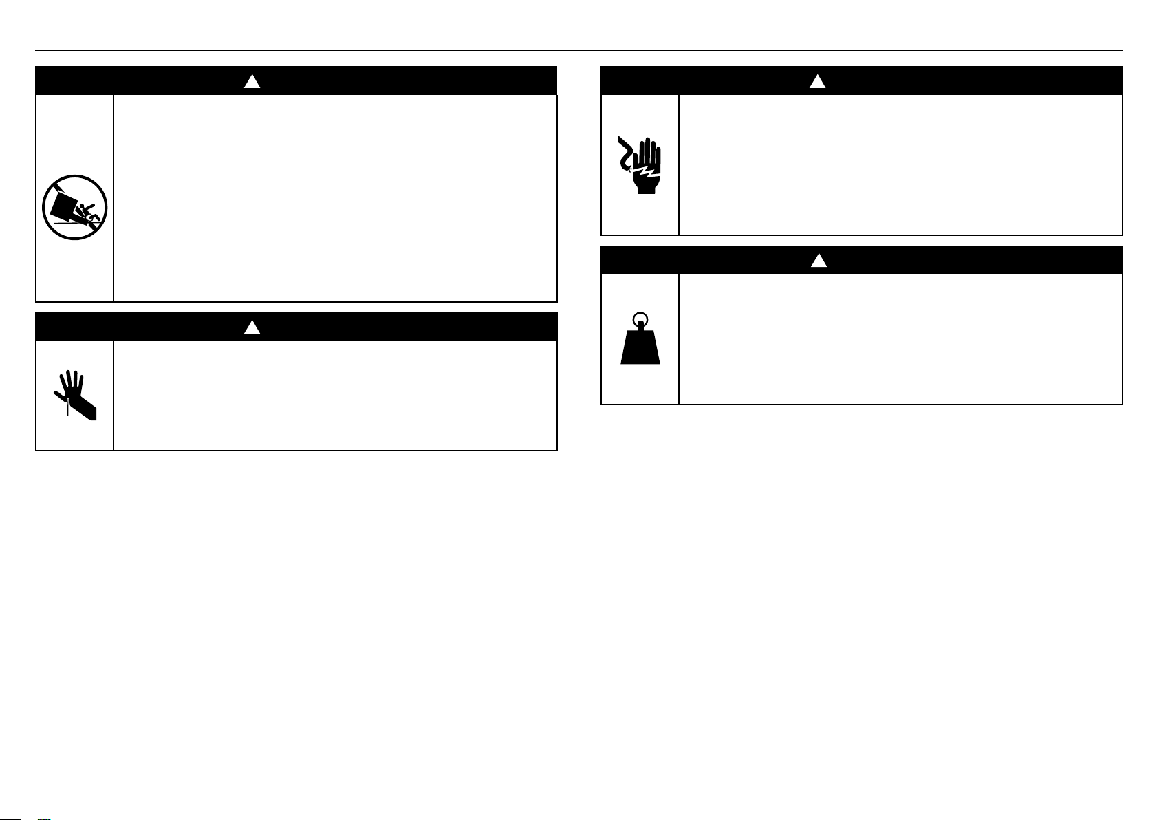
!
WARNING!
Tip Hazard
This product may tip. Keep children away and
take care. Failure to follow this advice may
result in injury.
• Drawer must be secured in place by supplied
screws.
• Ensure there is a fixed shelf directly above
the drawer if it is not installed under another
product.
!
WARNING!
Cut Hazard
Failure to use caution could result in injury.
• Take care: some edges may be sharp.
• Do not put fingers in the drawer when closing.
!
WARNING!
Electric Shock Hazard
Failure to follow this advice may result in
electrical shock or death.
• If the product is damaged, switch the appliance
off and disconnect it from the mains to avoid
possible electric shock.
!
WARNING!
420-630 lb
190-285 kg
Weight Hazard
Failure to follow this advice may result in
damage or personal injury.
• Ensure the bottom shelf of the cabinetry can fully
support the weight of combined appliances.
5
SAFETY AND WARNINGS WARMING DRAWER MODELS
READ AND SAVE THIS GUIDE
WARNING!
To reduce the risk of fire, injury to persons or damage when using the appliance, follow the
important safety guides listed below. Read all the instructions before using the appliance.
Installation
z
Please make this information available to the person installing the product.
z
The appliance must be installed by a qualified installer, or Fisher & Paykel trained and
supported service technician to avoid faulty electrical connection.
z
Ensure the installation complies with all clearance requirements and applicable standards
and regulations.
z
When installed in combination with a companion product, the companion product can be
placed directly onto the appliance. A built-in shelf at the base of the cabinetry must be
able to support the weight of both products.
z
Ensure the cabinetry is square and level and with correct dimensions.
z
If installing the appliance directly underneath an oven, ensure you do not damage the
oven’s lower trim. Fisher & Paykel does not accept any responsibility for any damage
resulting from incorrect installation.
z
Before installing the appliance, inspect for any signs of damage. Do not install or use
damaged appliances.
z
Be careful when stacking the appliances on top of each other to avoid damage to the
appliances.
Electrical
z
All connections for electrical power and earthing must be done by a qualified electrician
and must comply with local codes and ordinances.
z
Before installation, ensure that the voltage and frequency listed on the data plate
corresponds with the household electrical supply.
z
When combining with another appliance, ensure each appliance has its own power outlet.
Avoid sharing the power point to prevent accidental switching off of the appliance.
z
Ensure your appliance is properly grounded (earthed).
z
Connect the drawer to a properly rated, protected and sized power supply circuit to avoid
electrical overload.
z
Do not use an extension cord or a portable electrical outlet device (e.g. multi-outlet outlet
box) to connect the drawer to the power supply. Ensure the power supply cord is located
so that it will not be stepped on, tripped over or otherwise subject to damage or stress.
z
Ensure there is a switched outlet in an easily accessible area within 35 7/16” (900mm) of
the centre rear of the product.
Servicing
z
Do not repair or replace any part of the appliance unless specifically recommended in the
user guide. All other servicing should be done by a Fisher & Paykel trained and supported
service technician or qualified person.
z
Always disconnect the power supply before doing any installation, maintenance or repair
work, and cleaning.
z
If the power supply cord is damaged, it must be replaced by a qualified electrician or
Fisher & Paykel trained and supported service technician.
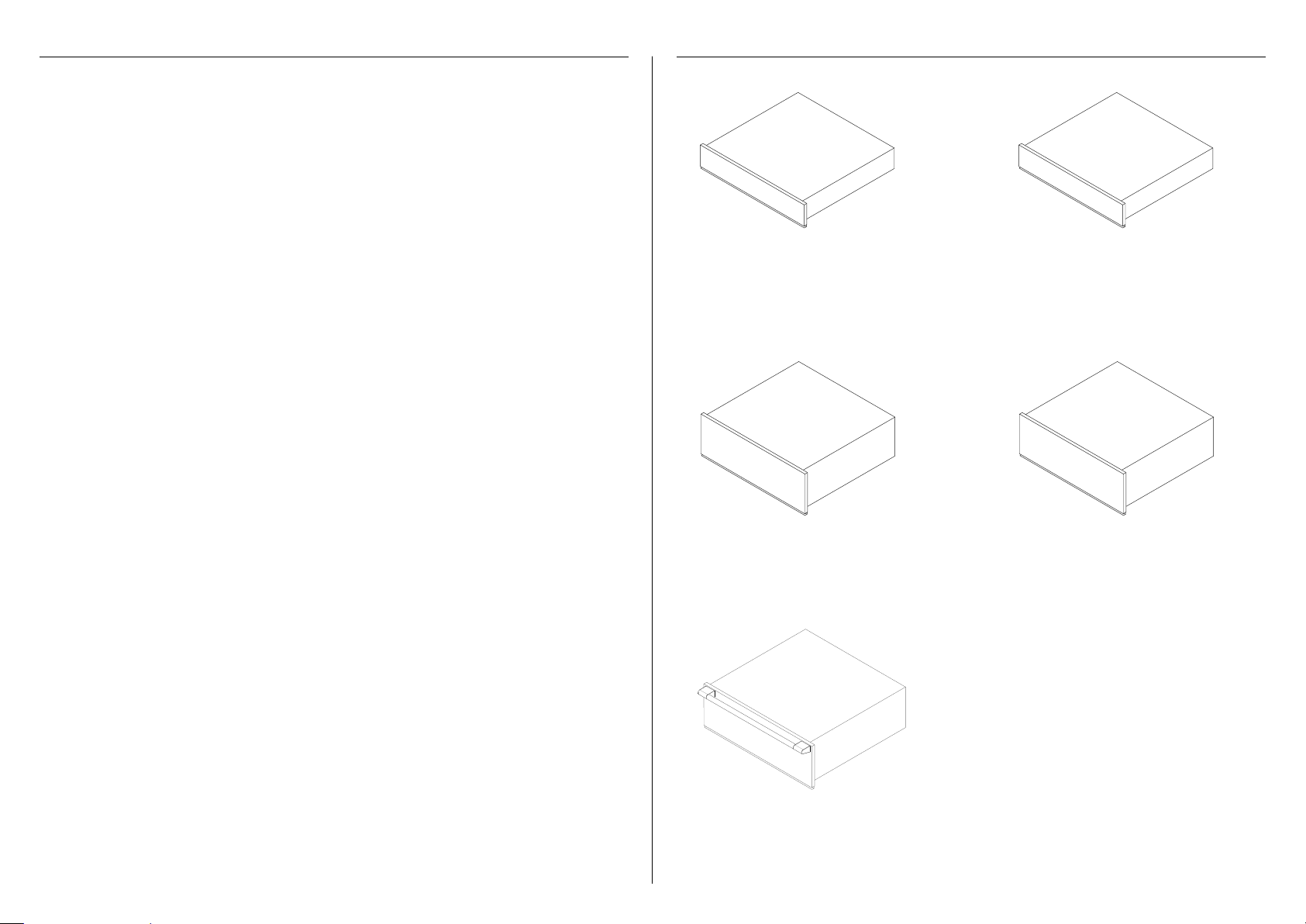
24" Warming Drawer,
Minimal style
WB24SDEB2
24" Warming Drawer,
Contemporary style
WB24SDEX2
30" Warming Drawer,
Minimal style
WB30SDEB1
30" Warming Drawer,
Contemporary style
WB30SDEX1
30" Warming Drawer,
Professional style
WB30SPEX1
6
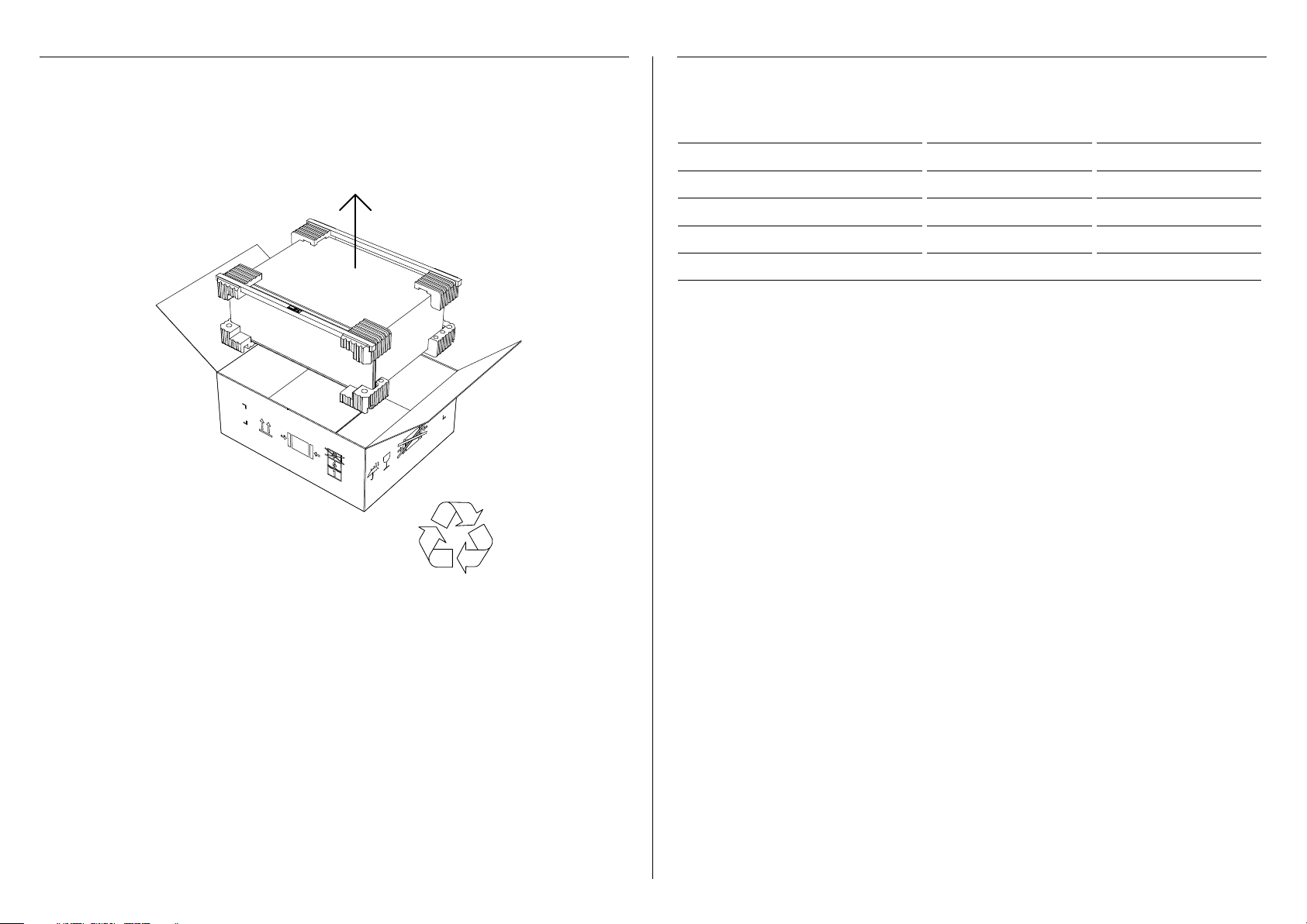
Remove the warming drawer and accessories box from the packaging. Recycle the materials
that can be reused. Dispose packaging materials in accordance with local regulations on waste
disposal.
Inspect the warming drawer for any signs of damage. Do not install the warming drawer if it
has been damaged. If the product is damaged, contact your local Fisher & Paykel dealer.
UNPACK YOUR PRODUCT ELECTRICAL SPECIFICATIONS
RECYCLE
RESPONSIBLY
All electrical work must be done by a qualified electrician, or a Fisher & Paykel trained and
supported service technician.
WB24 WB30
Supply 110 VAC, 60 Hz 110 VAC, 60 Hz
Service 10 amp circuit 10 amp circuit
Maximum Power 810 W 810 W
Power outlet* 3-prong grounding-type 3-prong grounding-type
Power cord (total length) 70 7/8" (1800mm) 70 7/8" (1800mm)
* The power outlet must be earthed and located within 35 7/16” (900mm) of the centre rear of the product.

7
Wire shelf (1)
For WB30 models only
Installation guideService & Warranty
SERVICE & WARRANTY
SERVICE ET GARANTIE
ΣΈΡΒΙΣ ΚΑΙ ΕΓΓΎΗΣΗ
SERVIZIO E GARANZIA
SERVICE & GARANTIE
HUOLTO JA TAKUU
SERVICE OG GARANTI
保修和维修
服務和保修
INSTALLATION GUIDE
US CA
MINIMAL WB24SDEB & WB30SDEB
CONTEMPORARY WB24SDEX & WB30SDEX
PROFESSIONAL WB30SPEX
WARMING DRAWER
User guide
USER GUIDE
US CA
WARMING DRAWER
MINIMAL WB24SDEB & WB30SDEB
CONTEMPORARY WB24SDEX & WB30SDEX
PROFESSIONAL WB30SPEX
iNTEGRATED WB30SDEI
5mm Hex key T20 star-head screwdriver
PARTS SUPPLIED TOOLS REQUIRED
T20 star head
countersunk screw 4x20
4 for WB30 models
2 for WB24 models
8
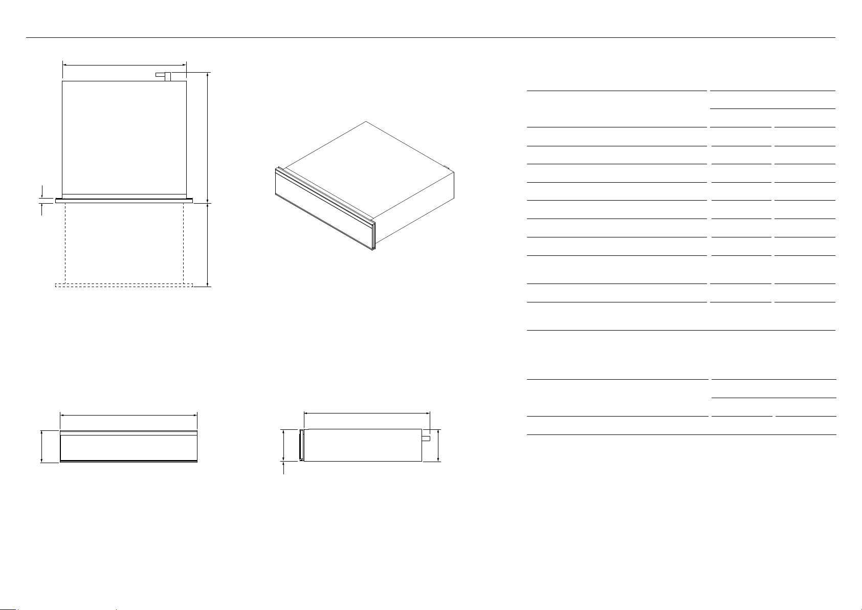
PRODUCT DIMENSIONS - 24" MINIMAL & CONTEMPORARY MODELS
C
i
h
E
PLAN
ISOMETRIC
FRONT
B
A
PROFILE
D
G
F
j
Actual product dimension may vary by ± 1/16" (2 mm).
PRODUCT DIMENSIONS
WB24SD
IN MM
A Overall height 5 1/2 140
B Overall width 23 7/16 596
C Overall depth* 22 5/16 567
D Height of chassis 5 1/2 140
E Width of chassis 21 3/8 543
F Depth of chassis** 21 9/16 547
G Height of drawer front panel 5 3/8 136
H Depth of drawer front panel and
attachment flange
13/16 20
I Depth of open drawer 16 5/16 414
J Height from bottom of chassis to
bottom of drawer front panel
1/16 2
* Including drawer front panel and power plug
** Including power plug
PRODUCT WEIGHT
WB24SD
LBS KG
Total weight of drawer* 48 22
*including packaging
9
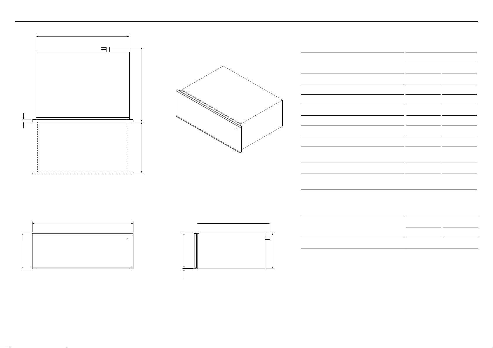
PRODUCT DIMENSIONS - 30" MINIMAL & CONTEMPORARY MODELS
G
j
D
F
PROFILE
h
PLAN
c
E
i
FRONT
a
b
ISOMETRIC
Actual product dimension may vary by ± 1/16" (2 mm).
PRODUCT DIMENSIONS
WB30SD
IN MM
A Overall height 10 11/16 271
B Overall width 29 15/16 761
C Overall depth* 22 5/16 567
D Height of chassis 10 11/16 271
E Width of chassis 27 13/16 707
F Depth of chassis** 21 9/16 547
G Height of drawer front panel 10 1/2 267
H Depth of drawer front panel and
attachment flange
13/16 20
I Depth of open drawer 16 1/2 419
J Height from bottom of chassis to
bottom of drawer panel
1/16 2
* Including drawer panel and power plug
** Including power plug
PRODUCT WEIGHT
WB30SD
LBS KG
Total weight of drawer* 75 34
*including packaging
10
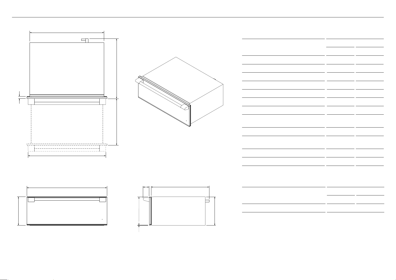
PRODUCT DIMENSIONS - 30" PROFESSIONAL MODELS
Actual product dimension may vary by ± 1/16" (2 mm).
PRODUCT DIMENSIONS
WB30SP
IN MM
A Overall height 10 11/16 271
B Overall width 29 15/16 761
C Overall depth* 22 3/8 568
D Height of chassis 10 11/16 271
E Width of chassis 27 3/4 704
F Depth of chassis** 21 9/16 548
G Height of drawer front panel 10 1/2 267
H Depth of drawer front panel and
attachment flange
13/16 20
I Depth of open drawer 16 1/2 419
J Height from bottom of chassis to
bottom of drawer panel
1/16 2
K Width of handle 29 736
L Depth of handle 2 1/4 58
* Including drawer panel and power plug
** Including power plug
PRODUCT WEIGHT
WB30SP
LBS KG
Total weight of drawer* 75 34
*including packaging and excluding handle
B
a
FRONT
e
c
h
i
PLAN
d
f
PROFILE
ISOMETRIC
j
g
l
k
11
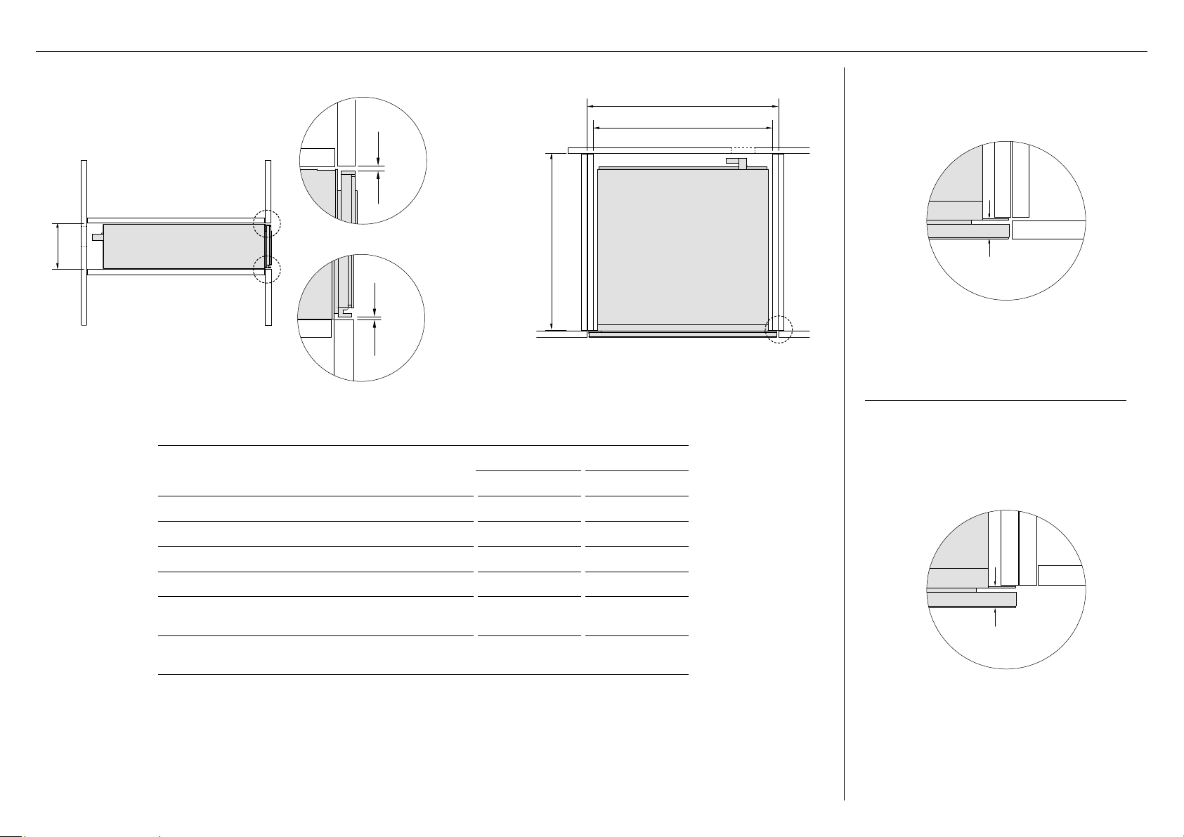
CABINETRY DIMENSIONS - 24" MINIMAL & CONTEMPORARY MODELS
PROUD INSTALL
FLUSH INSTALL
PLAN
c
b
d
PO*
PROFILE
a
PO*
e
f
CABINETRY DIMENSIONS
WB24SD
INCHES MM
A Minimum inside height of cavity 5 9/16 142
B Minimum inside width of cavity 22 1/16 560
C Minimum inside depth of cavity 22 1/2 572
D Overall width of cabinetry 23 5/8 600
E Minimum clearance between top of front panel
and upper cabinetry panel
1/8 3
F Minimum clearance between bottom of front
panel and lower cabinetry panel
1/16 2
* The power outlet (PO) must be earthed and located within 35 7/16” (900mm) of the centre rear of the product.
Actual product dimension may vary by ± 1/16" (2 mm).
13/16 (20mm)*
13/16 (20mm)*
* Depth of drawer front panel including attachment flange.
12
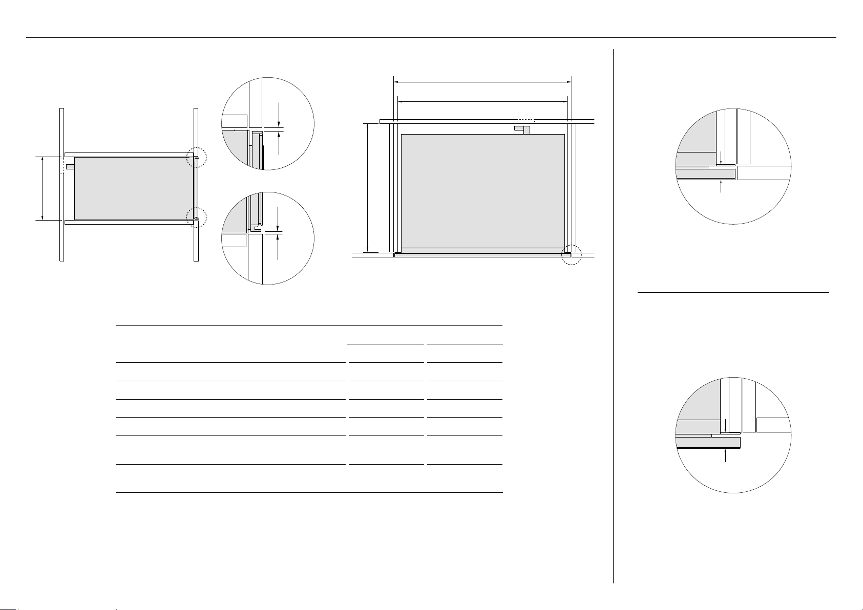
CABINETRY DIMENSIONS - 30" MINIMAL & CONTEMPORARY MODELS
PROUD INSTALL
FLUSH INSTALL
PLAN
c
b
d
PO*
a
PROFILE
PO*
e
f
CABINETRY DIMENSIONS
WB30SD
INCHES MM
A Minimum inside height of cavity 10 3/4 273
B Minimum inside width of cavity 28 1/2 724
C Minimum inside depth of cavity 22 1/2 572
D Overall width of cabinetry 30 762
E Minimum clearance between top of front panel
and upper cabinetry panel
1/8 3
F Minimum clearance between bottom of front
panel and lower cabinetry panel
1/16 2
* The power outlet (PO) must be earthed and located within 35 7/16” (900mm) of the centre rear of the product.
Actual product dimension may vary by ± 1/16" (2 mm).
13/16 (20mm)*
13/16 (20mm)*
* Depth of drawer front panel including attachment flange.
13
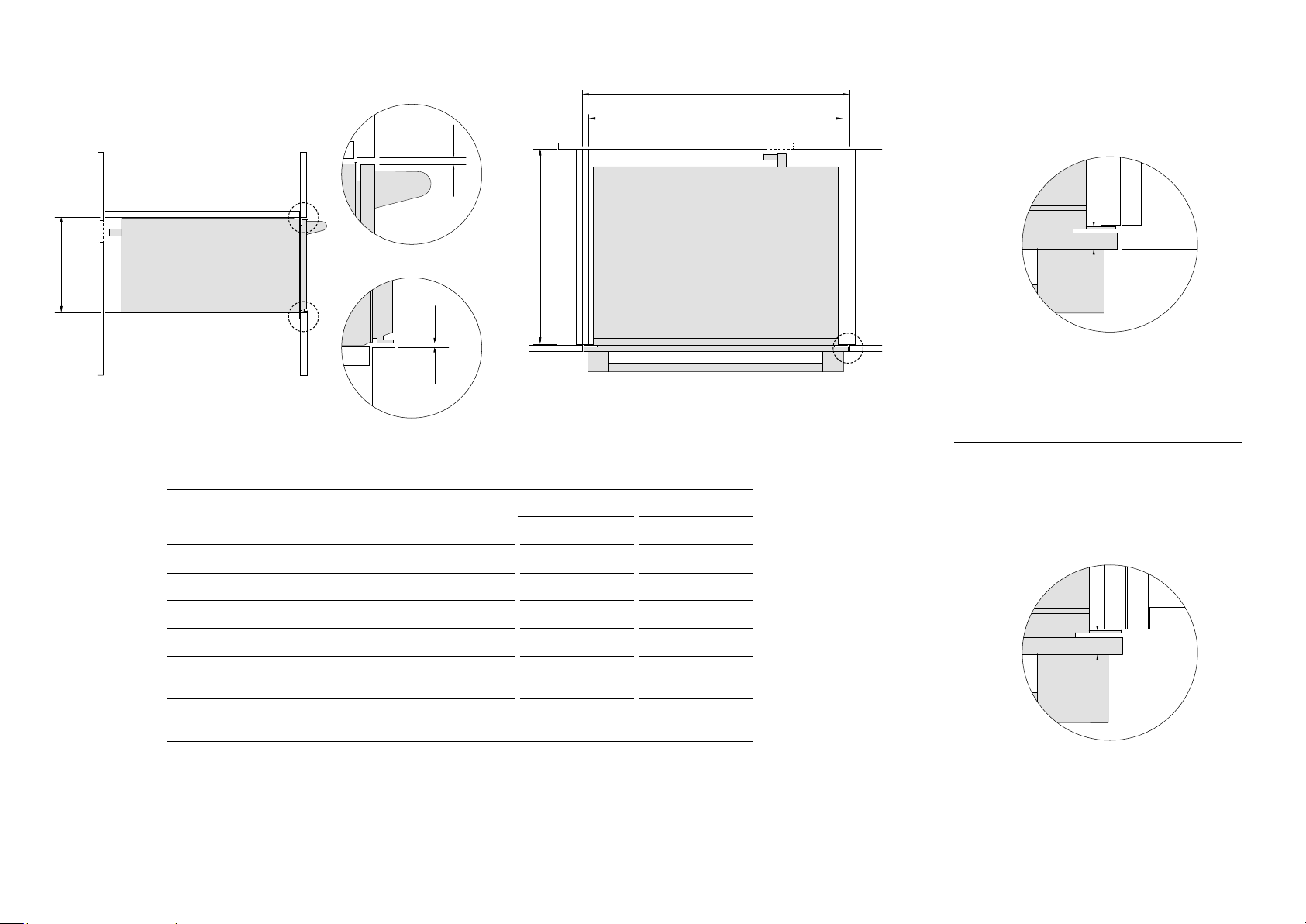
CABINETRY DIMENSIONS - 30” PROFESSIONAL MODELS
CABINETRY DIMENSIONS
WB30SP
INCHES MM
A Minimum inside height of cavity 10 3/4 273
B Minimum inside width of cavity 28 3/8 720
C Minimum inside depth of cavity 22 1/2 572
D Overall width of cabinetry 30 762
E Minimum clearance between top of front panel
and upper cabinetry panel
1/8 3
F Minimum clearance between bottom of front
panel and lower cabinetry panel
1/16 2
* The power outlet (PO) must be earthed and located within 35 7/16” (900mm) of the centre rear of the product.
FLUSH INSTALL
PROUD INSTALL
a
PROFILE
PO*
PLAN
c
b
d
PO*
f
e
Actual product dimension may vary by ± 1/16" (2 mm).
13/16 (20mm)*
13/16 (20mm)*
* Depth of drawer front panel including attachment flange.
14
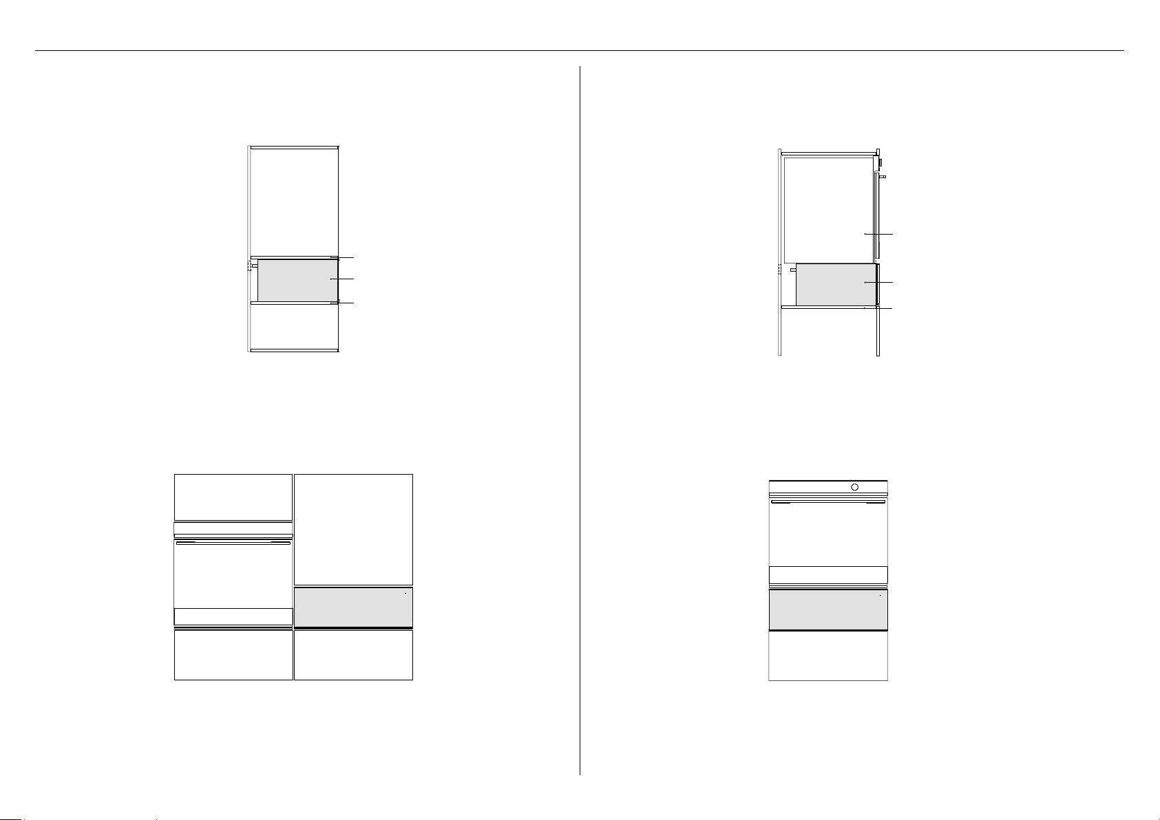
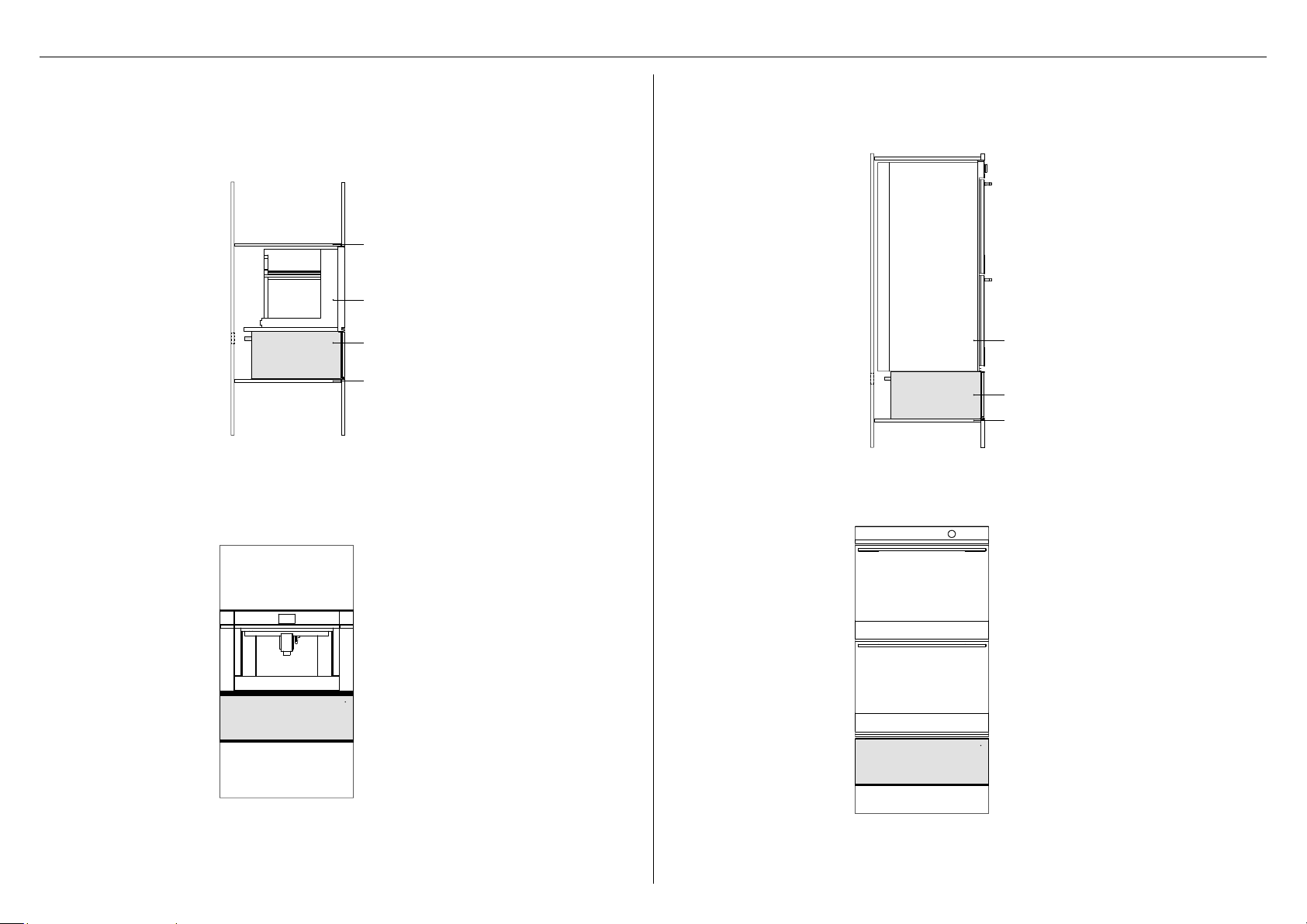
This installation is suitable for Minimal, Contemporary & Professional Warming drawers. A fixed
shelf must be provided above the warming drawer.
This combination is suitable for 24" and 30" Warming drawers that can fully support 24" and
30" Fisher & Paykel wall ovens, respectively.
PROFILE
Top shelf
Bottom shelf
Warming Drawer
FRONT
PROFILE
Single oven
Warming Drawer
FRONT
Bottom shelf
STANDALONE INSTALLATION COMBINED WITH SINGLE OVEN
INSTALLATION OPTIONS
15
This combination is suitable for 24" and 30" Warming drawers that can fully support 24" and
30" Fisher & Paykel companion products, respectively.
This combination is suitable for 30" Warming drawers that can fully support a
30" Fisher & Paykel double oven.
PROFILE
FRONT
Companion product
Warming Drawer
Top shelf
Bottom shelf
FRONT
PROFILE
Double oven
Warming Drawer
Bottom shelf
Actual product dimension may vary by ± 1/16" (2 mm).
COMBINED WITH COMPANION PRODUCT COMBINED WITH DOUBLE OVEN
INSTALLATION OPTIONS
16
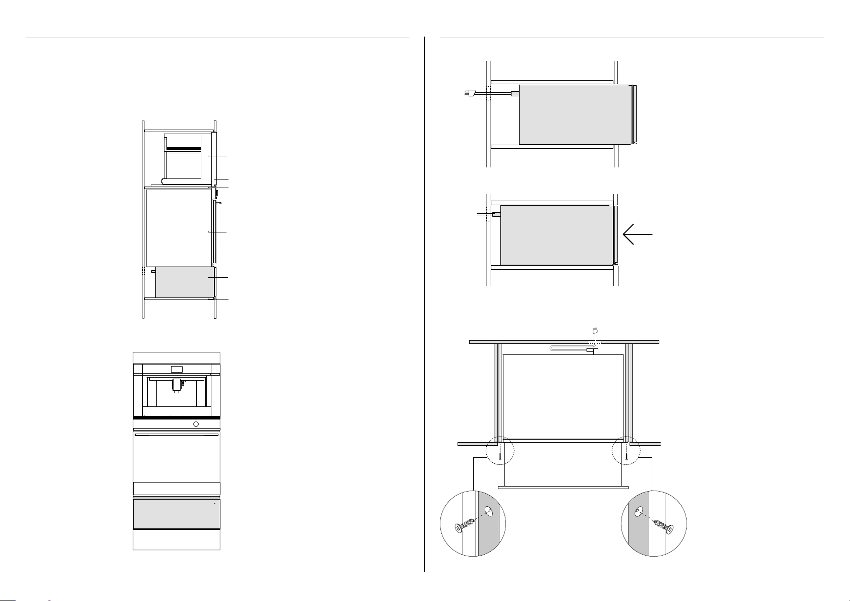
This combination is suitable for Minimal, Contemporary & Professional Warming drawers. The
30" model can fully support both 30" Fisher & Paykel single oven and companion product. A
shelf is required above the oven to support the companion product. Ensure the bottom shelf
can fully support the weight of all appliances.
INSTALLING THE DRAWER
FRONT
PROFILE
Companion product
Top shelf
Wall oven
Bottom shelf
Warming Drawer
30" Companion Trim Kit
Connect the power plug into the
power outlet.
Place the warming drawer carefully
inside the cabinetry.
1
Push the warming drawer back
into the cabinetry, and align the
front panel with the cabinetry as
desired.
2
3
Open the drawer and secure the
attachment flanges of the drawer
to the side edges of cabinetry with
4x25 T20 star head countersunk
screws.
PLAN VIEW
PROFILE
COMBINED WITH SINGLE OVEN & COMPANION PRODUCT
INSTALLATION OPTIONS
17
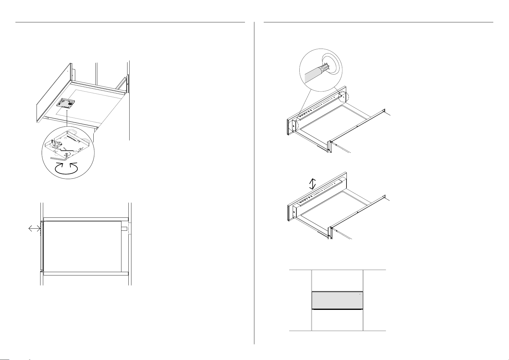
ADJUSTING THE DEPTH ADJUSTING THE HEIGHT
Open the drawer fully.
Using a hex key, turn the adjustment
screw to move the front panel forward.
Turn clockwise to move backwards or
counterclockwise to move forwards.
1
2
The depth is adjustable within
3/16" (4mm).
The depth of the front panel of the warming drawer can be adjusted to align with the
surrounding cabinetry.
Open the drawer fully, and slightly
loosen the screws.
1
2
3
Adjust to the required height and then
re-tighten the screws. The height is
adjustable within 1/16" (2mm).
Close the drawer and check the
alignment. Adjust again if necessary.
The front panel of the warming drawer can be adjusted vertically to align with the surrounding
cabinetry.
max 1/16" (2mm)

18
F the warming drawer is level and securely fitted to the cabinetry to
F any internal packaging has been removed from the drawer
F the isolating switch is accessible by the customer
F the bottom shelf can fully support the total weight of the combined appliances
F Open the drawer.
F Press the
1h
2h
1h
2h
1h
2h
1h
2h
FP WARMER DRAWER INTERFACE LOGIC_V1
PRODUCT OFF
THE THREE TEMPERATURE BUTTONS WORK AS A UNIT
ONLY ONE CAN BE SELECTED AND SHOW RED AT A TIME,
THE OTHER TWO BUTTONS SHOW WHITE
THE TWO TIMER BUTTONS WORK AS A UNIT
ONLY ONE CAN BE SELECTED AND SHOW RED AT A TIME,
THE OTHER BUTTON SHOWS WHITE
ICE AND WATER INTERFACE COMPONENTS
All bezels capable of glowing white and red
except fot the on /o bezel which only needs
to glow red.
Component Layout As Shown.
USER PRESSES ON/OFF BUTTON
ALL OTHER BEZELS GLOW WHITE EXCEPT
TEMPERATURE SETTING WHICH IS PRESET TO
MEDIUM AND GLOWS RED (PRODUCT STARTS
HEATING TO THE MEDIUM TEMPERATURE)
ON/OFF GLOWS RED UNTIL BUTTON IS PRESSED
AGAIN SHUTTING THE PRODUCT OFF.
WHEN THE TIMER BUTTON IS PRESSED THE
PRODUCT IS SET TO RUN FOR THE ALLOWED
TIME.
WHEN THIS TIME RUNS OUT THE PRODUCT SHUTS
OFF.
1h
2h
1h
2h
button to turn the warming drawer on.
F Shut the drawer.
F After 5-10 minutes, open the drawer to feel the internal surfaces of drawer is slightly
warmed.
F Press the
1h
2h
1h
2h
1h
2h
1h
2h
FP WARMER DRAWER INTERFACE LOGIC_V1
PRODUCT OFF
THE THREE TEMPERATURE BUTTONS WORK AS A UNIT
ONLY ONE CAN BE SELECTED AND SHOW RED AT A TIME,
THE OTHER TWO BUTTONS SHOW WHITE
THE TWO TIMER BUTTONS WORK AS A UNIT
ONLY ONE CAN BE SELECTED AND SHOW RED AT A TIME,
THE OTHER BUTTON SHOWS WHITE
ICE AND WATER INTERFACE COMPONENTS
All bezels capable of glowing white and red
except fot the on /o bezel which only needs
to glow red.
Component Layout As Shown.
USER PRESSES ON/OFF BUTTON
ALL OTHER BEZELS GLOW WHITE EXCEPT
TEMPERATURE SETTING WHICH IS PRESET TO
MEDIUM AND GLOWS RED (PRODUCT STARTS
HEATING TO THE MEDIUM TEMPERATURE)
ON/OFF GLOWS RED UNTIL BUTTON IS PRESSED
AGAIN SHUTTING THE PRODUCT OFF.
WHEN THE TIMER BUTTON IS PRESSED THE
PRODUCT IS SET TO RUN FOR THE ALLOWED
TIME.
WHEN THIS TIME RUNS OUT THE PRODUCT SHUTS
OFF.
1h
2h
1h
2h
button to turn the warming drawer off and shut the drawer.
Complete and keep for safe reference:
Model
Serial No.
Purchase Date
Purchaser
Dealer Address
Installer’s Name
Installer’s Signature
Installation Company
Installation Date
INSTALLER CHECKLIST
IMPORTANT!
Read all installation instructions in this manual to see if the unit has been correctly installed.
Ensure that installation has been completed correctly before use.
Ensure that: Test operation:


592133A 07.20
FISHERPAYKEL.COM
© Fisher & Paykel Appliances 2020. All rights reserved.
The models shown in this guide may not be available in all markets
and are subject to change at any time.
The product specifications in this guide apply to the specific products and
models described at the date of issue. Under our policy of continuous product
improvement, these specifications may change at any time.
For current details about model and specification availability in your country,
please go to our website or contact your local Fisher & Paykel dealer.